Download ELECRAFT KPA3 Specifications

Transcript
ELECRAFT K3
HIGH-PERFORMANCE 160 – 6 METER
TRANSCEIVER
KPA3 100-WATT AMPLIFIER OPTION
INSTALLATION INSTRUCTIONS
Rev G, July 25, 2011
Copyright © 2011, Elecraft, Inc.
All Rights Reserved
Contents
Introduction............................................................................................................................................... 3 Customer Service and Support ............................................................................................................................ 3 Technical Assistance ....................................................................................................................................... 3 Repair / Alignment Service ............................................................................................................................. 3 Preventing Electrostatic Discharge Damage ............................................................................................ 4 How ESD Damage Occurs .................................................................................................................................. 4 Preventing ESD Damage..................................................................................................................................... 4 Preparing for Installation .......................................................................................................................... 5 Tools Required .................................................................................................................................................... 5 Parts Included ...................................................................................................................................................... 6 Installation Procedure ............................................................................................................................... 7 Removing the KRX3 Subreceiver Module ......................................................................................................... 9 Removing the KNB3 Module ........................................................................................................................... 10 Installing the KPA3 Shield................................................................................................................................ 11 Installing the KPAIO3 Interface Module .......................................................................................................... 12 Assembling the Fan Panel ................................................................................................................................. 14 Installing the KPA3 Amplifier Module ............................................................................................................. 16 Installing the Fan Panel ..................................................................................................................................... 16 Replacing the KNB3 Module ............................................................................................................................ 18 Replacing the KRX3 Module ............................................................................................................................ 18 Replacing the Covers ........................................................................................................................................ 19 Configuring and Calibrating the KPA3 ............................................................................................................. 20 Circuit Description.................................................................................................................................. 21 KPAIO3 ............................................................................................................................................................ 21 KPA3 Fan Panel ................................................................................................................................................ 21 KPA3 Power Amplifier ..................................................................................................................................... 21 2
Introduction
This manual covers the installation of the KPA3 100-watt amplifier option in your K3 transceiver. Only a few
basic hand tools are needed (see page 5) to perform the installation. No soldering or wiring is required.
The KPA3 option consists of three subassemblies: the KPA3 power amplifier, a fan panel, and the KPAIO3
interface module. More details about the KPA3 are provided under Circuit Description on page 21.
Customer Service and Support
Technical Assistance
You can send e-mail to [email protected] and we will respond quickly - typically the same day Monday
through Friday. Telephone assistance is available from 9 A.M. to 5 P.M. Pacific time (weekdays only) at
831-763-4211. Please use e-mail rather than calling when possible since this gives us a written record of the
details of your problem and allows us to handle a larger number of requests each day.
Repair / Alignment Service (We want to make sure everyone succeeds!)
If necessary, you may return your Elecraft product to us for repair or alignment. (Note: We offer unlimited email
and phone support to get your kit running, so please try that route first as we can usually help you find the
problem quickly.)
IMPORTANT: You must contact Elecraft before mailing your product to obtain authorization for the
return, what address to ship it to and current information on repair fees and turn around times. (Frequently we
can determine the cause of your problem and save you the trouble of shipping it back to us.) Our repair location
is different from our factory location in Aptos. We will give you the address to ship your kit to at the time of
repair authorization. Packages shipped to Aptos without authorization will incur an additional shipping charge
for reshipment from Aptos to our repair depot.
Elecraft's 1-Year Limited Warranty
This warranty is effective as of the date of first consumer purchase (or if shipped from factory, date product is shipped
to customer). It covers both our kits and fully assembled products. For kits, before requesting warranty service, you
should fully complete the assembly, carefully following all instructions in the manual.
Who is covered: This warranty covers the original owner of the Elecraft product as disclosed to Elecraft at the time of
order. Elecraft products transferred by the purchaser to a third party, either by sale, gift or other method, who is not
disclosed to Elecraft at the time of original order, are not covered by this warranty. If the Elecraft product is being
bought indirectly for a third party, the third party's name and address must be provided to Elecraft at time of order to
insure warranty coverage.
What is covered: During the first year after date of purchase, Elecraft will replace defective or missing parts free of
charge (post-paid). We will also correct any malfunction to kits or assembled units caused by defective parts and
materials. Purchaser pays inbound shipping to Elecraft for warranty repair, Elecraft will pay shipping to return the
repaired equipment to you by UPS ground service or equivalent to the continental USA and Canada. Alaska, Hawaii
and outside U.S. and Canada actual return shipping cost paid by owner.
What is not covered: This warranty does not cover correction of kit assembly errors. It also does not cover
misalignment; repair of damage caused by misuse, negligence, or builder modifications; or any performance
malfunctions involving non-Elecraft accessory equipment. The use of acid-core solder, water-soluble flux solder, or any
corrosive or conductive flux or solvent will void this warranty in its entirety. Also not covered is reimbursement for loss
of use, inconvenience, customer assembly or alignment time, or cost of unauthorized service.
Limitation of incidental or consequential damages: This warranty does not extend to non-Elecraft equipment or
components used in conjunction with our products. Any such repair or replacement is the responsibility of the customer.
Elecraft will not be liable for any special, indirect, incidental or consequential damages, including but not limited to any
loss of business or profits.
3
Preventing Electrostatic Discharge Damage
There is no climate or work location where the components of your K3 are safe from Electrostatic Discharge
(ESD) unless you take specific steps to prevent such damage. Many of the components in your K3 can be
damaged by static discharges of only a few volts: far too little for you to notice. Those low-voltage but
destructive discharges easily happen anywhere and in almost any environment.
ESD damage may not be apparent at first. The damaged components may not fail completely. Instead, the
damage may result in below-normal performance for an extended period of time before you experience a total
failure.
How ESD Damage Occurs
Whenever an object containing a static charge touches a circuit in your K3, current will rush into the circuit until
the components reach the same voltage as the source of the static charge. If the voltage or current that passes
through a component during that brief period exceeds its normal operating specifications, it may be damaged or
destroyed.
Preventing ESD Damage
ESD damage cannot occur if there is no voltage difference between the components in your K3 and any object
that touches them. That is how anti-static packaging works. Anti-static bags allow the static charge to flow over
their surface, so that any part of the bag that touches the components inside are all at the same potential at all
times. Anti-static foam keeps the leads of sensitive components at the same potential.
At your work bench, avoiding a dangerous voltage is achieved most easily by tying everything together and
connecting them to a common mains safety ground. This includes your K3, individual boards or other sensitive
components as well as everything they may touch at the work table.
Inexpensive static dissipating work mats are readily-available that will steadily and safely drain off any charges
built up on parts or circuit boards placed on them. They are supplied with a lead that connects the mat to the
common workbench ground. Also, metal cabinets on test equipment used on the bench should be tied together
and connected to the common ground.
Most importantly, you must have a way of continuously draining off any static charges that occur on your body.
Such charges are easy to create, even while sitting quietly at the work bench. Moving your feet on the floor,
shifting position in your chair or even moving your arms so that clothing rubs against itself can produce
destructive static charges. You can discharge yourself by touching an unpainted metal ground, but that will last
only until you move in a way that produces a new static charge. The safest technique is to wear a grounded wrist
strap with a series 1-megohm resistor that continuously drains off any charges. Such wrist straps are readilyavailable and inexpensive.
WARNING
DO NOT attach a ground directly to yourself without a current-limiting resistor as this poses
a serious shock hazard. A wrist strap must include a 1-megohm resistor to limit the current
flow. If you choose to touch an unpainted, metal ground to discharge yourself, do it only
when you are not touching any live circuits with your other hand or any part of your body.
4
We strongly recommend you take the following anti-static precautions (listed in order of importance) to avoid
trouble:

Leave ESD-sensitive parts in their anti-static packaging until you install them. The packaging may be a
special plastic bag or the component’s leads may be inserted in conductive foam. Parts which are
especially ESD-sensitive are identified in the parts list and in the assembly procedures.

Wear a conductive wrist strap with a series 1-megohm resistor. If you do not have a wrist strap, touch a
ground briefly before touching any sensitive parts to discharge your body. Do this frequently while you
are working. You can collect a destructive static charge on your body just sitting at the work bench. DO
NOT attach a ground directly to yourself as this poses a serious shock hazard.

Use a grounded anti-static mat on your work bench.

If you choose to use a soldering iron to work on your K3 for any reason, be sure your iron has an ESDsafe grounded tip tied to the same common ground used by your mat or wrist strap.
Preparing for Installation
Tools Required
1.
#0 and #1 size Phillips screwdrivers. To avoid damaging screws and nuts, a power screwdriver is not
recommended. Use the screwdriver that best fits the screw in each step.
2. Small diagonal cutters.
3. Needle-nose pliers.
4. Soft cloth or clean, soft static dissipating pad to lay cabinet panels on to avoid scratching.
The following tools are strongly recommended:
1. ESD wrist strap.
2. Static dissipating work pad.
5
Parts Included
The following parts should be included in your kit. Check to ensure you have them all. If any parts are damaged
or missing, contact Elecraft for replacements (see Customer Service and Support, page 3).
CAUTION
In addition to taking ESD precautions, be careful not to damage components on either side of the
circuit boards when handling them. This is especially true of the KPA3 module because of the
weight of the heat sink.
QTY.
ELECRAFT
PART NO.
1
E850273
1
E850271
Fan Panel
1
E100288
Fan with short lead
1
E850293
Fan with long lead
1
E850294
Finger Guard
2
E980143
Circuit Breaker, 20A
1
E980128
ILLUSTRATION
DESCRIPTION
KPA3 Module
ESD Sensitive.
KPAIO3 Interface Module
ESD Sensitive
6
QTY.
ELECRAFT
PART NO.
Rear Shield
1
E100217
Screw, 4-40, 1/4” (6.4 mm) Zinc, Pan
Head
9
E700005
Screw, 4-40, 1/4” (6.4 mm) Black, Pan
Head
1
E700009
Screw, 4-40, 3/8” (9.5 mm) Black, Flat
Head
1
E700131
Screw, 4-40, 7/8” (22 mm ) Black, Flat
Head
8
E700159
Acorn Nut, 4-40
8
E700160
Standoff, 4-40, 5/16” (7.9 mm) long
1
E700121
Lock Washer, #4 Inside Tooth
4
E700010
Lock Washer, #4 Split
4
E700004
Nut, 4-40
1
E700011
ILLUSTRATION
DESCRIPTION
Installation Procedure
K3 KIT BUILDERS: If you were directed here to install the KPA3 module as part of the initial
K3 assembly, begin here to complete the installation. Skip over the steps indicated.
Disconnect power and all cables from your K3.
7
Remove the nine screws to free the top cover as shown in Figure 1. After the cover is open, lift it gently to
reach the speaker wire connector. Unplug the speaker and set the top cover aside in a safe place.
Figure 1. Removing K3 Top Cover.
CAUTION: Touch an unpainted metal ground or wear a grounded wrist strap
before touching components or circuit boards inside the K3. See Preventing ESD Damage on
page 4 for more information.
On the rear of the K3, remove the large blank panel above the GND screw. This panel will not be used
again, but the screws will be needed to mount the KPA3 cooling fans. (If you are installing the KPA3 as part of
building your K3 kit, this panel may not be installed.). Newer panels have a hole marked ANT3 for the antenna
connection to the optional K144XV 2-meter module. If you do not have the K144XV option, a plastic plug will
fill this hole. Remove the plug or the antenna connector. To prevent accidental short circuits, either tape the
metal end of the BNC connector or unplug the cable from the K144XV module and remove it entirely for now.
Turn the K3 upside down and remove the bottom cover(s) as shown in Figure 2. Note that, if you are
finishing the KPA3 installation after assembling your K3 kit, only the rear portion of the bottom cover need be
removed.
Figure 2. Removing the K3 Bottom Covers.
8
K3 KIT BUILDERS: If you are installing the KPA3 as part of the initial K3 kit assembly, skip
the following steps and resume with Installing the KPAIO3 Interface Module on page 12
Remove the stiffener bar that runs from side to side across the top of the K3 chassis. This is the bar the
center three screws in the top cover thread into. The bar is held in place by a single screw at each side.
Removing the KRX3 Subreceiver Module
If your K3 is equipped with the optional KRX3 Subreceiver, you must remove the subreceiver module to install
the KPA3 shield. The KRX3 subreceiver module is the “L” shaped metal enclosure shown in Figure 3. The K3
in the figure has a fully-installed KPA3 showing how it fits next to the KRX3 module.
Remove the subreceiver module as follows:
Remove the chassis stiffener bar that runs across the top of the K3 chassis and is attached to the side panels.
Remove the two 1-1/2” (38 mm) screws and lock washers shown in Figure 3. These screws extend all the
way through the KRX3 module and secure it to standoffs mounted on the main RF board that fills the bottom of
the K3.
Figure 3. Removing the KRX3 Module.
In the following steps you will handle small TMP coaxial connectors. These are frictionfit connectors shown in Figure 4. Handle the connectors by the grips as shown. Do not pull
on the coaxial cable.
Figure 4. TMP Coaxial Connectors.
9
Hold the KRX3 module by the two brass knurled nuts on the top, and lift it straight up to gain access to the
small TMP coaxial connectors plugged into the module. There are two along the front. There may be one at the
back as well, depending upon the options installed. As you lift the KRX3 module, it will unplug from two small
interface circuit boards. One is at the front and the other is at the rear. These small boards may come out with
the module or they may remain attached to the K3 main RF board.
Unplug the TMP coaxial cables leading to the KRX3 module, then lift the module free and set it aside.
Locate the two small interface circuit boards that fit between the connectors on the KRX3 module and the
connectors on the K3 RF board. Remove them and put them in a safe place.
Unplug and remove the loose TMP cables that were connected to the KRX3 module. If your K3 is equipped
with a cable connected to a BNC connector at the rear panel AUX RF input, this cable will not unplug. It is
permanently attached to the BNC connector Wrap the metal TMP connector in insulating tape to ensure it
cannot short to any circuits inside the K3.
CAUTION: You will apply power to make tests before reinstalling the KRX3 module
again. If the loose cables are not removed or insulated to prevent shorts as described in the
previous step, you may destroy circuits in your K3 when you apply power.
Removing the KNB3 Module
KNB3 module must be removed to provide clearance needed to install the KPA3 shield in the following section.
Remove the KNB3 module, the standoff, screw and washers from the RF board (see Figure 5). They will be
reinstalled later.
CAUTION: The KNB3 module is ESD sensitive. Put it in a safe place until you
reinstall it.
Figure 5. Removing the KNB3 Module.
10
Installing the KPA3 Shield
Remove the three screws, washers and standoffs (on the bottom of the RF) board shown in Figure 6. Save
the lock washers and standoffs. The screws will not be reused.
Figure 6. Rear Shield Mounting Screw Locations.
Set the rear shield in place as shown in Figure 7.
Figure 7. Positioning the Rear Shield.
Loosely secure the rear shield with three 1/4” (6.4 mm) zinc pan head screws, the lock washers and
standoffs you removed earlier as shown in Figure 8.
11
Place a black 4-40 3/8” (9.5 mm) flat head screw through the hole in the back panel and the tab at the top
edge of the shield as shown in Figure 8. Secure it with a #4 inside tooth lock washer and 4-40 nut.
Figure 8. Rear Shield Installed.
Tighten the three screws holding the bottom of the shield and the screw at the top on the back panel. Do not
over-tighten but be sure all four screws are tight. Don’t overlook one! Good contact is essential for the shield
to perform correctly.
Installing the KPAIO3 Interface Module
K3 KIT BUILDERS: Resume the installation with the following step.
Locate PA Jumper block mounted on RF board connectors P67A and P67B just inside the opening for the
fans. Unplug the Jumper Block. Put the Jumper Block in a safe place. You’ll need it if you want to operate the
K3 without the KPA3 module installed.
Figure 9. Removing PA Jumper Block.
12
On the KPAI03 board, install a 5/16” (7.9 mm) 4-40 standoff near K1 as shown in Figure 10. Use the exact
hardware shown. This is important so that the height of the standoff is correct when it is mounted in the K3.
Figure 10. Installing Standoff on the KPAIO3 Board.
As you install components and reassemble your K3, be sure all the screws are in place
and secure, but do not over tighten them. Failure to tighten all screws may result in poor
shielding of sensitive components, resulting in possible noise or birdies in the receiver as well
as other difficult-to-trace problems.
If you are adding the KPA3 after assembling your K3 from a kit, remove the rear section of the bottom
cover (see Figure 2 on page 8) in order to properly support the RF board in the following step.
Install the KPAIO3 board just inside the opening in the rear panel as shown in Figure 11. Connector J67A
on the KPAIO3 mates with P67A on the RF board, and J67B on the KPAIO3 mates with P67B on the RF board.
These connectors may fit very tightly. Press one side then the other as needed to fully mate the connectors
while supporting the RF board from below with your fingers. When the connectors are fully mated, the
standoff on the KPAIO3 will line up with the hole in the back panel. Secure the KPAIO3 with a 4-40 1/4” (6.4
mm) black pan head screw. Do not use a washer.
Figure 11. Installing the KPAIO3 Module.
13
Assembling the Fan Panel
Locate the fan panel and mount the fans as shown in Figures 12 and 13 using 4-40 7/8” black flat head
screws and acorn nuts. Note that the appearance of the fans in your kit may differ slightly from those shown.
If you purchased the optional Stainless Steel screw kit, use the 4-40, 7/8” black flat had
screws and acorn nuts from the kit to mount the fans on the panel as described below.
Include a stainless steel interior tooth lock washer from the kit under each acorn nut.
1. Orient the fans with the side with the manufacturer’s label facing away from the panel.
2. The fans have leads with different lengths. Position them on the panel as shown.
3. As you tighten the acorn nuts, adjust the position of each finger guard so it is straight and aligned with
the fan opening.
Figure 12. Fan Panel Inside View.
Figure 13, Completed Fan Panel from Rear.
14
Install the 20A circuit breaker in the small hole with the pushbutton on the same side as the fans as shown
in Figure 13.
Position the fan panel near the rear opening and plug the fan leads into the connectors in the upper right
corner of the KPAIO3 board as shown in Figure 14. Be sure to orient the connectors so the red lead is to the left
as indicated on the board. If the connectors don’t want to slide onto the pins, check to see if there is any extra
plastic on the side facing the board. If so, trim it smooth with a hobby knife or your diagonal cutters.
Figure 14. Connecting Fans to the KPAIO3 Board.
CAUTION: If you removed a KRX3 subreceiver module, be sure the loose TMP
cables have been removed or the metal TMP connectors are fully insulated with electrical
tape before proceeding. Otherwise accidental shorts may destroy circuits in your K3.
Connect a power supply to your K3 and test the fans and KPAIO3 interface control as follows:
Press the POWER button to turn the K3 on.
Hold C O N F I G to select the Configuration menu, then turn VFO B to KPA3. Normally, the display will
indicate NOT INST (not installed).
Turn the VFO A knob to PAIO ON, then turn it further to PAIO TST. When moving between ON and
TST, you should hear a relay click on the KPAIO3 board. If you don’t, press the K3 POWER button to
switch it off, then on again and retry the test.
Turn the VFO A knob on past TST to FN1, then FN2, FN3 and FN4. The fans should start turning at
FN1 and increase speed as you continue to FN4.
Turn the K3 off and disconnect the power supply.
Unplug the fans and set them aside for now.
15
Installing the KPA3 Amplifier Module
Your KPA3 module may produce a rattling sound when shaken. This is normal. It is
caused by ferrite beads sliding along wire leads in the module.
Place the KPA3 module inside the shield from the top. Mate the two connectors fully with the KPAIO3
board as shown in Figure 15. Like the KPAIO3 to RF board connectors, these connectors may require some
force to mate them fully. Do not place undue pressure on the RF board without supporting it. Recommend you
place your fingers on the bottom of the RF board, under the connectors to the KPAIO3 board, and squeeze down
with your thumbs on the KPA3 board above the connectors until they are fully mated.
Figure 15. Mounting the KPA3 Module.
Secure the KPA3 module to the rear shield tabs with three 4-40, 1/4” (6.4mm) zinc pan head screws. Place
a #4 inside tooth lock washer under each screw head.
Installing the Fan Panel
Current KPA3 fan panels have a hole near the circuit breaker marked ANT3 for the antenna connection to
the optional K144XV 2-meter module:

If you are adding the KPA3 to a K3 that has the K144XV option installed, install the connector and
cable you removed from the blank panel earlier in the ANT3 hole in the fan panel. Route the antenna
cable along the top of the KPA3 pc board across the opening for the fans and through the opening in the
shield near the KIO3 board.

If you do not have the K144XV option, a plastic plug is provided to fill this hole. Use the plug you
removed from the hole marked ANT3 in t he existing blank panel if you are updating a built K3. If you
are installing the KPA3 while building your K3 kit, the plug will be in the K3 Miscellaneous Bag.
16
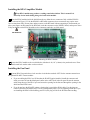
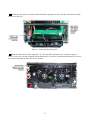
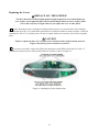
Position the fan panel you assembled earlier behind the opening at the rear of the K3 and connect the leads
as shown in Figure 16.
Figure 16. Connecting Fan Panel to K3.
Mount the fan panel on the K3 using four 3/16” (4.8 mm) black pan head screws as shown in Figure 17.
These are the screws you that originally held the blank panel. If you haven’t installed the blank panel, the screws
are included with basic K3 parts. Do not use washers.
Figure 17. Fan Panel Installed on K3.
17
Dress the fan leads so they are well clear of the fan blades. Check to ensure both fans turn freely.
Figure 18. Positioning the Fan Leads.
K3 KIT BUILDERS: Skip the following steps. Resume with Replacing the Covers on page 19
Replacing the KNB3 Module
Replace the standoff and the KNB3 module you removed earlier (see Figure 5). When mounting the
standoff on the RF board, be sure to place one lock washer under the screw head on the bottom of the board, and
two lock washers between the standoff and the top of the board. A fourth lock washer goes under the screw
holding the KNB3 module itself.
Replacing the KRX3 Module
If your K3 is not equipped with the KRX3 Subreceiver, go directly to Replacing the Covers below to continue.
If your KRX3 installation uses the Auxiliary Antenna input to the KRX3, a coaxial cable will be present
that runs from the KAT3 or from a connector on the rear panel AUX RF connector. Refer to your KRX3
Subreceiver Installation and Operation manual, Auxiliary KRX3 Antenna Input (Optional) section for
instructions on how to route this cable across the KPA3 enclosure to reach the KRX3 module.
Turn to your KRX3 Subreceiver Installation and Operation manual, Installing the KRX3 Subreceiver
Module section to replace the KRX3 module. Be especially careful to do the following as described in that
procedure:
Be sure the cover on battery BT1 on the K3 RF board is in place. The cover is essential to avoid
shorting the battery. The outer rim of the battery is the positive terminal, and may come in contact with
the grounded bottom of the KRX3 enclosure if the cover is not in place.
Be sure all the TMP cables are properly connected or your K3 will not operate properly.
Be sure the TMP cable to J85 on the subreceiver module is routed as shown to prevent signal leakage
between the KRX3 and the K3 main receiver.
18
Replacing the Covers
REPLACE ALL THE SCREWS!
The K3's chassis has excellent rigidity despite its light weight. The screws that hold the top
cover in place are an important part of the structural design. Please be sure to replace all the
screws and verify they are tight whenever you replace the cover or other panels
Replace the bottom cover(s) using the 4-40 black pan head screws you removed earlier. Note that three
locations take the 4-40 1/4” (6.4 mm) black pan head screws with lock washers as shown in Figure 2 while the
remainder are 4-40 3/16” (4.8 mm) screws. Be sure to replace all the screws securely, but do not over tighten
them!
CAUTION!
Failure to replace the three 1/4” (6.4 mm) screws and lock washers in the locations shown in
Figure 2 may destroy power transistors in your K3!
If you removed it earlier, replace the stiffener bar and attach it to the KPA3 shield with two 4-40, 1/4”
(6.4mm) zinc pan head screws with #4 inside tooth lock washers as shown in Figure 19.
Figure 19. Installing the Chassis Stiffener Bar.
19
Hold the top cover above the K3, route the speaker wire under the stiffener bar and plug it into P25 on the
KIO3 board at the left rear of the K3 as shown in Figure 20.
Figure 20. Connecting Speaker Cable.
Position the top cover on the K3. Note that the tab on the back center goes under the rear lip of the K3 rear
panel. Secure the top cover with the nine 4-40 3/16” (4.8 mm) black flat head screws you removed earlier.
Configuring and Calibrating the KPA3
Your KPA3 will not operate correctly until the following steps are completed!
Reconnect power and a dummy load capable of dissipating 50 watts to your K3.
Refer to your Owner’s manual, turn on your K3 and do the following:
Enable the KPA3 as described under Configuration, Option Module Enables.
Perform the PA Temperature Sensor Calibration as described under Calibration Procedures
immediately, while the K3’s internal temperature is as close to ambient room temperature as possible.
Perform the Transmitter Gain Calibration as follows. This is essential for your KPA3 to operate
properly.
If you do not have a computer, perform the manual High Power (50W) TX Gain Calibration procedure in the
Calibration Procedures, Transmitter Gain section of your Owner’s manual.
If you have a Windows, Linux or Macintosh computer with an RS232 interface and cable, and an internet
connection, perform the automated TX Gain calibration using the K3 Utility program as follows:
Ensure you have the Elecraft K3 Utility Ver. 1.1.12.28 or later on your computer. The utility is available
for downloading from the Elecraft web site: www.elecraft.com
Connect your computer to your K3’s RS232 port and start the K3 Utility program.
Click on the K3 Utility “Configuration” tab, “Calibrate Transmitter Gain…” and follow the instructions
to perform the 5-Watt and 50-Watt Transmitter Gain Calibration procedures.
That completes the installation of the KPA3 power amplifier in your K3 transceiver.
20
Circuit Description
The KPA3 option consists of three subassemblies: the KPA3 power amplifier, a fan panel to provide cooling,
and the KPAIO3 interface module.
KPAIO3
The KPAIO3 acts as an interface between the RF board and the KPA3 power amplifier. It includes a relay that
allows the KPA3 to be bypassed when it is not needed during low power operation. The cooling fans are also
controlled by circuitry on the KPAIO3. There are four fan speeds, plus OFF, selected automatically based on
measurement of the KPA3 heat sink temperature.
KPA3 Fan Panel
The KPA3 Fan Panel replaces the blank panel equipped with the K3/10. Two fans are mounted on this panel,
along with a circuit breaker to protect the KPA3 from accidental short circuits. The fan panel is connected to the
KPAIO3 fan connectors and to the heavy 12-volt connections of the KPA3 module.
KPA3 Power Amplifier
The KPA3 Power Amplifier consists of two RF power transistors operating as a broadband push-pull amplifier;
a PIN diode TR switch; and associated bias and control circuitry. The KPA3 provides the necessary gain to
increase the power output of the K3 from 10 watts to 100 watts from 1.8 MHz and 54 MHz. A heat sink is
provided that, together with the cooling fans, provides the necessary cooling to maintain the operating
temperature of the output transistors at a safe level.
The KPA3 is mounted in the K3 with the circuit side of the board down so that only the heat sink is visible after
removing the top cover. Each KPA3 is fully tested at the factory and there are no end user adjustments needed
during installation.
21