1
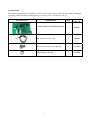
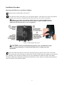
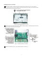
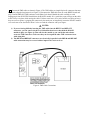
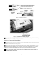
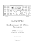
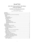
ELECRAFT K3 HIGH-PERFORMANCE 160 – 6 METER TRANSCEIVER K144XV REFERENCE OSCILLATOR PHASE LOCK OPTION INSTALLATION Revision A1, April 13, 2011 Copyright © 2011, Elecraft, Inc. All Rights Reserved Contents Introduction............................................................................................................................................. 3 Customer Service and Support ............................................................................................................................ 3 Installing the K144XV Phase Lock Board............................................................................................ 4 Anti Static Protection Required........................................................................................................................... 4 Preparing for Installation..................................................................................................................................... 4 Tools Required ................................................................................................................................................ 4 Firmware Required.......................................................................................................................................... 4 Parts Included .................................................................................................................................................. 5 Installation Procedure.......................................................................................................................................... 6 Removing the K3Top Cover and Chassis Stiffener ........................................................................................ 6 Installing the Phase Lock Board...................................................................................................................... 7 Installing the Firmware and Testing the Board ............................................................................................... 9 Replacing the Top Cover .............................................................................................................................. 10 Recalibrating the XV144 ...................................................................................................................... 11 2 Introduction This option phase locks the local oscillators in the K144XV to the KREF3 master reference oscillator in the K3. The circuitry is contained on the K144XV Phase Lock Board that mounts onto the K144XV pc board inside the K144XV 2-Meter module enclosure. No soldering is required to install this option. Customer Service and Support Technical Assistance You can send e-mail to [email protected] and we will respond quickly - typically the same day Monday through Friday. Telephone assistance is available from 9 A.M. to 5 P.M. Pacific time (weekdays only) at 831-763-4211. Please use e-mail rather than calling when possible since this gives us a written record of the details of your problem and allows us to handle a larger number of requests each day. Repair / Alignment Service (We want to make sure everyone succeeds!) If necessary, you may return your Elecraft product to us for repair or alignment. (Note: We offer unlimited email and phone support to get your kit running, so please try that route first as we can usually help you find the problem quickly.) IMPORTANT: You must contact Elecraft before mailing your product to obtain authorization for the return, what address to ship it to and current information on repair fees and turnaround times. (Frequently we can determine the cause of your problem and save you the trouble of shipping it back to us.) Our repair location is different from our factory location in Aptos. We will give you the address to ship your kit to at the time of repair authorization. Packages shipped to Aptos without authorization will incur an additional shipping charge for reshipment from Aptos to our repair depot. Elecraft's 1-Year Limited Warranty This warranty is effective as of the date of first consumer purchase (or if shipped from factory, date product is shipped to customer). It covers both our kits and fully assembled products. For kits, before requesting warranty service, you should fully complete the assembly, carefully following all instructions in the manual. Who is covered: This warranty covers the original owner of the Elecraft product as disclosed to Elecraft at the time of order. Elecraft products transferred by the purchaser to a third party, either by sale, gift or other method, who is not disclosed to Elecraft at the time of original order, are not covered by this warranty. If the Elecraft product is being bought indirectly for a third party, the third party's name and address must be provided to Elecraft at time of order to insure warranty coverage. What is covered: During the first year after date of purchase, Elecraft will replace defective or missing parts free of charge (post-paid). We will also correct any malfunction to kits or assembled units caused by defective parts and materials. Purchaser pays inbound shipping to Elecraft for warranty repair, Elecraft will pay shipping to return the repaired equipment to you by UPS ground service or equivalent to the continental USA and Canada. Alaska, Hawaii and outside U.S. and Canada actual return shipping cost paid by owner. What is not covered: This warranty does not cover correction of kit assembly errors. It also does not cover misalignment; repair of damage caused by misuse, negligence, or builder modifications; or any performance malfunctions involving non-Elecraft accessory equipment. The use of acid-core solder, water-soluble flux solder, or any corrosive or conductive flux or solvent will void this warranty in its entirety. Also not covered is reimbursement for loss of use, inconvenience, customer assembly or alignment time, or cost of unauthorized service. Limitation of incidental or consequential damages: This warranty does not extend to non-Elecraft equipment or components used in conjunction with our products. Any such repair or replacement is the responsibility of the customer. Elecraft will not be liable for any special, indirect, incidental or consequential damages, including but not limited to any loss of business or profits. 3 Installing the K144XV Phase Lock Board Anti Static Protection Required We strongly recommend you take the following anti-static precautions (listed in order of importance) to avoid ESD (Electro Static Discharge) damage: Leave ESD-sensitive parts in their anti-static packaging until you install them. The packaging may be a special plastic bag or the component’s leads may be inserted in conductive foam. Parts which are especially ESD-sensitive are identified in the parts list and in the assembly procedures. Wear a conductive wrist strap with a series 1-megohm resistor. If you do not have a wrist strap, touch a bare metal ground briefly before touching any sensitive parts to discharge your body. Do this frequently while you are working. You can collect a destructive static charge on your body just sitting at the work bench. WARNING DO NOT attach a ground directly to yourself without a current-limiting resistor as this poses a serious shock hazard. A wrist strap must include a 1megohm resistor to limit the current flow. If you choose to touch an unpainted, metal ground to discharge yourself, do it only when you are not touching any live circuits with your other hand or any part of your body. Use a grounded anti-static mat on your work bench. No soldering is required but if you choose to use a soldering iron for any reason, be sure your iron has an ESD-safe grounded tip tied to the same common ground used by your mat or wrist strap. Preparing for Installation Tools Required 1. #0 and #1 size Phillips screwdrivers. To avoid damaging screws and nuts, a power screwdriver is not recommended. Use the screwdriver that best fits the screw in each step. 2. Soft cloth or clean, soft static dissipating pad to lay cabinet panels on to avoid scratching. The following tools are strongly recommended: 1. ESD wrist strap. 2. Static dissipating work pad. 3. Long (needle) nose pliers or sturdy tweezers (for handling small cables in tight spaces) Firmware Required You must have Firmware version 1.03 or later available for loading into the K144XV, the special RS232 cable used with the K144XV for updating firmware, and your computer available. The Phase Lock Board will not function without the new firmware. 4 Parts Included The following parts should be included in your kit. Check to ensure you have them all. If any parts are damaged or missing, contact Elecraft for replacements (see Customer Service and Support, page 3). QTY. ELECRAFT PART NO. 1 E850443 TMP Cable, 8.5-Inch (21.6 cm) 1 E850444 Screw, Pan Head, Zn, 4-40 1/4” (6.4 mm) 1 E700005 Lock Washer, 4-40, Split 1 E700004 ILLUSTRATION DESCRIPTION K144XVPHASE LOCK BOARD Assembly 5 Installation Procedure Removing the K3Top Cover and Chassis Stiffener Disconnect power and all cables from your K3. Remove the nine screws to free the top cover as shown in Figure 1. After the cover is open, lift it gently to reach the speaker wire connector. Unplug the speaker then set the top cover aside in a safe place. Whenever you remove screws from a panel, if one screw seems too tight to loosen without damaging it, first loosen the other screws then try again. Sometimes one screw binds in its hole when the other screws are tightened. Figure 1. Removing K3 Top Cover. CAUTION: Touch an unpainted metal ground or wear a grounded wrist strap before touching components or circuit boards inside the K3. See page 4 for more information. Remove the stiffener bar that runs from side to side across the top of the K3 chassis. This is the bar the three screws across the center of the top cover thread into. The bar is held in place by a single screw at each side and, if the KPA3 100 watt option is installed, by two screws attaching it to the KPA3 shield. Some KPA3 shields have PEM nuts permanently attached to the shield for the screws. Others use ordinary nuts that must be removed with the screws and lock washers. 6 Installing the Phase Lock Board The K144XV module is mounted on the left side panel of the K3. Remove the five screws shown in Figure 2 and lift the top cover off of the module. Note: Some units may have a sixth screw in the hole near the Elecraft name on the top cover that must be removed. Figure 2. Removing the K144XV Top Cover Install the Phase Lock board in the K144XV module as shown in Figure 3. The board plugs into P5 on the K144XV board at the end nearest the K3 front panel. Figure 3. Installing the Phase Lock Board. Replace the K144XV top cover, screws and lock washers (see Figure 2). 7 Connect the TMP cables as shown in Figure 4. The TMP cables are simple friction-fit connectors but must be properly aligned when inserted (see Figure 5). Disconnect the TMP cable from J2 on the KREF3 board and plug it into the REF OUT TMP connector on the Phase Lock board. Handle the cable carefully to avoid unplugging it from J83 KSYN3 board below the K144XV module. It’s a good idea to put on finger on the cable at J83 to keep it in place while moving the cable. If it does come loose, use a pair of needle nose pliers or heavyduty tweezers to replace it, gripping the connector by the metal part, or temporarily loosen the K144XV module so it can be moved as described in Note 1 below to reach the connector with your fingers. NOTES: 1) If you are having difficulty inserting the TMP cables into the REF IN and REF OUT connectors, you can remove the three 6-32 black flat head screws that hold the K144XV module in place (see Figure 6). That will free the module so you can lift the end to better access the TMP connectors. Take care that you do not pull the other TMP connectors loose while doing this. 2) The REF IN and REF OUT connectors are electrically in parallel so the REF IN and REF OUT cable connections may be reversed with no impact if it’s easier to do so. Figure 4. TMP Cable Connections. 8 Figure 5. TMP Cable Connectors. Figure 6. Freeing the K144XV Module (Optional). If you removed the three 6-32 black flat head screws to free the K144XV module, replace them and verify that all the TMP cables are still fully seated in their connectors. Installing the Firmware and Testing the Board Plug the Serial Cable connector into the RS232 connector on the K144XV module. Connect the other end to your computer and run the K144XV Utility program. Turn on your K3 while watching the STATUS LED on the K144XV module. It should flash once or twice, indicating normal operation and that it is ready for firmware. (If the STATUS LED remains on, the K144XV module MCU has failed to initialize properly. See Status Light in your K144XV manual for assistance.) Using the Utility program, start the download. The STATUS LED should flash repeatedly indicating it is loading new data from the Utility program. 9 When the download is complete, turn the K3 off, wait at least 10 seconds, and then turn it on again while watching the STATUS LED. Verify that the STATUS LED flashes once or twice and then turns off, indicating normal operation. At the Utility Command Tester screen, type B followed by enter. The K144XV should respond with B001; indicating that the Phase Lock Board is responding. If the Phase Lock Board is not working the K144XV will respond with B000; If that occurs, carefully check the cable connections. Uplug the RS232 cable from the K144XV, turn the K3 off and disconnect power. Replacing the Top Cover Replace the chassis stiffener bar using two 4-40 3/16” (4.8 mm) black flat head screws at the ends. If the KPA3 is installed, attach the stiffener to the shield using two 4-40 1/4” (6.4 mm) screws with lock washers under the screws. (Some stiffener bars do not have threaded PEM nuts attached. In that case, secure the screws with 4-40 nuts and place the lock washers under the nuts). Hold the top cover above the K3, route the speaker wire under the stiffener bar. Route it under the stiffener bar at the depression in the top of the K144XV module as shown in Figure 7 and plug it into P25 on the KIO3 board at the left rear of the K3. Figure 7. Connecting the Speaker Cable. Position the top cover on the K3. Note that the tab on the back center goes under the rear lip of the K3 rear panel. Secure the top cover with the nine 4-40 3/16” (4.8 mm) black flat head screws you removed earlier (see Figure 1 on page 6 for the screw locations). REPLACE ALL THE SCREWS! The K3's chassis has excellent rigidity despite its light weight. The screws that hold the top cover in place are an important part of the structural design. Please be sure to replace all the screws and verify they are tight whenever you replace the cover or other panels 10 Recalibrating the XV144 When the K144XV Reference Oscillator Phase Lock option is installed, the frequency calibration offset (OFS) values stored in the K3 must be changed since the K144XV’s two conversion oscillator frequencies are now locked to the K3 master reference oscillator. Two simple formulae can be used to calculate the new offset values: For 144-146 MHz: XVn OFS value = (116,000,000 – (REFCAL * 2.3491292)) For 146-148 MHz: XVn OFS value = (118,000,000 – (REFCAL * 2.3896314)) Example: 1. Using the configuration menu (CONFIG:REF CAL), we find the current reference frequency to be 49,379,698 Hz (displayed as 49.379.698 on VFO A). 2. Compute the offset in Hz for the low (144 – 146) XVn OFS value: 116,000,000 – (49379698 * 2.3491292) = 116,000,000 – 115,999,290 = 710 Hz You would then set the XVn OFS value in the configuration menu to the equivalent value in kHz, but changing the sign of the offset, i.e. -0.71 Note: (n) in XVn OFS is the transverter band number you have assigned to the K144XV internal 2-m module. Tap 1 through 9 to select the appropriate band. Also, before you set the first offset value, you must position the VFO somewhere in the 144-145.999 MHz range. Refer to the K144XV installation instructions. 3. Compute the offset in Hz for the high (146 - 148) XVn OFS value: 118,000,000 – (49379698 * 2.3896314) = 118,000,000 – 117,999,277 = 723 Hz Set the XVn OFS in the configuration menu to -0.72 11