1
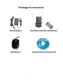
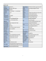
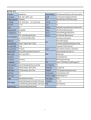
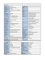
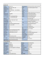
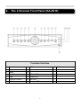
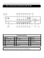
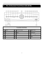
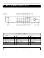
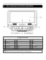
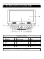
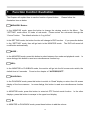
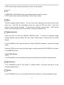
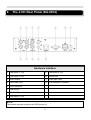
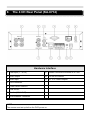
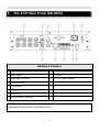
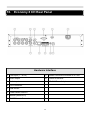
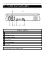
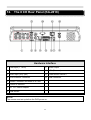
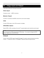
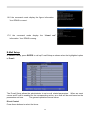
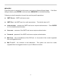
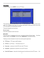
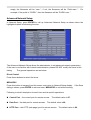
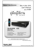
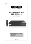
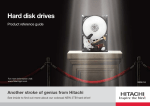
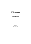
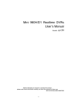
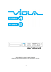
4-CH & 8-CH Digital Video Recorder
Quick Installation Guide
Version: 1.4
WARRINGS, CAUTION & COPYRIGHT
WARINGS
Reduce the risk of fire or electric shock. And do not expose this product to rain.
Do not insert any metallic object through ventilation grills.
CAUTION
The lightning flash with arrowhead symbol,
within an equilateral triangle, is intended to
The exclamation point within an equilateral
rhombus is intended to alert the user to the
alert the user to presence of insinuated
“dangerous voltage” within the products
enclosure that may be of sufficient magnitude
presence of important operating and
maintenance (servicing) instruction in the
literature accompanying product.
to constitute a risk of electric shock to
persons
RISK OF ELECTRIC SHOCK DO NOT OPEN
TO REDUCE TE RISK OF ELECTRIC SHOCK
DO NOT REMOVE COVER (OR BACK).
NO USER-SERVICEABLE PARTS INSIDE
REFER SERVICING TO QUALIFIED SERVICE
USER OF THE SYSTEM ARE RESPONSIBLE FOR CHECKING AND COMPLYING WITH ALL FEDERAL,
STATE, AND LOCAL LAWS AND STATUTES COIPCERNING THE MONITORING AND RECORDING OF
VIDEO AND AUDIO SIGNAL.
ULTRAK SHALL NOT BE HELD RESPONSIBLE FOR THE USE OF THIS
SYSTEM IN VIOLATION OF CURREENT LAWS AND STATUTES.
1)
The apparatus shall not be exposed to dripping or splashing and that no objects filled with liquids,
such as vases, shall be placed on the apparatus.
2)
CAUTION-Danger of explosion if battery is incorrectly replaced.
Replace only with the same or equivalent type.
3)
The apparatus with CLASS I construction shall be connected to a MAINS socket outlet with a
protective earthing connection.
4)
The batteries installed shall not be exposed to excessive heat such as sunshine, fire or the like.
5)
The plug or appliance coupler shall remain readily operable for the purpose of disconnection from
the mains
Package Accessories
Power Adaptor
IR Remote Controller and Batteries
USB Mouse
Software/Operation manual CD
1
1. Specification
2
3
4
5
6
7
2. The 4 Channel Front Panel (KA-6614)
Function Interface
1
Search
8
2
Copy
9
SEQ
+
3
Mode
10
-
4
Play / Pause
11
MENU /ESC
5
Stop
12
Power LED
6
Direction Control
13
Rec LED
7
CALL
14
Network LED
15
8
IR Receiver
3. The 4 Channel Front Panel (KA-6714)
Function Interface
1
ENTER
8
Mode
15
Channel 2
2
Direction Control
9
QUAD/CALL
16
Channel 1
3
Recording
10
17
USB Backup
4
Play / Pause
11
MENU /ESC
+
18
Power LED
5
Stop
12
-
19
Network LED
6
Search/ Copy
13
Channel 4
20
IR Receiver
7
SEQ
14
Channel 3
:
NOTE:
The BACKUP function means the COPY function in the DVR setting
9
3. The 8 Channel Front Panel (KA-6618)
Function Interface
1
Search
8
Direction Control
15
MENU /ESC
2
Copy
9
Mode
16
IR Receiver
3
FR
10
PAGE
17
Power LED
4
Stop
11
PTZ/CALL
18
Rec LED
5
Play / Pause
12
19
Network LED
6
FF
13
SEQ
-
20
USB
7
REC
14
+
10
4. Economy 8 Channel Front Panel
Function Interface
1
ENTER
8
Search
15
SEQ
2
Direction Control
9
Copy
16
Mode
3
Recording
10
MENU /ESC
17
USB Backup
4
Fast Forward
11
+/LIVE Display
18
Power LED
5
Play / Pause
12
-/QUAD Playback
19
Network LED
6
Stop
13
Page
20
IR Receiver
7
Fast Rewind
14
Call/PTZ
:
NOTE:
BACKUP function also can be copy function to copy DVR setting.
11
5. The 4 Channel Front Panel (KA-2814)
Function Interface
1
Power LED
8
CALL/PTZ
15
Copy /Search
2
IR Receiver
9
16
REC
3
Channel 1
10
Direction Control
-
17
Stop
4
Channel 3
11
+
18
HDD LED
5
Channel 2
12
SEQ
19
Network LED
6
Channel 4
13
Mode
20
LCD Panel
7
MENU /ESC
14
Play / Pause
21
Speaker
NOTE:
:
The BACKUP function means the COPY function in the DVR setting
12
6. The 8 Channel Front Panel (KA-2818)
Function Interface
1
Power LED
8
CALL/PTZ
15
COPY
2
IR Receiver
9
16
REC
3
Search
10
Direction Control
-
17
STOP
4
FR
11
+
18
HDD LED
5
PAGE
12
SEQ
19
Network LED
6
FF
13
Mode
20
LCD Panel
7
MENU /ESC
14
Play / Pause
21
Speaker
:
NOTE:
The BACKUP function means the COPY function in the DVR setting
13
7. Function Control Illustration
The Chapter will explain How to use the function of panel button.
illustration item as below:
Please follow the
MENU/ESC Button:
In the MONITOR mode, press the button to change the viewing mode to the Menu. The
“SETTING” mode offers 10 kinds of sub-mode. Please select the sub-mode through the
“Control” button. The default selection is “Log In/Out”.
In the SETTING mode, the button function will change to ESC function.
in the “SETTING” mode, then will go back to the MONITOR mode.
modification automatically.
If you press the button
The DVR will record all
MODE :
In the MONITOR mode, press this button to select between live mode and playback mode.
some dialogs, this button is used as a miscellaneous function key.
In
SEQ :
In the MONITOR or PLAYBACK mode, the monitor will go into the full screen auto switch; the
default time is 2 seconds.
Found on the chapter of “AUTOSEQ SET”.
QUAD/CALL:
In the PLAYBACK mode, press this button to switch to “Quad” display or return from full screen
display of the focus camera. In some dialogs, this button is used as a miscellaneous function
key.
In MONITOR mode, press this button to enter/exit PTZ Control mode function.
displays, press this button to escape to the upper level display.
+
In MONITOR or PLAYBACK mode, press these buttons to add the volume.
14
In the other
In PTZ control mode, press these buttons to zoom out the camera.
–
In MONITOR or PLAYBACK mode, press these buttons to less the volume.
In PTZ control mode, press these buttons to zoom in the camera.
Rec:
The DVR support multiple working. You can view, record, playback and remote control at the
same time. The DVR will automaticity record the image on DVR boot finish. Press this
button to force manual recording. To stop manual recording, press it again. (REC will be
shown on the lower-right corner of the screen if manual recording is ON).
SEARCH/COPY:
Press this button to enter the SEARCH SETTING mode.
To search the playback image
through different method: Search By Time, Event, Smart Search, Archived Files and POS
Search.
In the PLAYBACK mode, press the button to pop-up BACKUP windows to copy the recording
image.
Press the STOP button to stop recording image, and then press the LIVE DISPLAY to go back
to the MONITOR mode.
F.R/F.F Button
In the PLAYBACK mode the button will support the Fast Rewind and Fast Forward function
PLAY/Pause:
In the PLAYBACK mode of “Play State” or “Rewind State”, it can play and pause on the
recording image directly.
STOP:
In the PLAYBACK mode, you can press the Stop button anytime to stop the playback image.
15
MOUSE RIGHT KEY:
You can be click the mouse “right-click” used as MENU/ESC key.
16
8. The 4 CH Rear Panel (KA-6614)
Hardware Interface
1 CAM Input (1 CH)
9
2 CAM Input (3 CH)
10 Monitor Out
3 Audio Output
11 Audio input (IN2)
4 Audio input (IN1)
12 RJ45 Ethernet Connecter
5 VGA Connecter
6 USB Mouse
7 DC 12 V Power Adapter
8 CAM Input (2 CH)
NOTE:
:
The mouse must set up before the DVR power on.
17
CAM Input (4 CH)
9. The 4 CH Rear Panel (KA-6714)
Hardware Interface
1 CAM Input (1~4 CH)
9
2 Audio Output
10 3.5 mm IR Receive
3 Audio input
11 DC 12 V Power Adapter
4 VGA Connecter
5 Power Switch ON/OFF
6 USB Mouse
7 Moniter (MAIN OUT)
8 RJ45 Ethernet Connecter
:
NOTE:
The mouse must set up before the DVR power on.
18
RS485 Connecter and Alarm 4 in 2 out
6. The 8 CH Rear Panel (KA-6618)
Hardware Interface
1 CAM Input (1 CH~8CH)
9
2 Audio Output
10 IR extend
3 Audio input (IN1~IN2)
11 DC 12 V Power Adapter
4 VGA Connecter
5 Power switch
6 USB Mouse
7 Monitor Out
8 RJ45 Ethernet Connecter
NOTE:
:
The mouse must set up before the DVR power on.
19
Alarm 4 in 2 out / RS-485
10. Economy 8 CH Rear Panel
Hardware Interface
1 CAM Input (1~8 CH)
9
2 Audio Output
10 3.5mm IR Receive
3 Audio input
11 DC 12 V Power Adapter
4 VGA Connecter
5 USB Mouse
6 Power Switch ON/OFF
7 Moniter (MAIN OUT)
8 RJ45 Ethernet Connecter
20
RS485 Connecter and Alarm 4 in 2 out
11. The 4 CH Rear Panel (KA-2814)
Hardware Interface
1 CAM Input (1 ~4CH)
9
2 Monitor Out
3 Audio input (IN1) (IN2)
4 RJ45 Ethernet Connecter
5 VGA Connecter
6 USB Mouse
7 DC 12 V Power Adapter
8 Audio Output
NOTE:
:
The mouse must set up before the DVR power on.
21
USB Connect
12. The 8 CH Rear Panel (KA-2818)
Hardware Interface
1 CAM Input (1 ~8CH)
9
2 Monitor Out
10 VGA (Reserve)
3 Audio input (IN1) (IN2)
11 Power Switch ON/OFF
4 RJ45 Ethernet Connecter
12 USB Connecter
5 RS485 Connecter and Alarm 4 in 2 out
6 3.5mm IR Receive
7 DC 12 V Power Adapter
8 USB Mouse
NOTE:
:
The mouse must set up before the DVR power on.
22
Audio Output
13. Image Input and Output
The DVR provides 4CH video input and output.
Video Input
Cameras connect
to BNC connectors.
Monitor Output
Connect TV monitors to the BNC connector for main monitor display.
VGA
Connect VGA monitor to the VGA connector for display.
NTSC/PAL Switch
Select NTSC or PAL according to the local TV system.(adjust switch inside the main board)
NOTE:
:
You must select the DVR system before DVR booting.
system, please power off the DVR first.
If you want to change the DVR
Network
You can view the DVR image through “IE browser” for remote control and remote recording
function.
Connect this unit to a 10/100Base-T Ethernet network through this port.
23
14. Monitor Display Illustration
MONTOR Mode
12
1
10
9
11
8
3
7
6
5
2
4
MONITOR Mode Display illustration
Number
Item
Camera explanation
1
Camera name
Image name of display
2
Date / Time
Show the real time date and time information.
Scrolling Banner
It will show the status of motion, alarm, V. loss, HDD and
DVR state.
4
Normal Rec Size
Normal recording percentage
5
Alarm Rec Size
Alarm recording percentage
6
Audio
enable the audio function
7
Digital Zoom
enable the digital zoom x2/x4 function
8
Rec
The force manual recording mode
9
SEQ Sign
enable the SEQ function
10
Record Status
Icon means under recording mode
11
Motion Status
Icon means under motion mode
12
Alarm Status
Icon means alarm connection
3
24
PLAYBACK Mode
1
10
11
9
8
3
7
6
5
2
4
PLAYBACK Mode Display illustration
Number
Item
Explanation
1
Camera name
The playback recording image name
2
Date / Time
Show the real time date and time information.
Scrolling Banner
It will show the status of motion, alarm, V. loss, HDD and DVR
state.
4
Normal Rec Size
Normal recording percentage
5
Alarm Rec Size
Alarm recording percentage
6
Audio
Enable the audio function
7
Digital Zoom
Enable the digital Zoom x2/x4
8
Rec
The force manual recording mode
9
Backup State
The backup function mode
10
Playback Sign
Enable all playback functions
11
Date / Time
Show the recording date and time information.
3
25
MENU SETTING Mode
3
2
4
1
5
9
6
8
7
MENU SETTING Mode Display illustration
Number
Item
Explanation
1
Log In/Out
Login the DVR through the account
2
System info
Show the DVR system information
3
Video Adjustment
Adjust the camera setting
4
VGA Display
Adjust the VGA setting
5
Backup
Use the backup function
6
Setup
Enter the SETTING Mode
7
Firmware
Update the DVR firmware through USB Flash
8
Shutdown
Power off the DVR
9
Exit
Leave the MENU SETTING mode
26
SETUP SETTING Mode
7
2
3
1
4
5
8
9
12
10
11
6
SETUP SETTING Mode Display illustration
Number
Item
Explanation
1
Camera Group
Set up the DVR resolution, PTZ and Watermark
2
Camera
Set up the camera info, motion, quality and fps
3
Alarm
Set up the extra alarm function
4
SEQ Display
Set up the SEQ setting
5
Schedule Rec
Set up the alarm, motion or always recording
6
HDD
Set up the HDD recording and figure
7
Password
Manage the DVR’s account
8
System
Set up the DVR time and language
9
RS485
Set up the RS485 figure
10
Network
Set up the IP, DDNS, mail and FTP function
11
Factory Default
Reset DVR default setting
12
Exit
Leave the SETUP SETTING mode
27
SEARCH Mode
2
1
3
4
6
5
SEARCH Mode Display illustration
Number
Item
Explanation
1
Time Search
Select the date and time to playback recording image
2
Event Search
Select the event to playback recording image
3
Smart Search
Choice the motion area to playback the recording image
4
Archive Search
Search the backup device recording image
5
POS Search
Define the keyword of pos recording data for playback
6
Exit
Leave the SEARCH mode
28
15. Mouse Control Illustration
When installing and using the mouse interface, the main menu interface will be needed to
operate with mouse.
6
7
5
8
4
9
3
10
2
11
12
1
15
13
16
14
Mouse Control Illustration
1
Menu
9
PTZ Setup
2
Search
10
Mode
3
ESC
11
Alarm Reset
4
In The PLAYBACK Control
12
Scheduled Record
5
Backup
13
GPS/POS/ OSD Display
6
Split-Window Display ( 7 mode )
14
X2
7
SEQ
15
Adjust Volume
8
Switch Bar
16
Single Display the camera channel
29
16. Audio Input and Output
Connect audio IN or OUT devices through RCA interface.
Audio Input
These RCA connectors accept audio signals supplied from external devices.
Audio Output
These connectors supply audio signals to external devices.
from AUDIO OUT during playback.
Recorded audio will be supplied
NOTE:
:
The Audio function cannot guarantee power issue.
Please notice whether the microphone
spec can use or not.
17. Other Interface
The DVR have some application function for User.
Please see the illustration as below:
USB Connector (Rear panel)
Connect the USB mouse to this connection.
USB Connector (Front panel)
Connect this port to USB 2.0 compatible storage device, such as USB 2.0 disk drive,
DVD+RW, , etc.
PTZ Device:
RS-485 Connector
Connect this connector to RS-485 compatible PTZ camera(s) or keyboard.
Please set the
Selector Switch correctly.
If must join two pieces PTZ of the above, Need to use the parallel way to join PTZ.
30
Alarm IN and OUT:
The DVR can work TTL/COMS alarm signal for the LOW & HIGH of potential or the N.O & N.C
state.
ALARM INPUT:
:
Support 4 ch alarm input. The extra device connects one for the alarm input, the other for
GND.
Connect these connectors to external devices such as sensors or door switches.
ALARM OUTPUT:
:
Support 2 alarm output.
Connect these connectors to 1 Normally Closed (NC) alarm outputs
and 1 Normally Open (NO) alarm outputs. Because of the DVR cannot supply any power for
extra device, you can connect the power adapter through COM to provide electric power. When
alarm trigger, the alarm output will work.
RS-485:
In SETUP SETTING Mode, press Direct Control button to change the highlighted option to
RS-485, and then press ENTER to call up RS-485 Setup as shown.
31
18. DVR Quick Setup Guide:
This quick start guide will help you become familiar with our DVR in a very short time.
How to play basic PLAYBACK function:
In the search menu, select “Search by Time”
Then set Year, Month, Date, Hour, Minute,
execute “PLAY”.
How to quick setup RECORD function:
Select “SETUP” of the main menu.
Select “Camera”
Set each channel of “Title, Record Quality,
Record Fps.”
Confirm this setting and save.
32
How to setting MOTION function:
Select “SETUP” of the main menu.
Select “Camera”
Select Detection to enter the “Settings”
Into Motion mode.
In the Motion mode, press “+/-” button to enlarge or reduce the area.
33
Press the button to set/reset the whole video area
Press the button to test the motion detection of the camera
Choose the area where you want to displace, Click “ESC” to save this config setup
34
19. Network:
In SETUP SETTING Mode, press Direct Control button to change the highlighted option to
Network, and then press ENTER to call up Network Setup as shown.
The Network Setup allows the administrator to setup all Ethernet network related parameters.
Please check with your network administrator to set these parameters correctly.
The general operations are as below:
Direct Control
Press these buttons to select the items.
MENU/ESC
Press this button to escape from this screen, and return to Setup Menu display.
If the Save
dialog is shown, press ENTER to exit and save, MENU/ESC to exit without saving.
Following is a brief description for each item and its specific operations:
Net Type – Static IP, PPPoE, or DHCP. DHCP can only be used for intranet (LAN) access,
while Static IP and PPPoE can be used for both internet & intranet access. Press +/buttons to change the Net Type.
IP Address – Ethernet IP address for the system.
contact your local ISP (Internet Service Provider).
35
To get the static IP address, please
Net Mask – Net Mask for the IP address.
Gateway – Gateway IP address for the system.
DNS – DNS (Domain Name Server) IP address for the system.
Username – PPPoE username for the system if PPPoE is used.
Password – PPPoE password for the system if PPPoE is used.
DDNS Type – Dynamic, Static, Custom DDNS (Dynamic Domain Name Server) type, etc.
Please contact your local DDNS Service Provider to get the DDNS URL, username, and
password.
Press +/- buttons to change this item.
URL – the URL (Uniform Resource Locators) for the system if PPPoE is used.
DDNS Username – DDNS username for the system if PPPoE or Static IP is used.
DDNS Password – DDNS password for the system if PPPoE or Static IP is used.
NOTE:
:
If DDNS Type is Free DNS, the URL must be appended with “,hash”, where hash is extracted
from the grab URL batch file that is downloaded from freedns.afraid.org
DDNS Application
The DDNS service will provide the function. The domain name corresponds with IP address.
But you need to apply for account from DynDns.org website. The DynDns.org website
provides the free service to the world’s user. This chapter will teach the step by step method,
please follows the function illustration as below:
1. Please input the “DynDns.org” website
(http://www.dyndns.com/) on Internet Explorer
then click the “Connect” button.
36
2. If you have the account in the DynDns.org, you
can skip the illustration to no.9. However, if you
don’t have the account, please click the “Create
Account” button through the left-mouse.
3. You will see the table of account, and then input the needful information such as: “User
Information” and “Terms of Service”. You can input other information by yourself.
1
2
4. After input finish, please click the “Create Account” button.
If the data is right, the website
will display the “Account Created” information
5. You will receive the check mail from DynDns.org. Please check
your mail. If you receive the mail, please visit the confirmation
address to complete the account creation process.
37
6. Click the red square to finish the creative account.
7. You can login to DynDns.org, please input the
username and password on main webpage. And
click the “Service” button to set up the DDNS
function.
8. Please select the “Dynamic DNS” button.
9. Click the “Get Started” button to add the new Hostname.
38
10. Set up the “Hostname” and “IP Address” by yourself. You can enter your favor domain
name to “Hostname”, and input correct “IP address” to IP Address. Finally, click the “Add
Host” to finish the setting.
11. The DDNS information will display on the webpage in the end.
12. Please try to connect to the DVR through domain name.
13. If you cannot connect the DVR through domain name, you can test the DDNS service on
your PC.
14. Please open the “command mode” from “Start Menu”.
15. Input the command: c:\>ping xxxxx.dyndns.org [ENTER].
:
NOTE:
The “xxxxx” is your domain name.
39
16. If the command mode display the figure information.
Your DDNS is correct.
17. If the command mode display the “timed out”
information. Your DDNS is wrong.
E-Mail Setup:
In Network Setup, press ENTER to call up E-mail Setup as shown when the highlighted option
is E-mail.
The E-mail Setup allows the administrator to set e-mail related parameters. When an event
occurs and E-mail is enabled for the corresponding action, an e-mail will be sent based on the
parameters set here.
The general operations are as below:
Direct Control
Press these buttons to select the items.
40
MENU/ESC
Press this button to escape from this screen, and return to Network Setup display.
If the Save
dialog is shown, press ENTER to exit and save, MENU/ESC to exit without saving.
Following is a brief description for each item and its specific operations:
SMTP Server – SMTP mail server name.
SMTP Port – the SMTP port for e-mail transmission. The default value is 25.
Authentication – whether the SMTP mail server requires authentication. Press ENTER
or +/- to check/uncheck this item.
Username – username if the SMTP mail server requires authentication.
Password – password if the SMTP mail server requires authentication.
Mail From – the e-mail address of this DVR unit, i.e. the sender of the e-mails originated
from the triggered events.
Mail To #1-5 – the receivers’ e-mail addresses. The system can send the e-mails
originated from the triggered events to up to 5 different receivers.
41
FTP Setup:
In Network Setup, press ENTER to call up FTP Setup
The FTP Setup allows the administrator to set FTP related parameters. When an event occurs
and FTP is enabled for the action, the recorded video/audio for that event will be sent to the
FTP server based on the parameters set here.
The general operations are as below:
Direct Control
Press these buttons to select the items.
MENU/ESC
Press this button to escape from this screen, and return to Network Setup display.
If the Save
dialog is shown, press ENTER to exit and save, MENU/ESC to exit without saving.
Following is a brief description for each item and its specific operations:
FTP Server – FTP server web/IP address.
FTP Port – the FTP port.
Username – username for this DVR unit in the FTP server.
Password – password for this DVR unit in the FTP server.
Prefix Of Filename – the prefix of the filenames for the files sent to the FTP server.
The default value is 21.
42
If it’s
empty, the filenames will be “cam..”; if not, the filenames will be “Prefix-cam..”.
For
example, if the prefix is “DVR01”, then the filenames will be “DVR01-cam..”.
Advanced Network Setup:
In Network Setup, press ENTER to call up Advanced Network Setup as shown when the
highlighted option is Advancing function.
The Advanced Network Setup allows the administrator to set advanced network parameters.
If the user is not familiar with network administration, please DO NOT modify the items in this
dialog.
The general operations are as below:
Direct Control
Press these buttons to select the items.
MENU/ESC
Press this button to escape from this screen, and return to Network Setup display.
If the Save
dialog is shown, press ENTER to exit and save, MENU/ESC to exit without saving.
Following is a brief description for each item and its specific operations:
Control Port – the control port for remote access.
The default value is 67.
Data Port – the data port for remote access. The default value is 68.
HTTP Port – the HTTP (web page) port for remote access. The default value is 80.
43
WAP Picture Quality – the WAP picture quality if WAP access is supported for the DVR.
Press +/- buttons to change the value.
IP Filter #1-4 – the IP filters #1-4 for remote access.
Only those PCs with IP addresses
matching one of the IP filters can access the DVR remotely.
NOTE:
:
If the Control Port or Data Port is not available or accessible during remote access, the system
will reset the ports to their default values, i.e. 67/68.
Factory Default:
The DVR can repeat to get the factory default figures through this function. Press the
“Direction Control” button to reset the DVR to factory default figure. You also can use the
mouse to do it.
NOTE:
:
When you want to reset the default setting, the DVR will pop-up the confirmation window to
check again with customer.
44
20. USB / DVD Playback
After the backup image finish, the USB flash/DVD will
include the “SelfPlayer” software and backup recording
image file. You can direct to view the backup image
through PC/Laptop.
You need to plug the USB
flash/DVD into PC, and then open the disk of USB
flash/DVD.
Click "SelfPlayer.exe" to execute the DVR software
Click the “File” area then click the “Open" button to select
the backup recording file. Open the USB/DVD disk
located driver letter. (Example F:). The Backup file
default name is the “0001”.
After select the backup recording file,
the DVR will automatically play the image.
Click the channel to display the full image on the monitor
45
21. Remote view
You can remote view the image of DVR through internet on the world. Just input the IP
address or domain name on “I.E Browser”. The remote function would support viewing image,
playback image and recording image.
System Requirements of Remote PC
It is recommended to access the digital video/audio recorder using a PC that meets the
following system requirements.
PC
IBM PC/AT compatible with Intel® Pentium® 4, 1.7 GHz or above CPU.
OS
MicroSoft® Windows® XP, Windows® 2000 with SP4, or Windows® Vista.
Monitor
1024 x 768 or above.
Memory (DRAM)
512MB, or 1024MB for Windows® Vista.
Web Browser
MicroSoft® Internet Explorer® 6.0 or above.
DirectX
MicroSoft® DirectX® 9.0 or above.
Others
Windows XP KB319740 Package if Windows XP SP2 is installed.
46
DirectX® End-User Runtime 9.0
It has been installed in your PC successfully.
download of it.
If not, please logon to web page to get the free
NOTE:
:
Web Page:
http://www.microsoft.com
Windows XP KB319740 Package
It has been installed in your PC successfully if the PC is running Windows XP SP2. If not,
please logon to web page to get the free download of it, or install it from the corresponding
directory in the CD.
(This package is a bug fix for Windows XP SP2.)
NOTE:
:
Web Page:
http://www.microsoft.com/downloads/details.aspx?FamilyId=9B5EDFC8-A4BB-4080-9063-651
8166E2DAB&displaylang=en
The VGA Setting from PC/Laptop
Please go to Start->Setup->Control, select Display->Settings, and set the Screen Resolution to
at least 1024x768 and Color to 32-bit.
47
You need to change the security setting of I.E Browser.
Please follow the step by step
illustration as below:
Open the I.E Browser select the “Tools” “Internet
Options”.
Select the “Security” bookmarker Custom Level Security
Settings
NOTE:
:
The domain name or IP address of the digital video/audio recorder has been set as trusted
web site in your PC, and the (https:) server verification for trusted web site is unchecked. If
not, please go to Tools->Options->Security in your I.E. to do the settings. For I.E. 7, please
set the Security level for this zone to Low.
48
Enabled or Prompt the selection of Download unsigned
ActiveX controls, and then click the “OK” button to leave
setting.
Open the I.E Browser and input the IP address or domain
name of DVR.
Press the “connect” button.
The I.E Browser will pop-up the window, please click the
“Install” button to set up the software of ActiveX. After install
finish, the Internet Explorer pop-up the window again.
Please input the user name and password to enter the
network viewing mode.
NOTE:
:
The default username is “abc”. However, the default password is “123”. The account is the
same the DVR account
49
After the above-mentioned items have been done correctly, restart your web browser and enter
the domain name or IP address (EX. http://192.168.1.100 if HTTP port is 80, or
http://192.168.1.100:800 if HTTP port is 800) of the digital video/audio recorder in the
Location/Address field of the web browser. The plug-in software in the system will be
downloaded and run automatically in the web browser.
NOTE:
:
Please note that up to 8 users can logon this DVR simultaneously.
The video images can be displayed in several types of split-window screens, including
1/4/9/16-Window for single DVR and 25/36/49/64 for multiple DVRs. And the focus window is
surrounded by a frame border. In addition to the video windows, there are different icons on
the lower corner and the right corner of the screen for status display and control.
NOTE:
:
The “.L” following the camera title stands for Live display, “.P” for Playback, and the camera
title with white background has detected motion.
NOTE:
:
The frame rate is limited by the bandwidth of the network and the pre-record IPS of the
camera
The picture quality depends on the recording resolution and recording quality of the camera
About the IPS and quality setting please make reference to the chapter of Camera.
When the user leaves I.E., you may be asked to save changes to files, please click on OK or
Yes to save the changes. The operations and descriptions for these icons are as below:
50
In video window, right-click the mouse button to call up Camera/Playback/Print Dialog.
(Left)
click on Playback or Camera number to change the window to the corresponding camera and
live/playback mode. The user may also click on the “Print” button to print the video to the
printer, or “Snapshot” the video.
22.
Support GPS / POS
The DVR can support all GPS / POS on the market.
Please reference to the details manual in the CD.
23.
Support Hardware List
There are many HDD spec. Please suggest the list to buy the applicable hardware that
combine with the DVR. The DVR can support the HDD size until 2TB.
HDD Factory
WD
Hitachi
Type
Size
WD1600AVJS
160 GB
WD2500AVJS
250 GB
WD3200AVJS
320 GB
WD5000AVVS
500 GB
WD6400AVVS
640 GB
WD7500AVVS
750 GB
WD10EVVS
1 TB
HDP725016GLA380
160 GB
HDP725025GLA380
250 GB
HDT721032SLA360
320 GB
HDP725050GLA360
500 GB
HDT721064SLA360
640 GB
HDS721075KLA330
750 GB
HDT721010SLA360
1 TB
NOTE:
:
The DVR almost support all HDD on the market. The list is the reference data for user.
51
Appendix C:
24.
Support USB Flash and DVD List
Support USB Flash and DVD List
There are many USB Flash and DVD spec.
Please suggest the list to buy the applicable
hardware that combine with the DVR.
Type
Format
USB-Storage Enclosures 5.25”
Macpower’s Alumni Prefect USB 2.0 - PF-U2MS.
Transcend’s JetFlash 150/V60 Series,
Apacer’s Handy Steno AH220,
USB-Disk Storage
Pretec’s
i-Disk Wave 512M-Black
Kingston’s Data Traveler USB Flash Driver(DTI/512FE)
SanDisk’s Cruzer micro USB Flash Driver
Sony’s MICRO VAULT Classic Series
Asus DRW-1608P Series
DVD Writer
Pioneer DVR-A11, DVR-X152 Series
BenQ EW200G Series
LITEON Light Scribe DVD Writer SHM-165H6S,
20X DVD Writer DX-20A4P
Sony DVD/CD Rewritable Drive Model DRX-810UL Series
NEC DVD/CD Rewritable Drive Model ND-4550A Series
HP dvd9404e External 18X Super Multi DVD Writer Series
Infomedia DVD+R 16X
Mitsubishi DVD+RW 1-4X
Philips DVD+RW 1-4X
Ritek DVD-R 8X
Ritek DVD+RW 1-4X
Verbatim DVD+RW 1-4X
52
25.
PDA / Mobile Phone Remote Access
The digital video/audio recorder can also be remotely accessed by using a web browser
installed on a PDA or mobile phone.
(1) Supports xHTML and MJPEG file format
(2) The screen resolution will at 240x320 or above.
(3) Support i-phone / Firefox / Symbian 6.0 / Apple / Linux / Windows Mobile
Please enter the domain name or IP address of the digital video/audio recorder in the
Location/Address field of the web browser, and the remote login display will be shown.
For most of the mobile devices, the DVR will automatically redirect to the correct web page, EX.
http://192.168.1.89/wap.htm for IP address http://192.168.1.89.
If not, please enter the full address with /wap htm The use may need to enter
http://192.168.1.89:800/wap.htm if HTTP port has been changed to 800.)
Please enter the correct login name and password for the digital video/audio recorder to login
the system, and the screen will be shown as below.
53
26.
Firefox browser Remote Access
Users want to use Firefox browser to access the system, make sure that the following:
1. Execute Firefox.
2.
3.
4.
5.
Login “http://ietab.mozdev.org” web,
Select Tools>IE Tab option.
Select Sites Filter.
Select “Sites list here will always render using embedded IE”,and add the s
http://xxx.xxx.xxx.xxx/ie.htm sites to the local pc.
6. Enter DVR path http://xxx.xxx.xxx.xxx/ie.htm
54