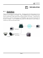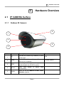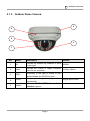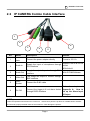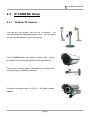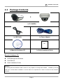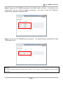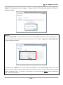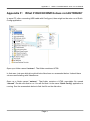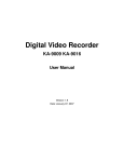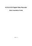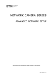
1
IP Camera User Manual Version: 1.1 Date: 10 30, 2008 WARRINGS, CAUTION & COPYRIGHT WARINGS Reduce the risk of fire or electric shock. And do not expose this product to rain. Do not insert any metallic object through ventilation grills. CAUTION The lightning flash with arrowhead symbol, The exclamation point within an equilateral within an equilateral triangle, is intended to rhombus is intended to alert the user to the alert the user to presence of insinuated presence of important operating and “dangerous voltage” within the products maintenance (servicing) instruction in the enclosure that may be of sufficient magnitude literature accompanying product. to constitute a risk of electric shock to persons RISK OF ELECTRIC SHOCK DO NOT OPEN TO REDUCE TE RISK OF ELECTRIC SHOCK DO NOT REMOVE COVER (OR BACK). NO USER-SERVICEABLE PARTS INSIDE REFER SERVICING TO QUALIFIED SERVICE USER OF THE SYSTEM ARE RESPONSIBLE FOR CHECKING AND COMPLYING WITH ALL FEDERAL, STATE, AND LOCAL LAWS AND STATUTES COIPCERNING THE MONITORING AND RECORDING OF VIDEO AND AUDIO SIGNAL. ULTRAK SHALL NOT BE HELD RESPONSIBLE FOR THE USE OF THIS SYSTEM IN VIOLATION OF CURREENT LAWS AND STATUTES. CONTENTS CONTENTS: □ 1. INTRODUCTION ............................................................................................... 4 1.1 ILLUSTRATION ................................................................................................................................. 4 □ 2. HARDWARE OVERVIEW ................................................................................ 5 2.1 IP CAMERA SURFACE..................................................................................................................... 5 2.1.1 Outdoor IR Camera: ................................................................................................................ 5 2.1.2 Outdoor Dome Camera: .......................................................................................................... 6 2.2 IP CAMERA COMBO CABLE INTERFACE ......................................................................................... 7 2.3 IP CAMERA SETUP ......................................................................................................................... 8 2.3.1 Outdoor IR Camera: ................................................................................................................ 8 2.4 PACKAGE CONTENTS ........................................................................................................................ 9 □ 3. IP CAMERA INSTALLATION........................................................................ 10 3.1 FIRST TIME USE INSTRUCTIONS ...................................................................................................... 11 3.2 BASIC SETTING (MINI-USB) ........................................................................................................... 12 3.3 ADVANCE SETTING (IP SCAN) ........................................................................................................ 16 □ 4. ACCESS TO IP CAMERA ............................................................................... 19 4.1 INITIAL USERNAME & PASSWORD .................................................................................................. 19 4.2 VIEWING WEB PAGE ....................................................................................................................... 20 □ 5. WEBPAGE INTERFACE SETTING .............................................................. 21 5.1 LIVE MODE .................................................................................................................................... 21 5.1.1 Live Recording: ..................................................................................................................... 22 5.1.2 Snapshot: ............................................................................................................................... 22 5.1.3 Setup: ..................................................................................................................................... 22 5.1.4 Video: .................................................................................................................................... 22 Page 1 CONTENTS 5.1.5 Audio: .................................................................................................................................... 23 5.1.7 Camera Information: ............................................................................................................. 24 5.1.8 Digital Output: ....................................................................................................................... 24 5.2 SETUP MODE .................................................................................................................................. 25 5.2.1 Status: .................................................................................................................................... 26 5.2.2 Network: ................................................................................................................................ 27 STATIC IP ............................................................................................................................. 28 Dynamic IP (DHCP) .............................................................................................................. 29 PPPoE .................................................................................................................................... 30 5.2.3 Video: .................................................................................................................................... 31 Video Setting ......................................................................................................................... 32 Color Settings ........................................................................................................................ 34 Max Client Limit ................................................................................................................... 35 5.2.4 Event Rule: ............................................................................................................................ 36 Trigger and Handler (INPUT) ............................................................................................... 37 Trigger and Handler (OUTPUT) ........................................................................................... 39 5.2.5 Schedule Capture: .................................................................................................................. 41 Schedule capture .................................................................................................................... 41 5.2.6 Date & Time: ......................................................................................................................... 42 Time Zone.............................................................................................................................. 42 Client PC Time ...................................................................................................................... 42 Time Server ........................................................................................................................... 42 5.2.7 OSD: ...................................................................................................................................... 43 Text Color .............................................................................................................................. 43 OSD Position ......................................................................................................................... 43 Time ....................................................................................................................................... 44 Channel Name ....................................................................................................................... 44 5.2.8 Port: ....................................................................................................................................... 44 Web ........................................................................................................................................ 44 Video + Audio........................................................................................................................ 44 5.2.9 DDNS: ................................................................................................................................... 45 IPv4 DDNS ............................................................................................................................ 45 Dyndns.org ............................................................................................................................ 45 5.2.10 SMTP/FTP:.......................................................................................................................... 46 Remote SMTP Setup ............................................................................................................. 47 Remote FTP Setup ................................................................................................................. 47 5.2.11 Trigger Setup: ...................................................................................................................... 48 Digital Input........................................................................................................................... 48 Periodic Timer ....................................................................................................................... 49 Motion Detection ................................................................................................................... 49 Page 2 CONTENTS 5.2.12 Pre/Post Setting: .................................................................................................................. 50 5.2.13 Account: .............................................................................................................................. 51 Account Limitations .............................................................................................................. 51 Guest Permissions ................................................................................................................. 51 5.2.14 Security: ............................................................................................................................... 52 Security Level ........................................................................................................................ 52 Power LED ............................................................................................................................ 52 5.2.14 Maintenance: ....................................................................................................................... 53 Language ............................................................................................................................... 53 Firmware update .................................................................................................................... 53 System Configuration (Backup/Restore) ............................................................................... 53 Logo Upload .......................................................................................................................... 53 5.2.15 Factory Default: ................................................................................................................... 54 5.2.16 Reboot: ................................................................................................................................ 54 5.2.17 Logout: ................................................................................................................................ 54 APPENDIX A: HOW TO SET UP THE ALARM INPUT & OUTPUT ............................................................... 55 APPENDIX B: HOW TO SET UP YOUR PC IP INFORMATION ..................................................................... 56 APPENDIX C: APPENDIX C: APPENDIX E: APPENDIX F: THE IP CAMERA FIRMWARE UPGRADE ......................................................................... 58 DDNS APPLICATION....................................................................................................... 59 HOW TO SET UP IP CAMERA THROUGH ROUTER ........................................................... 63 WHAT IF OUICKCONFIG DOES NOT AUTORUN? ....................................................... 67 Page 3 1. □ 1. □ Introduction Introduction 1.1 Illustration Thank you for choosing our company products. We also produce the analog camera, but now we built in the IP module on our camera. Plug IP CAMERA directly to a RJ45 Ethernet port and you will be able to watch camera sites real-time anywhere in the world. Furthermore you will be able to control the camera from any PC/Notebook over the Internet through the I.E browser or Software. Our IP CAMERA also provide the USB interface to quick setting for customer, you will set up all function easily. Page 4 2. □ 2. □ Hardware Overview Hardware Overview 2.1 IP CAMERA Surface 2.1.1 Outdoor IR Camera: 4 1 2 5 3 No. Name Description 1 IR Provide the Infrared ray distance to work 50M in the night 2 Lens Provide the 3~9mm of Japan Computar 9~22mm Option Lens for our customer. 3 CDS According to the light is strong or low, enable/disable the IR LED function. 4 Cover 5 Cable Easy open Remark design to adjust Lens conveniently Refer the 2.2 IP CAMERA Combo Cable Interface capture Page 5 2. □ 2.1.2 Hardware Overview Outdoor Dome Camera: 5 4 2 3 1 No. Name Description Remark 1 IR Provide the Infrared ray distance to work 10/20M in the night 2 Lens Provide the 3~9mm of Japan Computar 9~22mm Option Lens for our customer. 3 CDS 4 Cover Easy open conveniently 5 Cable Refer the 2.2 IP CAMERA Combo Cable Interface capture According to the light is strong or low, enable/disable the IR LED function. design to Page 6 adjust Lens Burglar-proof Screw 2. □ Hardware Overview 2.2 IP CAMERA Combo Cable Interface 1 2 6 3 No. 1 Name 4 5 Description Remark DC Power Connect the power adapter directly Jack Format is 12V 1A 2 Audio In Support Line IN & mic IN Supply the input of microphone through format RCA interface With ActiveX 3 Audio Out Supply the output of sparker through RCA With IP CAM Software interface 4 Video Out The Image will output to monitor through BNC interface 5 RJ45 Socket Connect the RJ45 cable Refer 6 DI / DO the chapter of Connect the trigger in & out alarm device Appendix A: How to through DI/DO interface set up the Alarm Input & Output NOTE: Follow the operational instructions for correct use. Please don’t place the product on unstable desk or bracket. And avoid any liquid permeate inside of the machine in case damage the product. Page 7 2. □ 2.3 IP CAMERA Setup 2.3.1 Outdoor IR Camera: You can buy the bracket then set up to camera. Our camera follows the standard bracket screw. You can select the convenient bracket for your environment. The IP CAMERA base can install on ceiling, wall …Using the screws to mounting the bracket on the right position. Find screw mounting base to assemble the camera with the bracket then complete installation. Connect the power supply of DC12V / 1A Stable voltage adaptor. Page 8 Hardware Overview 2. □ Hardware Overview 2.4 Package Contents & 1 x IP CAMERA 1 x USB Cable 1 x Power Adapter QIG 1 x Manual & Software CD 1 x Quick Installation Guide Manual & Software CD: NVR Management Software User Manual Quick Installation Guide NOTE: PC running Microsoft Windows 2000 or above is only capable of running NVR software. PLEASE go through NVR users’ manual before installation to check further PC requirements in order to ensure smooth software operation Page 9 3. □ 3. □ IP CAMERA Installation IP CAMERA Installation IP Cam is the easily setting IP CAMERA. Our IP CAMERA provide two kinds of setting methods: “Basic Setting” and “Advanced Setting”. Basic Setting: You can quickly configure or have to be set to factory default settings through the mini-USB interface. Insert mini USB cable onto USB config port and connect other end to PC. When video server is powered on, port will not be operational. Because of IP CAMERA will get the power from mini-USB interface. Advanced Setting: If you do not have the USB cable, please skip this section and jump to “Advanced Setting”. You can search the IP CAMERA through IP scan software. NOTE: You can change your computer IP then using the cross-over RJ45 cable to set up the IP CAMERA. to change your computer IP first. You need If you don’t know how to set up your computer IP address, please make reference to the chapter of Appendix. B How to set up your PC IP Address information for further detailed description. Page 10 3. □ IP CAMERA Installation 3.1 First Time Use Instructions In first time, you need to check some requirement from your environment. not really, the IP CAMERA may not work. Network environment: If the requirement is Standard CAT5 Ethernet cable. Connect a standard CAT5 Ethernet cable to RJ45 socket on IP FIXED DOME CAMERA and connect other end to your network hub/switch. Make sure the PC you want to access IP CAMERA is on the same network domain. Power environment: AC 110~220V Socket. Power on video server by using power adapter provided in the product package. Connect power adapter to 110-220v AC socket. Webpage Browser Supplier: Microsoft Internet Explorer Browser Version 6 or higher. Because of the IP CAMERA need to install the OCX object(ActiveX object), Mozilla Firefox and similar others are not guaranteed to work with IP CAMERA. Factory Setting: The Default IP Address and User Info. Because of our IP CAMERA not provide the reset default button; you can set up the IP through IPScan software or mini-USB interface. Nevertheless, the IP CAMERA also has the default IP mode and address. IP Mode: Static IP IP Address: 192.168.1.2 Submask: 255.255.255.0 Gateway: 192.168.1.1 IP CAMERA owns the Default ID & Password. You also can add other user account by yourself. Please make reference to ID: root the chapter of 5.2.13 Account for further detailed description. Password: pass Page 11 3. □ IP CAMERA Installation 3.2 Basic Setting (mini-USB) Disconnect the power cable and RJ45 cable connected to the IP CAMERA. Connect the IP CAMERA to PC of using the mini-USB cable. After 5 ~ 10 seconds, you can notice “Disk drive” being detected The systems will pop-up the new window on desktop. Please click the “Config Wizard” selection then press OK. Input the password to enter the quick setting page. (ID: root (Default Setting); Password: pass) NOTE: You will be asked for password. Earlier, if you have never changed the password for user root, please type pass as the password. Then click login button. If you input wrong password, you will get this dialog box. Page 12 3. □ IP CAMERA Installation Navigate through “Quick Wizard”, click it and you will enter the next windows. You can also use the “Change Password” and “Factor Default” functions through mini-USB. Step 1: Select your connection mode by yourself then input the correction information. You can select the Static IP, DHCP and PPPoE. For example: Static IP Connection Type. Clicking next will show that settings are saved. You can click finish if you are done or go back or change other settings. Similarly you can change other settings at ease. NOTE: If you don’t know your connection type or IP information, please check the default with local ISP. Page 13 3. □ IP CAMERA Installation Step 2: Maybe the IP CAMERA connects to the HUB, Switch or Router. According to your requirement, input your static IP address information. You need to input the IP address, Subnet mask, gateway and Default DNS. Step 3: Set up your IP CAMERA port information. The default setting is 80(Web Port) and 1852(Stream Port). NOTE: The detail IP setting information, please make reference to the chapter of 5.2.1 Network for further detailed description. Page 14 3. □ Step 4: The setting is done in this page. finish the setting IP CAMERA Installation Please click the “OK” button then press the “Finish” to NOTE: Click the “Setup DDNS” to set up DDNS function, input the detail DDNS setting info. to field of DDNS Setup. If you have not the account of Dyndns.org, please make reference to the chapter of Appendix. C DDNS Application for further detailed description. You also click the “DDNS” button to finish detailed configuration on the “Quick Config” setting. button to return to Network page to setup network further after finish setting. detailed configuration page. page. Click “OK” Please choose and click next for For instance, shown below is a screen which has STATIC network configuration Click next to proceed. Page 15 3. □ IP CAMERA Installation 3.3 Advance Setting (IP Scan) If you are not using mini-USB cable, very likely your environment can use the advance setting to camera. If you have many IP CAMERAs on your office/factory, you would need to set up your camera through “Advance Setting”. Install the IP CAMERA Software first. Insert CD and install IP Surveillance Software to your PC. For CD installation, please click on Install “IPS" and follow the wizard. The system will pop-up the window of “IP Surveillance Software” then clicks the “Install IPSurveillance” icon to install the software. After the installation, you can find the “IPSurveillance” file on the “Start Menu” Click the “IPScan” to open the software then click the “Scan” button to search the IP CAMERAs. If the software finds the IP CAMERAs, you will see the camera information(IP Address and MAC) on the list. To refresh, click “Clear Table” then click “Scan” again. Page 16 3. □ IP CAMERA Installation Select the setting IP CAMERA then click “Change Setting” button to modify your IP CAMERA setting. Find out the type of your WAN port of your Internet service: fixed IP, DHCP or PPPoE. (Please ask your internet service provider (ISP) for the connection details and information) Change any settings you want to make and make sure you have correct values in all fields. Click “Apply”. NOTE: You can also double click a specific IP address and change some basic network parameters. A dialog box will appear as follows. Within 10 seconds, the dialog box should disappear to indicate new settings are accepted and being applied. Wait for around 30 seconds, before trying to refresh IP list. Click “Clear Table” and click “scan” again. You should be able to find MAC address of IP CAMERA under new IP address. IP CAMERA is online on your network. Use ping command from Windows command prompt to double check if IP is reachable. Finish all setting, quit IPScan anytime, click “Exit” Page 17 3. □ IP CAMERA Installation NOTE: If you want to quickly open the IP you see on IPScan on your browser, select an IP and do a “double right click” on your mouse/touchpad. You can see the browser window open that IP. You also change the bind IP by yourself. You can select the “ANY” or “your computer IP” Page 18 4. □ 4. □ Access to IP CAMERA Access to IP CAMERA Open the Browser through Internet Explorer or IPScan. Input the IP address of IP CAMERA then press ENTER button to open the setting web page of IP CAMERA. For example: Default IP: 192.168.1.2 Input the ID and Password to login the setting web page Default ID: root Default Password: pass Click “Login” button to go to web view. 4.1 Initial Username & Password IP CAMERA provides two basic purviews for our user: Administrator and Guest. different power as below: Administrator: Default ID: Default Password: root pass Only password is changeable. Full access right to view, control system settings. Guest accounts: ID/Password not necessary. Basic view and some action buttons can work. NOTE: Guest Permission should be enabled to see Guest icon. Page 19 See the 4. □ Access to IP CAMERA 4.2 Viewing Web Page Administrator Mode Viewer: When you log in successfully with root/pass as Administrator, the viewer screen will display as shown below. Guest Mode Viewer: Click the “Guest” to log in the guest mode. After successful log in as Guest, the viewing page will appear as follows. The “camera info” button when clicked shows FPS, camera name and resolution values. NOTE: You also can add other user account by yourself. Please make reference to the chapter of 5.2.13 Account for further detailed description. Page 20 5. □ 5. □ Webpage Interface Setting Webpage Interface Setting The chapter will explain the web page function display illustration. There are two kinds of mode: “Live Mode” and “Setup mode”. Several controls options are available on the right side. And OSD is displayed on top left corner of the screen (time, date, camera name) 5.1 Live Mode 1 2 3 4 5 6 7 Function Illustration Number Item Explanation 1 Live Recording Record live stream to local HDD 2 Snapshot Snapshot the picture to your PC 3 Setup Enter the advance setting of IP CAMERA 4 Video Set up the Resolution and Bit Rate 5 Audio Enable/Disable the Audio function 6 Camera Info Display the Camera information 7 Digital Output Remote ON/OFF the Digital Output (DO) sensor Page 21 5. □ 5.1.1 Webpage Interface Setting Live Recording: Press this icon to record live stream image to local HDD. And you can select the save path by yourself. When the record function work, the button will flash 5.1.2 Snapshot: Press this icon to snapshot the picture to local HDD. And you can select the save path by yourself. When the snapshot function is finish, you will come back the “Live Mode”. 5.1.3 Setup: Click icon located on top-right side to enter server settings page. It is a toggle button to switch between Config and viewer pages. 5.1.4 Video: You can set up the “Resolution” and “Bitrate” here. They will affect the remote video transmission. If the resolution quality is higher, the video transmission will be slowly. bitrate value. According to your network speed select the The Resolution value please following table describes resolution values for each video format. Resolution QCIF CIF D1 NTSC 176X120 352X240 720X480 PAL 176X144 352X288 720X576 Page 22 5. □ Webpage Interface Setting The Bit rates value please choose a particular value and it is applied within few seconds. Video on the screen will pause briefly. The Range:32K/64K/128K/256K/384K/500K/750K/1M/1.5M/2M/3M (bps) NOTE: If you want to see the best transmission through WAN, we refer our customer select the 256K or more. need to check the network connection speed with local ISP 5.1.5 Audio: Click the Enable check box to work. Enable or disable function for audio will result in video flicker for a second and then return back to normal. This is not an error. Page 23 But you 5. □ 5.1.7 Webpage Interface Setting Camera Information: Shows video information of the transferred data on the upper left corner of the video screen such as frame rate (fps), channel name, resolution. 5.1.8 Digital Output: If your IP CAMERA set up the alarm of DO, you can remote enable / disable the alarm function ON/OFF. Page 24 5. □ Webpage Interface Setting 5.2 Setup Mode 7 1 2 3 4 5 6 Function Illustration Number Item Explanation 1 Status Display the IP CAMERA connection status 2 Basic Provide the basic setting of IP CAMERA 3 Expert Provide the expert setting of IP CAMERA 4 Factory Default Reset the factory default setting 5 Reboot Reboot the IP CAMERA 6 Logout Leave the setting of IP CAMERA 7 Live Return to the “Live Mode” Page 25 5. □ 5.2.1 Webpage Interface Setting Status: Initial view of web Config interface is “Status” page. Hardware & Firmware information along with network status such as current IP and related details are clearly shown. NOTE: Remember to press “OK” after you have changed settings in a particular settings page which has “OK” button. After few seconds, you can see a confirmation dialog box informing that settings have been updated. Pressing OK will return to the same page. Page 26 5. □ 5.2.2 Webpage Interface Setting Network: Three configuration types are available for wired network connection: STATIC IP, DYNAMIC IP (DHCP) & PPPoE. The default mode is the STATIC IP. You can set up the IP address through Internet Browser or IPScan software. But the PPPoE mode need to enter the setting, you must input the detail information from local ISP. Page 27 5. □ Webpage Interface Setting STATIC IP The STATIC IP is the most reliable mode on IP CAMERA. Because of the IP address is always not change from ISP. You always input the IP then remote see the image through I.E Browser. You also combine with the DDNS service to set up. Always click “OK” to save changes in a particular page. Reboot is required and will be automatically triggered after you press “OK”. Wait for count down timer to finish and page will refresh automatically and you should see initial login page. NOTE: Always use IPScan to find the MAC address after reboot and double check the IP address is correct. If IP was changed in web configuration, you cannot return to initial login page after reboot. Page 28 5. □ Webpage Interface Setting Dynamic IP (DHCP) You want to allocate Dynamic IP address. The DHCP service will automatic get different IP form WAN or LAN. Please check the service by yourself. Click “OK” button. Reboot is required and will be automatically triggered after you press “OK”. Wait for count down timer to finish and page will refresh automatically and you should see initial login page. NOTE: Always use IPScan to find the MAC address after reboot and double check the IP address is correct. If IP was changed in web configuration, you cannot return to initial login page after reboot. Page 29 5. □ Webpage Interface Setting PPPoE PPPoE is used in case network supports PPPoE like xDSL. The service will automatic get different IP form ISP, but the IP will disconnect after 3 days. We suggest combining with the DDNS function. Because of you don’t know what time change the IP from ISP (Internet Service Provider). User ID / Password: Please check from local ISP. service. Normally, you got the information that you apply for the PPPoE Service Name: Service name of ISP. You can keep the blank in this value. MTU: Maximum transmission unit of data. If you don’t know the value, please keep defaulting. The default value is “1412”. DNS Server: IP address of DNS sever can be set to be created automatically. you should use DHCP. If xDSL does not use static IP, NOTE: Always use IPScan to find the MAC address after reboot and double check the IP address is correct. If IP was changed in web configuration, you cannot return to initial login page after reboot. Page 30 5. □ 5.2.3 Webpage Interface Setting Video: You can set up the video values in this page including: Video Setting and Color Setting. According to your requirement and environment, you can adjust the all values to find the best result for your IP CAMERA. Page 31 5. □ Webpage Interface Setting Video Setting Video Compression Type Our IP CAMERA provides two compression formats: MJEPG and MPEG4. Motion JPEG (M-JPEG) is the picture to picture image. The image is the more complete then transfer slowly through Internet. MPEG4 is the stream data. The image will be collocate then display on the I.E Browser. It transfers fast through Internet. Resolution If the resolution quality is higher, the video transmission will be slowly. According to your network speed select the bitrate value. The Resolution value please following table describes resolution values for each video format. Resolution QCIF CIF D1 NTSC 176X120 352X240 720X480 PAL 176X144 352X288 720X576 Page 32 5. □ Webpage Interface Setting Frame Types This setting deals with the Group of Pictures (GOP) structure - which could be a combination of I and P frames. I - I frames also referred to as Key frames contain information for a complete picture, and can be decoded independent of any other frame. I frames are the largest (and least compressed) frames. Therefore for same quality, they consume high bit rate. P - P frames are encoded using information from the previous I or P frame, and can only be decoded correctly if the previous I / P frame is available. P frames are smaller than I frames. I Only / IP Only I - Highest bit rates for same quality. IP - Simple Profile - Medium bit rates for same quality. NOTE: When choosing MJEPG streaming, ONLY support “I Only” mode. Bitrate Type Constant and Variable bit rates control allows flexibility in choosing how much bandwidth is available on network and quality of video required. Constant Bit rates 3M / 2M / 1.5M / 1M / 750K / 500K / 384K / 256K / 128K / 64K / 32K Variable Bit rates 2 ~ 31 (quality is best in case value is “3”) Frame per Second. You can set up the image transmission: 1 ~ 30 Group Size Adjusts the ration between “I” frames and “P” frames. Lower the group size, better the quality: 5 / 10/ 15 / 30 / 60 Page 33 5. □ Webpage Interface Setting Video Type NTSC / PAL Selection. NOTE: System can automatically detect input video signal when clicking “detect” icon. Color Settings Fine adjustments to video quality can be made using more detailed settings as shown below. BRIGHTNESS Adjusts the image on a scale from darkness to brightness. CONTRAST Adjusts the extent to which adjacent areas on a video differ in brightness SATURATION Adjusts the chromatic purity of video thereby effecting vividness. HUE Adjusts the video by effecting color depth Page 34 5. □ Webpage Interface Setting VIDEO PREVIEW Preview makes choices easier when tuning video settings for specific locations. By clicking the View Video button, you can see the following Click Stop to exit preview. You could change other video parameters and press TEST to see how the changes look like. You can press Reset anytime to return back to the default settings. Click Enable Preview checkbox to save the current settings – and its takes effect right after settings have been changed. Max Client Limit Maximum users (client) limit allows users accessing the video stream. For higher bit rates and resolution, the client limit is much lower and vice versa. Maximum number of clients can be restricted depending on how much video quality is required and network band with is available. 0 ~ 10 (value 0 means maximum allowable) NOTE: Do not forget to press “OK” button to save your setting. Page 35 5. □ 5.2.4 Webpage Interface Setting Event Rule: You can define the event rule according to your requirement. Set up the event input and output by yourself. Select an event and select corresponding action. Click add button and notice that is added in the Rule lists Information box. Rule list items can be deleted individually or wholly by clicking Delete All button. 1. 2. 3. 4. 5. 6. Events handled by IP CAMERA Digital Input Motion Detection Periodic Timer Network Loss Video Loss Power Loss Actions supported by IP CAMERA 1. Digital Output 2. E-mail Notification 3. Record Page 36 5. □ Detection Webpage Interface Setting Digital Output Email Notification Record Digital Input X X X Motion Detection X X X Periodic Timer X X Network Loss X Video Loss X Output X X Power Loss X Trigger and Handler (INPUT) Digital Input Choose the “Change Setting” button to “Trigger Setup” setting, either “Normal Open” or “Normal Close” between “Sensor Type” Motion Detection If motion is detected on the areas defined on the video stream, an event will be triggered based on the rule lists. Choose the “Change Setting” button to “Trigger Setup” setting, set up the setting of motion detection on “Motion Detection”. Page 37 5. □ Webpage Interface Setting Periodic Timer In a pre-defined time interval, an event will be triggered based on the rule lists. Choose the “Change Setting” button to “Trigger Setup” setting, set up the time on “Time Interval”. Network Loss When system detect network loss, an event will be triggered Video Loss When system detect Video loss, an event will be triggered. in the “Trigger Setup.” You also find the video loss setting Power Loss When system detect system power loss, an event will be triggered NOTE: The trigger input setting please make reference to the chapter of 5.2.11 Trigger Setup for further detailed description. Page 38 5. □ Webpage Interface Setting Trigger and Handler (OUTPUT) Digital Output If you set up the function, the IP CAMERA would active digital output on trigger input detection. You can set up the Output Duration second and Trigger Interval Second. E-mail Notification E-mail can be sent based on occurrence of an event listed out in “Rule Lists”. But you must input the mail account information first. NOTE: The mail setting please make reference to the chapter of 5.2.10 SMTP/FTP for further detailed description Page 39 5. □ Webpage Interface Setting Record Record file will be sent to FTP on occurrence of an event listed out in “Rule Lists”. The trigger Interval is the 30 seconds. NOTE: The record setting please make reference to the chapter of 5.2.10 SMTP/FTP and 5.2.12 Pre/Post Setting for further detailed description Page 40 5. □ 5.2.5 Webpage Interface Setting Schedule Capture: Choose Enable checkbox to record snapshot by schedule or event triggered way. Schedule capture 1. Select schedule day check boxes (can multi-select) 2. Define start and end time 3. Choose output type as “FTP upload” 4. Define related output parameter, such as interval time, save path … Page 41 5. □ 5.2.6 Webpage Interface Setting Date & Time: Time Zone You can select the time format of GMT according to the local time. Client PC Time Date and time settings can be synchronized with PC directly by clicking “Client PC time” check box. Click “OK” after you have made selection. Time Server Time zone can be chosen by choosing either of the two time servers listed Either of the two time servers can be chosen to synchronize video server time. They are listed as follows should you choose Time Server. Click “OK” after you have changed settings. If you want to manually input time server, choose “Other” then you can find a manual input edit box appear. Key in your preferred time server and click “OK”. Page 42 5. □ 5.2.7 Webpage Interface Setting OSD: Text Color Click on your desired choice of color. Values will change accordingly for R, G, and B. If you desire some other color, you can manually define those corresponding R, G, B values in the boxes as appropriate. OSD Position Position of OSD can be changed by defining the X, Y values. Page 43 5. □ Webpage Interface Setting Time Date & Time can be individually enabled/disable by “Date” & “Time” checkboxes. Channel Name Channel name can be shown / hidden by the channel name “Enable” checkbox. It can be manually typed in the “Channel name” text box and changes can be noticed. 5.2.8 Port: The values of WEB and AV port can be changed as necessary. Web Web Port default is 80. Video + Audio Default is 1852 for video/audio data transmission. NOTE: Suggest to use the default port setting. Server” setting. If you combine with the router, please remember setup the “Virtual please make reference to the chapter of Appendix E: How to set up IP CAMERA through Router for further detailed description Page 44 5. □ 5.2.9 Webpage Interface Setting DDNS: DDNS is the function that maps an IP address to a host name. If IP CAMERA set to dynamic IP address, the host name by DDNS (Dynamic Domain Name Service) must be used instead of the IP address for credibility of network connection. IPv4 DDNS 1. 2. Check “Enable” and select a service out of available two. Both services are required to register some items on each DDNS service site. 3. For use of “ddns.nu” register at www.ddns.nu and for dyndns find the information at dyndns.org Dyndns.org Please input the ddns.nu or dyndns.org account information. NOTE: please make reference to the chapter of Appendix C: DDNS Application for further detailed description Page 45 5. □ 5.2.10 Webpage Interface Setting SMTP/FTP: An e-mail notification & FTP upload service offered by IP CAMERA notifies events or uploads snapshots to a remote FTP server. Page 46 5. □ Webpage Interface Setting Remote SMTP Setup Fill in the details of SMTP server such as port number, user name, password, server name information. If you would wish to send attached snapshots, please check the appropriate check box. Sometimes Authentication is not always required by SMTP servers. server name and e-mail address details are enough to be input. Wherein only the SMTP Remote FTP Setup Fill in the details of remote FTP server, port number and user name, password. Page 47 5. □ 5.2.11 Webpage Interface Setting Trigger Setup: Four different types of EVENTS can be configured. And you need to combine with “Event Rule” setting. Please make reference to the chapter of 5.2.4 Event Rule for further detailed description. Digital Input According to your sensor installation, choose sensor type either “Normal Open” or “Normal Close”. Page 48 5. □ Webpage Interface Setting Periodic Timer Timer interval can be set in terms of seconds. This will trigger an event when the time out is achieved. Motion Detection Enable type Enable motion detection by “Always” or “Schedule” mode. When choosing schedule mode, define schedule day and start/end time. Detection Area Total viewing screen area is divided into 9 square blocks and each of them is called area 1, area 2 etc., Click specific areas you want motion detection to be enabled. If a detection area is selected color changes to dark gray. Page 49 5. □ Webpage Interface Setting Sensitivity Defines sensitivity of the motion detection. The range of the value is 1 to 100. Motion Vector To detect even slightest movement for objects in selected area, please select a lower motion vector value. The range of the value is 3750 to 4650. SAD To only detect flashing light or any such significant activities on immovable objects, low SAD value should be chosen. In most cases, high SAD level is recommended. The range of the value is 20 to 150. Motion detection enabled areas look as shown below. A simple click can select any of the boxes on detect area. 5.2.12 Pre/Post Setting: These parameters decide Pre/Post buffer stream format type and duration. Administrator can choose format as “AVI Video” or “JPEG Picture” with Pre/Post time duration. Click the “Change Setting” to modify the FTP Upload values. Page 50 5. □ 5.2.13 Webpage Interface Setting Account: Account Limitations Administrator can add up to a maximum of “5” users and assign properties for each of them. Administrator can create user accounts. Login as an administrator and create user accounts by pressing “Add”. Each account has PTZ, Video settings and Digital Out privileges. They can be turned on or off anytime by the administrator. There are limits on user name and password length and will be notified by dialog boxes if the user name/password exceeds or under-runs that limit. For each account, guest permissions can be turned ON/OFF. Any time, an account’s settings can be modified by pressing the “Modify” button. Guest Permissions Guest account can be turned ON/OFF anytime. NOTE: Administrator account password can also be modified by “Password” button. Changing password needs confirmation. Page 51 5. □ 5.2.14 Webpage Interface Setting Security: The basic setting of Security Level is LOW by default. And the basic setting of Power LED is TURN On by default. The different Level will provide other access permission for users. Security Level HIGH ONLY LAN connections are allowed. MEDIUM Video and audio connections from any location and settings from LAN are permitted. LOW All connections from any location are permitted. Power LED Turn On Default value, power LED will always be on during operation. Turn Off Config power LED as off during operation. Page 52 5. □ 5.2.14 Webpage Interface Setting Maintenance: Language Default settings are in English. There are four kinds of language: English, Deutsch, Traditional Chinese and Simplified Chinese. A choice of requirement language is available. Firmware update Firmware update binary file can be obtained from your vendor. Choose that and click upload. When uploading is done, reboot is required and will be automatically triggered. NOTE: DO NOT power off during upgrade process, follow system dialog to finish upgrade procedure. System Configuration (Backup/Restore) You can backup current configuration profile as a file and restore any stored configuration profile. Logo Upload You can upload your computer logo to setting website of IP CAMERA. NOTE: The Logo request the information: Size: 189x55;Format: .JPG or .GIF;File size: under 10K Page 53 5. □ 5.2.15 Webpage Interface Setting Factory Default: After a confirmation dialog box, clicking OK button, will load default settings and do a reboot. You will see the reboot countdown timer running. Once done, you will see the login page. Please login with root/pass. 5.2.16 Reboot: If you click OK on the dialog box, you will see the reboot countdown timer running. Once done, you will see the login page. Please login with root/pass or other appropriate login information. 5.2.17 Logout: To return to the login screen, simply click logout. You should see yourself in the login page within seconds. Page 54 Appendix A: Appendix A: How to set up the Alarm Input & Output How to set up the Alarm Input & Output The Combo Cable supply the extra trigger-in & out alarm device. The IP CAMERA only receive TTL/COMS alarm signal that the LOW & HIGH of potential or the N.O & N.C state. ALARM INPUT & OUTPUT: You can extra connect the one alarm input & output. Please connect the device directly. The security setting could support N.C or N.O function through Web Setting. Please make reference to the chapter of ALARM ENABLE. Page 55 Appendix B: How to set up your PC IP information Appendix B: How to set up your PC IP information Please follow the steps below to set up your PC: Go to Start Settings Control Panel. Click “Network and Internet Connections”. Click “Network Connections”. Highlight the icon “Local Area Connection”, right click your mouse, and click “Properties”. Page 56 Appendix B: Highlight “Internet Protocol (TCP/IP)”, and then press “Properties” button. Choose “Use the following IP address”, and then follow the figure to input the IP address and Subnet mask. Finally, press OK to exit the “Internet Protocol (TCP/IP) Properties” window. Press Close button to close the “Local Area Connection Properties” window, and try to connect the DVR through I.E Browser. Page 57 How to set up your PC IP information Appendix C: Appendix C: The IP CAMERA firmware Upgrace The IP CAMERA firmware upgrade Click the “Maintenance” selection to start firmware update, but please confirm following steps. 1. Get the firmware from IP CAMERA supplier 2. The file name would be “XXX.BIN”. 3. Click the “Browse…” on the Firmware Update selection. 4. Select the “XXX.BIN” file from your PC. 5. Click the ”Upload” to upgrade the firmware. Please wait a moment (200 sec) NOTE: If your network type is not static IP. The page will not refresh to login page. Page 58 Appendix H: Appendix C: DDNS APPLICATION DDNS Application The DDNS service will provide the function. The domain name corresponds with IP address. But you need to apply for account from DynDns.org website. The DynDns.org website provides the free service to the world’s user. This chapter will teach the step by step method, please follows the function illustration as below: 1. Please input the “DynDns.org” website (http://www.dyndns.com/) on Internet Explorer then click the “Connect” button. 2. If you have the account in the DynDns.org, you can skip the illustration to no.9. However, if you don’t have the account, please click the “Create Account” button through the left-mouse. 3. You will see the table of account, and then input the needful information such as: “User Information” and “Terms of Service”. You can input other information by yourself. 1 2 Page 59 Appendix H: 4. After input finish, please click the “Create Account” button. If the data is right, the website will display the “Account Created” information 5. You will receive the check mail from DynDns.org. Please check your mail. If you receive the mail, please visit the confirmation address to complete the account creation process. 6. Click the red square to finish the creative account. 7. You can login to DynDns.org, please input the username and password on main webpage. And click the “Service” button to set up the DDNS function. Page 60 DDNS APPLICATION Appendix H: DDNS APPLICATION 8. Please select the “Dynamic DNS” button. 9. Click the “Get Started” button to add the new Hostname. 10. Set up the “Hostname” and “IP Address” by yourself. You can enter your favor domain name to “Hostname”, and input correct “IP address” to IP Address. Host” to finish the setting. Page 61 Finally, click the “Add Appendix H: DDNS APPLICATION 11. The DDNS information will display on the webpage in the end. 12. Please try to connect to the DVR through domain name. 13. If you can not connect the DVR through domain name, you can test the DDNS service on your PC. 14. Please open the “command mode” from “Start Menu”. 15. Input the command: c:\>ping xxxxx.dyndns.org [ENTER]. NOTE: The “xxxxx” is your domain name. 16. If the command mode display the figure information. Your DDNS is correct. 17. If the command mode display the “timed out” information. Your DDNS is wrong. Page 62 Appendix E: Appendix E: How to set up IP CAMERA through Router How to set up IP CAMERA through Router If you have the router, you need to set up the setting of Router. There are many routers in the market, but not all routers can support this function. Please check first. You will find the setting in the “Advancement Setting” of router. The setting call “Virtual Server”, but different routers have other name. Some routers call “Port Forwarding”, “Port Manage”. You can search about IP and Port setting by your router manual. For example: Use the D-Link 604 Router to set up the function. You need to connect the PC and IP CAMERA to the router through RJ45 cable. According to your router default class C IP. Set up your DVR IP, Submask and Gateway through OSD interface. NOTE: Please avoid to use the same IP from the router. The appendix will refer the default port setting of IP CAMERA. If you change the port setting values, please follow your port setting values. Turn on the PC then open the IE Browser. Input the gateway IP of router. According to the manual of router to input the user name and password then click “OK” to enter router setting. Page 63 Appendix E: Any router have different setting web page, but you can only search the “Advancement Setting” of web page. Because of the most of virtual server setting is in the “Advancement Setting”. Please find and click the “Advancement Setting” selection. You will find the “Virtual Server” selection on the left of webpage. Please click the selection then set up the function. If you want to remote connect the IP CAMERA, you need to set up the three virtual servers in the router. Input the all setting value then click the “Apply” button. NOTE: Please refer the detail setting on next page. In the normal state, the router will restart the system. You only wait a minute and click “continue” button to finish the setting. The webpage will connect to the main webpage of router. Page 64 How to set up IP CAMERA through Router Appendix E: How to set up IP CAMERA through Router Because of the router have many different type on the market in the world. You only need to note the main setting in this manual. And then refer the other router manual, you can set up the virtual server function in other router. The IP CAMERA need to add three setting in the router, but all setting is the same. You can consult the setting and illustration as below: IP CAM Select the “Enabled” to start the “Virtual Server” function In the “Name” section, please input any appellation by yourself. In the “Private IP” section, please input the DVR IP address. In the “Protocol Type” section, please select the “TCP” type. In the “Private Port” section, please input the 80 of number. In the Private Port section, please input the 80 of number. In the “Schedule” section, please select “Always”. Page 65 Appendix E: How to set up IP CAMERA through Router Please add the same setting one more times. So you finish the one setting. You only change the “Private Port”, “Private Port” and “Name” value. The some router cannot discriminate “Private Port” and “Private Port”. In this situation, you only set up the “Port” selection. Port Setting In this time, the “Private Port” and “Private Port” need to input 1852 / 1852. 1852 1852 Finish the all setting of virtual server; you can check the setting is working in the “Virtual Server”. Page 66 Appendix F: What if OUICKCONFIG does not AUTORUN Appendix F: What If OUICKCONFIG does not AUTORUN? In some PC, after connecting USB cable with Config port, there might not be auto run of Quick Config application. IPS IP_CAM Open up a folder named “autorun”. That folder contains a HTML In that case, just open disk drive which looks like shown on screenshot below. It should have volume name starting with VideoServer. Open up a folder named “autorun”. That folder contains a HTML executable file named “autorun”. Double click that to run. You will find that it is the same “Quick Config” application is running. See the screenshots below to find that file on the disk drive. Page 67