1
MDR Series Multiplexed Digital Recorders
User Manual
Please read this manual before using the equipment
MDR Series Multiplexed Digital Recorders
User Manual
IMPORTANT
The first few pages of these instructions contain important information on safety and product
conformity. Please read, and ensure that you understand this information before continuing.
Page 2
User Manual
MDR Series Multiplexer Digital Recorders
CONTENTS
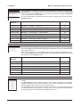
Important Safeguards ................................................................................................................................................................................ 5
Damage Requiring Service ........................................................................................................................................................................ 5
Product Safety ............................................................................................................................................................................................ 6
Electromagnetic Compatibility (EMC) ...................................................................................................................................................... 6
Regulatory Notices ..................................................................................................................................................................................... 6
Manufacturers Declaration of Conformance .......................................................................................................................................... 6
Unpacking ................................................................................................................................................................................................... 6
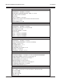
Features, Connections and Setup
Product Description and Features ............................................................................................................................................................... 8
Associated Equipment ................................................................................................................................................................................. 8
Passwords .................................................................................................................................................................................................... 9
Rear Panel Connections .............................................................................................................................................................................. 9
Powering Up ............................................................................................................................................................................................... 13
Minimum Recommended Menu Setup ...................................................................................................................................................... 13
Basic User Operations
The Front Panel .......................................................................................................................................................................................... 15
Live Viewing ................................................................................................................................................................................................ 16
Playback ..................................................................................................................................................................................................... 17
Recording ................................................................................................................................................................................................... 18
Display Options .......................................................................................................................................................................................... 18
Active Cameos ........................................................................................................................................................................................... 19
Sequencing ................................................................................................................................................................................................. 20
On-screen Indicators .................................................................................................................................................................................. 20
Triplex Mode ............................................................................................................................................................................................... 21
The Print Image Feature ............................................................................................................................................................................ 22
The Menu System ...................................................................................................................................................................................... 23
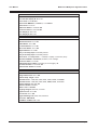
The Main Menu
Time/Date ................................................................................................................................................................................................... 25
Sequencing ................................................................................................................................................................................................. 27
Record ........................................................................................................................................................................................................ 28
Alarms ......................................................................................................................................................................................................... 33
Macro .......................................................................................................................................................................................................... 38
Motion Detection ......................................................................................................................................................................................... 39
Camera Setup ............................................................................................................................................................................................ 41
Archive Setup ............................................................................................................................................................................................. 44
Page 3
MDR Series Multiplexed Digital Recorders
User Manual
CONTENTS
Audio Setup ................................................................................................................................................................................................ 44
Telemetry .................................................................................................................................................................................................... 45
Communications ......................................................................................................................................................................................... 46
Front Panel Lock ........................................................................................................................................................................................ 49
Factory Settings .......................................................................................................................................................................................... 49
Passwords .................................................................................................................................................................................................. 49
The QuickInstall, Operator and SystemView Menus
The QuickInstall Menu ................................................................................................................................................................................ 51
The Operator Menu .................................................................................................................................................................................... 51
The SystemView Menu ............................................................................................................................................................................... 51
Alarms
Alarm Input ................................................................................................................................................................................................. 56
Alarm Output .............................................................................................................................................................................................. 56
Alarm Acknowledge .................................................................................................................................................................................... 56
On-Screen Displays During Alarms ........................................................................................................................................................... 56
Alarm Operations During Playback ............................................................................................................................................................ 57
Alarm History Box ....................................................................................................................................................................................... 57
Searching
Disk Analysis Screen .................................................................................................................................................................................. 59
Quick Archive to CD ................................................................................................................................................................................... 59
Motion Search ............................................................................................................................................................................................ 59
Search Filters ............................................................................................................................................................................................. 60
Search Results ........................................................................................................................................................................................... 61
WaveBrowser and WaveLink
WaveBrowser ............................................................................................................................................................................................. 63
WaveBrowser Layout and Controls ............................................................................................................................................................ 64
WaveLink .................................................................................................................................................................................................... 65
Technical Specifications and RS232 Protocols
Technical Specifications ............................................................................................................................................................................. 67
RS232 Alarm/Event Generation and Text Insertion Protocol ..................................................................................................................... 68
RS232 Remote Control Protocol ................................................................................................................................................................ 70
Appendix: External Archiving Devices .................................................................................................................................................. 73
Page 4
User Manual
MDR Series Multiplexer Digital Recorders
IMPORTANT SAFEGUARDS
This product is exclusively for use in CCTV applications and has no other purpose.
Read and Retain these Instructions - All the safety and operating instructions must be read before the unit is operated
and should be retained for future reference.
Cleaning - Unplug the unit from the supply outlet before cleaning. Use a damp cloth for cleaning. Do not use liquid or
aerosol cleaners.
Accessories - Do not use accessories that have not been recommended by the product manufacturer as they may cause
hazards.
Water and Moisture - Do not install this unit near sources of water. For example, near a bathtub, wash bowl, kitchen sink, or
laundry tub, in a wet basement, near a swimming pool, in an unprotected outdoor installation, or any area that is classified as a
wet location. Do not expose the unit to rain or moisture. Moisture can damage internal components.
Mounting During Installation - Do not place this unit on an unstable stand, tripod, bracket, or mount. The unit may fall,
causing serious injury to a person and serious damage to the unit. Any mounting of the unit should follow the manufacturers
instructions, and should use a mounting accessory kit supplied by the manufacturer.
Chassis: Other equipment may be placed on top of the unit if it weighs less than 35 pounds (16 kilograms).
Temperature: Observe the units operating temperature (0 to 40OC) and non-condensing humidity specifications (10% to
80%) when choosing a location for the unit. Extremes of heat or cold beyond the specified operating temperature limits
may cause the unit to fail. Do not install this unit on top of other hot equipment.
Ventilation - Install the unit in a well-ventilated area. Openings in the enclosure are provided for ventilation to ensure
reliable operation of the unit and to protect it from overheating. These openings must not be blocked or covered, and
therefore this unit should not be placed in a built-in installation unless proper ventilation is provided. Do not place directly
on other hot equipment, because this may increase its operating temperature.
Power - Ensure that the sites AC power is stable and within the rated voltage of the 12V DC power supply. If the sites AC
power is likely to have spikes or power dips, use power line conditioning or an Uninterruptable Power Supply (UPS).
Power-Cord Protection - Power-supply cords should be routed so that they are not likely to be walked on or pinched by items
placed upon or against them, paying particular attention to cords at plugs, and the point where they exit from the appliance.
Cable Runs - cabling of the unit must be in accordance with the country of installations national wiring regulations.
Object and Liquid Entry - This equipment must be protected from the ingress of foreign materials. Never push objects of
any kind into this unit through openings as they may touch dangerous voltage points or short-out parts that could result in
a fire or electric shock. Never spill liquid of any kind on the unit.
Servicing - There are no user-serviceable parts. Do not remove the covers as this may expose you to dangerous voltages
or other hazards. Refer all servicing to qualified service personnel.
Replacement Parts - When replacement parts are required, an approved service agent must be used in order to ensure
any replacement parts used meet the specifications of the manufacturer. The use of unauthorised substitute components
may result in fire, electric shock or other hazards.
Safety Check - Upon completion of any service or repairs to this unit, suitably qualified personnel must perform all relevant
safety checks to determine that the unit is in a proper and safe operating condition e.g. flash testing, PAT testing, etc.
Signal Cables Connected to 0V (signal ground) - Ensure connections to signal cable 0V are made in accordance with
the country of installations national wiring regulations to ensure safe operation and to minimise earth loops. This must not
be confused with the safety earth connection required for Class 1 equipment, i.e., equipment that must be connected to a
safety earth for safe operation.
Non-Use for Long Periods - If the unit is not to be used for long periods, it is recommended that input power, and all
interface cables are disconnected from the unit.
DAMAGE REQUIRING SERVICE
Unplug the unit from the outlet and refer servicing to qualified service personnel under the following conditions:
When the power supply cord or plug is damaged.
If liquid has been spilled, or objects have fallen into the unit.
If the unit has been exposed to rain or water.
If the unit does not operate normally by following the operating instructions.
If the unit has been dropped or the cabinet has been damaged.
When the unit exhibits a distinct change in performance.
If the unit has no power even when the power supply appears to operate correctly. If this is the case then ask a service
engineer to test the internal fuse.
Page 5
MDR Series Multiplexed Digital Recorders
User Manual
PRODUCT SAFETY
Installation is only to be carried out by competent, qualified and experienced personnel in accordance with the
country of installations National Wiring Regulations.
The unit contains no user-serviceable parts.
This unit contains a lithium battery whose expected life is in excess of five years. If the unit loses its settings
each time it is switched off then the battery needs replacing. In this instance return the unit to the manufacturer
or manufacturers approved service agent who will replace the battery.
There is a danger of explosion if the lithium battery is incorrectly replaced. Replace only with the same or an
equivalent type recommended by the manufacturer. Dispose of unused batteries according to the manufacturers
instructions.
The unit must not be used in a medical and/or intrinsically safe application and is intended for general purpose
CCTV applications only.
Do not exceed the voltage and temperature limits given in the specification. Only operate the unit in a clean, dry,
dust-free environment, pollution degree 2, overvoltage 2. Altitude not to exceed 2000m above sea level.
ELECTROMAGNETIC COMPATIBILITY (EMC)
This is a Class A product. In a domestic environment this product may cause radio interference in which case the
user may be required to take adequate measures.
Radio Frequency Emissions
British standard BSEN50081-2:1994 Electromagnetic compatibility - Generic emission standard. Part 2. Industrial
environment.
British standard BSEN55022:1998 Limits and methods of measurement of radio disturbance characteristics of information
technology equipment.
Immunity
British Standard BSEN 50130-4:1996 Alarm Systems Part 4 Electromagnetic compatibility.
Product family standard: Immunity requirements for components of fire, intruder and social alarm systems.
REGULATORY NOTICES
This equipment has been tested and found to comply with the limits for a Class A digital device, pursuant to part 15 of the
FCC Rules. These limits are designed to provide reasonable protection against harmful interference when the equipment
is operated in a commercial environment. This equipment generates, uses, and can radiate radio frequency energy and, if
not installed and used in accordance with the instruction manual, may cause harmful interference to radio communications.
Operation of this equipment in a residential area is likely to cause harmful interference in which case the user will be
required to correct the interference at his own expense.
Modifications not expressly approved by the manufacturer could void the users authority to operated the equipment under
FCC rules.
MANUFACTURERS DECLARATION OF CONFORMANCE
A Declaration of Conformity in accordance with the above EU standards has been made and is on file at Baxall Limited,
Stockport, SK6 2SU, England.
The manufacturer declares that the product supplied with this document is complaint with the provisions of the EMC
Directive 89/336 EEC, the Low Voltage Directive LVD 73/23 EEC, the CE Marking Directive 93/68 EEC and all associated
amendments.
UNPACKING
Check the package and contents for visible damage. If any components are missing or damaged, contact the supplier
immediately. Do not attempt to use the unit. If, for any reason they must be returned, the contents must be shipped in the
original packaging.
The MDR unit
This User Manual
Alarm Interface Circuit Board
WaveReader Software and Manual
Audio Cable
Quick Reference Guide
Power Supply
Power Cords (120V AC and 220V AC)
Page 6
User Manual
MDR Series Multiplexer Digital Recorders
FEATURES, CONNECTIONS
AND SETUP
Page 7
MDR Series Multiplexed Digital Recorders
User Manual
PRODUCT DESCRIPTION AND FEATURES
An MDR Series Multiplexed Digital Recorder is a video multiplexer capable of recording from multiple cameras to an
internal hard drive while simultaneously providing playback. Unlike outdated timelapse VCRs, the MDR records highresolution pictures. Digital recording improves playback quality over VCRs, and eliminates the hassle of cleaning heads,
changing tapes or servicing motors. The unit can also be programmed to record continuously by overwriting the oldest
recorded data. Depending on the setup, the MDR can store from a few hours to more than three years of colour images.
Programmable search features eliminate time consuming fast-forwarding or rewinding of tapes, searching for critical data.
Searches for recorded images or events can be filtered by alarm, time, date, motion, video loss, camera number and ASCII
cash register or ATM text.
Features of the MDR include:
Multiplexer functionality with built-in digital recording
Triplex simultaneous recording, playback, and live multiscreen viewing
Remote programming and control through the RS232, RS485 and Ethernet ports
View live or recorded images remotely using WaveReader software
Dual multiscreen monitor displays
Auto-detect video mode on startup (PAL or NTSC)
Video motion detection (intrusion and activity)
Motion search
Preview search results with thumbnail images
Record speed selectable per camera
Displays include full screen, sequenced, picture-in-picture, and multiscreens
Alarm Handling with history log. Pre and post alarm recording, selectable per camera
Archive onto Baxall MDAe Disk Array, RAID, DAT, AIT, or CD-Rs
IEEE 1394 Firewire interface for Baxall MDAe Disk Array or Firewire Disk Drives
Continuous recording with simultaneous archiving
PTZ control via ethernet or POTS, using compatible keyboards
Covert camera recording (recording without display)
Auto-daylight savings time change function
Clock synchronization with network server
Alarm notification via email and/or TCP/IP
Integrated WaveBrowser software
Dynamic IP addressing (DHCP)
One-touch image printing directly from the MDR
This products primary purpose is to furnish video multiplexing and recording. Although the unit has alarm handling and
motion detection functions, they are considered secondary features. This unit should not be the only alarm device on
site.
Products covered by this handbook
MDR+CT16M4/0GB
MDR+CT16M4/640GB
MDR+CT16M4/320GB
MDR+CT16M4/1TB
ASSOCIATED EQUIPMENT
Associated equipment in a typical security system could contain the following items:
Five monitors
A compatible keyboard
Video cameras: composite video, 1 volt peak-to-peak
Alarm input devices: pressure sensors, motion detectors, etc
Alarm output devices: buzzers, sirens, flashing lights, etc
A PC connected via Ethernet cable
An external archive device, such as a MDAe, RAID, CD-R, DAT, or AIT drive
Printer with printer server connected via Ethernet cable
For instructions regarding the connection of the associated equipment, consult the instruction manual of the associated
equipment.
Page 8
User Manual
MDR Series Multiplexer Digital Recorders
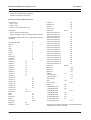
PASSWORDS
Passwords are provided to limit access to menus and certain features. Two levels of password security are provided:
Operator: Limited menu access, only Operator and SystemView menus are available.
Installer: Complete menu access.
It is recommended that the default passwords are changed after installation is complete. As a security measure, store the
password in the administrators secured files or in a limited access area.
Password
Type
Access
Level
Function
Changeable
by user?
Default
Password
Operator
Operator
Provides access to the Operator
and System View menus
Yes
Press ENTER
3 Times]
Installer
Installer
Provides access to all on-screen menus
Yes
347
Language
Installer
Provides access to the Onscreen
Language menu
No
123
Factory
Defaults
Installer
Resets the multiplexer to factory defaults
No
811
Ethernet
Access
Installer
Deactivates the ethernet password, so that the unit may
be accessed by any PC equipped with WaveReader
No
111
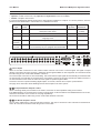
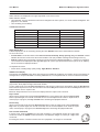
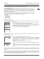
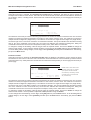
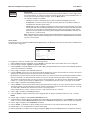
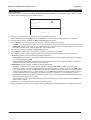
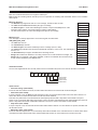
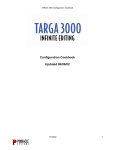
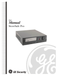
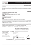
REAR PANEL CONNECTIONS
1
2
4
3
5
6
AUX
7
8
RS485/1
ETHERNET
10/100
12 VDC
2
3
4
5
6
7
8
9
10
11
12
13
14
15
S-VHS
1
16
SCSI
B
IEEE 1394
RS232
B
9
10
11
12
13
RS485/2
RS232
14
15
Camera Inputs
There are two BNC connectors for each camera. Either connector can receive a camera signal. The signal is looped
(directly connected to the other connector), making the camera signal available to other equipment. All connections should
be made using 75-ohm coxial cable with BNC connectors.
The camera input connectors are auto-terminating. This means that the input signal will automatically be terminated with
75-ohms unless a second cable is connected to the second BNC connector of the same camera input. Make sure there is
75-ohm termination at the end of the video line if the signal is looped through the MDR.
Time base correction is performed during digital capture. As a result, cameras do not require synchronization.
See page 42 for information about disabling unused camera inputs in the menu system.
,
Composite Monitor Outputs A and B
When connecting directly from the MDR to the monitor, select the 75-ohm impedance setting on the monitor.
If an additional device is connected to the monitors looping output, set the termination of the additional device as 75-ohm,
and set the termination of the monitor as Hi-Z (High impedance).
All connections should be made using 75-ohm coxial cable with BNC connectors.
,
Y/C Monitor Outputs A and B
The Y/C video outputs have a 4-pin mini-DIN style connector. This style of connection is also referred to as SVHS and SVideo. All connections should be made using 75-ohm coxial cable.
Page 9
MDR Series Multiplexed Digital Recorders
User Manual
REAR PANEL CONNECTIONS
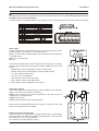
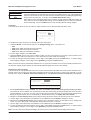
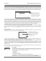
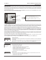
Alarm I/O Port
The back panel of the unit is equipped with an alarm I/O port (DB-25 style connector). Do not attempt to wire directly to
the DB-25 connector on the back panel.
Connect the alarm PCB (supplied with the unit) to the alarm I/O port. Wire all alarm inputs to the alarm PCB as show below:
Alarm Inputs
An alarm condition can be activated by devices such as pressure pads, passive
infrared detectors, door switches, or other similar devices.
Alarm Alarm
Input Inputs
1
2-15
Input: 1 per video channel, programmable in the menu system as normally-open
or normally-closed.
Pin
1
Pins
2-15
Alarm
Input
GND
16
Pin
16
Pins
18-20
High: +5V (+12V maximum)
Low: 0V
Once connected, alarm inputs can be configured as normally-open or normallyclosed using the menu system. Alarms types should be configured in the menu as
follows:
Normally-Open, Zero Potential Relay Contact: Normally-Open
Normally-Closed, Zero Potential Relay Contact: Normally-Closed
TTL Active High: Normally-Closed
TTL Active Low: Normally-Open
Open Collector Active On: Normally-Open
Open Collector Active Off: Normally-Closed
For more details on alarm configuration, see page 33.
Alarm Relay Outputs
Alarm relay outputs can be activated when an alarm condition exists. The alarm
output is only active for the duration of the alarm.
Output: Zero potential relay contacts programmable in the menu system as
normally-open or normally-closed.
Voltage: 30V maximum
Current: 500mA maximum (short circuit protected)
Pin
17
Alarm relays can be programmed in the menu system to respond to macros and
video loss. See page 36 for more details.
External Alarm Acknowledge Input
Connect to a switch or similar device to ground this pin in order to acknowledge
an alarm condition, and silence associated buzzers and relays. Connect from pin
23 to either pin 18, 19, or 20 (ground pins).
The contact is a normally-open relay contact.
Page 10
Pin
21
Pin
22
Pin
25
User Manual
MDR Series Multiplexer Digital Recorders
REAR PANEL CONNECTIONS
Power Input
This 2.1mm barrel, centre positive connector is to be connected to the supplied power supply unit. The unit runs on a 12V
DC, 60 Watt (5 Amp) power supply.
Aux Port
The back panel of the unit is equipped with a aux port (DB-9 style connector). Do not attempt to wire
directly to the DB-9 connector on the back panel.
Connect the supplied audio cable to the aux port. The cable provides five labelled connectors for the
audio input and output, and BNC connectors for monitors C, D, and E:
Audio Output: RCA connector
Audio Input: RCA connector
Composite Monitor C Output: Composite video output with BNC style connector
Composite Monitor D Output: Composite video output with BNC style connector
Composite Monitor E Output: Composite video output with BNC style connector
,
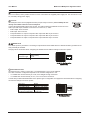
RS485 Ports
Two RS485 ports are provided for connecting to keyboards and other RS485 devices. Shields should be grounded at one
end, preferably at the MDR.
See page 48 for information about configuring the RS485 network address settings in the menu system.
Wire Type
24 AWG, Twisted Pair with
shield (2-wire)
Connector Type
RJ-45
Max Cable Length 3200 feet / 1000 metres
Pin
1
2
3
4
5
6
7
8
Use
Ground (Shield)
Not connected
Network +VE
Not connected
Not connected
Network -VE
Not connected
Not connected
1 2 3 4 5 6 7 8
10/100 Ethernet Port
The Ethernet port is used to connect live or recorded images to a PC via the Ethernet.
The cable connection configuration depends on the network configuration in use:
For a MDR that connects directly to a hub, use a Straight Through connection.
For a MDR that connects directly to a PC, use a Cross Over connection.
Consult with your Network Administrator for the specific type of configuration. See page 48 for information about configuring
the ethernet settings in the menu system.
Wire Type
Connector Type
Max Cable Length
Minimum Cable Length
Hub Wiring Configuration
PC Wiring Configuration
Cat 5
RJ-45
328 feet / 100 metres
6 feet / 1.8 metres
Straight Through
Cross Over
Pin
1
2
3
4
5
6
7
8
Use
TX+
TXRX+
Not connected
Not connected
RXNot connected
Not connected
1 2 3 4 5 6 7 8
Page 11
MDR Series Multiplexed Digital Recorders
User Manual
REAR PANEL CONNECTIONS
SCSI Port
The unit is equipped with a SCSI port for connecting external archive devices. The unit only supports a single SCSI device.
The SCSI ID of the archive device must be set to 0 and the SCSI bus must be terminated, otherwise the system will not
operate correctly.
Additional menu setup may be necessary to configure the archive device. See page 44 for more details.
Connector
Gender (on unit)
Compatible devices
SCSI ID
50 Pin, High Density SCSI-2
Female
MDAe, RAID, DAT, AIT, CD-R, CD-RW
0
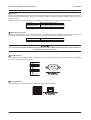
IEEE 1394 Firewire Port
The unit is equipped with an IEEE 1394 Firewire port for connecting Firewire compatible external archive devices. For
information on the approved devices, please refer to the Archiving Addendum at the back of this manual.
Connector
Cable
6 position DIP
6 position Firewire
Do not connect both SCSI and IEEE 1394 archiving devices to the MDR. Archiving support is only available for
one type of interface at any one time.
DB-9 RS232 Port
A DB-9 RS232 port is provided for modem connection or remote control of unit. See page 47 for information about configuring
the modem settings in the menu system.
Pin
1
2
3
4
5
6
7
8
9
Function
DCD
RX
TX
DTR
Ground
Not connected
RTS
CTS
Not connected
1
5
6
9
RJ-45 RS232 Port
A RJ-45 RS232 port is provided for Event Generation and ASCII Text insertion.
Pin
1
2
3
4
5
6
7
8
Page 12
Use
Ground
Reserved
Not connected
RXD
TXD
Not connected
Ground
Reserved
1 2 3 4 5 6 7 8
User Manual
MDR Series Multiplexer Digital Recorders
POWERING UP
It is important that power-up procedures are followed carefully. The unit uses an auto-detect feature to detect camera
signals during power-up, and configures itself automatically.
Power-Up Procedure
Before applying input power to the unit, ensure that all the required connection cables are securely connected. Apply power
to all monitors and cameras, and then apply power to the MDR unit.
Once power is applied to the unit, it will begin the power-up procedure. The unit will begin by displaying the software version
on Monitor A and then the unit will begin recording automatically.
Check Video Input Quality
Check the picture quality by selecting each camera for full screen display. If the picture quality is poor, check the following
items:
The BNC connections
The loop-through terminations
The video levels of incoming signals
The possibility of ground loops
Consult the cameras installation instructions for additional information about proper camera setup.
Check Record And Playback Quality
Record for at least three minutes at the default record rate. Then playback the recording, selecting each camera for full
screen display. Check the playback picture quality.
MINIMUM RECOMMENDED MENU SETUP
After installation is complete, it is strongly recommended that, as a minimum, the items in the QuickInstall menu are
configured before the unit is used. All the features located in the QuickInstall menu are also found in the Main menu.
These items are provided in the separate QuickInstall menu as a convenience for the installer.
For information about accessing and configuring the menu system, see page 23.
To find detailed information in this manual about configuring each item in the QuickInstall menu, use the following table to
locate the Main menu location of each item in the QuickInstall menu.
QuickInstall
Menu Item
Main Menu Location
Page In Manual
Change the Time
Main Menu ® Time/Date ® Set Time
25
Change the Date
Main Menu ® Time/Date ® Set Date
25
Edit Camera Titles Main Menu ® Camera Setup ® Camera Titles ® Edit Titles
42
Camera Disable
Main Menu ® Camera Setup ® Camera Disable
42
Telemetry Enable
Main Menu ® Telemetry ® Telemetry Enable
45
Record Quality
Main Menu ® Record ® Record Quality
29
Installer Password Main Menu ® Passwords ® Installer Password
49
Auto Disable Now
42
Main Menu ® Camera Setup ® Camera Disable ® Auto Disable Now
Page 13
MDR Series Multiplexed Digital Recorders
BASIC USER OPERATIONS
Page 14
User Manual
User Manual
MDR Series Multiplexer Digital Recorders
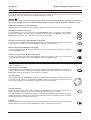
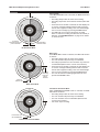
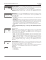
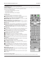
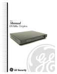
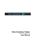
THE FRONT PANEL
1
2
A
3
4
C
D
5
E
B
11
{F}
6
1
2
3
4
5
6
7
8
9
10
11
12
13
14
15
16
12 13 14 15
7
8
16 17 18
9
10
19
Multiscreen Selection Buttons: Select 16, 10, 7, and 4 way multiscreen displays.
Monitor Selection Buttons: Select Monitor A or Monitor B.
Multiscreen Selection Buttons: Select 13, 9, 6 way, and picture-in-picture multiscreen displays.
Monitor Selection Buttons: Select Monitors C, D, or E.
Number Buttons: Select Cameras 1 through 16.
Reverse Play Button: Begin playback in reverse.
Freeze Button: Freeze camera images on-screen in Live mode. Pause playback.
Play Forward Button: Begin playback.
Jog/Shuttle: Controls playback speed and menu selections. The Jog is the inner dial and the Shuttle is the outer dial.
Menu Button: Provides access to on-screen menus.
Power Indicator: Indicates power on/off condition.
Alarm button: Acknowledge and silence alarms.
Sequence Button: Sequence camera views.
Zoom Button: Provides a X2 digital zoom.
Function Button: Used in conjunction with the Number buttons to run macros.
Record Button: Start and stop recording.
Stop Button: Stop playback and return to Live mode.
Search Button: Access to stored video data.
Enter Button: Confirm selections in menus.
Important Note: If telemetry is enabled via a remote keyboard, the front panel controls on the MDR are disabled. To reestablish front panel control, ensure that telemetry is switched off at the remote keyboard.
Page 15
MDR Series Multiplexed Digital Recorders
User Manual
LIVE VIEWING
The MDR has three principal modes of operationLive Viewing, Playback and Recording. All three of these modes can
operate simultaneously. In Live mode, the following operations are available:
Full Screen Display
Select any camera for full screen display by pressing the Number button of the desired camera. Pressing
the same Number button again displays the Status Display Box. Pressing the same button a third time
displays any associated ATM or cash register ASCII text.
1
Multiscreen Display
In Live Multiscreen mode, press one of the Multiscreen buttons to activate the multiscreen display on the
currently selected monitor (Monitor A or Monitor B). Live multiscreens are displayed with grey borders. For
detailed information about multiscreen displays, see page 18.
Multiscreen Display With Sequencing
If a multiscreen display does not include all of the cameras, the remaining cameras can be sequenced in
the bottom right cameo. While in a multiscreen display, press the Sequence button to begin sequencing.
For detailed information about sequencing, see page 20.
Sequenced Full Screen Display
While in a full screen display, press the Sequence button to begin full screen sequencing.
The sequence list and dwell times are programmable. For detailed information about programming the
sequence list see page 20.
Zooming
To activate the X2 digital zoom, select the full screen display of the camera that is to zoom, then press the
Zoom button. Zooming will be indicated by the LED located directly above the Zoom button. Zooming is
also indicated as ZOOM on the primary monitor. Zooming works with frozen and non-frozen images.
Zoomed images can also be frozen. While zoomed, rotate the Jog/Shuttle to pan and tilt across the
image. Please note, the camera does not move during digital pan/tilt.
Press the Zoom button again, or another camera button to cancel the zoom operations.
Note: If the Zoom button is pressed while in a multiscreen display, the camera from the last active cameo
is selected for full screen display. Press the Zoom button again to activate the zoom operation.
Freezing
Pressing the Freeze button freezes all camera images on-screen. Full screen freezing is indicated as FRZ
on-screen. Multiscreen freezing is indicated as a flashing asterisk in each frozen cameo. Individual cameos
can be frozen in Active Cameo mode (see page 19). Press the Freeze button again or any Number button
to cancel freeze operations.
Selecting Monitor B
To control Monitor B, press the Monitor B button. The Monitor B LED will light to indicate that the number
keypad now controls Monitor B.
Press the Monitor A button again to return the keypad control to Monitor A.
Selecting Monitors C, D and E
To control Monitors C, D or E, press the corresponding Monitor button. The Monitor LED will light to
indicate that the Monitor has been selected.
A
B
C
D
E
Page 16
User Manual
MDR Series Multiplexer Digital Recorders
PLAYBACK
Playback is always displayed on Monitor A. Playback multiscreen borders are black, as opposed to the grey borders of the
live multiscreens. When in Playback mode, Monitor B continues to display full or multiscreen live images.
To begin playback, press the Play Forward or Reverse Play button.
Play Forward
When the Play Forward button is pressed, the unit will play forward at the rate the data was recorded.
While in Playback mode, the user may change the playback direction, playback speed, etc. To return to
Play Forward operations, press the Play Forward button.
Reverse Play
To begin reverse playback, press the Reverse Play button.
Fast Forward and Rewind
During playback, rotate the Shuttle (the outer dial) clockwise to view data at a higher than normal rate.
Rotate the Shuttle anti-clockwise to view data in reverse at a higher than normal rate.
Increasing the amount of rotation increases the rate of playback.
Auto Pause
During playback, moving the Jog (the inner dial) in any direction will freeze playback. Depress the Freeze,
Play Forward or Reverse Play buttons to continue playback.
Freeze
During playback, press the Freeze button. This feature pauses all full screen and multiscreen images
Single Frame Advance & Single Frame Rewind
Whilst in Freeze or Pause mode, rotate the Jog (the inner dial) to view the frame directly before or after the
frame currently displayed on-screen.
Stop Playback
To stop playback and return to Live Multiscreen mode on Monitor A, press the Stop button.
Multiscreen Display
During playback, press one of the Multiscreen buttons to activate a multiscreen display. The 6-way and
PIP multiscreen displays are not available in Playback mode.
For detailed information about multiscreen displays, see page 18.
Multiscreen Display With Sequencing
If a multiscreen display does not include all of the cameras, the remaining cameras can be sequenced in
the bottom right cameo. While in a multiscreen display, press the Sequence button to begin sequencing.
For detailed information about sequencing, see page 20.
Full Screen Display
Select any camera for full screen display by pressing the Number button of the desired camera. Pressing
the Number button again displays the Status Display Box. Pressing the same button a third time displays
any associated ATM or cash register ASCII text.
1
Zooming
To activate the X2 digital zoom, select the full screen display of the camera that is to zoom, then press the
Zoom button. Zooming will be indicated by the LED located directly above the Zoom button. Zooming is
also indicated as ZOOM on the monitor. Zooming works with frozen and non-frozen images. Zoomed
images can also be frozen. While zoomed, rotate the Jog/Shuttle to pan and tilt across the image. Please
note, the camera does not move during digital pan/tilt.
Press the Zoom button again, or another camera button to cancel the Zoom operations.
Note: If the Zoom button is pressed while in a multiscreen display, the camera from the last active cameo
is selected for full screen display. Press the Zoom button again to activate the zoom operation.
Page 17
MDR Series Multiplexed Digital Recorders
User Manual
PLAYBACK
Searching Recorded Data
The MDR has a powerful search interface feature that allows the user to search for data on the internal hard disk or an
external archive device. The user may search the data for previous recording sessions, text insertion, alarm conditions or
for motion in a selectable area of the scene. Because the search interface is so dynamic, the search interface is covered in
detail in a separate section of this manual. See page 58 for more details.
RECORDING
To begin recording, press the Record button. Recording will be indicated by the LED located directly
above the Record button. The unit always starts recording at the end of previously recorded data. The unit
will continue recording until the Record button is pressed again.
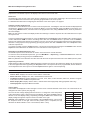
Monitor Displays During Recording
Multiscreen Live and Playback displays on Monitor A and Monitor B are not affected by recording operations.
MONITOR A
MONITOR B
LIVE
LIVE
PLAY
BACK
LIVE
OR
PLAY
BACK
OR
MONITOR C, D, E
LIVE
LIVE
LIVE
LIVE
LIVE
LIVE
LIVE
DISPLAY OPTIONS
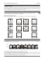
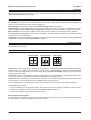
Available Multiscreen Displays
Use the Multiscreen buttons to activate the multiscreen display on Monitor A or Monitor B. Pressing an individual Multiscreen
button will display the corresponding multiscreen.
Button
Display
4-Way
6-Way
7-Way
9-Way
10-Way
13-Way
16-Way
PIP
The multiscreen display is limited to the number of camera inputs on the unit.
The camera assignments for each multiscreen is retained (in non-volatile memory) for both Live and Playback multiscreen
mode on Monitor A, as well as Live multiscreen mode on Monitors B, C, D and E.
PIP: Use the Jog/Shuttle to adjust the location and size of the PIP display. Please note that the PIP display is only available
on Monitor A in Live mode when Monitor B is in full screen display mode.
Page 18
User Manual
MDR Series Multiplexer Digital Recorders
DISPLAY OPTIONS
Displays on Monitors C through E
These are full screen and analog monitors, displaying only Live images (regardless of the mode selected). A sequenced or
fixed display of any one camera can be selected on Monitors C through E.
The time, date, alarm, video loss messages, titles and all on screen data on Monitors C through E are related to
current, live data and must not be confused with the playback data that might be displayed on Monitors A or B.
Independent Sequence List and Dwell Times
Independent full screen sequences may operate on Monitors A through E. See page 20 for more details.
Operating on Monitors C through E
To control Monitors C, D or E, press the corresponding Monitor button. The Monitor LED will light to
indicate that the Monitor has been selected. While the LED remains on, the Number buttons and the
Sequence button operate on the selected monitor, and not on Monitor A.
C
D
E
Selecting a Camera Full Screen on Monitors A through E
To select a full screen display of an individual camera, select the required monitor (the LED for the selected
monitor will come on) and then press the Number button for the required camera.
1
Starting Sequencing on Monitors A through E
To select a sequence, select the required monitor (the LED for the selected monitor will come on) and then
press the Sequence button.
Cancelling Sequencing on Monitors A through E
To cancel a sequence, select the monitor which the sequence is running on (the LED for the selected
monitor will come on) and then press the Sequence button or a Number button.
ACTIVE CAMEOS
A cameo is defined as any cell within a multiscreen display. Active Cameo mode allows the user to access and edit each
cameo individually.
Entering Active Cameo Mode
While viewing a multiscreen display, enter Active Cameo mode by pressing the Enter button. Active Cameo
mode is indicated on-screen by flashing the number and titles of the active cameo. The LED above the
Enter button is also lit. By default, the top left cameo is activated.
Selecting Cameos
Select a cameo using the Jog/Shuttle to navigate around the multiscreen display. Rotating the Jog selects
the next screen up or down a row. Rotating the Shuttle selects the next screen in numerical order. The
active cameo will always be indicated by the flashing camera number and titles.
Selecting Cameras
Display any camera in the active cameo by pressing the Number button of the desired camera. Once a
camera has been selected, the active cameo advances to the next cameo on the right.
1
The camera selection only changes the multiscreen currently being displayed. Each multiscreen must be
configured separately. Changes to the multiscreen display are saved in non-volatile memory, and will be
retained even if power is removed from the unit.
Freezing
Press the Freeze button to freeze the image in the selected cameo. Each frozen cameo is indicated as a
flashing asterisk on-screen. Press the Freeze button again to cancel freeze operations.
Page 19
MDR Series Multiplexed Digital Recorders
User Manual
SEQUENCING
The sequencing feature allows a camera to be displayed briefly on-screen, before advancing to the next camera in the
sequence list. The default sequence list displays each camera in numerical order.
Dwell Time
The dwell time is the amount of time each camera is displayed on-screen before advancing to the next camera. The Full
Screen and Multiscreen Dwell Times are separately programmable in the menu system.
For detailed information about configuring the dwell times in the menu system, see page 27.
Autolist Custom Sequence List
The Autolist feature allows the user to create a custom sequence list, controlling the order the cameras are displayed and
the dwell time. Separate Autolists may be created for Monitor A (Live and Playback mode) and Monitor B through E (Live
mode). Using a Monitor button, select the monitor to be programmed. Then, using a Number button, select any camera for
full screen display.
Note: The unit must be in full screen display mode before starting to create the sequence list. This initial camera is not part
the sequence list.
To begin recording the Autolist sequence, press the Alarm button and Sequence button simultaneously. Autolist Program
mode is indicated as PGM on-screen. Recording starts when the first Number button is pressed. Press the Number
buttons in the order that the cameras are to appear on-screen. The amount of time between button presses determines the
dwell time. During sequence list programming, pressing any button other than a Number button or the Sequence button
voids the sequence list.
To end the recording, press the Sequence button. The amount of time between pressing the last Number button and the
Sequence button determines the dwell time for the final camera in the sequence list.
Returning To The Default Sequence List
The default sequence list is all cameras in numeric order with a three second dwell time.
To return the unit to the default sequence list, go to the Main Menu ® Sequencing ® Fullscreen Dwell menu. Select 03
seconds by rotating the Jog, then press the Enter button.
Note: Any alteration of the dwell time from this menu will cancel the sequence list and return to the default (numeric) order.
Sequencing In Cameos
While viewing a multiscreen display, additional cameras (cameras not shown in the multiscreen display) can be sequenced
in the lower right hand cameo by pressing the Sequence button. The sequence list is not programmable, but the dwell time
can be adjusted in the menu system. Press the Sequence button again to cancel sequencing.
ON-SCREEN INDICATORS
There are five types of on-screen indicators.
Camera Titles: Displays the camera number and the camera title.
Status Indicators: Displays time, date, and hard disk record time left.
Conditional Indicators: Displays indicators for freeze, zoom, alarm, motion detection, video loss, Autolist Program
mode, Macro Record and Macro Playback mode.
Status Display Box: Displays archive device, network status and image quality setting (Playback mode only).
Text Display Box: Displays ATM/POS text data.
Camera Titles
Camera titles are displayed on either the upper or lower corner of the left hand side of the screen. The camera title can be
changed in the menu system (see page 42).
The user can also change display position and colour. To change the colour and position
of the camera titles, select a camera for full screen display, then press the Enter button to
advance to the next display setting. Repeatedly pressing the Enter button advances the
display settings through the sequence show in the table on the right.
Example: Select Camera 1 for full screen display. Using the Enter button, cycle through
the sequence shown on the right. Each time the position cycle is completed, the unit
advances the Status Indicator colour. Choose Black, White or Grey.
Position
Colour
Top Left
Black
Top Left
White
Top Left
Grey
Bottom Left
Black
Bottom Left
White
Bottom Left
Grey
Title not displayed
Page 20
User Manual
MDR Series Multiplexer Digital Recorders
ON-SCREEN INDICATORS
Status Indicators
Status indicators are displayed in the upper right hand corner of the screen.
Status indicators include:
Time and Date. The Time and Date format can be changed in the menu system, or it can be turned off altogether. See
page 25 for more details.
Time remaining on hard disk(s).
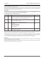
Conditional Indicators
Condition
Full Screen Indicator
Multiscreen Indicator
A in cameo of camera in alarm
Alarm
ALM
Autolist Program mode
PGM
PGM
Freeze
FRZ
Asterisk in frozen cameo
Macro Record mode
Motion Detection
Videoloss
Zoom
F followed by Macro Number
F followed by Macro Number
M
M in cameo with motion detection
VDL
V in cameo with videoloss
ZOOM
ZOOM
Status Display Box
A Status Display Box can be viewed by pressing the same Number button twice. Status indicators include:
On a Live full screen:
Archive Status: The archive status can be Not Connected, Not Ready, Ready, Ejecting, Play, and timeleft. Timeleft
indicates the amount of time before the archive medium is full (only available if background archiving turned on).
Network: Displays all current network connections. Normal connection is displayed as ip.ip or - if there is no connection.
Live connections are displayed as E1: ip.ip, E2: ip.ip, etc. (where ip.ip represents the last 2 bytes of the IP address).
POTS connection is displayed as IP 1.1.
On Playback full screen:
All the above, including image quality setting: High, Medium, Standard.
ATM/POS Text Display
Pressing the same Number button three times brings up an ATM/POS text display. This feature can be used during Live
viewing mode to verify that the MDR is receiving ATM/POS text, or in Playback mode to review recorded text and video.
TRIPLEX MODE
Triplex mode allows the display of both live and playback images to appear on Monitor A simultaneously. Live images have
grey borders, while playback images have black borders.
To enter Triplex mode, press the Play Forward button while in Play Forward mode. Alternatively, press the Play Reverse
button while in Play Reverse mode. The LED above the relevant Play button and the LED above the Stop button turn on to
indicate that the unit is in Triplex mode.
Monitor B always switches to a full screen live display whenever Triplex mode is entered.
Play Forward
When in Play Forward mode, press the Play Forward button to enter Triplex mode. When the Play Forward
button is pressed again, the unit will revert back into the normal Playback mode. While in Triplex mode, if
reverse play is in progress, the Play Forward button will change the playback direction.
Reverse Play
When in Reverse Play mode, press the Reverse Play button to enter the Triplex mode. When the Reverse
Play button is pressed again, the unit will revert back into the normal Playback mode. While in Triplex
mode, if forward play is in progress, the Reverse Play button will change the playback direction.
Fast Forward and Rewind
In Triplex mode, rotate the Shuttle (the outer dial) clockwise to view playback images at a higher than
normal rate. Rotate the Shuttle counter-clockwise to view playback images (in reverse) at a higher than
normal rate
Increasing the amount of rotation increases the rate of playback. Live images are not affected.
Page 21
MDR Series Multiplexed Digital Recorders
User Manual
TRIPLEX MODE
Freeze
In Triplex mode, press the Freeze button to pause all multiscreen images, both Live and Playback.
Single Frame Advance & Single Frame Rewind
Whilst in Freeze or Pause mode, rotate the Jog (the inner dial) to view the frame directly before or after the
frame displayed on-screen. Only the playback images are affected.
Stop
To stop Triplex mode and return to Live mode on Monitor A, press the Stop button.
Multiscreen Display
In Triplex mode, press one of the Multiscreen buttons to activate a multiscreen display. The 6-way and PIP
multiscreen displays are not available in Triplex mode. For detailed information about multiscreen displays,
see page 18.
The Live and Playback images in a multiscreen display may be transposed by pressing the Multiscreen
button that corresponds with the current multiscreen display (e.g., If the current display is a 13-way
multiscreen with the centre cameo being a playback image and the rest of the cameos being live images,
pressing the 13-Way Multiscreen button will result in the centre cameo being live and the rest of the
cameos being playback images.
Multiscreen Display With Sequencing
The bottom right cameo of any multiscreen display will start sequencing when the Sequence button is
pressed. If this camera is a playback image, the sequencing will include all the non-displayed playback
cameras, and vice versa for a live image.
Full Screen Display
Select any camera for full screen display by pressing the Number button of the desired camera. Pressing
the Number button again displays the Status Display Box. Pressing the same button a third time displays
any associated ATM or cash register ASCII text.
1
Sequenced Full Screen Display
While in a full screen display, press the Sequence button to begin full screen sequencing. The sequence
list and dwell times are programmable.
For detailed information about programming the sequence list see page 20.
Zooming
To activate the X2 digital zoom, select the full screen display of the camera that is to zoom, then press the
Zoom button. Zooming will be indicated by the LED located directly above the Zoom button. Zooming is
also indicated as ZOOM on the monitor. Zooming works with frozen and non-frozen images. Zoomed
images can also be frozen. While zoomed, use the Jog/Shuttle to pan and tilt across the image. Please
note, the camera does not move during digital pan/tilt.
Press the Zoom button again, or another camera button to cancel the zoom operations.
Note: If the Zoom button is pressed while in a multiscreen display, the camera from the last active cameo
is selected for full screen display. Press the Zoom button again to activate the zoom operation.
THE PRINT IMAGE FEATURE
Pressing the Function and Zoom button will print the currently displayed image. If a multiscreen display
is the currently selected display mode, the MDR will switch to a single image display of the last selected full
screen camera, freeze the image, and send it to the default printer.
{F}
Printer Setup
A HP Deskjet 3820 and a Hawking Print Server PN7127P are required for the operation of the Print Image feature. The
printer and print server must be connected to the same local network as the MDR. The printer and print server must be online and operational.
The MDR must be aware of the print servers IP address. The IP address can be input under Main Menu ® Communications
® Ethernet ® Ethernet Settings (see page 48).
Page 22
User Manual
MDR Series Multiplexer Digital Recorders
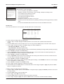
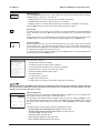
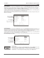
THE MENU SYSTEM
The MDR can be configured using a menu based system that can be viewed when the unit is connected to a monitor. The
menu system contains four pull-down menus and a number of pop-up menus.
Accessing the Menu System
The menu system is accessed by pressing the Menu button. A password dialog will appear on the primary
monitor. Use the Number buttons to enter one of the two available passwords. The Operator password
provides limited access to the menu system, and if this password is entered, only the Operator and
System View menus will be available. The Installer Password provides complete menu access. Default
passwords can be found on page 9.
Once a correct password has been entered, the menu system will be opened. There are four menus, and
each menu is covered in detail in this manual. Menus and menu items appear in the manual in the same
order they appear on-screen. The four available menus are as follows:
Main Menu
QuickInstall Menu
Operator Menu
SystemView Menu
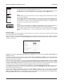
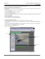
Navigating the Menu System
When the menu system is first accessed, only the menu bar is displayed. Use the Shuttle to move to the desired menu. To
open the highlighted menu, rotate the Jog.
Once the required drop-down menu is opened, rotate the Jog to move the cursor through the
items in it. A drop-down menu will look like the example on the left.
Time/Date
Sequencing
Record
Alarms
Macro
Motion Detection
Once the required option is highlighted in the drop-down menu, press the Enter button. This
will open up either a sub-menu, where further options are available, or a dialog. It is in these
dialogs that the MDR settings can actually be configured.
To return to the previous menu, press the Menu button.
Camera Setup
Archive Setup
Audio Setup
Telemetry
Communications
Front Panel Lock
Factory Settings
Passwords
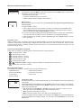
Dialogs usually have a parameter (or several parameters) from which the user can make a selection or change the value
of the parameter.
There are two types of dialog:
Time and Date Display
Monitor
Monitor
Monitor
Monitor
Monitor
[CANCEL]
A
B
C
D
E
:
:
:
:
:
ON
ON
ON
ON
ON
[OK]
Time Format Setup
Select Format
12 HOUR
The first type has [OK] or [CANCEL] options at the bottom.
Use the Jog to select the parameter that is to be changed, and then use the Shuttle to
change the value. To save the changes and exit the dialog, use the Jog to select [OK], then
press the Enter button. To exit the dialog without making changes, use the Jog to select
[CANCEL], then press the Enter button.
The Menu button can also be used to exit the dialog at any time.
The second type of dialog is different in that there are no [OK] or [CANCEL] options at the
bottom.
Use the Jog to change the value of the parameter. Press the Enter button to confirm the
selection and exit the dialog, or press the Menu button to exit the dialog without making
changes.
Once all the settings in a particular drop-down menu have been configured as required, press the Menu button to return to
the menu bar. From the menu bar, select another drop-down menu or press the Menu button again to exit the menu system
completely.
Note: There are a number of menu shortcuts that can be used. In dialogs that have two settings per camera, the Zoom
button can be used to toggle all selections. This provides a quick and easy way to enable or disable all cameras for a
particular feature. In dialogs that provide settings per camera, a particular camera may be accessed directly by pressing
the associated Number button. Rotate the Shuttle to modify the setting.
Page 23
MDR Series Multiplexed Digital Recorders
User Manual
THE MAIN MENU
Time/Date
Sequencing
Record
Alarms
Macro
Motion Detection
Camera Setup
Archive Setup
Audio Setup
Telemetry
Communications
Front Panel Lock
Factory Settings
Passwords
Page 24
User Manual
MDR Series Multiplexer Digital Recorders
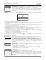
TIME/DATE
Time/Date Display
Set Time Format
Set Date Format
Set Time
Set Date
Set Master/Slave
Set Region
Network Time Setup
When the Time/Date menu item is selected from the Main menu, a sub-menu is displayed. From
this sub-menu, a user can specify:
Which monitor will display the time and date.
The time format: 12 or 24 hours.
The date format: MM/DD/YY, DD/MM/YY, or YY/MM/DD.
The time and date.
Whether the units clock is a master or slave.
The region and time zone.
Clock synchronisation between the MDR and a network server.
Time and Date Display
Monitor
Monitor
Monitor
Monitor
Monitor
A
B
C
D
E
:
:
:
:
:
[CANCEL]
ON
ON
ON
ON
ON
[OK]
Time Format Setup
Select Format
12 HOUR
Date Format Setup
Select Format
MM/DD/YY
Time Setup
HH
10
MM
13
[CANCEL]
SS
01
[OK]
Time/Date Display
This menu option displays the Time and Date Display dialog. It is used to specify which monitors
the time and date will be displayed on.
Use the Jog to navigate, then use the Shuttle to change the values. To save changes, use the
Jog to select [OK] and press the Enter button. To exit without saving changes, use the Jog to
select [CANCEL] and press the Enter button. Alternatively, press the Menu button.
Set Time Format
This menu option displays the Time Format Setup dialog. In this dialog, use the Jog to select
the desired time format. The options available are 12 HOUR and 24 HOUR
Press the Enter button to confirm the selection and exit the dialog, or press the Menu button to
exit the dialog without making changes.
Set Date Format
This menu option displays the Date Format Setup dialog. In this dialog, use the Jog to select
the desired date format. The options available are DD/MM/YY, MM/DD/YY and YY/MM/DD.
Press the Enter button to confirm the selection and exit the dialog, or press the Menu button to
exit the dialog without making changes.
Set Time
This menu option displays the Time Setup dialog, where the time can be set. To do this:
1. With HH MM SS highlighted, press the Enter button. The highlighting will move to the
row of numbers.
2. Enter the time in hours, minutes and seconds. Use the Jog to change the values.
Use the Shuttle to navigate among the three fields.
3. Press the Enter button to confirm the selection.
4. To save the changes and exit the dialog, use the Jog to select [OK], then press the
Enter button. To exit the dialog without making changes, use the Jog to select [CANCEL],
then press the Enter button.
Date Setup
MM
01
DD
01
[CANCEL]
YY
98
Day
MON
[OK]
Set Date
This menu option displays the Date Setup dialog, where the date can be set. To do this:
1. With MM DD YY DAY highlighted, press the Enter button. The highlighting will move to
the row of numbers.
2. Enter the date in months, days and years. The day of the week will update automatically. Use
the Jog to change the values. Use the Shuttle to navigate among the three fields.
3. Press the Enter button to confirm the selection.
4. To save the changes and exit the dialog, use the Jog to select [OK], then press the
Enter button. To exit the dialog without making changes, use the Jog to select [CANCEL],
then press the Enter button.
Page 25
MDR Series Multiplexed Digital Recorders
User Manual
TIME/DATE
Master/Slave Select
Master Clock
NO
Set Master/Slave
If several multiplexers are installed and connected via a RS485 network, one of the multiplexers
may be set as the master clock. This unit will control the date and time (including daylight savings
time) for all of the other units. To do this, use the Master/Slave Select dialog.
Select ONE unit from the RS485 network as the master clock by selecting YES in the dialog. All
other units must be set as NO (default setting). Press the Enter button to confirm the selection
and exit the dialog, or press the Menu button to exit the dialog without making changes.
Set Region
This menu option allows the user to select the region and time zone in which the MDR unit will be used.
Regional Settings
Daylight saving : EUR
Time Zone : GMT (+1)
SUN, 30 MAR 2003 02.48 (+1)
SUN, 26 OCT 2003 02.48 (-1)
[CANCEL]
[OK]
To configure the region and time zone settings, follow the steps below:
1. Using the Shuttle, set the relevant region for the Daylight Saving option. The options are:
OFF
USA (Areas within the North American continent)
EUR (Areas within the European continent)
AUS (Areas within the Australasian continent)
2. Use the Jog to navigate to the Time Zone.
3. Using the Shuttle, set the time zone in relation to GMT. The time zone must be set correctly to ensure that the DST
adjustments are made at the right time. It is also required for accurate email time stamping.
4. To save the changes and exit the dialog, use the Jog to select [OK], then press the Enter button. To exit the dialog
without making changes, use the Jog to select [CANCEL], then press the Enter button.
Note: The clock will only be automatically adjusted once on a given time and date. If the clock is manually set back before
the last DST change, the time will not get automatically adjusted again for that same time change.
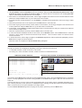
Network Time Protocol Setup
The unit can act as a Simple Network Time Protocol Client. When enabled, the MDR will retrieve the time and date from a
Network Time Protocol Server via UDP packet exchange and the user will never have to set the time manually. To set up
Network Time, select the Network Time Protocol Setup option. The Network Time Protocol Setup dialog is displayed:
Network Time Protocol Setup
Update Interval
NTP Primary Server
NTP Backup Server
:
:
:
DISABLE
10. 90.253. 10
255.255. 0. 0
[CANCEL]
[OK]
Last Update: Never since power-up
Warning: Region/Time Zone must be set correctly!
1. Set the Update Interval using the Shuttle. The options are Disable, Once per Day, Twice per Day and Once per Hour.
When Network Time is enabled, the unit retrieves the time after each power-up and periodically after the set period of
time has elapsed (i.e., 24 hours, 12 hours). The unit also retrieves the time whenever a user changes the settings in this
dialog (as long as Network Time is not disabled). To disable Network Time, set Update Interval to Disable.
2. Navigate to the NTP Primary Server option using the Jog. This field is used to set the primary NTP server address.
3. Use the Jog to select which part of the address is to be edited and use the Shuttle to adjust the values.
4. Navigate to the NTP Backup Server option using the Jog. This field is used to set the address of the backup NTP
server. This server will only be contacted when the primary server does not answer.
5. Use the Jog to select which part of the address is to be edited and use the Shuttle to adjust the values.
6. To save the changes and exit the dialog, use the Jog to select [OK], then press the Enter button. To exit the dialog
without making changes, use the Jog to select [CANCEL], then press the Enter button.
Note: The user must set the Regional Settings (see above) to the correct values when enabling Network Time.
Page 26
User Manual
MDR Series Multiplexer Digital Recorders
SEQUENCING
Multiscreen Dwell
Fullscreen Dwell
Group Switching
When the Sequencing menu item is selected from the Main menu, a sub-menu is displayed.
From this sub-menu, a user can:
Specify the multiscreen dwell time.
Specify the full screen dwell time.
Enable and setup Group Switching.
Multiscreen Dwell
(Time in Seconds)
03
Multiscreen Dwell
The multiscreen dwell time is the amount of time each camera in a multiscreen sequence is
displayed on-screen before the sequence advances to the next camera. It can be configured by
selecting this option. The Multiscreen Dwell dialog is displayed.
Rotate the Jog to change the dwell time (from 1 to 30 seconds). The default is 3 seconds. Press
the Enter button to confirm the dwell time and exit the dialog, or press the Menu button to exit the
dialog without making changes.
Fullscreen Dwell
(Time in Seconds)
03
Fullscreen Dwell
The full screen dwell time is the amount of time each camera in a full screen sequence is displayed
on-screen before the sequence advances to the next camera. It can be configured by selecting
this option. The Fullscreen Dwell dialog is displayed.
Rotate the Jog to change the dwell time (from 1 to 30 seconds). The default is 3 seconds. Press
the Enter button to confirm the dwell time and exit the dialog, or press the Menu button to exit the
dialog without making changes.
Group Switching
Group Switching is a feature that allows a user to display groups of four cameras on the four
auxiliary monitors (B-E). When the Group Switching menu item is selected, a sub-menu is
displayed. Use this sub-menu to:
Group Enable
Group Setup
Enable or disable Group Switching.
Setup Group Switching.
Group Switching
ENABLE
Group Enable
When this menu item is selected, the Group Switching dialog is displayed. Use this dialog to
enable or disable Group Switching.
Use the Jog to select the desired setting. Press the Enter button to confirm the selection and exit
the dialog, or press the Menu button to exit the dialog without making changes.
Activating Group Switching
When Group Switching is enabled, camera groups are set up and defined using the Alarm Action Setup dialog (see page
34). Once enabled, selecting any auxiliary monitor and starting or stopping sequence mode will make all the auxiliary
monitors start or stop sequencing as a group. To enter Group Switching mode, follow the steps below:
1. Select a monitor (B through E) by pressing the relevant Monitor button.
2. Press the Sequence button. Monitors B through E then begin simultaneous sequencing.
Group Switching can be deactivated by pressing the Sequence button again. Only selected monitors will run a sequence.
Group Switching Setup
Index : 01
Group : 01
[CANCEL]
[OK]
Group Setup
Select this menu item to display the Group Switching Setup dialog. This dialog allows the user
to specify the order in which camera groups are switched. The Index parameter denotes the
entry in the list, the Group parameter denotes the camera group that will be selected. Groups are
defined in the Alarm Action Setup dialog (see page 34).
Use the Shuttle to select an Index number. Use the Jog to navigate to the Group parameter and
then use the Shuttle to select the camera group that is to be placed in that position. Repeat this
procedure to compile the Group Switching list index by index. When the list is complete, terminate
it by selecting the blank value in the Group parameter.
Example: The user wants to select three groups in the following order: 1, 2, 1, 2, 3. The Group
Switching setup list would look like this as it is stepped through:
Index
01 02 03 04 05 06
Group
01 02 01 02 03
To save the changes and exit the dialog, use the Jog to select [OK], then press the Enter button.
To exit the dialog without making changes, use the Jog to select [CANCEL] and then press the
Enter button.
Page 27
MDR Series Multiplexed Digital Recorders
User Manual
RECORD
Record Timer
Record Quality
Event Settings
Timelapse Record Rate
Event Record Rate
Activity Record Rate
Alarm Record Rate
Record Mode
Disk Maintenance
Record Lock
Auto Delete Mode
When the Record menu item is selected from the Main menu, a sub-menu is displayed. From
this sub-menu, a user can specify:
The record quality: High, Medium or Standard.
Whether a camera is to be used for event recording, timelapse recording or both.
The Timelapse Record Rate per camera.
The Event Record Rate per camera.
The Activity Record Rate per camera.
The Alarm Record Rate.
Whether the Record Lock feature is to be used.
Whether to perform disk maintenance by deleting, undeleting or destroying previously recorded
video.
How the unit will handle data overwrite issues once the hard disk becomes full.
Record Timer
This menu item allows the user to program, edit and delete timer-recorded events.
Date
Start
Stop
Macro
ON/OFF
31
SAT
MON-FRI
SAT-SUN
MON-SUN
--
16:45
07:55
09:56
14:23
02:23
--:--
17:05
08:10
11:05
14:50
03:34
--:--
NONE
10
NONE
NONE
NONE
–-
ON
OFF
ON
ON
OFF
–
[OK]
Hit “ENTER” to Toggle EDIT Mode
To create a timed recording, follow the steps below:
1. Using the Jog to navigate, highlight the Date parameter of the last line item (indicated with double dash
marks).
2. Press the Enter button to enter the Edit mode. The user may press the Enter button to exit Edit mode at any time.
3. Use the Jog to change the values of the Date setting. The values available are:
Date (Day of the Month) - 1 through 31
Day of the Week - Monday through Sunday
Range of Days - All Weekdays (Monday-Friday), All Weekend Days (Saturday-Sunday), Monday-Sunday (Everyday)
4. Use the Shuttle to navigate to the Start setting.
5. Use the Jog/Shuttle to enter the time the recording will begin. The hours and minutes are edited separately. The
start and stop times are always configured in a 24-hour clock.
6. Use the Shuttle to navigate to the Stop setting.
7. Use the Jog/Shuttle to enter the time the recording will end. Entering a time before the start time will cause the unit
to record until the indicated stop time on the next day.
8. Use the Shuttle to navigate to the Macro setting.
10. Use the Jog to select a macro number that will run during this recording, or select NONE is no macro is to run. See page
38 for more details on creating macros.
11. Use the Shuttle to navigate to the ON/OFF setting.
12. Use the Jog to activate, deactivate or delete the recording.
13. When finished, press the Enter button to exit the Edit mode. Use the Jog to navigate to [OK], then press the Enter
button to complete the selection.
To delete a timed recording, follow the steps below:
1. Using the Jog to navigate up/down and the Shuttle to navigate left/right , highlight the ON/OFF parameter of the event
you wish to delete.
2. Press the Enter button to enter the Edit mode.
3. Use the Jog to select DEL from the menu.
4. Press the Enter button to confirm the selection and exit the Edit mode.
5. Use the Jog to navigate to [OK], then press the Enter button to remove the selection and exit the dialog.
Page 28
User Manual
MDR Series Multiplexer Digital Recorders
RECORD
Record Quality
Camera 01 : High
Camera 02 : High
Camera 03 : High
:
:
Camera 16 : High
[CANCEL]
[OK]
Record Quality
Use this menu item to specify the record quality for each camera. Decreasing the record quality
decreases the amount of disk space required to store the images, due to a higher compression
scheme.
Use the Jog to move between cameras, setting the record quality for each one using the Shuttle.
High record quality provides the best picture quality but uses the most disk spaceLow record
quality provides fair picture quality but uses the least disk space.
To save the changes and exit the dialog, use the Jog to select [OK], then press the Enter button.
To exit the dialog without making changes, use the Jog to select [CANCEL], then press the
Enter button.
Event Settings
An Event is an action that the unit acknowledges by recording at the Event Record Rate. An event is not the cause for an
alarm. Events may be created in two ways, via RS232 text insertion or by activity detection. Use this sub-menu to specify
how each camera will record during normal and event conditions.
Event Camera Settings
Camera
Type
Pre Event Duration
Post Event Duration
Event Associated Cameras
[CANCEL]
:
:
:
:
:
01
Event + TL
00
000
-- -- --
[OK]
An example of an event could be if a camera is pointed at the front door inside a lobby during business hours. With the Type
field in this sub-menu set to Event, the unit does not record while the doorway is empty. When activity motion detection
senses that someone is entering or leaving the doorway, the unit begins recording at the Event Record Rate and stops
recording when the motion ceases.
To configure the event camera settings, follow the steps below:
1. Using the Jog to navigate, highlight the Camera parameter.
2. Using the Shuttle, select the camera number that is to be edited.
3. Using the Jog to navigate, highlight the Type parameter.
4. In the Type parameter, use the Shuttle to select how the camera will record during normal and event conditions. Select
from:
TL: Record at the Timelapse Record Rate under normal conditions. Does not change record rate during an event.
If this option is selected, it is not necessary to complete any further fields in this dialog.
Event: Record during events at the Event Record Rate. Camera does not record under normal conditions.
Event + TL: Record at the Timelapse Record Rate under normal conditions. Records at the Event Record Rate
during events.
5. Use the Jog to navigate to the Pre Event Duration parameter.
6. Use the Shuttle to specify the period of time the unit should record data ahead of an event trigger, at the Event Record
Rate. Select from 0 to 5 seconds.
7. Use the Jog to navigate to the Post Event Duration parameter.
8. Use the Shuttle to specify the period of time the unit should record data after the completion of an event, at the Event
Record Rate. Select from 0 to 250 seconds.
9. Use the Jog to navigate to the Event Associated Cameras parameter.
10. Using the Jog to navigate in the parameter and the Shuttle to adjust values, enter up to three camera numbers to be
associated with this event.
11. Repeat steps 1-10 to set parameters for further cameras.
12. When configuration is complete, use the Jog to navigate to [OK], then press the Enter button to complete the selection.
Page 29
MDR Series Multiplexed Digital Recorders
User Manual
RECORD
Timelapse Record Rate
When this menu item is selected, the Timelapse Record Rate dialog is displayed. This dialog is used to specify the
Timelapse Record Rate for each camera. This is the rate is at which the unit records under normal conditions, when there
are no alarms, events, or activity present. Record rates are measured in both pictures per second (pps) and seconds per
picture (spp).
Timelapse Record Rate
Camera 01 : 0.40
Camera 02 : 0.29
Camera 03 : 0.34
:
:
Camera 16 : 0.40
pps 2.5 spp
pps 3.5 spp
pps 2.9 spp
pps 2.5 spp
[CANCEL] [OK]
8 days 5 h (TL)
8 days 5 h (Total)
The maximum record rate per camera is inversely proportional to the number of cameras connected to the unit. The fewer
cameras connected, the higher the maximum record rate for each camera, and vice versa. The maximum record rate for
multiple cameras is 40pps PAL (48pps NTSC). The maximum record rate for a single camera is 25pps PAL (30pps NTSC).
The bottom right corner of the menu contains a record duration calculator. The top line indicates the estimated recording
time for the unit in Timelapse record mode only. The bottom line indicates the estimated recording time, taking into
consideration the amount of time the unit will spend in Activity, Event, and/or Alarm record modes.
To change the settings in this dialog, rotate the Jog to select the required camera, and use the Shuttle to change the
values for that camera. To save changes and exit the dialog, use the Jog to select [OK] and then press the Enter button.
To exit the dialog without making changes, use the Jog to select [CANCEL] and then press the Enter button. Alternatively,
just press the Menu button.
Event Record Rate
When this menu item is selected, the Event Record Rate dialog is displayed. This dialog is used to specify the Event
Record Rate for each camera. This is the rate is at which the unit records when an event is activated, by either an RS232
event generation or by activity detection. Record rates are measured in both pictures per second (pps) and seconds per
picture (spp).
Event Record Rate
Camera 01 : 0.40
Camera 02 : 0.29
Camera 03 : 0.34
:
:
Camera 16 : 0.40
pps 2.5 spp
pps 3.5 spp
pps 2.9 spp
%Time: 4%
Estimate of the % of time each camera
will spend in Event mode. For example,
if you expect to have about 20 total
pps 2.5 spp
[CANCEL] [OK]
125 days 8 h (EVENT)
10 days 7 h (Total)
events each day, each lasting 3 minutes
on average, then the % of time will be
4% (1 hour/24 hours)
The maximum record rate per camera is inversely proportional to the number of cameras connected to the unit. The fewer
cameras connected, the higher the maximum record rate for each camera, and vice versa. The maximum record rate for
multiple cameras is 40pps PAL (48pps NTSC). The maximum record rate for a single camera is 25pps PAL (30pps NTSC).
The bottom right corner of the dialog contains a record duration calculator. The top line indicates the estimated recording
time of the cameras in Event record mode only. The bottom line indicates the estimated recording time, taking into
consideration the amount of time the unit will spend in Timelapse, Activity, Event, and/or Alarm record modes.
To change the settings in this dialog, rotate the Jog to select the required camera, and use the Shuttle to change the
values for that camera. It is also possible to adjust the %Time parameter using the Shuttle.
To save changes and exit the dialog, use the Jog to select [OK] and then press the Enter button. To exit the dialog without
making changes, use the Jog to select [CANCEL] and then press the Enter button. Alternatively, just press the Menu
button.
Page 30
User Manual
MDR Series Multiplexer Digital Recorders
RECORD
Activity Record Rate
When this menu item is selected, the Activity Record Rate dialog is displayed. This dialog is used to specify the Activity
Record Rate for each camera. This is the rate is at which the unit records when the camera is in normal Timelapse Record
Mode and activity is detected in the camera scene. Activity should not be linked to an Event, in which case the Event
Record Rate will be used. Record rates are measured in both pictures per second (pps) and seconds per picture (spp).
Activity Record Rate
Camera 01 : 0.40
Camera 02 : 0.29
Camera 03 : 0.34
:
:
Camera 16 : 0.40
pps 2.5 spp
pps 3.5 spp
pps 2.9 spp
%Time: 4%
will spend in periods of activity. For
example, if you expect to have about 20
total periods of activity each day, each
pps 2.5 spp
[CANCEL] [OK]
Estimate of the % of time each camera
lasting 3 minutes on average, then the %
125 days 8 h (ACTIVITY)
10 days 7 h (Total)
of time will be 4% (1 hour/24 hours)
The maximum record rate per camera is inversely proportional to the number of cameras connected to the unit. The fewer
cameras connected, the higher the maximum record rate for each camera, and vice versa. The maximum record rate for
multiple cameras is 40pps PAL (48pps NTSC). The maximum record rate for a single camera is 25pps PAL (30pps NTSC).
The bottom right corner of the dialog contains a record duration calculator. The top line indicates the estimated recording
time of the cameras in Activity record mode only. The bottom line indicates the estimated recording time, taking into
consideration the amount of time the unit will spend in Timelapse, Activity, Event, and/or Alarm record modes.
To change the settings in this dialog, rotate the Jog to select the required camera, and use the Shuttle to change the
values for that camera. It is also possible to adjust the %Time parameter using the Shuttle.
To save changes and exit the dialog, use the Jog to select [OK] and then press the Enter button. To exit the dialog without
making changes, use the Jog to select [CANCEL] and then press the Enter button. Alternatively, just press the Menu
button.
Alarm Record Rate
When this menu item is selected, the Alarm Record Rate dialog is displayed. This dialog is used to specify the Alarm
Record Ratethe rate at which the unit records during an alarm.
Global Alarm Record Rate
% Time: 1%
60 pps
40 days 20 h (Alarm)
15 days 11 h (Total)
[CANCEL]
Estimate of the % of time the unit will
typically spend in alarm mode. For example if
you expect to have about 5 total periods of
alarms each day, each lasting 3 minutes on
average, then the % of the time will be 1%.
(15 mins/24 hours)
Record Duration Calculator
[OK]
The bottom of the dialog contains a record duration calculator. The top line indicates the estimated recording time of the
cameras in Alarm record mode only. The bottom line indicates the estimated recording time, taking into consideration the
amount of time the unit will spend in Timelapse, Activity, Event, and/or Alarm record mode.
To adjust the %Time and Pictures Per Second (pps) parameters, navigate using the Jog and use the Shuttle to change
the values. To save changes and exit the dialog, use the Jog to select [OK] and then press the Enter button. To exit the
dialog without making changes, use the Jog to select [CANCEL] and then press the Enter button. Alternatively, just press
the Menu button.
Note: The configuration of the Alarm Record Rate is closely associated with the Alarm Record Mode. For detailed information
about configuring the Alarm Record Mode, see page 35.
No overwrite
Write once
Continuous
Record Mode
When this menu item is selected, a sub-menu is displayed with three options. Use this sub-menu
to specify how the unit will handle data overwrite issues once the hard disk becomes full. The
MDR can handle disk overwrite issues in three ways:
No Overwrite
Write Once
Continuous Overwrite
See overleaf for more details about the three disk overwrite modes.
Use the Jog to select the required setting. To confirm the selection and exit the sub-menu, press
the Enter button. To exit the sub-menu without making changes, press the Menu button.
Page 31
MDR Series Multiplexed Digital Recorders
User Manual
RECORD
No Overwrite
When No Overwrite mode is selected, the MDR will function
as follows:
P
rec revi
or o
de
ecorded da
ta
wr
e
N
sly ta
ou da
ed
P
rec rev
or i
d
Recording always starts at end of last recording.
Recording stops when end of disk is reached (when disk
is full).
When the end of the disk is reached, the unit displays an
on-screen message indicating that the disk is full, and
the unit has stopped recording. User must acknowledge
the on-screen message by pressing the Enter button.
The MDR will not record over previously recorded
data. To continue recording, the data must be erased (or
deleted). See Disk Maintenance on page 33 for details
on how to do this.
ly
us data
d
Unit stops
Recording when this
point is reached
Physical Start
and End of disk
No Overwrite Mode
Write Once
When Write Once mode is selected, the MDR will function
as follows:
P
rec re
o v e or
r
ecorded da
ta
wr
e
N
Recording always starts at end of last recording.
The unit overwrites all previously recorded data.
Recording stops before the unit overwrites any of the new
recorded data (data from the current record session).
When the end of the disk is reached, the unit displays an
on-screen message indicating that the disk is full, and
the unit has stopped recording. User must acknowledge
the on-screen message by pressing the Enter button.
Unit stops
Recording
when this
point is
reached
The unit will continue recording again when the user
presses the Record button.
sly
ou ata
vi ed d en
d ritt
w
Physical
Start of disk
Continuous Overwrite Mode
When Continuous Overwrite mode is selected, the MDR
will function as follows:
ly
us ata
io d d n
e itte
r
ten
Ne
w
ed data ove
ord
rw
c
e
rit
r
Write Once Mode
P
rec rev
o
o ve r d
rw
Unit records over
all recorded data
Continuous Overwrite Mode
Page 32
Recording always starts at end of last recording.
The unit overwrites all previously recorded data.
The unit overwrites new recorded data (data from the
current record session).
Unit never stops recording.
User Manual
MDR Series Multiplexer Digital Recorders
RECORD
Disk Maintenance
In the Disk Maintenance sub-menu, use the Jog to move between the following options, pressing
the Enter button to select one. The user can:
Delete
UnDelete
Destroy
Delete all data from the hard disk (with the possibility of restoring it).
Undelete data that has been deleted, but not yet overwritten.
Destroy all data on the hard disk permanently (removed with no possibility of restoring it).
Press the Menu button to leave the sub-menu without selecting an option.
Record Lock
Use this menu item to set the Record Lock feature. This feature disables the front panel Record
button. Setting Record Lock to ON will start the unit recording if it is not currently in the Record
mode.
OFF
ON
Use the Jog to select the required setting. To confirm the selection and exit the sub-menu, press
the Enter button. To exit the sub-menu without making changes, press the Menu button.
Auto Delete Mode
By selecting this menu item, the Auto Delete function can be set. Use the Jog to select a number
of days (between 7 - 99). Data older than the number of days selected will automatically be
prevented from being displayed. Or select OFF if this function is not to be used. This feature may
be required by law under the Data Protection Act.
ADM Setting
99 Days
To confirm the selection and exit the dialog, press the Enter button. To exit the dialog without
making changes, press the Menu button.
ALARMS
Input Configuration
Alarm Latch
Alarm Action
Alarm Record Mode
Enable / Disable
Alarm History
Link to a Macro
Fullscreen Alarm
Relay Configuration
Buzzer Setup
Videoloss Action
Pre Alarm Duration
Notification
Archive Alarms
When the Alarms menu item is selected from the Main menu, a sub-menu is displayed. From
this sub-menu, a user can:
Configure alarm inputs and outputs.
Configure how the unit latches alarm conditions.
Set up what action takes place when an alarm is triggered.
Determine how the unit will record cameras in alarm.
Enable and disable individual alarm inputs.
View alarm histories.
Link alarm inputs to macros.
Configure the internal buzzer.
Configure video loss alarms, archive alarms and alarm notifications.
The primary function of the MDR is to furnish video multiplexing and recording with a multiscreen display. Although
the unit has alarm handling and motion detection functions, these are considered secondary features. This unit
should not be the only alarm device on site.
Alarm Input
Alarm 01 : N/OPEN
Alarm 02 : N/OPEN
Alarm 03 : N/CLOSED
:
:
Alarm 16 : N/OPEN
[CANCEL]
[OK]
Input Configuration
When this menu item is selected, the Alarm Input dialog is displayed. Use it to configure each
alarm input as either Normally-Open or Normally-Closed.
Use the Jog to move between inputs, setting the status for each one using the Shuttle. To save
the changes and exit the dialog, use the Jog to select [OK], then press the Enter button. To exit
the dialog without making changes, use the Jog to select [CANCEL], then press the Enter
button.
The different types of alarm Inputs should be configured as follows:
Normally Open Zero Potential Relay Contact: Normally-Open.
Normally Closed Zero Potential Relay Contact: Normally-Closed
TTL Active High: Normally-Closed
TTL Active Low: Normally-Open
Open Collector Active On: Normally-Open
Open Collector Active Off: Normally-Closed
Page 33
MDR Series Multiplexed Digital Recorders
User Manual
ALARMS
Latched
Transparent
Timed Out
Alarm Latch
Select this menu item to determines how the unit latches alarm conditions. Use the Jog to select
the required setting. To confirm the selection and exit the sub-menu, press the Enter button. To
exit the sub-menu without making changes, press the Menu button.
The following settings are available:
Latched: The alarm is activated until it is silenced and acknowledged by the user.
Transparent: The alarm is active only while receiving alarm input. The alarm condition is
cancelled when the alarm input ceases.
Timed Out: The alarm condition is latched for the amount of time selected in this menu, then
it is automatically silenced and acknowledged. If the alarm input exceeds the duration specified
in this menu, the unit silences and acknowledges the alarm when the alarm input ceases.
Select the timeout duration in the dialog that is displayed when Timed Out is selected. The
range is from 1 to 250 seconds.
Note: Transparent alarms cannot be silenced and acknowledged. If transparent mode is preferred,
but the ability to silence and acknowledge alarms is desired, select Timed Out and set the Alarm
Timeout to two seconds.
Alarm Action
Select this menu item to display the Alarm Action Setup dialog. This dialog is used to specify what action is initiated when
an alarm input is triggered.
Alarm Action Setup
Input
Freeze
Cameras
Presets
Relay
Intrusion AND/OR
Aux Monitor
[CANCEL]
:
:
:
:
:
:
:
01
Yes
01 16 02 03
01 -- 09 -1
OR
B
[OK]
To configure the action for an alarm input, follow the steps below:
1. With the Input parameter highlighted, use the Shuttle to select the alarm input number that is to be configured.
2. Using the Jog to navigate, highlight the Freeze parameter.
3. Use the Shuttle to set the Freeze parameter to Yes or No. Selecting Yes will freeze the alarm camera display (quadrant
1) at the time the alarm is activated.
4. Use the Jog to navigate to the Cameras parameter.
5. Using the Shuttle, specify up to four cameras that will be displayed on-screen when the alarm is received. The camera
group should contain the camera in alarm and three associated cameras.
By default, the first camera in the list is the camera in alarm. The second camera is the camera that precedes the alarm
camera numerically. The third and fourth cameras are the two cameras following the alarm camera numerically.
The camera group selected here can also be used for Group Switching. The camera group is identified by the Input
number (i.e., camera group selected for Input number 1 is identified as Camera Group 1). See page 27 for details.
6. Use the Jog to navigate to the Presets parameter.
7. Use the Shuttle to select preset positions that the specified cameras preset are to sent to when an alarm is activated.
The preset number corresponds with the camera number located directly above it in this menu. Select from 1 through
16. If this field is left blank, the camera will not move to a preset position.
In the example above, Camera 1 will go to Preset 1, while Camera 2 will go to Preset 9.
8. Use the Jog to navigate to the Relay parameter.
9. Using the Shuttle, configure which relay will be triggered when an alarm is activated. Select from 1, 2, 1 + 2 and
NONE.
10. Use the Jog to navigate to the Intrusion AND/OR parameter.
11. Use this feature to activate alarms by hardwire alarm inputs AND/OR Intrusion detection. Use the Shuttle to select AND
or OR. To use the feature, Motion Detection must be set to Intrusion and linked to this alarm number (see page 40).
12. Use the Jog to navigate to the Aux Monitor parameter.
13. Use the Shuttle, to designate on which auxiliary monitor the alarm is to be viewed. Select from B, C, D and E.
14. Repeat steps 1-13 to set parameters for further alarm inputs.
15. When configuration is complete, use the Jog to navigate to [OK], then press the Enter button to complete the selection.
Page 34
User Manual
MDR Series Multiplexer Digital Recorders
ALARMS
Alarm Record Mode
Select Mode
INTERLEAVED
Alarm Record Mode
Use this menu item to determine how the unit will record cameras in alarm. Use the Jog to select
the required mode. To confirm the selection and exit the dialog, press the Enter button. To exit
the dialog without making changes, press the Menu button.
The following modes are available:
NO CHANGE: Unit changes to the Alarm Record Rate, but it does not give priority to the
camera in alarm.
EXCLUSIVE: The unit records only cameras in alarm.
INTERLEAVED: Alarmed cameras are recorded at a higher rate than non-alarm cameras.
The unit accomplishes this by interleaving images of alarmed cameras between images from
non-alarmed cameras in the record list. Interleaved is the recommended mode of operation.
Example of Alarm Record Modes
Individual Enable
Enable All
Disable All
Alarms Enable
Alarm 01 : ENABLE
Alarm 02 : DISABLE
Alarm 03 : ENABLE
:
:
Alarm 16 : DISABLE
[CANCEL]
[OK]
Alarms History
001- 02/04 18:40:32 16
002- 02/15 12:00:10 11
003- 02/28 10:10:20 08
:
:
010- 03/15 05:12:16 04
No Change mode with 8 cameras, Camera 4 in alarm
1234567812345678
Exclusive mode with 8 cameras, Camera 4 in alarm
4444444444444444
Interleaved mode with 8 cameras, Camera 4 in alarm
1424345464748414
Enable / Disable
Use this menu item to enable or disable alarm inputs. In this menu, the user can select to:
Enable All: Enable all alarm inputs.
Disable All: Disable all alarm inputs.
Individual Enable: Allow the user to access the Alarm Enable dialog, and enable or
disable alarm inputs on a per camera basis. In this dialog, rotate the Jog to navigate
between alarm inputs, using the Shuttle to enable or disable each input.
To save the changes and exit the dialog, use the Jog to select [OK], then press the Enter
button. To exit the dialog without making changes, use the Jog to select [CANCEL], then
press the Enter button.
Alarm History
Select this menu item to view a list of the 100 most recent alarms. Alarms are displayed 10 at a
time. Rotate the Jog to scroll through the alarms.
Each item in the list comprises the alarm number, the date of the alarm, the time of the alarm and
the number of the camera input in alarm.
To leave the dialog, use the Jog to select [OK], then press the Enter button.
[OK]
Macro Link List Setup
Alarm
01
02
03
16
_
_
_
_
_
_
_
[CANCEL]
Macro
01
02
04
09
[OK]
Fullscreen Alarm
Fullscreen
NO
Link To A Macro
Select this menu item to link an alarm input to a macro. If a link is created, the selected macro will
run each time that alarm is activated.
Rotate the Jog to highlight the required alarm input and use the Shuttle to select a macro to link
to this input. Leave the macro value blank if an alarm input is to remain unlinked.
To save the changes and exit the dialog, use the Jog to select [OK], then press the Enter button.
To exit the dialog without making changes, use the Jog to select [CANCEL], then press the
Enter button.
Fullscreen Alarm
Use this menu item to select whether alarms should be displayed as a full screen display or a 4way multiscreen display. Using the Jog to select Yes will cause the unit to always display the
alarm camera full screen. Selecting No from this menu will cause the unit to display the 4-way
display configured in the Alarm Action Setup menu (see page 34 for more details).
To confirm the selection and exit the dialog, press the Enter button. To exit the dialog without
making changes, press the Menu button.
Page 35
MDR Series Multiplexed Digital Recorders
User Manual
ALARMS
Relay Configuration
Relay A : N/OPEN
Relay B : N/CLOSED
[CANCEL]
[OK]
To save the changes and exit the dialog, use the Jog to select [OK], then press the Enter button.
To exit the dialog without making changes, use the Jog to select [CANCEL], then press the
Enter button.
Buzzer Setup
Global Buzzer
Live Alarm Buzzer
Videoloss Buzzer
Playback Buzzer
[CANCEL]
Relay Configuration
When this menu item is selected, the Relay Configuration dialog is displayed. Use this dialog to
configure each relay output as either Normally-Open or Normally-Closed. Use the Jog to move
between the two relays, setting the status for each one using the Shuttle.
:
:
:
:
[OK]
ON
ON
ON
ON
Buzzer Setup
When this menu item is selected, the Buzzer Setup dialog is displayed. Use this dialog to configure
the internal buzzer. Use the Jog to move between the four options, using the Shuttle to turn
each one ON or OFF.
The four options are:
Global Buzzer: This setting acts as a master on/off switch. Setting this option to OFF deactivates
all buzzer activity.
Live Alarm Buzzer: Set this option to ON to activate the buzzer whenever the unit receives an
alarm input.
Videoloss Buzzer: Set this option to ON to activate the buzzer whenever video loss is detected.
Disabling the videoloss buzzer disables all videoloss buzzer activity. Videoloss buzzers may
also be disabled on a per camera basis in the Videoloss Action dialog (see below).
Playback Buzzer: Set this option to ON to activate the buzzer during playback of recorded
alarms.
To save the changes and exit the dialog, use the Jog to select [OK], then press the Enter button.
To exit the dialog without making changes, use the Jog to select [CANCEL], then press the
Enter button.
Videoloss Action
Camera
Relay 1
Relay 2
Buzzer
:
:
:
:
[CANCEL]
01
DISABLE
ENABLE
ENABLE
[OK]
Videoloss Action
Select this menu item to configure how the unit responds to video loss from each individual
camera.
With the Camera parameter highlighted, use the Shuttle to select the camera that is to be
configured. Then using the Jog to navigate and the Shuttle to adjust the values, configure the
following fields for the selected camera:
Relay 1: If the relay is enabled, it will be activated when video loss is detected on this camera.
Relay 2: If the relay is enabled, it will be activated when video loss is detected on this camera.
Buzzer: Use this setting to disable the videoloss buzzer activation on a per camera basis. To
disable videoloss buzzer activation on all cameras go to the Buzzer Setup menu, described
above.
To save the changes and exit the dialog, use the Jog to select [OK], then press the Enter button.
To exit the dialog without making changes, use the Jog to select [CANCEL], then press the
Enter button.
Pre Alarm Duration
(Time in Seconds)
03
Pre Alarm Duration
During recording, the unit stores up to 5 seconds of recorded information in a buffer. This data
can be automatically retrieved when an alarm is activated. In this dialog, specify the amount of
time just previous to the activation of an alarm you wish to retrieve.
Use the Jog to specify the number of seconds. To confirm the selection and exit the dialog, press
the Enter button. To exit the dialog without making changes, press the Menu button.
Email
TCP/IP
Notification
Use this sub-menu to set up:
Email Notification
TCP/IP Notification
Page 36
User Manual
MDR Series Multiplexer Digital Recorders
ALARMS
Email Notification
When the Email option is selected in the Notification sub-menu, the Email Notification Setup dialog is displayed. This
dialog allows the user to setup the types of events to be notified of, and the email addresses (up to two) to be notified.
Use the Jog to navigate between fields. The Notify.. and SMTP.. parameters can be adjusted using the Shuttle. To
configure the Email.. parameters, follow the context sensitive on-screen instructions.
To save the changes and exit the dialog, use the Jog to select [OK], then press the Enter button. To exit the dialog without
making changes, use the Jog to select [CANCEL], then press the Enter button.
Note: The Region/Time Zone setting must be set correctly for Email notification to time stamp messages accurately. See
page 26 for more details.
Email Notification Setup
One or more of these fields
must be set to ENABLE to
receive an email notification
of the selected event.
Email address format is
user@domain
Obtain the parameters for these
fields from your IT department
Notify Vidloss:
Notify Alarm:
Notify Record:
Notify Archive:
Notify Menu Access:
Notify Power Up:
Notify Connection:
Email User 1:
Email Domain 1:
Email User 2:
Email Domain 2:
SMTP Server:
SMTP Port
ENABLE
DISABLE
DISABLE
DISABLE
DISABLE
DISABLE
DISABLE
john.doe
somecompany.com
jane.doe
somecompany.com
0. 0. 0. 0.
25
[CANCEL]
[OK]
Format of email address: user@domain
Warning: Region/Time Zone must be set correctly!
TCP/IP Notification
When the TCP/IP option is selected in the Notification sub-menu, the TCP/IP Notification Setup dialog is displayed. This
dialog allows the user to setup the types of events to be notified of, and the IP addresses (up to two) of the PCs where the
WaveReader software resides. Use the Jog to navigate between fields and the Shuttle to adjust values.
To save the changes and exit the dialog, use the Jog to select [OK], then press the Enter button. To exit the dialog without
making changes, use the Jog to select [CANCEL], then press the Enter button.
Note: WaveReader must be running on the receiving PCs and Alarm Monitoring must be setup. See Alarm Monitoring in
the WaveReader Manual for details.
TCP/IP Notification Setup
One or more of these fields
must be set to ENABLE to
receive notification of the
selected event.
IP addresses of the PCs on
which the WaveReader
Software resides
Set from 1 to 60 minutes, or
immediately upon event.
Notify Vidloss:
Notify Alarm:
Notify Record:
Notify Archive:
Notify Menu Access:
Notify Power Up:
Notify Connection:
Primary Host:
Backup Host:
Port:
Notification Interval (minutes):
[CANCEL]
Archive Alarms
Relay 2
ENABLE
ENABLE
DISABLE
DISABLE
DISABLE
DISABLE
DISABLE
DISABLE
0. 0. 0.
0. 0. 0.
1027
Immediate
0
0
[OK]
Archive Alarms
Select this menu item to display the Archive Alarms dialog. Selecting ENABLE in this menu
item will cause the unit to activate relay 2 if a malfunction occurs while archiving.
Use the Jog to enable or disable this feature. To confirm the selection and exit the dialog, press
the Enter button. To exit the dialog without making changes, press the Menu button.
Page 37
MDR Series Multiplexed Digital Recorders
User Manual
MACRO
Macro Record
Timed Macro Start
Edit Submacro
A macro is a recorded sequence of keystrokes. Each of the 16 available macros can have up to
32 keystrokes. When the Macro menu item is selected from the Main menu, a sub-menu is
displayed. From this sub-menu, a user can:
Enter Macro Record mode.
Program a scheduled start time for a macro.
Edit the RS232 command string for each submacro.
Macro Record
Select Macro
01
Macro Record
Select this menu item to record a macro. Do not attempt macro programming while the front
panel is locked.
To begin recording a macro:
1. Use the Jog to select the macro number you wish to record, then press the Enter button.
The unit will automatically exit the menu system and go to a starting point. Macro Record
mode is indicated as F and the Macro Number on-screen.
2. From this point, begin recording the desired keystroke sequence. Record up to 32 keystrokes.
If 32 keystrokes are exceeded, the unit will end the macro recording automatically.
3. When programming is complete, press the Function button then the Enter button to end the
macro recording.
Keystroke Count
While recording a macro, entering the menu system, changing multiple menu items, and exiting the menu system are only
counted as one keystroke. Using the Jog to navigate the menu system does not count as a keystrokes. Once the menu
system has been exited, re-entering the menu system will count as a second keystroke. Not all menu items can be
programmed using macros.
Special Keys During Macro Recording
During macro recording, the following button combinations perform special functions:
{F}
+ 1: Activate Relay 1 output
{F}
+ 2: Reset Relay 1 output
{F}
+ 3: Pause macro for 1 second
{F}
+ 4: Pause macro for 5 seconds
{F}
+ 5: Activate Relay 2 output
{F}
+ 6: Reset Relay 2 output
{F}
+
{F}
+ Enter button: End macro recording
{F}
+ Submacro number: Program a specific submacro to activate when the macro is run
Macro Excluded Features
The following core features or settings cannot be programmed by macro:
Disk Maintenance
RS485 Network Address
Erase Archive Medium
Front Panel Lock/Unlock
POTS Setting
Record Timer
Ethernet Setting
Timed Macro Setup
Event
Day
Time
Macro
:
:
:
:
[CANCEL]
01
Monday
00:00
01
[OK]
Timed Macro Start
Select this menu item to create scheduled events. Up to 20 scheduled events can be programmed
in this menu.
With the Event parameter highlighted, use the Shuttle to select the event that is to be configured.
Then using the Jog to navigate and the Shuttle to adjust the values, configure the following
fields for the selected event:
Day: Select the start day (Monday Sunday) of the event. Select the ** option to run the
event every day or select None to cancel the scheduled start time.
Time: Specify the start time for the macro.
Macro: Select the number of the macro that is to run during this event.
To save the changes and exit the dialog, use the Jog to select [OK], then press the Enter button.
To exit the dialog without making changes, use the Jog to select [CANCEL], then press the
Enter button.
Page 38
User Manual
MDR Series Multiplexer Digital Recorders
MACRO
Submacro Edit
Select Submacro
01
Edit Submacro
A submacro is an RS232 command string that is used to control a peripheral device. Submacros
are activated during macros. See page 38 for information about programming a macro to activate
a submacro.
In the Submacro Edit dialog, use the Jog to select the submacro you wish to edit and press the
Enter button. This dialog will appear:
Edit Submacro 01
080 066 066 037 --- --- --- --- --- --[P] [B] [B] [%]
[CANCEL]
[OK]
ENTER key starts submacro edit
Use this dialog to create the RS232 command string. Press the Enter button to enter and exit the submacro edit mode.
Rotate the Shuttle to navigate among the fields and use the Jog to change the values. Each byte value can be set from 0
to 255. To save the sub-macro, use the Jog to navigate to [OK] and press the Enter button.
Running A Macro
To activate a macro, press the Function button followed by the Number button of the desired
macro. While running, the macro is indicated on-screen as the letter F and the macro number.
The user can cancel the macro at any time by pressing the Function button.
{F}
1
Daylight Savings Time (Alternate Method)
A macro is provided for the adjustment of the time by one hour for daylight savings time. Press
the Function button, then the Sequence button. If this function is activated during April, one hour
is added to the time. If this function is activated in October, one hour is subtracted from the time.
This function will only operate once per time period.
{F}
MOTION DETECTION
Enable/Disable Detection
Setup Parameters
Setup Active Zones
Indicate Detection
When the Motion Detection menu item is selected from the Main menu, a sub-menu is displayed.
From this sub-menu, a user can:
Enable motion detection on a per camera basis.
Activate individual zones in a scene to respond to motion detection.
Activate the on-screen motion detection indicator.
Set motion detection as Activity Detection or Intrusion Detection.
Configure the motion detection parameters on a per camera basis.
Individual Enable
Enable All
Disable All
Detection Enable
Camera 01: ENABLE
Camera 02: DISABLE
Camera 03: ENABLE
:
:
Camera 16: ENABLE
[CANCEL]
[OK]
Enable/Disable Detection
Use this menu item to enable or disable motion detection on connected cameras. Use the Jog to
select from the following:
Enable All: Enable motion detection on all cameras.
Disable All: Disable motion detection on all cameras.
Individual Enable: Allow the user to access the Detection Enable dialog, where motion
detection can be enabled on a per camera basis. In this dialog, rotate the Jog to navigate
between camera, using the Shuttle to enable or disable motion detection.
To save the changes and exit the dialog, use the Jog to select [OK], then press the Enter
button. To exit the dialog without making changes, use the Jog to select [CANCEL], then
press the Enter button.
Page 39
MDR Series Multiplexed Digital Recorders
User Manual
MOTION DETECTION
Setup Parameters
When this menu item is selected, the Motion Detection Parameters Setup dialog is displayed. Use this dialog to specify
the motion detection settings for each individual camera.
Motion Detection Parameters Setup
Camera
Motion Detection Type
Sensitivity
01
ACTIVITY
06
Relay Output
Link to Event
2
YES
Rejection
Target Size
Link to Alarm
LOW
01
NONE
[CANCEL]
[OK]
To configure the motion detection settings for a camera, follow the steps below:
1. With the Camera parameter highlighted, use the Shuttle to select the camera number that is to be configured.
2. Using the Jog to navigate, highlight the Motion Detection Type parameter.
3. Use the Shuttle to select the type of motion detection to be used. There are two options:
ACTIVITY: Activity Detection is a simple type of motion detection, having only a sensitivity setting and a relay output.
INTRUSION: Intrusion Detection is a more sophisticated type of motion detection, with additional features such as
false alarm rejection levels, minimum target size, and an alarm output.
4. Using the Jog to navigate, highlight the Sensitivity parameter.
5. Use the Shuttle to specify the motion detection sensitivity, 10 being the most sensitive.
6. The completion of the remaining parameters depends on the type of motion detection that has been selected.
If ACTIVITY has been selected, complete the following parameters:
Relay Output: The unit may be configured to activate a relay output when motion detection is present. Select either
1, 2, 1+2 (both relays) or NONE.
Link to Event: Selecting YES to activate the Event Record Rate when motion is detected. If NO is selected, the
Activity Record Rate will be used when motion is detected.
If INTRUSION has been selected, complete the following parameters:
Rejection: Configure the false alarm rejection feature by selecting LOW, MED, or HIGH. These settings are
based on the number of simultaneously triggered zones and the persistence of motion in a scene. The LOW setting
is the most sensitive to motion. The MED setting will filter out most false alarm situations due to sudden luminance
changes over the whole scene (e.g., clouds passing over). The HIGH setting will filter out sudden luminance changes
as well as spurious motion events that do not persist for a number of frames (e.g., a bird flying past the lens).
Target Size: This setting is the minimum number of zones (from the 16 x 16 grid) that must be activated simultaneously
before it is considered to be valid motion.
Link To Alarm: Select the alarm input number that is to be activated when motion is detected. Select NONE if no
alarm is to be activated.
7. Repeat steps 1-6 to configure motion detection for further cameras.
8. When configuration is complete, use the Jog to navigate to [OK], then press the Enter button to complete the selection.
Page 40
User Manual
MDR Series Multiplexer Digital Recorders
MOTION DETECTION
Setup Active Zones
Use this menu item to setup the active zones for motion detection. When this menu item is selected, the menu will be
removed from the screen and video from the currently selected camera will be displayed. A 16 x 16 grid is superimposed
over the current video image, allowing for precise configuration of active zones. Currently disabled zones are tinted and
currently enabled zones clear.
Ensure that the required camera is selected by pressing the Number button and then press the Function button to access
a help screen that will overlay the current video image.
Enabled Zones
Cursor
{F}
Disabled Zones
5
‘MENU’ : Exit activity setup
‘ENTER’ : Save and exit activity setup
‘PAUSE’ : Toggle between Enable and Neutral
‘STOP’ : Toggle between Disable and Neutral
‘ZOOM’ : Disable/Enable all zones
‘PLAY FORWARD’ : Increase the Sensitivity level
‘PLAY REVERSE’ : Decrease the Sensitivity level
Sensitivity Scope
The Stop and Pause buttons are used to determine the action of the cursor, and its current status can be seen by the way
in which it is displayed. It has three possible modes NEUTRAL (blank square), ENABLE (square with a tick inside) and
DISABLE (square with a cross inside). No Action will have no effect on the current cursor position; Enable will change the
current cursor position to an active zone; Disable will change the current cursor position to a non-active zone.
By default, all zones are initially enabled. To disable a zone or series of zones, first use the Jog (up/down) and Shuttle (left/
right) to navigate to the zone. Next, press the Stop button. Then use the Jog/Shuttle to move the cursor over the zones
that are to be disabled. As the cursor leaves the zone, the zone will be tinted to indicate that the zone is now disabled.
Using the cursor in this way, areas of the scene can be painted with the cursor to become disabled zones. Enable disabled
zones in the same way, using the Pause button.
Use the sensitivity scope to adjust the motion detection sensitivity for the scene. The sensitivity scope is the bar located
near the left-hand corner of the screen. The black bar raises and lowers to indicate the degree of motion detected. When
the black bar reaches the red bar, a motion detection alarm is activated.
Raise and lower the sensitivity level using the Play Forward and Play Reverse buttons. The red bar will move up and
down accordingly and the sensitivity level is also displayed as a numeric value.
To end configuration and save changes, press the Enter button. To cancel changes, press the Menu button.
Indicate Detection
Detection
ON
Indicate Detection
This menu item is used to specify whether motion detection is indicated on-screen by displaying
the letter M.
Use the Jog to turn this feature on or off. To confirm the selection and exit the menu, press the
Enter button. To exit the menu without making changes, press the Menu button.
CAMERA SETUP
Camera Titles
Camera AGC
Camera Disable
Covert Camera
Camera Scope
MonB SVHS
When the Camera Setup menu item is selected from the Main menu, a sub-menu is displayed.
From this sub-menu, a user can:
Edit the title for each camera.
Adjust the Automatic Gain Control for each camera.
Disable or enable individual camera inputs.
Specify cameras as covert (recorded but not displayed).
View the camera scope (histogram).
Specify Monitor B to be a SVHS (Y/C) output.
Titles Display
Edit Titles
Camera Titles
Select this item to display the Camera Titles sub-menu. From this sub-menu, the user can:
Specify which monitors will display camera titles.
Edit the title for each camera.
Page 41
MDR Series Multiplexed Digital Recorders
User Manual
CAMERA SETUP
Titles Display
Monitor
Monitor
Monitor
Monitor
Monitor
A:
B:
C:
D:
E:
[CANCEL]
ON
OFF
OFF
OFF
OFF
[OK]
Titles Display
Use this menu item to specify which monitors will display camera titles. Rotate the Jog to navigate
between monitors, using the Shuttle to turn camera titles on or off on each monitor.
To save the changes and exit the dialog, use the Jog to select [OK], then press the Enter button.
To exit the dialog without making changes, use the Jog to select [CANCEL], then press the
Enter button.
Edit Titles
When this menu item is selected, the Camera Title Edit dialog is displayed. Use this dialog to edit individual camera titles.
Camera Title Edit
Camera
Title:
1
Camera 1
[CANCEL] [OK]
@ABCDEFGHIJKLMNOPQRSTUVWXYZ[\]^
SEQ key selects character bank
‘1’ key inserts blank character
‘2’ key inserts selected character
To edit camera titles, follow the steps below:
1. With the Camera parameter highlighted, use the Shuttle to select which number of the camera whose title is to be
configured.
2. When the required camera number is displayed, press the Enter button. Edit mode will be activated and the character
bank appears in the centre of the menu.
3. Press the Sequence button to select the desired character bank.
4. Once the desired character bank is selected, rotate the Shuttle to navigate to the character in the camera title that is to
be changed.
5. Rotate the Jog to navigate the cursor in the character bank to the character that is required.
6. Press the Number 1 button to insert a blank character or press the Number 2 button to insert the selected character.
7. Repeat steps 3-6 to assemble the required title.
8
When the title is as desired, press the Enter button to exit the edit mode.
9. Repeat steps 1-8 to configure further camera titles.
10. When configuration is complete, use the Jog to navigate to [OK], then press the Enter button to complete the selection.
Signal Gain Setup
Camera 01
Signal Gain 100%
[CANCEL]
[OK]
Camera AGC
Use the Automatic Gain Control (AGC) menu item to adjust the video input signal level for cameras
whose level is outside the normal range. The default gain setting is 100%.
Use the Shuttle to select the camera that is to be configured, and then use the Jog to navigate
to the Signal Gain parameter. Use the Shuttle to adjust the signal gain for this camera.
To save the changes and exit the dialog, use the Jog to select [OK], then press the Enter button.
To exit the dialog without making changes, use the Jog to select [CANCEL], then press the
Enter button.
Individual Disable
Power Up Disable
Auto Disable Now
Camera Disable
Select this menu item to display the Camera Disable sub-menu. From this sub-menu, the user
can:
Enable or disable cameras individually.
Configure the unit to disable cameras automatically at power-up if video loss is detected.
Automatically disable all inputs detecting videoloss.
Camera Enable
Camera 01 : ENABLE
Camera 02 : DISABLE
Camera 03 : ENABLE
:
:
Camera 16 : DISABLE
[CANCEL]
Page 42
[OK]
Individual Disable
Use this dialog to disable or enable each camera input individually.
In this dialog, rotate the Jog to navigate between cameras, using the Shuttle to enable or disable
each camera input.
To save the changes and exit the dialog, use the Jog to select [OK], then press the Enter button.
To exit the dialog without making changes, use the Jog to select [CANCEL], then press the
Enter button.
User Manual
MDR Series Multiplexer Digital Recorders
CAMERA SETUP
Power Up Disable
Disable
OFF
Power Up Disable
Use this menu item to enable or disable the Power Up Disable feature. With this feature turned
on, the unit will automatically detect which inputs are experiencing video loss at power-up, and
disable them.
Use the Jog to turn this feature on or off. To confirm the selection and exit the dialog, press the
Enter button. To exit the dialog without making changes, press the Menu button.
Individual Disable
Power Up Disable
Auto Disable Now
Covert Camera
Camera 01 : NO
Camera 02 : YES
Camera 03 : NO
:
:
Camera 16 : NO
[CANCEL]
[OK]
Auto Disable Now
When this feature is selected, the unit detects which inputs have video signals and which are
experiencing video loss. The unit will automatically disable the inputs experiencing video loss.
The MDR will also re-enable video inputs that were previously disabled if a video input signal is
detected.
Covert Camera
When this menu item is selected, the Covert Camera dialog is displayed. This feature enables
the user to remove cameras from all live displays while continuing to record them, so that the
other users and the public are unaware that the camera is being recorded. Covert cameras are
viewable during playback.
In this dialog, rotate the Jog to navigate between cameras, using the Shuttle to select whether
each camera should be configured as covert. Select YES to configure a camera as covert.
To save the changes and exit the dialog, use the Jog to select [OK], then press the Enter button.
To exit the dialog without making changes, use the Jog to select [CANCEL], then press the
Enter button.
Camera Scope
Use this menu item to view a live luminance histogram of the camera inputs. A luminance histogram is a graphical
representation of how many times each grey-level value occurs in an image. Use this feature to analyse and optimise the
video input signal. Use the Number buttons to move between the individual camera inputs.
Luminance Histogram
%L
0
Black
SVHS on monitor B
ENABLE
Luminance
White
MonB SVHS
This menu item is used to specify whether the connection used on Monitor B is SVHS (Y/C).
If Monitor B is using a SVHS connection, use the Jog to select ENABLE. If the monitor is using
a composite connection, set the parameter to Disable. To confirm the selection and exit the
dialog, press the Enter button. To exit the dialog without making changes, press the Menu
button.
Page 43
MDR Series Multiplexed Digital Recorders
User Manual
ARCHIVE SETUP
Port Select
Background Archive
Erase Archive Medium
QuickWave Setup
When the Archive Setup menu item is selected from the Main menu, a sub-menu is displayed.
This sub-menu is used to set options regarding the archiving of recorded data to an external
archive device. The user can:
Select the port where the archive device will be connected.
Turn Background Archiving mode on and off.
Erase the recorded data on a compatible archive device.
Enable or disable QuickWave Setup.
Port Select
Use this menu item to select the port or interface to which the archive device will be connected. Use the Shuttle to select
SCSI if a SCSI device has been connected via the SCSI port or select 1394 if a 1394 Firewire archive device has been
connected via the IEEE 1394 Firewire port.
Archive Port Select Setup
Archive Port Select:1394
[CANCEL]
[OK]
To save and exit the dialog, use the Jog to select [OK], then press the Enter button. To exit the dialog without saving, use
the Jog to select [CANCEL], then press the Enter button.
OFF
ON
Background Archive
Use this menu item to activate background archiving. Background archiving is where the unit
records data to both the hard disk and the archive device simultaneously. Use the Jog to select
ON or OFF.
To confirm the selection and exit the dialog, press the Enter button. To exit the dialog without
making changes, press the Menu button.
Port Select
Background Archive
Erase Archive Medium
QuickWave Setup
Erase Archive Medium
Use this menu item to erase all of the recorded data on an archive device. With Erase Archive
Medium highlighted, press the Enter button. If a compatible archive device is connected, a
confirmation message will appear, otherwise no action will occur.
QuickWave Setup
This menu item provides the option of having the QuickWave software written to any CDs that are created. This allows the
CD to be read on any PC without installing software. To enable this feature, use the Shuttle to select ON.
QuickWave Setup
QuickWave CD Write:
[CANCEL]
ON
[OK]
To save and exit the dialog, use the Jog to select [OK], then press the Enter button. To exit the dialog without saving, use
the Jog to select [CANCEL], then press the Enter button.
AUDIO SETUP
OFF
G.711
Selecting the Audio Setup menu item from the Main menu will display a sub-menu from which
audio recording can be turned on or off. If audio recording is to be enabled, the compression rate
will be G.711 (64kb/s).
Use the Jog to select G.711 or OFF. To confirm the selection and exit the sub-menu, press the
Enter button. To exit the sub-menu without making changes, press the Menu button.
Audio Limitations:
To record audio at least one of the units video inputs must be set to record video at a rate of
1pps or faster.
If all the cameras are set to EVENT mode (see page 29) and no events are occurring, no audio
will be recorded regardless of the event recording speed.
Page 44
User Manual
MDR Series Multiplexer Digital Recorders
TELEMETRY
Telemetry Enable
Telemetry
Preset Mode
Preset PGM
Select AC/DC
When the Telemetry menu item is selected from the Main menu, a sub-menu is displayed. This
sub-menu is used to set options regarding any telemetry receivers that are fitted to the cameras.
The user can:
Enable or disable telemetry on a camera by camera basis.
Select between standard and alternate telemetry signals.
Select the preset mode, standard or enhanced.
Enable or disable the Preset Program Mode.
Specify whether telemetry receivers connected to cameras are AC or DC models.
The MDR supports Baxall UTC (Up-The-Coax) telemetry, but telemetry commands can not be sent using the buttons
on the front panel of the unit. Telemetry commands can only be sent by connecting a compatible keyboard to the
MDR (e.g., Baxall ZKX2, ZKX3 and ZKX7 keyboards). Consult the relevant keyboard manual for more details.
Telemetry Enable
Camera 01 : ENABLE
Camera 02 : DISABLE
Camera 03 : ENABLE
:
:
Camera 16 : ENABLE
[CANCEL]
Standard
Alternate
[OK]
Telemetry Enable
Select this menu item to enable or disable telemetry on individual cameras. Rotate the Jog to
navigate between cameras, using the Shuttle to select whether telemetry on each camera should
be enabled or disabled.
To save the changes and exit the dialog, use the Jog to select [OK], then press the Enter button.
To exit the dialog without making changes, use the Jog to select [CANCEL], then press the
Enter button.
Telemetry
Select this menu item to change the type of telemetry signal. Use the Jog to select between
Standard (old/asynchronous i.e. not synchronised to the video signal) or Alternate (new/
synchronous i.e. synchronised to the video signal). To confirm the selection and exit the submenu, press the Enter button. To exit the sub-menu without making changes, press the Menu
button.
It should be noted that standard telemetry may interfere with some on screen displays. If this
happens try using Alternate telemetry. Alternate telemetry only works on Baxall ZR-mini receivers.
Changing the telemetry type is a global function which changes all the telemetry outputs. The
default setting is Alternate.
Standard
Enhanced
Preset Mode
This menu item allows the user to change the mode used for setting preset positions. Use the
Jog to select between Standard or Enhanced mode. The default setting is Enhanced.
To confirm the selection and exit the sub-menu, press the Enter button. To exit the sub-menu
without making changes, press the Menu button.
Disabled
Enabled
Preset PGM
This menu item is used to enable or disable preset positions program. Use the Jog to highlight
the required setting and press the Enter button to confirm the selection. To exit the sub-menu
without making changes, press the Menu button.
Once the preset positions program has been enabled, you must then exit the menu system and
use a connected keyboard to set the camera preset positions by carrying out the appropriate
procedure. The procedure depends upon whether Standard mode or Enhanced mode was
selected for the Preset Mode. The procedures are given overleaf.
Page 45
MDR Series Multiplexed Digital Recorders
User Manual
COMMUNICATIONS
Standard Mode Procedure
1. Press the TELEMETRY key, then press the FUNCTION key.
2. Press the PRESET key.
3. Pan and tilt the camera to the required position.
4. To store the position, press the IRIS key.
5. To advance to the next preset, press the LAMPS key.
6. Repeat the above steps for each preset, or switch camera power off to exit.
7. Exit Telemetry mode.
8. Select the Telemetry menu and disable the Preset PGM option.
Enhanced Mode Procedure
1. Press the TELEMETRY key.
2. Pan and tilt the camera to the required position.
3. Press the FUNCTION key.
4. Press the PRESET key.
5. Press the required CAMERA key (1 - 8) to store the preset.
6. Position and store the next preset as above.
7. When all the presets have been stored, exit Telemetry mode.
8. Select the Telemetry menu and disable the Preset PGM option.
Telemetry Select AC/DC
Camera 01 : AC
Camera 02 : DC
Camera 03 : AC
:
:
Camera 16 : DC
[CANCEL]
Page 46
[OK]
Select AC/DC
This menu item allows the user to change the type of telemetry data in order to match a particular
receiver type. The DC setting is suitable for proportionately controlled receivers. The AC setting
is suitable for non-proportionately controlled receivers. The default setting is AC.
Rotate the Jog to navigate between cameras, using the Shuttle to select the telemetry type on
each camera. To save the changes and exit the dialog, use the Jog to select [OK], then press the
Enter button. To exit the dialog without making changes, use the Jog to select [CANCEL], then
press the Enter button.
User Manual
MDR Series Multiplexer Digital Recorders
COMMUNICATIONS
RS232
RS485
Ethernet
When the Communications menu option is selected from the Main menu, a sub-menu is
displayed. From this sub-menu, the user can:
Configure the baud rates and settings for the RS232 ports.
Configure the network address for the RS485 network.
Configure the Ethernet address and networks settings.
Port 1
Port 2
POTS Setup
Baud Rate
RS232
Use this menu item to select which RS232 port is to be configured. Use the Jog to highlight the
required port and press the Enter button.
Port 1
Use the items in this sub-menu to configure RS232 Port 1. It is possible to:
Enable and disable POTS and configure the Modem initialization string (POTS Setup).
Adjust the baud rate.
POTS Setup
When this menu item is selected, the POTS Setup dialog is displayed. The user can enable or disable POTS and configure
the Modem initialisation string.
The default modem string (shown below) is for use with Hayes Accura 56k, Diamond Supra Express 56k, and 5686 US
Robotics modems in their default conditions. Consult with the modem manual before attempting to make any changes. It
is strongly recommended that the modem initialization string only be modified by a qualified technician.
POTS Setup
POTS :DISABLE
Modem Init String :AT&F1&K3M0E1Q0V1S0=0&R2&C1&D0&H1
[Default Modem String]
[CANCEL]
[OK]
@ABCDEFGHIJKLMNOPQRSTUVWXYZ[\]^
SEQ key selects character bank
‘1’ key inserts blank character
‘2’ key inserts selected character
To configure the POTS setup, follow the steps below:
1. With the POTS parameter highlighted, use the Shuttle to enable or disable POTS.
2. If POTS is enabled, it may be necessary to configure the modem initialisation string. With the Modem Init String
parameter highlighted, press the Enter button to enter Edit mode. The character bank will appear in the centre of the
menu.
3. Press the Sequence button to select the desired character bank.
4. Once the desired character bank is selected, rotate the Shuttle to navigate to the character in the string that is to be
changed.
5. Rotate the Jog to navigate the cursor in the character bank to the character that is required.
6. Press the Number 1 button to insert a blank character or press the Number 2 button to insert the selected character.
7. Repeat steps 3-6 to assemble the required string.
8
When the string is as desired, press the Enter button to exit Edit mode..
9. When configuration is complete, use the Jog to navigate to [OK], then press the Enter button. The changes will be
saved and the unit will reboot. To exit the dialog without making changes, select Cancel, then press the Enter button.
Pressing the Menu button also exits the dialog without making changes.
Page 47
MDR Series Multiplexed Digital Recorders
User Manual
COMMUNICATIONS
1200
2400
4800
9600
19200
38400
57600
Baud
Baud
Baud
Baud
Baud
Baud
Baud
Port 1
Port 2
1200
2400
4800
9600
19200
38400
57600
Baud
Baud
Baud
Baud
Baud
Baud
Baud
Network Address
001
Baud Rate
Use this menu item to configure the baud rate for Port 1.
Use the Jog to select the required baud rate. To confirm the selection and exit the dialog, press
the Enter button. To exit the dialog without making changes, press the Menu button.
Port 2
When the Port 2 menu item is selected, a sub-menu is displayed where the baud rate for RS232
Port 2 can be configured.
Use the Jog to select the required baud rate. To confirm the selection and exit the sub-menu,
press the Enter button. To exit the sub-menu without making changes, press the Menu button.
The RS232 port 2 is used for Event Generation and ASCII Text Insertion. See page 68 for the
RS232 protocol required to perform these functions.
RS485
Up to 32 units (any combination of multiplexers and keyboards) can be connected together in a
RS485 network. In such instances, the MDR unit must be given a network address.
Use the Jog to select the units unique network address. To confirm the selection and exit the
dialog, press the Enter button. To exit the dialog without making changes, press the Menu
button.
Ethernet Settings
An Ethernet session is an active network connection between a PC and the unit, with the user viewing live camera images
or accessing data stored on the hard disk.
When this menu item is first selected, a message appears to warn the user that the machine may restart if any values
change. To continue, Select OK. The Ethernet Settings dialog is displayed, and this dialog is used to adjust the Ethernet
settings for the network.
Ethernet Settings
Ethernet
Hostname
DHCP
Name Service
IP Address
Subnet Mask
Gateway
Primary Name Server
Backup Name Server
Print Server
TCP MTU Size
[CANCEL]
:
:
:
:
:
:
:
:
:
:
:
Enable
V201E2200362
Disable
Disable
10 . 90.253. 10
255.255. 0. 0
10 . 90. 0. 1
0. 0. 0. 0
0. 0. 0. 0
0. 0. 0. 0
Standard
[OK]
If Ethernet is enabled but DHCP and Name Service are disabled, the user can set the IP Address, Subnet Mask and
Gateway manually.
If the unit is connected to a DHCP server, the user should enable both Ethernet and DHCP. The unit will obtain all the
required IP information automatically from the DHCP server. Unless the unit is turned off for three days or more, the unit will
always receive the same IP details.
If the unit is connected to a WINS server, the user should enable Ethernet and set the Name Service parameter to WINS.
The user must specify the address of the Primary Name Server and Backup Name Server, and can also specify the other
IP Address, Subnet Mask and Gateway manually. The unit will register its hostname at the specified name server, and this
hostname can then be used for ping (e.g., ping V2019230424) and web access (http://V2019230424).
For all options the user can set an IP address for a Print Server and the MTU Size. MTU Size (Standard, 1200 or 1400)
is the maximum data packet size that the unit will transmit onto a network. The Standard setting (1500) is optimal for
most ethernet network environments.
Use the Jog to navigate to the desired setting, then use the Shuttle to adjust the value. Consult with your local MIS
personnel before making Ethernet setting changes. To confirm selections and exit the dialog, use the Jog to navigate to
[OK], then press the Enter button. To exit the dialog without making changes, select Cancel, then press the Enter button.
Pressing the Menu button also exits the dialog without making changes.
Page 48
User Manual
MDR Series Multiplexer Digital Recorders
FRONT PANEL LOCK
Unlock Keyboard
Lock Keyboard
When the Front Panel Lock menu item is selected from the Main menu, a sub-menu is displayed.
Use this sub-menu to lock the front panel keypad. While locked, the only operational key on the
front panel is the Menu button. To unlock the front panel, a user must enter the Installer password
and return to this menu.
Use the Jog to select the required item. To confirm the selection and exit the sub-menu, press
the Enter button. To exit the sub-menu without making changes, press the Menu button.
FACTORY SETTINGS
Password Box
Please Enter The Password!
_ _ _ _
[OK]
Password Box
Please Enter The Password!
_ _ _ _
[OK]
Return To Factory Defaults
From the Main menu, use the Jog to select Factory Settings and press the Enter button. A
password box will appear. Using the Number buttons, enter the Factory Defaults password
(8 1 1). Use the Jog to select OK, then press the Enter button.
The unit will reboot, returning all settings (except the time and date) to the factory defaults. Due
to the large size of the hard disk, the reboot may take several minutes.
Change Language
From the Main menu, use the Jog to select Factory Settings and press the Enter button. A
password box will appear. Using the Number buttons, enter the Language password (1 2 3). Use
the Jog to select OK, then press the Enter button.
A dialog will appear displaying the available language selections. Rotate the Jog to select the
desired language. To confirm the selection and exit the dialog, press the Enter button. To exit the
dialog without making changes, press the Menu button.
PASSWORDS
Installer Password
Operator Password
Ethernet Password
Password Box
Enter a new Install Password
_ _ _ _
[OK]
When the Passwords menu item is selected from the Main menu, a sub-menu is displayed. Use
this sub-menu to change the Installer and Operator passwords, and to activate or deactivate the
Ethernet password.
Changing the Installer or Operator Passwords
To change a password:
1. Highlight the password you wish to change, then press the Enter button. A password box will
appear.
2. Enter the new password using the Camer Number buttons.
3. Use the Jog to highlight OK, then press the Enter button. A second password box appears.
4. Re-enter the password.
5. Highlight OK, then press the Enter button. A confirmation message is displayed indicating if
the password was entered correctly and changed.
Password Box
Enter a new Ethernet Password
_ _ _ _
[OK]
The Ethernet Password
The Ethernet Password feature limits access to only those users who access the unit using the
password feature of WaveReader versions 2.3 or later. When the unit is first setup, the default is
No Password Protection. This means that anyone using WaveReader and accessing with an
ethernet connection can connect to the unit.
To activate the Ethernet Password, follow the steps below:
1. Use the Jog to highlight the Ethernet Password option and press the Enter button. A password
box will appear.
2. Enter the new password using the Number buttons.
3. Use the Jog to highlight OK, then press the Enter button. A second password box appears.
4. Re-enter the password.
5. Highlight OK, then press the Enter button. A confirmation message is displayed indicating if
the password was entered correctly and changed.
To return the unit to No Ethernet Password Protection, enter the Ethernet Access Reset Password
(1 1 1) in the password box shown above.
Page 49
MDR Series Multiplexed Digital Recorders
THE QUICKINSTALL, OPERATOR
AND SYSTEMVIEW MENUS
Page 50
User Manual
User Manual
MDR Series Multiplexer Digital Recorders
THE QUICKINSTALL MENU
Change the time
Change the date
Edit Camera Titles
Camera Disable
Telemetry Enable
Record Quality
Installer Password
Auto Disable Now
After installation is complete, it is strongly recommended that, as a minimum, the items in the
QuickInstall menu be configured before the unit is used. All items located in the QuickInstall
menu are also found in the Main menu. These items are provided in the separate QuickInstall
menu as a convenience for the installer.
Use the following table to find detailed information about configuring specific items from the
QuickInstall menu.
QuickInstall
Menu Item
Main Menu Location
Page In Manual
Change the Time
Main Menu ® Time/Date ® Set Time
25
Change the Date
Main Menu ® Time/Date ® Set Date
25
Edit Camera Titles Main Menu ® Camera Setup ® Camera Titles ® Edit Titles
42
Camera Disable
Main Menu ® Camera Setup ® Camera Disable
42
Telemetry Enable
Main Menu ® Telemetry ® Telemetry Enable
45
Record Quality
Main Menu ® Record ® Record Quality
29
Installer Password Main Menu ® Passwords ® Installer Password
49
Auto Disable Now
42
Main Menu ® Camera Setup ® Camera Disable ® Auto Disable Now
THE OPERATOR MENU
Sequencing
Time/Date Display
Titles Display
Alarm History
Archive Setup
Operator Password
The Operator menu is provided so that the user has access to a limited number of menu items.
These menu items are primarily monitor display setup options, so that the user may personalize
the monitor displays during their shifts. Other options include video archive setup and changing
the Operator password.
None of the items are unique to the Operator menu. All items located in the Operator menu are
also found in the Main menu. Use the following table to find detailed information about configuring
specific items from the Operator menu.
Operator
Menu Item
Main Menu Location
Page In Manual
Sequencing
Main Menu ® Sequencing
27
Time/Date Display
Main Menu ® Time/Date ® Time/Date Display
25
Titles Display
Main Menu ® Camera Setup ® Camera Titles ® Title Display
42
Alarm History
Main Menu ® Alarms ® Alarm History
35
Archive Setup
Main Menu ® Archive Setup
44
Operator Password Main Menu ® Passwords ® Operator Password
49
THE SYSTEMVIEW MENU
About MDR
View
View
View
View
View
View
View
View
View
Screen
Screen
Screen
Screen
Screen
Screen
Screen
Screen
Screen
1
2
3
4
5
6
7
8
9
The SystemView menu is provided so that users may quickly view global software and hardware
settings.
The About MDR menu item provides information such as Model Designation, Serial Number,
Hostname, Software Version, Software Date, Boot Code Version, Hard Disk Size, IP Address,
Hardware Address (MAC) and DHCP Lease Expiration Date.
The View Screen menu items provide an overview of the units current operating parameters and
the currently selected menu settings. An overview of each of the view screens is described on
the following pages. The default values are bolded and italicized.
Page 51
MDR Series Multiplexed Digital Recorders
User Manual
THE SYSTEMVIEW MENU
View Screen 1
Alarm Input
Enable/Disable: 1 = Enabled, 0 = Disabled
Normally Open or Normally Closed: 0 = Open, C = Closed
Macro: Macro number if activated.
Alarm Action
Freeze: 1 = Freeze, 0 = No Freeze
Cameras: Primary camera in alarm and three associated cameras.
Relay: 1, 2, 1+2, or None.
Intrusion AND/OR: AND, OR
View Screen 2
Camera
Enable/Disable: 1 = Enabled, 0 = Disabled
Signal Gain: AGC setting from 1 through 100. 50
Covert Camera: Yes or No
Camera Title: Camera x, x=number
Videoloss Action
Relay 1: 1 = Enabled, 0 = Disabled
Relay 2: 1 = Enabled, 0 = Disabled
Buzzer: 1 = Enabled, 0 = Disabled
View Screen 3
Motion Detection
Enable/Disable: 1 = Enabled, 0 = Disabled
Activity or Intrusion Detection: I = Intrusion, A = Activity
Sensitivity: 1 through 10, 5
Relay Output: None, 1, 2, 1+2
Link to Event: Yes or No
Rejection Ratio: High, Medium, or Low
Target Size: 1 through 256
Alarm Camera: 1 through 4, 10 or 16
View Screen 4
Record Rate
Event Camera Settings: T = Timelapse, E = Event, ET = Event and Timelapse
Timelapse Record Rate: In pictures per second (pps). 30
Event Record Rate: In pictures per second (pps). 1
Pre Event Duration: 0 to 5 seconds. 2
Post Event Duration: 0 to 200 seconds. 0
Activity Record Rate: In pictures per second (pps). 2
Record Quality: High, Medium, or Standard.
Event Associated Cameras: Up to 3.
View Screen 5
Record Timer
DAY: 1-31, Mon, Tue, Wed, Thu, Fri, Sat, Sun, Mon-Fri, Sat-Sun, Mon-Sun
Start: Time (HH:MM)
Stop: Time (HH:MM)
Macro: Macro Number
On/Off: On or Off
Page 52
User Manual
MDR Series Multiplexer Digital Recorders
THE SYSTEMVIEW MENU
View Screen 6
Time and Date Display A: On or Off.
Time and Date Display B: On or Off.
Time Format: 12 or 24 hour
Date Format: MM/DD/YY, DD/MM/YY, or YY/MM/DD
Master Clock: Yes or No.
Multiscreen Dwell: In seconds. 003
Full Screen Dwell: In seconds. 003
Titles Display A: On or Off.
Titles Display B: On or Off.
View Screen 7
Record Mode: No Overwrite, Write Once, or Continuous.
Indicate Detection: On or Off.
Global Buzzer: On or Off.
Live Alarm Buzzer: On or Off.
Video Loss Buzzer: On or Off.
Playback Buzzer: On or Off.
Relay 1: Normally Open or Normally Closed.
Relay 2: Normally Open or Normally Closed.
Alarm Latch: T = Transparent, L = Latched, TO (020) = Timed Out (Time)
Alarm Record Mode: Interleaved, Exclusive, or No Change.
Full Screen Alarm: Yes or No.
Global Alarm Record Rate: In pictures per second (pps). 30
Pre Alarm Duration: In seconds. 001
Archive Alarm: Enable or Disable.
View Screen 8
Auto Disable: On or Off.
Background Archive: On or Off.
Monitor Setup: Single or Dual.
Baud Rate Port 1: 1200,1400, 4800, 9600, 19200, 38400, and 57600.
Baud Rate Port 2: 1200,1400, 4800, 9600, 19200, 38400, and 57600.
Network Address: 001-005. 001
Ethernet: Enable or Disable.
POTS: Enable or Disable.
Language: English, German, or French.
Keyboard Lock: On or Off.
Record Lock: On or Off.
Regional Settings: Off, USA, EUR, and AUS.
Time Zone: GMT+00:00
QuickWave CD Write: On or Off.
Page 53
MDR Series Multiplexed Digital Recorders
User Manual
THE SYSTEMVIEW MENU
View Screen 9
NTP Update Interval: Enable or Disable.
NTP Primary Server: 3. 37. 8. 26
NTP Backup Server: 0. 0. 0. 0
Subnet Mask: 255.255.254. 0
Gateway: 3. 18.172. 1
DHCP: Enable or Disable.
Name Service: WINS or Disable.
Primary Name Server: 3. 18.173. 12
Backup Name Server: 3. 18.173. 13
Print Server: 3. 18.173. 11
TCP MTU Size: Standard, 1200, and 1400.
Page 54
User Manual
MDR Series Multiplexer Digital Recorders
ALARMS
Page 55
MDR Series Multiplexed Digital Recorders
User Manual
ALARM INPUT
Alarm devices are connected via the Alarm PCB on the back panel of the unit (see page 10). Each alarm input corresponds
with the camera Input of the same number. However, alarm input to camera number assignments can be changed on in the
Alarm Action Setup dialog (see page 34).
ALARM OUTPUT
Front Panel Alarm LED: The left-hand LED above the Alarm button is lit for the duration of the alarm.
Internal Buzzer: The internal buzzer is activated and will stay active until the alarm is silenced and acknowledged. This
feature can be turned off in the menu system (see page 36).
Monitor Displays: Discussed in the On-screen Displays During Alarms section below.
Output Relays: The alarm output relays are active for the duration of the alarm. This feature is configured in the menu
system (see Alarm Action Setup and Relay Configuration on pages 34 and 36 respectively) and can be deactivated.
Macro Activation: The unit can be configured in the menu system to activate a macro when an alarm is detected.
Preset PTZ Camera commands: The unit can be configured in the menu system to send preset commands to specific
cameras when an alarm is detected.
Record Rate: The record rate can be increased by recording at the Alarm Record Rate (see page 31) and by Interleaved
or Exclusive recording (see Alarm Record Mode on page 35).
ALARM ACKNOWLEDGE
Pressing the Alarm button acknowledges that the alarm has been recognized and silences the internal buzzer. This does
not clear the alarm condition.
ON-SCREEN DISPLAYS DURING ALARMS
Monitor A in Live Multiscreen Mode
SINGLE ALARM
SECOND ALARM
THIRD ALARM
4-WAY
10-WAY
9-WAY
Single Alarm: When a single alarm is received, the unit changes to 4-way display. By default this display will contain the
camera in alarm (i.e., if alarm input 3 is activated, camera number 3 will be displayed), and three associated cameras.
These cameras can be defined as a group in the menu system (see Alarm Action Setup on page 34). The top left cameo
displays the camera in alarm.
Second Alarm: When a second alarm is received, the unit changes to a 10-way multiscreen, displaying the alarm cameras
in the top two cameos. The associated cameras are displayed in the remaining cameos.
Third Alarm: When a third alarm is received, the unit changes to a 9-way multiscreen, displaying the alarm cameras in the
top three cameos. The associated cameras are displayed in the remaining cameos.
If more that three alarms are active simultaneously, the unit switches to the maximum 16-way multiscreen display.
Other display options include:
A full screen display of a single camera in alarm, with a sequenced full screen display for additional cameras in alarm.
This option is selectable in the menu system (see Fullscreen Alarm on page 35).
Freeze camera display at the time the alarm was received.
Monitor B Display During Alarm
If a single alarm is activated, the unit switches to a full screen display of the camera in alarm. If further alarms are activated,
the unit switches to a sequenced display of all cameras in alarm.
Page 56
User Manual
MDR Series Multiplexer Digital Recorders
ON-SCREEN DISPLAYS DURING ALARMS
Full Screen Displays on Monitors B through E During Alarms
If group switching is disabled, the monitor (B through E) designated as Aux Monitor for the activated alarm (see page 34)
switches to a full screen display of the camera in alarm. The other monitors continue to display their current cameras and
not change due to alarm.
If multiple alarms are active, the designated Aux Monitor sequences among the alarm cameras at a fixed 1 second dwell..
Monitors B through E cannot freeze images on alarm.
If group switching is enabled, the Aux Monitor setting has no effect. When an alarm is activated, Monitors B through E
switch to a full screen display of the camera group selected in the Cameras parameter for that particular alarm input in the
Alarm Action Setup dialog. For example, if alarm input 1 is activated, Group 1 cameras display on Monitors B through E.
If multiple alarms are active, Monitors B through E sequence between the alarm camera groups at a fixed 1 second dwell.
Monitors B through E cannot freeze images on alarm.
Notes: The Monitors B through E screens do not revert to original fixed displays after the alarm is cleared. They continue
to display the last alarm camera. But, if sequencing was active on Monitors B through E before the alarm, then Monitors B
through E continue to sequence after the alarm is cleared.
If the user changes the screen format while an alarm is active, then the unit continues to display the selection after the
alarm clears. It does not revert to the pre alarm screen display.
Full Screen Alarm
If the programmer does not install Monitors B through E and relies solely on Monitor A for all system information, a full
screen alarm display on Monitor A may be preferred to the custom multiscreen displays.
In this case, the user can enable the Fullscreen Alarm option (see page 35) that makes Monitor A:
Switch to a full screen display of the camera in alarm.
Sequence full screen between multiple alarms (as Monitors B through E normally do).
Even if the Freeze option was selected in the Alarm Action Setup dialog, a single full screen alarm can not be frozen.
ALARM OPERATIONS DURING PLAYBACK
Live Alarms Displays
If a single alarm is activated, the unit switches to a full screen display of the camera in alarm on Monitor B. If additional
alarms are activated, the unit switches to a sequenced display of all cameras in alarm on Monitor B.
LIVE MODE
PLAYBACK MODE
MONITOR A
MONITOR B
MONITOR A
MONITOR B
LIVE
LIVE
PLAY
BACK
LIVE
LIVE ALARM
LIVE ALARM
LIVE ALARM
LIVE ALARM
FULL
SCREEN
ALARM
PLAY
BACK
FULL
SCREEN
ALARM
A
LIVE
Recorded Alarms
Front Panel Alarm LED: The left-hand LED above the Alarm button is lit for the duration of the alarm.
Internal Buzzer: During playback, the internal buzzer is activated and will stay active until it is silenced and acknowledged.
This feature can be turned off in the menu system (see page 36).
Monitor A Multiscreen: Each camera in alarm is indicated on-screen by a flashing red A in its cameo. The Alarm LED will
also light to indicate an alarm condition. There is no change in the playback multiscreen based on playback of recorded
alarms.
ALARM HISTORY BOX
The Alarm History feature provides a list of the 100 most recent alarms. View the Alarm History dialog by accessing the
menu system, and selecting Operator ® Alarm History. The Alarm History dialog can also be found under Main Menu ®
Alarms ® Alarm History. For more details, see page 35.
Page 57
MDR Series Multiplexed Digital Recorders
User Manual
SEARCHING
Page 58
User Manual
MDR Series Multiplexer Digital Recorders
DISK ANALYSIS SCREEN
The MDR provides a powerful search interface to access video files stored on the hard disk or an external archive device.
Begin by pressing the Search button. The Disk Analysis screen will appear. This screen shows a graphical
representation of the recorded video stored on the internal hard disk.
01/21/2002 20:17:01
Disk Analysis Screen
1
2
3
4
5
6
7
8
9
10
11
12
13
14
15
16
Alarm
Event
Activity
Videoloss
Present
Absent
Hit SEARCH again to enter Advanced Search
Level 1
Rotating the Jog moves the two arrow cursors across the representation of the recorded video. As the cursors move across
the screen the corresponding disk time is indicated in the upper right of the screen. The video representations are colourcoded by category. Rotating the Shuttle expands (zooms) the display. The lowest level (most detail) is indicated on screen
with an (L). Pressing the Enter button will start Playback from the cursor location.
QUICK ARCHIVE TO CD
it is possible to archive to CD from the Disk Analysis screen. To do this, the QuickWave Setup feature must be set to ON
in the Quick Wave Setup dialog (see page 44).
Once this feature has been enabled, go to the Disk Analysis screen and select the required time and date of the recorded
video and press the Record button. The Archive Incident dialog is displayed:
Archive Incident
07/31/2003
Start
02:02:51P
07/31/2003
Stop
02:20:09P
Capacity: 557MB
1. Use the Jog to modify the time and date parameters and use the Shuttle to move
between the Start and Stop fields.
2. Press the Record button on the front panel when the parameters are set correctly.
The CD Writer will open the CD tray when completed. The video can now be viewed on
any PC equipped with a CD-ROM.
‘RECORD’ to Archive
MOTION SEARCH
Pressing the Search button whilst in the Disk Analysis screen will bring up the Motion Search dialog. This dialog enables
the user to perform a motion search of recorded video, with six preset time parameters and a custom search option. Rotate
the Jog to navigate and the Shuttle to select a specific parameter, pressing Enter to continue.
If the Custom option is selected, playback starts and another window with Start/Stop and Time/Date options is displayed.
These options provide the parameters to focus the search to a specific time period. Rotate the Jog to navigate and the
Shuttle to adjust values. Press Enter when the settings are as required.
Motion Search
Last 2hrs
Last 8hrs
Last day
Last 7 days
Last 4 weeks
Last 12 weeks
X Custom
DATE (MM/DD/YY)
Start
Stop
01/27/02 01/27/02
TIME (HH:MM)
Start
Stop
20:57 20:59
Page 59
MDR Series Multiplexed Digital Recorders
User Manual
MOTION SEARCH
At this point (whether a preset time parameter or a custom search has been selected), the menu will be removed from
the screen and playback from the currently selected camera will be displayed. Overlaying the video is the Motion
Search Setup screen.
This screen allows the user to setup the active zones for the motion detection search (i.e., the zones the unit will look for
motion within). . A 16 x 16 grid is superimposed over the current video image, allowing for precise configuration of search
zones. Currently disabled zones are tinted and currently enabled zones clear.
Ensure that the required camera is selected by pressing the Number button and then press the Function button to access
a help screen that will overlay the current video image.
Enabled Zones
‘MENU’
‘ENTER’
‘PAUSE’
‘STOP’
‘ZOOM’
Cursor
{F}
Disabled Zones
:
:
:
:
:
Exit activity setup
Save and exit activity setup
Toggle between Enable and Neutral
Toggle between Disable and Neutral
Disable/Enable all zones
The Stop and Pause buttons are used to determine the action of the cursor, and its current status can be seen by the way
it is displayed. It has three possible modes NEUTRAL (blank square), ENABLE (square with a tick inside) and DISABLE
(square with a cross inside). No Action will have no effect on the current cursor position; Enable will change the current
cursor position to an active search zone; Disable will change the current cursor position to a non-active search zone.
By default, all zones are initially enabled. To disable a zone or series of zones, first use the Jog (up/down) and Shuttle (left/
right) to navigate to the zone. Next, press the Stop button. Next, use the Jog/Shuttle to move the cursor over the zones
that are to be disabled. As the cursor leaves the zone, the zone will be tinted to indicate that the zone is now disabled. Using
the cursor in this way, areas of the scene can be painted with the cursor to become disabled zones. Enable disabled zones
in the same way, using the Pause button.
Press the Enter button on completion of the activity setup to start the search. On completion of the search, the Search
Results window is displayed. See page 61 for more details on this window.
SEARCH FILTERS
Pressing the Search button whilst in the Motion Search dialog brings up the Search Filters dialog. This dialog allows the
user to:
Specify the type of operation to be performed. The options are Play from Disk, Play from Archive, Copy from Disk to
Archive, and Copy from Archive to Disk.
Specify the start and stop date/time of the search.
Search for recorded activity, events, or alarms.
Search for a text string.
Specify which cameras to search inclusively or exclusively.
Search Filters
Operation:
Play from Disk
DATE (MM/DD/YY)
Start
Stop
01/27/02 01/27/02
Activity
Event
TIME (HH:MM)
Start
Stop
20:57 20:59
Alarm
Text
Camera
1 2 3 4 5 6 7 8 9 10 11 12 13 14 15 16
[CANCEL]
[START SEARCH]
CAMERA key selects/deselects individual camera
ZOOM key selects/deselects (except 1) all cameras
Page 60
The following options are available
when an archive device is connected:
1. Play from Disk
2. Play from Archive
3. Copy from Disk to Archive
4. Copy from Archive to Disk
Searching by any of these parameters
will display thumbnails in the Search
Results window.
Use the Number buttons to select/
deselect individual cameras. Use the
Zoom button to globally select/deselect
all cameras to search.
User Manual
MDR Series Multiplexer Digital Recorders
SEARCH FILTERS
To specify the search parameters, follow the steps below:
1. Using the Shuttle, select the Operation that is to be carried out. Select from Play from Disk, Play from Archive, Copy
from Disk to Archive and Copy from Archive to Disk. If no archive device is connected to unit, the Play from Disk
option is automatically selected and can not be changed.
2. If the search is to include a date and time filter, use the Jog to navigate to the check box next to the date and time search
parameters and press Enter button to go into Edit mode for these fields.
3. In the date and time search parameters, use the Shuttle to navigate between parameters and use the Jog to adjust
values.
4. When these parameters are set as required, press the Enter button to exit Edit mode.
5. If the search is going to look for activity, events, alarms or text insertions, use the Jog to navigate to the check box next
to these parameters and press Enter button to go into Edit mode for these fields.
6. In these fields, use the Shuttle to navigate and the Jog to check or uncheck the boxes. Only one of these four checkboxes
can be ticked in a single search.
7. When the required checkbox is ticked, press the Enter button to exit Edit mode.
8. To select and deselect individual cameras for the search, use the Number buttons. Use the Zoom button to select all
cameras, or press it again to deselect all cameras except camera 1. This is because at least one camera must be
selected at all times.
9. To activate the search, use the Jog to navigate to the Start Search parameter. With the parameter highlighted, press the
Enter button to begin the search operation.
When the search is completed, the Search Results dialog will appear.
SEARCH RESULTS
Search results are displayed in the Search Results dialog. A maximum of 200 results can be displayed per search.
Two types of window can be displayed, depending on the type of search that is performed.
For time/date searches, results are shown in a list format.
For activity, text, motion, and alarm searches, results are shown in a thumbnailed format.
TIME/DATE SEARCH RESULTS
ACTIVITY, TEXT, MOTION, ALARM SEARCH RESULTS
Search Results
000
001
002
003
004
005
Start Date
01/21/2002
01/21/2002
01/21/2002
01/21/2002
01/22/2002
01/23/2002
Start Time
20:07:10
20:08:10
20:09:10
20:10:10
20:07:10
20:07:10
Days
0
0
0
0
0
0
Search Results
HH MM SS
04:35:15
00:01:55
00:00:38
01:07:22
00:00:07
00:08:56
3/19
02
06:11 3/19
02
21:42 3/19
02
3/20
02
18:51 3/20
02
21:54
23:51 3/20
02
06:46 3/20
02
14:30
6 Matches Found
7 Matches Found
‘PLAY REV/FWD’ to page up/down
‘ENTER’ to play event; ‘SEQ’ to repeatedly play event.
‘PLAY REV/FWD’ to page up/down
‘ENTER’ to play event; ‘SEQ’ to repeatedly play event.
To view video, hit the Enter button to play the currently highlighted search result or press the Sequence button to repeatedly
play the currently highlighted search result. During playback, hit the Enter button again to play the next result from the
search list.
Follow the directions on-screen to select, archive and playback video. Some options may be unavailable depending on the
type of search performed. These options are not displayed. When archiving, the unit will not allow the amount of selected
data to exceed the amount of space available on the target medium.
To exit the Search Results dialog without carrying out any further operations, press the Menu button
Page 61
MDR Series Multiplexed Digital Recorders
WAVEBROWSER AND WAVELINK
Page 62
User Manual
User Manual
MDR Series Multiplexer Digital Recorders
WAVEBROWSER
The MDR has an integrated web browser interface called WaveBrowser. The WaveBrowser option allows the user to view
video from any Ethernet connected unit with software version 4.09 or above.
Configuring Internet Explorer for WaveBrowser Use
For WaveBrowser to function properly, certain ActiveX controls must be set correctly. To setup the ActiveX controls, follow
the steps below
1. In Internet Explorer, click on the Tools ® Internet Options.
2. Click on the Security tab.
3. Select Local Intranet for the Web Content Zone.
4. Click on the Custom Level button.
5. Ensure that both Download unsigned ActiveX controls and Initialize and Script ActiveX controls not marked as
Safe are set to Prompt.
6. Click on the OK button.
7. Click on the Yes button in the warning message.
8. Click the OK button in the Internet Options window.
Accessing the WaveBrowser Interface
1. Launch Internet Explorer (version 5.5 or later) on any local Internet connected PC or laptop.
2. Type in the MDR IP address or hostname in the Address field and press Enter. The Enter Network Password dialog
should appear.
3. Enter the correct Username and Password in their respective fields (the default username and password is admin).
4. Click the OK button. The WaveBrowser window should appear.
5. Type the IP address in the IP Address field.
6. Click on the Connect button.
Button Panel
Main Viewing Area
Drop Down Volume
List Box
Page 63
MDR Series Multiplexed Digital Recorders
User Manual
WAVEBROWSER LAYOUT AND CONTROLS
The WaveBrowser window consists of the following areas:
The Main Viewing Area
Pictures are displayed in this area in multi-camera, and single-camera formats. Picture display order is according to the
information encoded by the unit used to create the original video data file.
Choose from the following displays:
16-way multiscreen display (large and medium)
4-way multiscreen display
Large, medium and small single camera displays
The Button Panel
The button panel contains the following buttons and fields:
Play Backward button: Click on this button to playback video in reverse.
The button turns from black to green when playback begins.
Stop button: Click on this button to halt all playback operations. The Play
Pointer Slider Bar moves to the start of data.
Play Forward button: Click on this button to playback video. The button
turns from black to green when playback begins.
Single Frame Rewind button: Click on this button to rewind the video a
single frame.
Pause button: Pauses playback until the Pause button is pressed again.
Clicking any of the buttons, except Stop will also resume playback. The
Play Pointer Slider Bar stays at the current position while paused.
Single Frame Advance button: Click on this button to advance the video
a single frame.
Rewind button: Click on this button to perform high-speed reverse
playback. The button turns from black to green when rewind begins.
Fast Forward button: Click on this button to perform high-speed playback.
The button turns from black to green when fast-forward begins.
IP Address Field: Enter the units IP address.
Password Field: Enter the units password, if necessary.
Live checkbox: Click in this box to enable live viewing before connecting.
Connect/Disconnect button: Click on this button(s) to connect to the unit.
Number buttons: Press any of these buttons to call up individual cameras
for display.
Single Camera Display Size: Use these three buttons to choose small,
medium, and large single camera displays.
4-way Multiscreen button: Selects a Large 4-way display.
16-way Multiscreen button: Use this two buttons to choose medium 16way and large 16-way displays.
View Live Button: Click on this button while connected to view live video.
Play Pointer Slider Bar: This bar advances to the right to indicate the
playback position on the disk. The user can drag the bar to navigate forward
or backward.
Goto Button: Click on this button to go to the selected date for the drop
down time and date boxes.
Drop down Date Selection menu: Click on this field to display a graphic
calendar to select a date to view.
Time Selection menu: Click on the Up or Down Arrows to select a specific
time to view.
The Drop Down Volume List Box
Click on the arrow to display a list of available disk volumes on the connected unit. Click on the volume to select.
Page 64
User Manual
MDR Series Multiplexer Digital Recorders
WAVELINK
The MDR also supports the use of WaveLink. This feature can be used to put command codes in the URL when calling
actions the WaveBrowser is going to perform.
This feature can be used by web developers to link various cameras to specific web content. It will also be used by the MDR
Email feature to allow the recipient of an alarm email to click on a link in the email, which causes the WaveBrowser to
connect and play back at the time when the alarm occurred.
Functionality
The traditional WaveBrowser URL is http://<IP_Address>/wrcontrollite.ssi. This URL will start the WaveBrowser in the
disconnected state. The MDR supports command codes placed after an underscore after wrcontrollite and before .ssi.
For example: http://3.18.172.230/wrcontrollite_c=1s=2a=3t=1361959858.ssi.
The following table specifies the supported options:
Name
Code
Description
Example
Camera
c=<n>
Describes either the camera number for full screen (1=Camera 1,
16=
Camera 16) or the type of the multiscreen display (100 =Multiscreen
16 large, 101=Multiscreen 16 small, 102=Quad screen)
c=10
Size
s=<n>
For full screen camera, describes the size of the display
(1=large, 2 =medium, 3= small)
s=2
Action
a=<n>
Describes the action the WaveBrowser has to take:
Time
t=<n>
0 No action
1 Normal Connection Play
2 Normal Connection Live
3 Normal Connection Goto
4 Live Connection
a=2
When action is set to 3 (Goto), the time specifies where to go in number
of seconds since 01/01/1960.
t=1361959858
Note: When an option is not specified, it will be set to 0. When a normal connection is requested, but the MDR unit is
already connected via a normal connection, the WaveBrowser should open a live connection instead.
The default page, http://3.18.172.230, does not accept option codes and will open the WaveBrowser in disconnected state.
The example URL from above (http://3.18.172.230/wrcontrollite_c=1s=2a=3t=1361959858.ssi) requests the WaveBrowser
to make a normal connection, play back at 2/27/2003 10:53:32 displaying camera 1 in medium size.
Email Links
The MDR is able to send emails when certain events occur (like videoloss, alarms, etc.). When in record mode, the MDR
will add a WaveBrowser link in the email notification.
Clicking this link initiates WaveBrowser to be started, make a normal connection and play back the specific camera with a
medium size video window at the time the event occurred.
Page 65
MDR Series Multiplexed Digital Recorders
TECHNICAL SPECIFICATIONS AND
RS232 PROTOCOLS
Page 66
User Manual
User Manual
MDR Series Multiplexer Digital Recorders
TECHNICAL SPECIFICATIONS
General
External Power Supply
Power Supply Connector
Power Consumption
Operating Temperature Range
Relative Humidity Range (Non-condensing)
Dimensions
Weight
12 Volt DC. 70 Watt (5.8 Amp)
2.1mm barrel connector, centre positive
60 Watt nominal (single disk)
Operating: 0 to 40°C. Storage: -20 to +60°C.
Operating: 10% to 80%. Storage: 10% to 95%
445 x 356 x 64 mm (17.5 x 14 x 2.5 inches). 1.5 U, 19-inch rack unit.
5.44 kg (12lbs)
Connections
10/100 Ethernet Port
RS232 Port 1
Aux Port
RS232 Port 2
Camera Inputs
Monitor A Output (Y/C)
Monitor B Output (Y/C)
Monitor A Output (Composite)
Monitor B Output (Composite)
Monitor C Output (Composite)
Monitor D Output (Composite)
Monitor E Output (Composite)
RS485 Port
IEEE 1394 Firewire Port
SCSI Port
Alarm I/O Port
RJ-45 connector
DB-9 Male connector
DB-9 Male connector. Use supplied audio cable.
RJ-45 connector
BNC connectors. Auto-terminating. Colour & monochrome.
4-pin mini-DIN connector
4-pin mini-DIN connector
BNC connector
BNC connector
BNC connector
BNC connector
BNC connector
Two looping RJ-45 connectors
6 position IEEE 1394 socket
50 pin, High Density SCSI-2 female connector
Use supplied DB-25 PCB connector
Video
Video Signal Input
Video Signal Output
Input Termination
Display Memory
Resolution
Greyscale
Colours
Compression Standard
0.5 to 2.0 Volts peak-to-peak with Automatic Gain Control
1 Volt peak-to-peak into 75-ohm
75-ohm (Auto-terminating)
4 Megabytes
Horizontal: 720 pixels. Vertical: 576 lines (484 NTSC)
256 levels
Y:U:V 4:2:2, 16.8 million colours
Wavelets
Audio
Audio Input
Audio Output
RCA connector, 315mV, 40k ohms. Unbalanced.
RCA connector, 315mV, 600 ohms. Unbalanced.
Alarms
Inputs
Relay Configuration
Record Priority
Alarm Status Indicators
1 per camera
User programmable as Normally Open or Normally Closed
Interleaved, Exclusive, or No Change
Relay outputs, on-screen indicators. Status retrievable via RS232 port.
Motion Detection
Zones Per Camera
Sensitivity Settings
Grey Levels Per Zone
Motion Detection Status Output
256: 16 x 16 grid
10 levels
256 levels
Relay outputs, link to alarms or events, on-screen indicators. Status
retrievable via RS232 port.
Page 67
MDR Series Multiplexed Digital Recorders
User Manual
RS232 ALARM/EVENT GENERATION AND TEXT INSERTION PROTOCOL
The RS232 Alarm/Event and Text Insertion Protocol is designed to deliver Alarm, Event (commands) and Text data to the
MDR from serial interface devices through the RS232 port.
Note: Setting and clearing alarms with this protocol is equivalent to activating and deactivatin alarms on the hardware
alarm inputs.
Message Structure
The Delimiter byte signals the start of a new message, and has a value of 0xFF.
Delimiter
The Class and Command fields identify the type of message.
Class
The Data Length is a 16-bit value indicating the number of bytes in the Data portion of the
message. Data Length is sent using Intel byte ordering (Little Endian).
Command
The Check Sum byte is the result of XORing all the bytes in the message.
Data
Data Length
Check Sum
Message Type
One message is currently supported to store text along with recorded video.
CMD_NEW_ADD_TEXT
0xFF
0x14
The Class byte is 0x14.
0x40
The Command byte is 0x40.
The Data Length is the number of data bytes in the message (from 2 to 502).
The Camera byte indicates the camera associated with the alarm, event or text. The valid range is
from 0 to 15.
The Alarm/Event byte usage is described in the following section.
String fields contain text characters. The string can be from 0 to 500 characters in length. The
String field is not required. If text data is available, it will be recorded with the next video frame
for the camera identified by the Camera field.
Data Length [0]
Data Length [1]
Camera
Alarm/Event
String [0]
String [1]
:
String [n-1]
Check Sum
Alarm/Event Fields
The two least significant bits are currently used for Event commands. Bits 2 and 3 are used for the Alarm commands.
MSB
LSB
7 6 5 4 3 2 1 0
EVENT START
EVENT STOP
ALARM START
ALARM STOP
Alarm Actions
No Alarm Change (0000 00XXb)
If both the start and end bits are clear, the alarm status and camera record rates will remain unchanged.
Start Alarm (0000 01XXb)
If only the start bit is set, the MDR will enter the Alarm mode. The selected camera will become the alarm camera. Prealarm video will be recorded and the Alarm Record Rate will be initiated.
Note that every Start Alarm command should be sunsequently followed with a Stop Alarm command at some point.
Failure to do so will render that alarm input useless, even if the alarm was latched and gets acknowledged from the front
panel. A Stop Alarm followed by a Start Alarm will have to be sent to create a new alarm on that channel.
Stop Alarm (0000 10XXb)
If only the stop bit is set, the selected cameras alarm status will be cleared. If no other alarms are present, the MDR will
exit the alarm mode.
Momentary Alarm (0000 11XXb)
If both the start and stop bits are set, a momentary alarm will be initiated on the selected camera. Pre-alarm video will be
recorded at the Alarm Record Rate, after which the MDR will continue to record video at the normal record rate.
Page 68
User Manual
MDR Series Multiplexer Digital Recorders
RS232 ALARM/EVENT GENERATION AND TEXT INSERTION PROTOCOL
Event Actions
No Event Change (0000 0000b)
If both the start and end bits are clear, there will be no change to the event status. The cameras record rate will not be
changed.
Start Event (0000 0001b)
If only the start bit is set, an event will be initiated on the selected camera. This will cause the selected camera, as will
as any pre-event video to be recorded at the Event Record Rate.
Stop Event (0000 0010b)
If only the stop bit is set, the current event on the selected camera will be terminated. This will start the post-event timer
after which, the selected camera will resume recording at the normal record rate.
Momentary Event (0000 11XXb)
If both the start and stop bits are set, a momentary event will be initiated on the selected camera. Pre-event video will be
recorded at the Event Record Rate for the selected camera. The post-event timer will continue recording at the Event
Record Rate, after which the selected camera will resume recording at the normal record rate.
Note: All Event messages will be ignored while an alarm condition exists in the MDR.
Page 69
MDR Series Multiplexed Digital Recorders
User Manual
RS232 REMOTE CONTROL PROTOCOL
The unit supports two different communication types:
Remote Front Panel Button Emulation
Remote Configuration and Status
Remote Front Panel Button Emulation
Data Structure:
Byte 1: 0xFF
Left Arrow
Byte 2: 0x55
Right Arrow
65
Up Arrow
66
Byte 3: Front Panel Button Code
64
Down Arrow
67
Description:
Byte 1 and 2 are header bytes.
Reserved
Alarm and Sequence
75
Byte 3 contains the code for a specific front panel button.
*Alarm and Camera 1
76
*Alarm and Camera 2
77
*Alarm and Camera 3
78
*Alarm and Camera 4
79
*Alarm and Camera 5
80
*Alarm and Camera 6
81
*Alarm and Camera 7
82
*Alarm and Camera 8
83
*Alarm and Camera 9
84
*Alarm and Camera 10
85
*Alarm and Camera 11
86
*Alarm and Camera 12
87
*Alarm and Camera 13
88
*Alarm and Camera 14
89
*Alarm and Camera 15
90
*Alarm and Camera 16
91
The different buttons and their corresponding codes are
as follows.
No Button Pressed
0
Record
1
Play
2
Stop
3
Alarm
4
Freeze
5
Zoom
6
Sequence
7
Reserved
8
Camera 1
9
Camera 2
10
Camera 3
11
Camera 4
12
Camera 5
13
Camera 6
14
Camera 7
15
Camera 8
16
Camera 9
17
Reserved
Camera 11
19
Camera 12
20
Camera 13
21
Camera 14
22
Camera 15
23
Reserved
25 - 40
41
Enter
42
Reserved
43
Macro
44
Reserved
45-49
50
Reserved
51-63
Page 70
109
110
111
Frame Reverse
112
Frame Forward
113
Play Reverse
Stop
114
115
Play Forward
116
Monitor A
130
2 Way Multiscreen
131
4 Way Multiscreen
132
6 Way Multiscreen
Menu
Monitor B
108
Monitor D
Search
18
24
92-107
Monitor C
Monitor E
Camera 10
Camera 16
68-74
133
7 Way Multiscreen
134
9 Way Multiscreen
135
10 Way Multiscreen
136
13 Way Multiscreen
137
16 Way Multiscreen
138
*Must send a No Button Pressed command immediately
following any of these commands.
User Manual
MDR Series Multiplexer Digital Recorders
RS232 REMOTE CONTROL PROTOCOL
Remote Configuration and Status
i) Data structure
iii) Requesting data from the MDR
Byte 1: 0xFF
When a message of type 0xBB is sent to the MDR, it will
respond by sending 16 bytes of requested data.
Byte 2: Command Type
0xAA: (SET) Update MDR with data
0xBB: (GET) Extract data from MDR
Byte 3: Data Length (n)
Byte 4: Data Type
0x61: Restart MDR
0xFE: Send configuration data to MDR
0x09: Read Alarm History from MDR
0xFF: Read configuration and status data from MDR
Byte 5: Data byte 1
Byte 6: Data byte 2
:
:
a) Read Alarm History List
Byte 1: 0xFF
Byte 2: 0xBB
Byte 3: 0
Byte 4: 0x09
When the Read Alarm History List message is received
by the MDR, it responds by sending a start byte 0xFF,
followed by ASCII strings for every alarm event in its alarm
history list, and a stop byte, 0xFF. Each string is formatted
as follows:
dd.bmm/ddbhh:mm:ssbaa<CR><LF>
Byte x: Data byte n
ii) Sending data to the MDR
dd:
index number (00 - 99)
b:
space character
mm:
month (01-12)
a) Restart MDR
dd:
day (01-31)
This command will restart the MDR.
hh:
hours (00-23)
Byte 1: 0xFF
mm:
minutes (00-59)
Byte 2: 0xAA
ss:
seconds (00-59)
Byte 3: 0
aa:
alarm number (01-16)
Byte 4: 0x61
<CR> Carriage return (0x0D)
<LF> Line feed (0x0A)
b) Send data to MDR
Configuration data can be sent to the MDR to change the
way it operates. The data is arranged in the form of 16 byte
blocks, numbered from 1 to 213. Blocks 182, 183 and 185
are status blocks, and hence cannot be written to. For details
about the contents of each block, contact Baxall and request
the Block Data Structure for the MDR.
Byte 1: 0xFF
Byte 2: 0xAA
Byte 3: 17
Byte 4: 0xFE
Byte 5: Block Number (1-181, 184, 186-213)
Byte 6: data[0]
:
:
:
:
Byte 21:data[15]
After sending a block or series of blocks, block number
255 must be updated to signal the end of the configuration
session. All data bytes for block 255 must be set to 0.
Example: 03. 11/27 22:48:58 15
b) Read data from MDR
Configuration and status data can be read from the MDR.
The data is arranged in the form of 16 byte blocks,
numbered from 1 to 213. For details about the contents of
each block, contact Baxall and request the Block Data
Structure for the MDR.
Byte 1: 0xFF
Byte 2: 0xBB
Byte 3: 1
Byte 4: 0xFF
Byte 5: Block Number 1-213 or 255 if all blocks are
requested.
The MDR responds to the Read data request by sending
all the requested data bytes consecutively, without any start
or stop bytes.
A total of either 16 bytes or 3408 bytes will be transmitted,
depending on whether a single block or all the blocks were
requested.
Page 71
MDR Series Multiplexed Digital Recorders
APPENDIX:
EXTERNAL ARCHIVING DEVICES
Page 72
User Manual
User Manual
MDR Series Multiplexer Digital Recorders
ARCHIVING TO DISK ARRAYS
Video archiving can be performed on both JBOD (Just a Bunch Of Disks) and RAID (Redundant Array of Inexpensive
Disks) type devices. The following units have been tested for compatibility and are recommended as video archive storage
devices.
MDAe
A JBOD based disk array, containing between one and eight hard disk drives. This is the recommended means of video
archiving when the customer does not require data redundancy.
For more information on the Baxall MDAe device, consult the Baxall MDAe Installation and Operation Manual.
RAID Devices
A RAID based disk array can contain between one and fourteen hard disk drives. This is the recommended means of video
archiving when the customer requires data redundancy. Two RAID product ranges have been qualified for use with Baxall
digital video recorder equipment; the BellStor 2000 series by Bell Microproducts, and the ATAboy 1 and ATAboy 2 series by
Nexsan Technologies.
To archive to a RAID device:
1. Connect to the unit using a standard 50-pin High Density SCSI-2 cable.
2. Power-up the RAID device. Check front panel LEDs to ensure proper operation.
3. Configure the RAID device using the front panel keys, the serial port, or the ethernet port. See the manual of the RAID
device for details.
Note: Some menu setup may be required on the digital recorder unit connected to the RAID device before archiving can
begin. See the user manual of the digital recorder for detailed information.
Page 73
MDR Series Multiplexed Digital Recorders
User Manual
ARCHIVING TO CD RECORDERS
CD-ROM disks can be created by attaching a SCSI CD recording device to the SCSI port of the Digital Recorder. The CD
recording device must have a minimum write speed of 4X and a minimum read speed of 16X. Approved CD recorders are
listed on page 77.
Connection Requirements
The following connection requirements must be met when using CD recording devices. Failure to meet these requirements
may result in error messages being displayed on the Digital Recorder when attempting to create CDs.
Standard 50-pin High Density SCSI-2 cable
SCSI address must be set to 0
SCSI Bus must be properly terminated
Selecting Desired Video Data
The maximum amount of video data that can be archived on a CD is about 500MB, due to the overhead and housekeeping
requirements of the system. If the amount of data stored on a unit is greater than this, it will be necessary to filter the
search until the search results display an amount of data that is capable of being archived.
On the MDR, the Search Filters screen may be accessed by pressing the Search button three times. Select the Copy
from Disk to Archive operation from the top of the Search Filters screen. Narrow the search further with time/date and
other parameters if required. Once Start Search is selected, a Search Results screen will appear, listing all the recordings
that match the search criteria.
Once the search results are displayed, use the Digital Recorders front panel buttons to navigate through them. Place an
X in the [ ] brackets to mark the files to be archived onto the CD-ROM. Selected files should not total more than 500MB.
When the limitation is reached, attempts to mark additional files for archiving will not be successful.
When multiple small files are selected for archive, the total available space on the CD will be less than 500MB. 500MB is
approximately equal to 1/2 hour of video recorded at 30 pictures per second.
Starting CD Recording Operations
Press the Record button on the Digital Recorder to activate the archiving function. During the recording of the CD-ROM,
the unit will return to the Live mode and display a progress bar, which displays the progress of the CD-Write operation.
During this operation, the unit will not record video. Multisession recording onto the same CD is supported.
Limitations on CD Operations:
Restoring (copying a file from a CD to the Digital Recorder hard disk drive) is not supported.
Erasing a file recorded on a CD is not supported.
Playback of files recorded on a CD, through the Digital Recorder, is not supported.
Background archiving to CD is not supported.
Exiting The Search Operation
Exit the Search operation with the Menu button.
Page 74
User Manual
MDR Series Multiplexer Digital Recorders
ARCHIVING TO TAPE DRIVES
The Digital Recorder supports the use of both Digital Archive Tape (DAT) and Advanced Intelligent Tape (AIT) devices.
DAT tapes and drives are available in DDS1 (2GB), DDS2 (4GB), DDS3 (12GB) and DDS4 (25GB) capacities. The Digital
Recorder supports only DDS3 and DDS4 tape drives.
AIT tapes and drives are available in AIT1 (25GB) and AIT2 (50GB) capacities. The Digital Recorder supports both.
SCSI Setup
The SCSI bus must be terminated properly. Otherwise, the system will not operate properly. Units are not always packaged
with the cables and terminators.
The SCSI device address MUST be set to zero or the device will not be recognized. Consult the device manual for information
on how to set the address. Units are not always shipped with the address set to zero.
Using Tape Devices
DAT devices may be used for selective archiving but are not recommended for background archiving operations. This is
because the units have a diagnostic routine that stops the recording operation after each 24 hours of continuous use.
When this occurs, the unit requires that a cleaning tape be inserted before recording operations can begin again. This
presents the possibility that recording may halt in the middle of an extended archiving situation. AIT devices do not have
this limitation.
Tape units have an Eject button, a Power button, and LEDs for unit status. These may include Status (cleaning required
and fault condition), Tape (tape present or tape fault), Busy (tape present and busy) and a Power indicator. The exact
names and quantity of indicators varies with the different manufacturers products and drive type. The Eject button will
unload a tape from the drive and eject it from the unit. The tape cartridge has a write-protection tab, which prevents data
being written to it.
To use the unit, press the Power switch on the front panel. The power indicator should light, and the LEDs may blink or be
on steady as the unit performs a self test. When the self-test is completed a tape cartridge may be inserted. The indicators
may blink if the tape cartridge is write protected, and there is normally some indication of a busy status before the tape is
fully loaded.
Software drivers in the Digital Recorder control the reading and writing operations of the tape. When the unit is reading or
writing, a BUSY status should be visible.
To remove a tape from the unit, press the Eject button. The cartridge will eject automatically. Do not push the Eject button
while the unit is indicating a busy status. To do so will result in lost data and may also destroy data on the tape.
Selecting Desired Video Data
The Digital Recorder must be set to the mode which allows user selected video clips to be copied to the archive device.
On the MDR, this is done using the Search Filters screen. This screen may be accessed by pressing the Search button
three times. Select the Copy from Disk to Archive operation from the top of the Search Filters screen. Narrow the search
further with time/date and other parameters if required. Once Start Search is selected, a Search Results screen will
appear, listing all the recordings that match the search criteria.
Use the Digital Recorders front panel buttons to navigate through the search results. Place an X in the [ ] brackets to
mark the files to be archived onto the tape device. Selected files should not total more than the available space on the
target medium, which is determined and displayed on the Search Results screen. When the limitation is reached, attempts
to mark additional files for archiving will not be successful.
Starting Archiving Operations
Press the Record button on the digital recorder to activate the archiving function. During the recording of the tape device,
the unit will return to the Live mode and display a progress bar, which displays the progress of the archive operation.
Page 75
MDR Series Multiplexed Digital Recorders
User Manual
RESTORING TAPE HEADERS
If the SCSI link between the Digital Recorder and the tape drive fails while data is being written to the tape, as much data
as possible is restored when the link is re-established. Most of the header information is recovered from the disk, with the
remaining data recovered from the tape. This recovery operation typically takes several minutes, depending on the relative
position of the data from the start of the tape.
If the power to the drive is interrupted while the drive was writing data to tape, the data recovery process may take
considerably longer because the position of the last valid data must be determined.
TAPE CAPACITY
The tape capacity is read from the drive when a new tape is being loaded. The capacity reported by the drive is only an
estimate, and varies with the make of the drive and tape. This estimated value is used in computing the percentage of
space left while background archiving (or when selecting events to be archived).
During background archiving, information is written until the physical end of medium (EOM) is encountered. When a tape
has been filled, the full capacity will be used rather than the estimated capacity reported by the drive. The full capacity will
continue to be used until the tape is erased, after which the estimated capacity will be used again.
ERASE MEDIUM
The user can use the Erase Medium menu selection on the digital recorders to erase a tape.
A progress bar tracks the erase operation. It reaches 100% when the tape has been erased. The bar is not updated
smoothly, but rather in stages during the erase operation.
Note: When Background Archive Mode is active, the Erase Medium menu selection will not be available from the digital
recorder menu.
ARCHIVE ERROR MESSAGES
The archiving error messages have been expanded to display different text strings. The alarm relay will only be set if the
string is Archiving Failed.
Mode
Message
Reason
Selective Archive
Medium not present.
The tape cannot be selected
Not all data was archived
Reached EOM on the tape
The Archive Mode is turned OFF
Medium is write-protected
Cannot write to tape as write tab is open
Archiving Failed
The write command failed
The drive is disconnected
Restore From Archive
Medium not present
The tape cannot be selected
Not all data was archived
The Archive Mode is turned off
Cant read medium
The read command failed
The drive is disconnected
Play From Tape
Cant read medium
Background Archive
Archiving Failed
The read command failed
The drive is disconnected
The write command failed
The drive is disconnected
The alarm relay is set if this message appears
THE ARCHIVING ICON
When the unit exits Record mode during background archiving, a white tape icon appears in the bottom right hand corner
of the monitor. It indicates that archiving is still in progress. The icon remains until all information has been written to tape,
and the tape headers have been updated.
If the tape becomes full before all the information has been written to it, the tape is ejected, and the archive icon remains on
the monitor. The icon is cleared when a new tape is loaded.
Turning off Background Archiving in the menus can also clear the icon. This action also flushes the remaining data buffers.
This operation may take a while if a tape is being loaded or ejected.
Note: The Digital Recorder should not be turned off if the archive icon is visible and data is still being written to tape.
Page 76
User Manual
MDR Series Multiplexer Digital Recorders
ARCHIVING DEVICES AND ACCESSORIES
Disk Array Archiving Devices
JBOD
Baxall MDAe
RAID
Bellstor 2000 Series, Nexsan ATAboy 1 and 2 Series
CD-ROM Archiving Devices
CD-ROM disks are created by attaching a SCSI CD recording device to the SCSI port of the Digital Recorder. The following CD writers
have been tested and approved for use with Baxall Digital Recorders. Some of the models may be phased out by the manufacturer and
may no longer be available.
Maximum Write Speed 4X
Yamaha CRW - 4416SXZ (This model is not currently available)
Maximum Write Speed 8X
Yamaha CRW - 8424SXZ (This model is not currently available)
Maximum Write Speed 8X
Yamaha CRW - 8824SXZ (This model is not currently available)
Maximum Write Speed 16X
Yamaha CRW - 2100SXZ (This model is not currently available)
Maximum Write Speed 20X
Yamaha CRW - 2200SXZ (This model is not currently available)
Maximum Write Speed 32X
Yamaha CRW - 3320SXZ (This model is currently available)
Maximum Write Speed 12X
Plextor Plexwriter - 12/10/32S (This model is not currently available)
Maximum Write Speed 40X
Plextor Plexwriter - 40/12/40S (This model is not currently available)
IEEE 1394 Firewire Hard Drives
80GB
Western Digital WD800B02RNN
120GB
Western Digital WD1200B02RNN
200GB
Western Digital WD2000B02RNN
Tape Archiving Devices
The Digital Recorder unit provides a 50-pin High-Density, Female, SCSI-2 port for the archive system. The tape archive system must be
an external DAT or AIT drive. The following table lists the currently acceptable models.
Drive
Single Tape
Tape
Terminator
DDS3 DAT
HP DAT-24 C1573D
C5708A
HP P/N K2291; 68-pin male, High Density active HP P/N K2286
DDS3 DAT
HP DAT-24 C1556D
C5708A
HP P/N K2291; 68-pin male, High Density active HP P/N K2286
DDS3 DAT
SONY SDT-D9000ME
DGD125m
50-pin male Centronics active
50-pin Centronics male to
50-pin High Density male
DDS4 DAT
SONY SDT-D11000ME
DGD150p
68-pin male High Density active
68-pin High Density male to
50-pin High Density male
AIT1
SONY SDX-D400C
SDX1-25C
SDX1-35C
68-pin male High Density active
68-pin High Density male to
50-pin High Density male
AIT2
SONY SDX-D500C
SDX2-36C
SDX2-50C
68-pin male High Density active
68-pin High Density male to
50-pin High Density male
AccessoriesTapes
Maxell HS-4/125S
Cable
DDS3 for Sony or HP DAT Drives
Maxell HS-4/150S
DDS4 for Sony or HP DAT Drives
Maxell SDX-T3C
AIT-1 for Sony AIT Drives
Maxell
AIT-2 for Sony AIT Drives
AccessoriesSCSI Terminators
www.cable4pc.com
X-824: CN50-M, Active, for Sony DAT Drives
www.cable4pc.com
X-854: HPDB68M, Active, for Sony AIT Drives
CompuPlus
40-0008: Centronics 50-pin Male, Active, for Sony DAT Drives
CompuPlus
40-0021: High Density 68-pin Male, Active, for Sony AIT Drives
AccessoriesSCSI Cables
www.cable4pc.com
X-673: HPDB50M - HPDB50M, 50-pin High Density Male to 50-pin High Density Male for Yamaha CD-RW
www.cable4pc.com
X-653: HPDB50M - CN50-M, 50-pin High Density Male to 50-pin High Density Male for Sony DAT
www.cable4pc.com
X-733: HPDB68M - HPDB50-M, 68-pin High Density Male to 50-pin High Density Male for Sony AIT
CompuPlus
40-0020: 50-pin High Density Male to 50-pin High Density Male for Yamaha CD-RW
CompuPlus
40-0026: 50-pin Centronics Male to 50-pin High Density Male for Sony DAT
CompuPlus
40-0025: 68-pin High Density Male to 50-pin High Density Male for Sony AIT
CompuPlus
40-0032: 50-pin High Density Male to 50-pin High Density Male
Page 77
MDR Series Multiplexed Digital Recorders
Page 78
User Manual
User Manual
MDR Series Multiplexer Digital Recorders
Page 79
Baxall Limited, Stockport, England. Visit our Web site: http://www.baxall.com
Issue 1 11/03
Baxall Limited reserve the right to make changes to the product and
specification of the product without prior notice to the customer.
HB-MDR-1