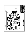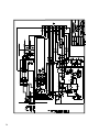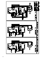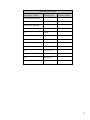
1
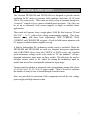
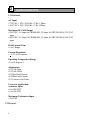
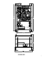
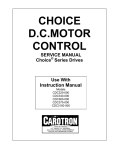
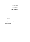
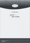
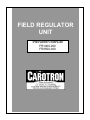
FIELD REGULATOR UNIT Instruction Manual FR1000-000 FR3500-000 Table of Contents 1. General Description .................................................................................. 3 2. Specifications ............................................................................................. 4 2.1 Electrical ............................................................................................................4 2.2 Physical ..............................................................................................................4 3. Installation ................................................................................................. 7 4. Programming & Adjustments.................................................................. 8 4.1 Programming jumpers .......................................................................................8 4.2 Adjustment Pots .................................................................................................8 4.3 DCM check points, and board test points. .........................................................9 5. Start-up Procedure.................................................................................. 10 FR1000 and FR3500 Field Supply start up procedure ..........................................10 Quick Start - Fixed Supply ....................................................................................10 Quick Start - Variable Supply................................................................................11 Quick Start - Extended Speed, Weakened Field Operation ...................................12 6. Special Circuit Functions & Modes....................................................... 14 6.1 Fault Conditions...............................................................................................14 6.2 Analog Outputs ................................................................................................14 7. Spare Parts ............................................................................................... 14 7.1 Printed Circuit Board Assemblies ...................................................................14 7.2 Power Components ..........................................................................................14 7.3 Fuses & Misc. ..................................................................................................14 8. Prints ........................................................................................................ 15 8.1 C12143 Field Regulator Control Board Assembly ………………………….15 8.2 C12141D Field Regulator Control Board Schematic ……………………….16 8.3 C12144A FR1000-000 Power Board Assembly ….………………………....17 8.4 C12142A FR1000-000 Power Board Schematic …………………………....18 8.5 C12251B FR3500-000 Power Board Assembly …………………………….19 8.6 C12250F FR3500-000 Power Board Schematic ………………………….…20 8.7 D12506BS1 FR1000, FR3500 Applications …………...……………………21 8.8 D12506BS2 FR1000, FR3500 Applications …………...……………………22 8.9 Quick Reference Table – Programming & Adjustments …..………………...23 2 1 General Description The Carotron FR1000-000 and FR3500-000 are designed to provide current regulation for DC motor or generator field windings rated from .1A-10A and 10A to 35A respectively. These units are easily set up as constant horsepower “crossover” controls to give a motor extended speed operation. Also, they can be set up as alternative field current supplies in single or multiple motor applications. These units will operate from a single-phase 50/60 Hz line between 230 and 460 VAC, + 10 %, with no line voltage programming required. They have intuitive set-up with three basic adjustments: MIN CURRENT, MAX CURRENT and CROSSOVER set point. A built-in field current ammeter with 0.1-ampere resolution further simplifies set-up. A built-in independent DC tachometer scaling circuit is included. When the FR1000-000 and FR3500-000 are used in a constant horsepower application with CAROTRON drives from the CHOICE or ELITE series, the extended speed tachometer voltage can be easily scaled to “fit” the standard 7 volt-perthousand tachometer input range on these models. This alleviates the need to calculate resistor values to be added for scaling the tachometer input for models that do not have an adjustable tachometer input range. Current control resolution is optimized with a programming jumper that selects a 2,4,6,8,10 or15, 20, 25, 30 or 35 ampere range. There’s no need to calculate the number of turns of wire to thread through a current sensor. Fuses are provided for protection of the components in both the low voltage power supply and high current section. 3 2 Specifications 2.1 Electrical AC Input • 230 VAC ± 10%, 50/60 Hz ± 2 Hz, 1 Phase • 460 VAC ± 10%, 50/60 Hz ± 2 Hz, 1Phase Maximum DC Field Output • 200 VDC, 10 Amps for FR1000-000, 35 Amps for FR3500-000 @ 230 VAC input • 400 VDC, 10 Amps for FR1000-000, 35 Amps for FR3500-000 @ 460 VAC input Field Current Trim • 6 to 1 Range Current Regulation • + 0.5% of set current Operating Temperature Range • 0 to 55 degrees C Adjustments • P1 Tach Gain • P2 Tach Offset • P3 Min Field Current • P4 Max Field Current • P5 Crossover Set Point Crossover Application: Armature Input • 0 to 240 VDC • 0 to 500 VDC Maximum Tachometer Input • 250 VDC 2.2 Physical 4 EXT CUR REF DCM CN2 CLOSE TO RUN TACH IN TACH IN TB1 TACH OUT SHIELD TACH OUT FAULT RELAY CLOSE OUTPUT TO RESET 1 SOT4 SOT2 14 LOOP J2 RESPONSE FAST SLOW SOT3 SOT1 CUR /B TP1 CONTROL MODE TP2 AUTO J3 MAN VOLTS /B P1 TACH VOLTS 250V 100V 50V J5 25V ARM VOLTS 500V J4 240V P2 TACH GAIN TACH OFFSET SW1 I5 I6 FIEL WEAKE PUSH TO ADJ MIN CURRENT I1 CN1B I3 FIELD ECONOMY I2 CONTROL POWER FU1 FU2 15 AMP MAX 15 AMP MAX ARM OVER VOLTAGE P3 P4 P5 I4 FIELD UNDER CURRENT MIN CUR MAX CUR CROSSOVER 1A KTK OR EQ TB2 1 FR1000-000 POWER BOARD ASSY C12144-000 L1 L2 230/460VAC INPUT A1 A2 240/500VDC ARM INPUT F1 F2 FIELD OUTPUT FR1000-000 5 EXT CUR REF DCM CN2 CLOSE TO RUN TACH IN TACH IN TB1 TACH OUT SHIELD TACH OUT FAULT RELAY CLOSE OUTPUT TO RESET 1 SOT3 SOT1 SOT4 SOT2 14 LOOP J2 RESPONSE FAST SLOW FLD CUR F/B TP1 CONTROL MODE AUTO J3 MAN TP2 ARM VOLTS F/B 250V 100V 50V J5 25V P2 TACH GAIN TACH OFFSET FIELD REGULATOR CONTROL BOARD ASSY C12143-000 SW1 I5 I6 FIELD WEAKENED PUSH TO ADJ MIN CURRENT CN1B I1 FIELD ECONOMY I2 CONTROL POWER I3 ARM OVER VOLTAGE P3 P4 P5 I4 FIELD UNDER CURRENT FR3500-000 6 P1 TACH VOLTS ARM VOLTS 500V J4 240V MIN CUR MAX CUR CROSSOVER 3 Installation The Field Regulator Unit should be installed in accordance with the National Electric Code and any applicable local or state codes. WIRING PRECAUTIONS: Use shielded cable for all signal wiring. Connect the shield to circuit common at the receiving circuit end only. Any relays, contactors, motor starters, solenoids, etc. located in close proximity to or on the same AC line as the Field Regulator Unit should have a transient suppression device in parallel with the coil to minimize interference with the unit. TERMINAL CONNECTIONS: TB1 Terminals 1,2 &3 External pot for field current control when in the manual mode. Note that a pot connected with the clockwise terminal at TB1-3 will increase field current as the pot setting is increased. When this pot is used to control motor speed, it should be connected in reverse so that field current will decrease as the setting is increased. Terminals 4 & 5 RUN terminals. (Closure shuts off field economy) Terminals 6 & 7 DC tachometer from motor Terminal 8 Incoming tachometer shield Terminals 9 & 10 Scaled tachometer output voltage to be used by the armature supply. Terminals 11&12 Fault reset. A closure will reset a Fault. Terminals 13&14 An internal N/O contact that closes with correct function of the unit and opens with a Fault. CN1 This connector is for the use of the DCM100-000 (Drive Circuit Monitor). This is an optional digital meter sold by Carotron to be used to monitor the various functions indicated on the schematic. L1, 2 The 230/460vac power connects here. This power is any 2 lines of the 3 lines used for the 3 phase power used on the Armature supply or drive. TB2 Terminal 1 is the positive (F1) terminal of the field output. Terminal 2 is the negative (F2) terminal of the field output. Terminal 3 is the A1 input terminal of the armature voltage. Terminal 4 is the A2 input terminal of the armature voltage (If an Armature contactor is used, these terminals must be connected to the motor side of the contactor). 7 4 Programming & Adjustments 4.1 Programming Jumpers J1 Field Current (power board) The unit has 5 ranges of current. They are 2,4,6,8,10 or 15, 20, 25, 30 & 35A. Set the jumper appropriately for the motor used. J2 Loop Response (control board) This setting is a function of the motor size. Smaller motors have less inductance and may need the FAST setting. Large motors may need the SLOW setting. The SOT terminals are provided for use in special applications. J3 Control Mode (control board) AUTO setting is used with Crossover operation. MAN is used for Manual operation with the TB1 pot. J4 Arm Volts (control board) Set this according to the armature voltage for the Crossover Mode. J5 Tach Volts (control board) Set this according to the maximum DC tachometer voltage expressed as follows: Max Voltage = Max extended RPM x (Tachometer volts per 1000 RPM rating) 1000 4.2 Adjustment Pots P1 TACH GAIN This pot sets the scaling of the tach output relative to the voltage from the tachometer on the motor. P2 TACH OFFSET This sets the output to zero with no voltage from the tachometer. P3 MIN CUR This sets the lowest level of field current (minimum current) when in the crossover mode or when the TB1 pot is at full CCW in the variable mode. P4 MAX CUR This sets the highest level of field current (maximum current) when in the crossover mode or when the TB1 pot is at full CW in the variable mode. P5 CROSSOVER This sets the armature voltage level at which the field current begins to reduce (begins field weakening). P6 FIELD CURRENT METER CALIBRATE Factory set – do not adjust. 8 4.3 DCM check points, and board test points. (The reference point for test point measurements can be circuit common at TB1- 1,7,8 or 10) TP1: TP2: Field current; 10V = 100% (100% is the J1 selected value) Armature voltage (7.7V = motor base voltage) DCM A: DCM B: DCM C: DCM D: DCM E: DCM F: DCM G: DCM I: DCM J: DCM K: DCM L: DCM M: DCM N: DCM O: DCM P: DCM R: DCM S: 12VDC +5% 5VDC +5% 15VDC +5% -15VDC +5% Field current (scaled IFB, 2.37V = 100%) Armature over voltage fault (high = true) 20VDC +7% Scaled tach output (7v/1000RPM) Field current (10V = 100%) Field undercurrent fault (high = true) Scaled tach input Current reference (10v = Max current, 0v = Min current) Scaled armature volts (7.7v = 100% armature volts) Field economy (low = true) Crossover set point -20VDC + 7% Regulation trigger voltage (regulation loop error) – sums with the phase reference saw tooth voltage to create the trigger pulses Field weakening voltage (>10 v = Max field, <0v = Min field) DCM T: 9 5 Start-up Procedure FR1000 and FR3500 Field Supply start up procedure The FR1000-000, FR3500-000 Field Regulator Unit has three programmable modes of operation. Two of the modes use field current reduction to increase motor speed, which also results in reduced output torque from the motor. 1) FIXED SUPPLY: where base speed or speed at highest rated armature voltage and field current is the highest speed required and an accurate field current is needed over the temperature range of the motor. 2) VARIABLE SUPPLY: where it is desired to extend speed by weakening the field but with manual or dancer pot control of the field. 3) EXTENDED SPEED, WEAKENED FIELD OPERATION (OR CROSSOVER OPERATION): This mode allows higher than base speed operation (with constant horsepower above base speed). The tachometer feedback is required to keep motor speed linear with respect to the speed reference. QUICK START - FIXED SUPPLY (REFER TO FIG 3 page 22) 1) Make preparations to measure the armature voltage with a DC voltmeter. 2) Have a tachometer ready to measure the motor shaft or machine speed. 3) Pre-set pots and jumpers as follows: On the FR1000-000, FR3500-000: a) J3, CONTROL MODE, jumper to MAN position b) P4, MAX FIELD CURRENT, full CCW c) P3, MIN FIELD CURRENT, full CCW d) J1, CURRENT RANGE, (on Power Board) position near base field current e) Connect a wire jumper on TB1, 2-3 f) Connect a wire jumper on TB1, 4-5 to take the place of a contact for run (to switch out of field economy) g) Other pots and jumpers not critical for initial startup On the drive or Armature voltage control: h) Place in “Armature Feedback” mode. 4) Power up the Field supply with the Armature supply off. 5) Press SW1, MIN FIELD SET, and adjust P3 to approximately 50% of desired field current. Release SW1 and adjust P4 to get rated maximum field current (on motor nameplate). 10 6) .Connect field economy contact to TB1, 4-5, power and start the drive and adjust for maximum rated armature voltage. Measure motor speed. The field current can be reduced to increase speed but will result in decreased motor torque. Adjust the armature voltage if a reduction in speed is necessary. 7) Stop the drive and place in Tachometer Feedback mode if necessary. Re-check maximum speed and adjust with the armature voltage as required. TP1 can be used to monitor the Field current (10v = 100% of J1 set value). QUICK START - VARIABLE SUPPLY (REFER TO FIG 4 page 22) 1) Make preparations to measure the armature voltage with a DC voltmeter. 2) Have a tachometer ready to measure the motor shaft or machine speed. 3) Connect a pot, between 2k and 20k ohms, on TB1- 1,2, & 3 as shown on the silkscreen. 4) Pre-set pots and jumpers as follows: On the FR1000-000, FR3500-000: a) J3, CONTROL MODE, jumper to MAN position b) P4, MAX FIELD CURRENT, full CCW c) P3, MIN FIELD CURRENT, full CCW d) J1, CURRENT RANGE, (Power board) to a position near base field current e) Connect a wire jumper on TB1, 4-5 to take the place of a contact for Run (to switch out of field economy) f) TB1 pot full CW or for maximum field current g) Other pots and jumpers not critical for initial startup On the drive or Armature voltage control: h) Place in “Armature Feedback” mode. 5) Power up the field supply with the armature supply off. 6) Adjust P4 to base, maximum, field current (on motor nameplate). 7) Start the drive and adjust to maximum rated, base speed, armature voltage. 8) While monitoring motor speed, slowly decrease the TB1, manual, pot until rated extended speed or desired maximum speed is reached. Note this field current level. 9) Stop the motor (turn off the armature supply). Press MIN FIELD SET button. Adjust P3 to the current for extended speed (step 8). Release the button. Reset P4 to base current. 10) Connect the field economy contact to TB1, 4-5. 11) Turn on the motor and confirm the range of the TB1 pot to cover the speed range of base speed to max speed. 12) TP1 can be used to monitor the field current (10v = 100% of J1 set value). 11 QUICK START - EXTENDED SPEED, WEAKENED FIELD OPERATION (REFER TO FIG 5 page 22) NOTE: If the Armature control has no 7v/1000 rpm input omit step 6 & 9. 1) Make preparations to measure the armature voltage with a DC voltmeter. 2) Have a tachometer ready to measure the motor shaft or machine speed. 3) Pre-set pots and jumpers as follows: On the FR1000-000, FR3500-000: a) J3, CONTROL MODE, jumper on the Control Board to MAN position. b) Wire jumper on TB1, 2-3. c) P4, MAX FIELD CURRENT, to full CCW. d) P5, CROSSOVER, full CW. e) P3, MIN FIELD CURRENT, full CCW. f) J1, CURRENT RANGE, (Power Board) near base field current. g) J5, TACH VOLTS, to tachometer voltage at full speed. h) J4, ARM VOLTS, to correct voltage position. k) Put a wire jumper on TB1, 4-5 to take the place of a run contact (to switch out of field economy). l) Other pots and jumpers not critical for the initial startup. On the drive or Armature voltage control: m) Place in “Armature Feedback” mode. n) TACH VOLTS jumper to 7 volts/1000RPM on the armature control. o) Temporarily adjust ACCEL and DECEL times of armature control to 15 to 20 seconds. NOTE: “Field Weakening” is a way to extend DC motor RPM above base speed. If the base field current and weakened field current are known (from the motor data) go to step 10. If the weakened field current is not known go to step 4. 4) Power up the field supply with the armature supply off. 5) Adjust P4, MAX FIELD CURRENT, to get the base field current (from the nameplate). Raise P3, MIN FIELD CURRENT, if P4 will not go to that level. NOTE: Omit steps 6 and 9 if the armature control has no 7v/1000 RPM input or if it can easily, directly scale the extended speed tachometer voltage. 6) Adjust the TACH OFFSET, pot P2, so there is 0.0 volts on the TACH OUT position TB1, 9-10) 7) Power up the armature supply and adjust to motor maximum rated armature voltage which should run the motor at base speed. Check the motor speed with a tachometer. 8) Reduce the field current with P4 (MAX FIELD CURRENT) to achieve the desired extended speed. The field current now flowing is the weakened field current. Note this current level. 12 9) Measure TB1-9-10, and adjust TACH GAIN, P1, to get 12.25VDC. 10) Stop the armature control. Press the MIN FIELD SET button and set P3, MIN FIELD CURRENT, to the weakened field current. Release the button and set P4, MAX FIELD CURRENT, to the base field current level. Re-start the armature supply and slowly increase the speed reference to make the armature voltage equal to about 92% of the base, maximum, armature volts. Decrease the P5 (CROSSOVER SET POINT) to the level where the I6, FIELD WEAKENED, light just turns on. Stop at that point. Stop the control and remove all power. Select Tach Feedback on the armature control. On the FR3500-000, put J3 in AUTO. 11) 12) 13) NOTE: Closely monitor the motor speed during the next step. If the speed is unstable go to step 15 to adjust out this instability. 14) 15) Re-apply power and start the control with the speed reference at zero. Slowly raise the speed and watch the field current and armature voltage. When the armature voltage reaches the crossover level, (92%), the field current will begin to decrease. As the speed reference is increased to maximum, the field current will decrease to the minimum level. With tachometer feedback, the speed will be proportional to the speed reference. Adjust the max speed pot on the armature control to get the speed range desired. Do not exceed the nameplate armature voltage. If the operation is stable, set-up is complete. With the speed reference fixed at an unstable point try to adjust the armature velocity and current tuning adjustments. If this is not successful, stop the motor, remove AC power from the Field Regulator and move the J2 jumper to the “SLOW” position. Restart the motor and if necessary, retry the armature velocity and current tuning adjustments. When the speed is steady go back to step 14. 13 6 Special Circuit Functions & Modes 6.1 Fault Conditions The FR1000-000, FR3500-000 Field Regulator Unit has two fault modes. One is ARMATURE OVER VOLTAGE and the other is FIELD UNDER CURRENT. ARMATURE OVER VOLTAGE has a threshold of 125% and FIELD UNDER CURRENT has a threshold of 85% (approximately 40% for fixed operating mode). They each have an LED Indicator and they combine to one contact opening. The fault contact is a N.O. contact that closes with a normal power up condition of the unit and opens with a fault. 6.2 Analog Outputs There are two terminals that output signals proportional to field current and armature voltage. The signals are measured with respect to common at terminals TB1-1, 7, 8 or 10. These terminals can be used as test points or can accept 0.110 x 0.020 quick connects to provide an external display. TP1, IFB Meter, outputs 10 VDC at 100% of the current range programmed by J1 on the Power Board. TP2, Scaled Armature Volts, outputs 7.7 VDC at 100% of the voltage range programmed by J4 on the Control Board. 7 Spare Parts 7.1 Printed Circuit Board Assemblies Power Board ............................................................................. FR1000-000: C12144 FR3500-000: C12251 Control Board .......................................................................................... C12143-000 7.2 Power Components FR1000-000 Dual diode, 31 ampere, 1400 V............................................................. PMD1028-00 Dual SCR, 25 ampere, 1400 V .............................................................. PMD1017-00 FR3500-000 Dual diode, 61 ampere, 1400 V............................................................. PMD1028-01 Dual SCR, 56 ampere, 1400 V .............................................................. PMD1026-00 7.3 Fuses & Misc FR1000-000 F1&F2, 15 ampere, 600v Buss KTK or eq……………………………..FUS1004-00 FR3500-000 F1& F2, 40 ampere, 600 V, Littelfuse type JLS40 or equivalent ...........FUS1015-00 Ribbon Cable, 16 pin, socket/socket, 9 inches long ............................... CNT1067-00 14 8 Prints Control Board Assembly Dwg. 15 16 P1 L1 230/460VAC INPUT L2 15 AMP MAX 15 AMP MAX TB2 1 FU2 FU1 CN1A 10A 8A 6A 4A 2A J1 17 A2 240/500VDC ARM INPUT A1 F2 FIELD OUTPUT F1 FR1000-000 POWER BOARD ASSY C12144-000 1A KTK OR EQ 18 19 1A FNQ OR EQ. 20 21 22 Quick Reference Table Pot/Jumper Settings Factory Preset Customer Setting 35A POWER BOARD: J1 10A OR 35A CONTROL BOARD: J2 FAST J3 MAN J4 500V J5 25V P1 MIDWAY P2 MIDWAY P3 MAX CCW P4 MAX CCW P5 MAX CW P6 DO NOT ADJ 23 3204 Rocky River Road Heath Springs, SC 29058 Phone: (803) 286-8614 Fax: (803) 286-6063 Email: [email protected] Web: www.carotron.com MAN1042-0D Issued 6-23-05