1
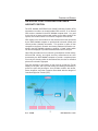
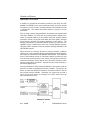
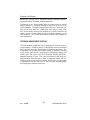
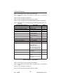
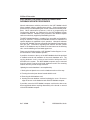
N
KGP 560 & KGP 860
General Aviation
Enhanced Ground Proximity Warning System
B
Pilot’s Guide
The information contained in this manual is for reference use only. If
any information contained herein conflicts with similar information
contained in the Airplane Flight Manual Supplement, the information in
the Airplane Flight Manual Supplement shall take precedence.
WARNING
The enclosed technical data is eligible for export under License Designation
NLR and is to be used solely by the individual/organization to whom it is
addressed. Diversion contrary to U.S. law is prohibited.
COPYRIGHT NOTICE
Copyright © 2000, 2001, 2003-2005 Honeywell International Inc.
All rights reserved.
Reproduction of this publication or any portion thereof by any means without
the express written permission of Honeywell International Inc. is prohibited.
For further information contact the Manager, Technical Publications;
Honeywell Business & General Aviation; One Technology Center; 23500
West 105th Street; Olathe, Kansas 66061. Telephone: (913) 782-0400.
TOC R5
8/9/04
2:50 PM
Page TCI
Table of Contents
KGP 560 & KGP 860
Enhanced Ground Proximity Warning System
TABLE OF CONTENTS
INTRODUCTION . . . . . . . . . . . . . . . . . . . . . . . . . . . . . . . . . . . . . . . . . . . . . . . . . . . .1
What is the GA-Enhanced Ground Proximity Warning System? . . . . . . . . . . . . . . . .2
Regulatory Standards . . . . . . . . . . . . . . . . . . . . . . . . . . . . . . . . . . . . . . . . . . . . . . . . .3
GA-EGPWS FUNCTIONS AND FEATURES . . . . . . . . . . . . . . . . . . . . . . . . . . . . . . .5
Aircraft Position . . . . . . . . . . . . . . . . . . . . . . . . . . . . . . . . . . . . . . . . . . . . . . . . . . . . .5
Aircraft Altitude . . . . . . . . . . . . . . . . . . . . . . . . . . . . . . . . . . . . . . . . . . . . . . . . . . . . . .6
Terrain, Obstacles & Runway Database . . . . . . . . . . . . . . . . . . . . . . . . . . . . . . . . . .7
Terrain Inhibit Switch . . . . . . . . . . . . . . . . . . . . . . . . . . . . . . . . . . . . . . . . . . . . . . . . .9
Terrain Awareness Display . . . . . . . . . . . . . . . . . . . . . . . . . . . . . . . . . . . . . . . . . . . .10
“Look-Ahead” Alerting and Warning . . . . . . . . . . . . . . . . . . . . . . . . . . . . . . . . . . . . .15
Runway Field Clearance Floor (RFCF) . . . . . . . . . . . . . . . . . . . . . . . . . . . . . . . . . .16
Excessive Rate of Descent Alerting and Warning . . . . . . . . . . . . . . . . . . . . . . . . . .17
Inadvertent Descent / Loss of Altitude After Take-Off . . . . . . . . . . . . . . . . . . . . . . .19
GA-EGPWS Altitude Monitoring . . . . . . . . . . . . . . . . . . . . . . . . . . . . . . . . . . . . . . . .20
Altitude Call-out . . . . . . . . . . . . . . . . . . . . . . . . . . . . . . . . . . . . . . . . . . . . . . . . . . . .20
Aircraft Configuration Alerts (Gear & Flap Alerts - KGP 860 Only) . . . . . . . . . . . . .20
Bank Angle Alert (KGP 860 Only) . . . . . . . . . . . . . . . . . . . . . . . . . . . . . . . . . . . . . .21
NORMAL PROCEDURES . . . . . . . . . . . . . . . . . . . . . . . . . . . . . . . . . . . . . . . . . . . .23
GA-EGPWS System Self-Test . . . . . . . . . . . . . . . . . . . . . . . . . . . . . . . . . . . . . . . . .23
Recommended Procedures for GA-EGPWS Warnings In Flight . . . . . . . . . . . . . . .25
Recommended Procedures for GA-EGPWS Alerts In Flight . . . . . . . . . . . . . . . . . .26
ADDITIONAL INFORMATION . . . . . . . . . . . . . . . . . . . . . . . . . . . . . . . . . . . . . . . . .27
Audio Message Priority . . . . . . . . . . . . . . . . . . . . . . . . . . . . . . . . . . . . . . . . . . . . . .27
GA-EGPWS Cockpit Lamps & Switches . . . . . . . . . . . . . . . . . . . . . . . . . . . . . . . . .29
KGP 560/860 System Limitations . . . . . . . . . . . . . . . . . . . . . . . . . . . . . . . . . . . . . . .29
KGP 560/860 Continued Airworthiness and Database Update Procedures . . . . . .30
KGP 560/860 Product Support . . . . . . . . . . . . . . . . . . . . . . . . . . . . . . . . . . . . . . . . .31
Rev 5 Jul/2004
i
KGP 560/860 Pilot's Guide
TOC R5
8/9/04
2:50 PM
Page TCII
Table of Contents
Intentionally left blank
Rev 5 Jul/2004
ii
KGP 560/860 Pilot's Guide
Introduction
INTRODUCTION
The Bendix/King KGP 560 & KGP 860 General Aviation Enhanced
Ground Proximity Warning System (GA-EGPWS) brings state-of-the-art
technology in Terrain Display, Situational Awareness, Terrain Alerting
and Warning, and Obstacle Alerting and Warning to the General
Aviation pilot. The KGP 560 & KGP 860 GA-EGPWS is an affordable,
extremely lightweight, compact and rugged computer that is easily
installed in single- and multi-engine piston aircraft as well as small turboprops and other aircraft.
Based on 30 years experience in the development and advancement of
Ground Proximity Warning Systems for Air Transport, Regional and
Commuter Airlines, Military aircraft and Corporate aviation, Honeywell
brings this vital safety technology to all segments of General Aviation.
Using our proprietary world-wide terrain database, obstacle database,
runway database, state-of-the-art GPS technology, and proven Terrain
Display with Alerting and Warning functions, the system provides the
General Aviation pilot with superior situational awareness with respect to
terrain and known obstacles. In addition, the system contains the most
advanced alerting and warning functionality to warn the pilot of danger
with respect to terrain, man-made obstacles and other primary scenarios
associated with the dangers of Controlled Flight Into Terrain (CFIT).
The KGP 560 & KGP 860 GA-EGPWS Computer
(less than 1.5 pounds, KGP 560 shown, KGP 860 similar)
Rev 5 Jul/2004
1
KGP 560/860 Pilot's Guide
Introduction
Use of a terrain display is optional, but recommended in order to
enhance full situational awareness. If a terrain display is not installed in
the system, all alerts and warnings are still present.
This Pilot’s Guide outlines the basic requirements for system operation
and recommended procedures for use of the KGP 560/860 GA-EGPWS.
This Guide does NOT supersede FAA Approved Data or FAA Flight
Manual Supplements, or FAA Required Procedures. Each pilot should
be thoroughly familiar with his or her aircraft, its systems, and FAA
and/or company requirements for that aircraft as equipped with the KGP
560/860 General Aviation Enhanced Ground Proximity Warning System.
WHAT IS THE GA-ENHANCED GROUND PROXIMITY
WARNING SYSTEM?
The Bendix/King KGP 560/860 GA-EGPWS is a small lightweight computer that can be installed in most single- and multi-engine piston aircraft,
small turboprop aircraft and other aircraft in which a Terrain Avoidance &
Warning System is applicable. Additional interface capability with the
KGP 860 allows the system to be installed in larger corporate and business aircraft.
The KGP 560/860 computer is compact and rugged, and can be
mounted in any number of orientations to meet the requirements of the
aircraft and space limitations. The computer weighs less than 1.5
pounds.
The system uses information from an existing GPS (already in the aircraft) or internal GPS receiver contained in the KGP 560/860 computer.
The only other required input is uncorrected barometric pressure from
the aircraft’s transponder or altitude reporting/encoding device. An additional input of Outside Air Temperature (OAT) is optional. See section
on Aircraft Altitude.
The system can also accept inputs from various digital air data computers, when such equipment is available on an aircraft. The terrain
database, obstacle database, runway database and alerting/warning
functionality are contained in the KGP 560/860 computer, and require no
pilot action for system operation.
Outputs generated by the system are:
* Terrain / Obstacle Display
* Voice alerts / Warnings / Call-outs
* Visual alerts / Warnings
Rev 5 Jul/2004
2
KGP 560/860 Pilot's Guide
Introduction
During normal flight operations, the system remains essentially silent,
using GPS, altitude and temperature (optional) data in combination with
its various database information to provide the pilot with a display of the
aircraft position relative to surrounding terrain and known obstacles,
thereby providing unprecedented situational awareness for the pilot.
Pilot workload in interacting with the system during normal flight is minimal.
Should the aircraft fly into danger where a conflict with terrain or a known
obstacle is imminent, the system will provide both visual and aural alerts
and warnings to the pilot. The system also provides alerts and warnings
for excessive rates of descent and inadvertent descents or altitude loss
after take-off.
The system provides an aural altitude call-out when 500 feet above
runway elevation during a landing approach, and also monitors altimeter
systems in the aircraft to provide alerts for possible altimeter malfunctions or errors.
The KGP 860 also provides low gear and flap alerting as well as an
excessive bank angle call-out, if configured
Pilot reactions to alerts and warnings differ according to weather conditions, visibility, type of warning, phase of flight and aircraft performance
considerations. Pilots should be thoroughly familiar with FAA, company,
or other approved operational procedures as required by their aircraft
and type of operation. Pilots should train to react properly to alerts and
warnings just as one would train to react to an aircraft stall, engine failure
or any other emergency situation.
REGULATORY STANDARDS
The KGP 560/860 GA-EGPWS containing Software Version -0005 or
later satisfies the requirements for Terrain Avoidance & Warning
Systems (TAWS) as defined by FAA TSO C151b, Class B & Class C,
when installed in aircraft in accordance with approved procedures. (See
KGP 560 or KGP 860 GA-EGPWS System Installation Manual,
whichever is applicable). The KGP 560/860 GA-EGPWS containing software earlier than -0005 satisfies the requirements for Terrain Avoidance
& Warning Systems (TAWS) as defined by FAA TSO C151a, Class B
when installed in aircraft in accordance with approved procedures.
NOTE: All aircraft, which are required by Federal Aviation Regulations to
have a Terrain Awareness and Warning System complying with TSO
C151b Class B, must be configured with the Class B warning and audio
configurations.
Rev 5 Jul/2004
3
KGP 560/860 Pilot's Guide
Introduction
The KGP 560/860 GA-EGPWS may also be installed in aircraft that do
not require FAA approved TAWS systems, and may be utilized with an
optional set of alerting and warning parameters that are designed especially for smaller piston aircraft and their normal flight characteristics.
The FAA has now designated these operational TAWS requirements,
under TSO C151b as the Class C curves. These “optional alerting and
warning parameters”, now Class C operations, are set into the computer
via the Configuration Module during installation, and require no pilot
interaction.
Rev 5 Jul/2004
4
KGP 560/860 Pilot's Guide
Functions and Features
GA-EGPWS FUNCTIONS AND FEATURES
AIRCRAFT POSITION
The KGP 560/860 GA-EGPWS uses Global Positioning System (GPS)
information from either an aircraft-installed GPS receiver, or an internal
GPS receiver contained in the KGP 560/860 computer itself. It is good
for the pilot to be aware of the actual position source being used by the
system, as the internal GPS is not used for navigation of the aircraft.
GPS signals arrive at an antenna on the aircraft and are then processed
by the KGP 560/860 computer to provide both horizontal (lateral) and
vertical position (altitude) information. This position in space is then
compared to the terrain, obstacle and runway database information contained in the KGP 560/860 computer to produce a “virtual” picture which
can then be displayed to provide Situational Awareness for the pilot.
Other GPS information such as true track, groundspeed, vertical velocity,
N/S and E/W velocity, and signal accuracy measurements are also
processed by the KGP 560/860 computer to provide a complete picture
of not only the aircraft position in three dimensions, but also an excellent
picture of the aircraft’s flight path.
This total package of information is then used to provide the Terrain
Display for the pilot, and to provide alerting and warning functionality to
protect the pilot and passengers from possible conflicts with terrain,
known obstacles, and other scenarios associated with the dangers of
Controlled Flight Into Terrain (CFIT).
Rev 5 Jul/2004
5
KGP 560/860 Pilot's Guide
Functions and Features
AIRCRAFT ALTITUDE
In addition to the altitude information provided by the GPS, the KGP
560/860 GA-EGPWS uses uncorrected barometric pressure altitude
information from the aircraft’s encoding altimeter, blind altitude encoder
or transponder. This altitude information allows the system to do two
main tasks.
First, by using a special “derived-altitude” developed by Honeywell called
“Geometric Altitude”, the GPS and uncorrected pressure altitude information is blended together by the system to provide accurate altitude
information, which is using the same Mean Sea Level (MSL) reference
as the terrain, obstacle and runway databases in the system. The
blending functionality of “Geometric Altitude” means it is much less susceptible to errors or malfunctions in the use of normal altimeter systems.
(The pilot is NOT required to enter an altimeter setting specifically for the
GA-EGPWS system).
Where aircraft are routinely operated in extreme weather conditions
(either hot or cold), Honeywell strongly recommends the optional temperature input be used with the KGP 560/860 GA-EGPWS. This additional
factor in the blending formula of “Geometric Altitude” provides an even
more accurate vertical position to the system, and prevents serious discrepancies between actual altitude and “Geometric Altitude” under
extreme temperature conditions, especially during rapid climbing or
descending flight profiles.
The second benefit of using “Geometric Altitude” in the system is that the
pilot will now have an independent monitor of altitude. The system can
detect an abnormal difference between “Geometric Altitude” and the
uncorrected pressure altitude. Optionally, the system can provide a
voice call-out and display a message to the pilot should such an
abnormal difference occur.
Geometric Altitude
Rev 5 Jul/2004
6
KGP 560/860 Pilot's Guide
Functions and Features
On some terrain displays, an indication of MSL or GSL altitude will
appear. This altitude is the reference altitude for the display and the terrain awareness algorithm. This reference altitude is based on internally
calculated Geometric Altitude and NOT corrected barometric altitude that
must be used when navigating within the National Airspace System.
Geometric Altitude is the height above Mean Sea Level (MSL) derived
from the GPS receiver, filtered by the vertical figure of merits from the
same GPS and complemented by short term variations in barometric altitude. It represents the aircraft's calculated true height above MSL and
serves as the reference altitude for color-coding of the terrain display and
the altitude input to the look-ahead algorithm. On some displays the
Geometric Altitude number may be labeled `MSL', `GSL' (Geodetic Sea
Level) or have no label. Exact location and display definition of this altitude is detailed in the Operating Guide and/or Flight Manual
Supplements of the display system.
Because Geometric Altitude is primarily comprised of GPS altitude, this
reference altitude will often differ from cockpit displayed corrected barometric altitude. The geometric altitude is not to be used for navigation. It is presented to provide the crew with additional situational awareness of true height above sea level upon which terrain alerting and display is based. GPS altitude is an altitude above Mean Sea Level and it
is the geodetic height above the WGS-84 ellipsoid corrected by the geoid
height in the GPS receiver itself. With Selective Availability turned off as
currently, the accuracy is usually better than 75 feet and with Selective
Availability turned on, short term accuracy is in the order of 400 feet, but
the geometric altitude should be within 100 feet.
TERRAIN, OBSTACLES & RUNWAY DATABASE
The KGP 560/860 GA-EGPWS contains a removable database card,
which is inserted into the unit through a slot in the top surface of the computer. This card contains all the terrain data, known obstacles data
(where available), and runway data used by the system. This card must
be installed in the computer for proper operation. Instructions for update
procedures and installation of the database card are discussed later in
this guide.
Terrain data is supplied from the same proprietary database used by
other Honeywell EGPWS products, and is divided into three regions
worldwide. (See the following pictures). The terrain data is divided into
grid patterns of various sizes, from areas about 1/4 nm square resolution
to areas of about 5 nm square. This allows a large area of data to be
stored in the unit, and allows high-resolution data near airports, with
lower resolution data where terrain is not a factor and airports are
sparse.
Rev 5 Jul/2004
7
KGP 560/860 Pilot's Guide
Functions and Features
75°
75°
60°
60°
45°
45°
30°
30°
15°
15°
0°
0°
15°
15°
30°
30°
45°
45°
60°
60°
165°150° 135° 120°105° 90° 75° 60° 45° 30° 15° 0° 15° 30° 45° 60° 75° 90° 105°120°135°150° 165°180°
Regional Database: Americas (shaded areas)
75°
75°
60°
60°
45°
45°
30°
30°
15°
15°
0°
0°
15°
15°
30°
30°
45°
45°
60°
60°
165°150° 135° 120°105° 90° 75° 60° 45° 30° 15° 0° 15° 30° 45° 60° 75° 90° 105°120°135°150° 165°180°
Regional Database: Atlantic (shaded areas)
Rev 5 Jul/2004
8
KGP 560/860 Pilot's Guide
Functions and Features
75°
75°
60°
60°
45°
45°
30°
30°
15°
15°
0°
0°
15°
15°
30°
30°
45°
45°
60°
60°
165°150° 135° 120°105° 90° 75° 60° 45° 30° 15° 0° 15° 30° 45° 60° 75° 90° 105° 120°135° 150° 165°180°
Regional Database: Pacific (shaded areas)
Data for known obstacles such as towers, buildings, antennas, etc. is
contained on the same database card as the terrain and airport data.
Presently, there are some 100,000-plus obstacles in the database. As
more information becomes available, Honeywell plans to expand the
obstacle coverage. The current obstacle coverage map can be accessed
at the Internet website: http:\\www.egpws.com.
Obstacles in the database are those known obstacles more than 100
feet AGL, so obstacles of lower height will not produce GA-EGPWS
“Obstacle” alerts or warnings. However, terrain elevations are “rounded”
up to the next 100 feet, so alerting and warning protection is generally
available for known obstacles that are less than 100 feet AGL.
Runway database information in the KGP 560/860 computer contains all
known runways that are 2000 feet in length or longer. This runway data
is used to adjust the alerting and warning functions of the system so as
to provide a dynamic system that is essentially free of nuisance or
unwanted warnings. A list of runways in the database can be accessed
at the Internet website: http:\\www.egpws.com. A notation of the most
recent database version available can also be found there.
TERRAIN INHIBIT SWITCH
The KGP 560/860 GA-EGPWS requires the installation of a "Terrain
Inhibit" switch as part of the system installation. When engaged by the
pilot, this switch will inhibit all visual and aural alerts and warnings associated with the GA-EGPWS. Also, an external annunciator lamp is illumi-
Rev 7 Oct/2005
9
KGP 560/860 Pilot's Guide
Functions and Features
nated and a message will be displayed indicating “Warnings Inhibited”.
The terrain display, if installed, remains operational.
The purpose of the "Terrain Inhibit" switch is to allow aircraft to operate
without nuisance or unwanted warnings at airports that are not in the
system database. Examples might be private airports or those with runways shorter than 2000 feet. Additionally, there may be some "VFRonly" airports where unique terrain features are in close proximity to the
runway, and the "Terrain Inhibit" may be used when operating in good
VFR conditions. The "Terrain Inhibit" switch should be NOT engaged for
normal operations.
TERRAIN AWARENESS DISPLAY
The KGP 560/860 GA-EGPWS can be interfaced to numerous types of
cockpit displays. Graphical display of GA-EGPWS terrain and obstacle
data is the most important enhancement to Situational Awareness. This
is especially true for lower performance aircraft. In addition to showing
terrain ahead of the aircraft, (depending on configuration settings and
display types) the system can show Geometric Altitude (MSL/GSL),
Magnetic Heading or Track. The color and intensity of the terrain displayed instantly alerts the pilot to areas of dangerous terrain and conversely to areas of less precipitous terrain. Range of the Terrain Display
is selectable by the pilot from 1 nm to 320 nm, again, depending upon
the display type installed in the aircraft.
Rev 5 Jul/2004
10
KGP 560/860 Pilot's Guide
Functions and Features
The following figure shows the Terrain Display color patterns when the
aircraft is at lower altitudes, with terrain near or above the aircraft altitude
for the display range selected by the pilot.
Rev 5 Jul/2004
11
KGP 560/860 Pilot's Guide
Functions and Features
The following figure shows the Terrain Display color patterns when the
aircraft is at higher altitudes, where terrain is a least 250 feet below the
aircraft altitude for the display range selected by the pilot.
The system will adjust colors on the Terrain Display automatically as the
aircraft altitude changes. The Terrain Display also transitions between
the lower altitude “relative” display and the higher altitude “peaks” display
automatically, so no pilot action is required for system operation.
Depending upon display type aircraft interface capabilities, the Terrain
Display can show various presentations of the terrain around and in front
of the aircraft, i.e. a “rose” or 360° compass view, a 1/3 - 2/3 360° view,
90° or 120° “arc” views with or without a vertical profile.
Rev 5 Jul/2004
12
KGP 560/860 Pilot's Guide
Functions and Features
Installations without a heading input into the KGP 560/860 will either
have a NORTH oriented or BLANK display when on the ground.
Depending upon configuration, the display will automatically transition to
a TRACK UP (MAG XXX TRK) orientation upon reaching a configurable
airspeed (typically 10 to 45 kts GPS ground speed). Once the display
has transitioned to the TRACK UP display, the depiction of terrain is oriented to the current GPS track of the aircraft. The display will continue in
this TRACK UP mode until transition below a configurable GPS speed
when it will automatically transition back to either the NORTH UP or
BLANK display. The BLANK display annunciates that the display is currently unavailable (DISPLAY UNAVAIL).
Installations with a heading input into the KGP 560/860 will present a terrain depiction oriented to the current heading of the aircraft (HEADING
UP). These installations will not transition between different orientations
of the display and will typically present the current heading as `MAG XXX
HDG'.
The most important function of the system is to provide the pilot with
easily interpreted information about terrain/obstacles relative to the aircraft, and thus increase the pilot’s Situational Awareness. In brief, when
using the Terrain Display during flight, the normal presentation of green,
yellow and red colors indicate:
The following chart outlines all the various colors used by the KGP
560/860 Terrain Display and their functions in providing Situational
Awareness to the pilot. Some display types may not support all colors
listed, or may display colors in slightly different densities than those
listed, but the system is designed to present the most appropriate Terrain
Display capable on the various display types which are usable by the
system.
Rev 5 Jul/2004
13
KGP 560/860 Pilot's Guide
Functions and Features
NOTE: Green colors indicating terrain/obstacles below the aircraft are
NOT shown when the aircraft is on the ground, to reduce display clutter
and to show only terrain that is significantly higher than the aircraft in the
departure area. Green colors will appear when the aircraft has climbed
approximately 500 to 800 feet above the elevation of the runway.
The following pictures show two examples of the Terrain Display.
Geometric Altitude
Displayed as MSL or GSL
Display Orientation
Here Magnetic Heading is
up and at 150°.
Range Rings
Outer ring is selected
range, inner ring is half
the selected range. Here
outer ring is 20nm and the
inner ring is 10nm.
Display Range
Nautical Miles
Peaks Elevation
Maximum elevation
displayed over minimum
elevation. Here maximum
elevation is 14,300ft. and
minimum is 10,000ft.
GA-EGPWS Terrain Display at 12,000 feet approaching Aspen, CO
Rev 5 Jul/2004
14
KGP 560/860 Pilot's Guide
Functions and Features
Geometric Altitude
Displayed as MSL or GSL
Display Orientation
Here Magnetic Track is
up and at 160°.
Range Rings
Outer ring is selected
range, inner ring is half
the selected range. Here
outer ring is 40nm and the
inner ring is 20nm.
Display Range
Nautical Miles
Peaks Elevation
Maximum elevation is
displayed over minimum
elevation. Here maximum
elevation is 6,000ft. and
minimum is 3,000ft.
GA-EGPWS “Peaks” Terrain Display at 12,000 feet near Seattle, WA
“LOOK-AHEAD” ALERTING AND WARNING
Using aircraft position, altitude and flight path information, the system
provides an envelope of protection for the aircraft that is independent
from the Terrain Awareness Display. This “Look-Ahead” function compares the aircraft flight path to terrain and obstacle database information,
and distance to known runways.
The following illustration is a general representation of the “Look-Ahead”
functionality.
Rev 5 Jul/2004
15
KGP 560/860 Pilot's Guide
Functions and Features
When the “Look-Ahead” function detects a terrain or obstacle threat
approximately one minute ahead of the aircraft, the voice alert “Caution
Terrain, Caution Terrain” (or “Caution Obstacle, Caution Obstacle”) is
given, and a bright, solid yellow “threat area” is shown on the Terrain
Display. Should the aircraft flight path continue toward the threat area,
the alert message will repeat approximately every 7 seconds.
If the aircraft flight path approaches to within approximately 30 seconds
of a threat area, the voice message “Terrain Ahead” (or “Obstacle
Ahead”) or optionally “Terrain Terrain, Pull Up” (or “Obstacle-Obstacle,
Pull Up”) will be given continuously and the threat area on the Terrain
Display will be shown in a bright, solid red color.
In either case, when the pilot reacts and changes the aircraft flight path
to one that will safely avoid the detected threat area, the voice alerts will
cease and the threat area(s) shown on the Terrain Display will be
removed.
RUNWAY FIELD CLEARANCE FLOOR (RFCF)
The KGP 560/860 GA-EGPWS provides additional alerting protection for
situations where aircraft descend to an altitude that is too low considering the aircraft’s distance from a known runway. This is called the
Runway Field Clearance Floor (RFCF).
NOTE: This alert function is ONLY active when the aircraft is within 5 nm
of a known runway in the system database.
Using the aircraft distance to a known runway and Geometric Altitude,
the system establishes a “floor” of protection below the aircraft.
Penetration of this floor will cause the yellow caution alert annunciator
lamp to illuminate, and the voice alert “Too Low, Too Low” to be heard.
If aircraft altitude continues to descend, the voice alert will be heard
again, and at an increasing frequency.
When the pilot reacts to the alert and climbs back above the RFCF for
the current distance from the known runway, the annunciator lamp will
extinguish and the voice alerts will cease.
The following figure is a graphical representation of the Runway Field
Clearance Floor in both the “TSO” and “optional alerting and warning
parameters outside the TSO” configurations.
Rev 5 Jul/2004
16
KGP 560/860 Pilot's Guide
Functions and Features
Runway Field Clearance Floor (RFCF)
EXCESSIVE RATE OF DESCENT ALERTING AND
WARNING
The KGP 560/860 GA-EGPWS uses both GPS Vertical Velocity and
pressure altitude to compute vertical velocity information when the aircraft does not provide specific air data for this purpose. In either case,
when the aircraft is descending toward terrain at a high rate for its relative altitude above terrain, the system will provide alerting and warning to
the pilot. This function is always active.
Rev 5 Jul/2004
17
KGP 560/860 Pilot's Guide
Functions and Features
The following graph represents the envelope of protection provided for
Excessive Rate of Descent scenarios:
Excessive Descent Rate
Initially, the voice alert “Sink Rate” will be heard, and the yellow caution
alert annunciator lamp will illuminate. If the aircraft continues in the high
rate of descent, the “Sink Rate-Sink Rate” voice alert will be repeated at
an increasing frequency.
Should the aircraft penetrate the warning boundary, the voice alert “Pull
Up” will be heard continuously and the red warning annunciator lamp will
illuminate.
In both cases, as the pilot reacts to decrease the high rate of descent
and the aircraft flight path exits the alerting/warning envelope, the annunciator lamp will extinguish and the voice alerts will cease.
Sometimes, the alerting and warning functionality for excessive rate of
descent may be overridden by the terrain “Look-Ahead” functionality.
This is normal as the “Look-Ahead” function has a higher priority in the
system alerting/warning logic. (See the Alerting/Warning Priority chart
later in this guide.)
Rev 5 Jul/2004
18
KGP 560/860 Pilot's Guide
Functions and Features
INADVERTENT DESCENT / LOSS OF ALTITUDE AFTER
TAKE-OFF
The KGP 560/860 GA-EGPWS uses known runway position and elevation information to monitor altitude during take-off and initial climb. This
function is active until the aircraft reaches an altitude of approximately
700 feet above the runway elevation used for take-off.
Should the aircraft experience an inadvertent descent or loss of altitude
after take-off, the system will illuminate the yellow caution annunciator
lamp and provide “Don’t Sink-Don’t Sink” voice alerts to the pilot. The
voice alerts will be repeated with increasing frequency.
The following graph shows this alerting envelope:
Descent After Takeoff
As the pilot adjusts the flight path of the aircraft and a positive rate of
climb is re-established, the voice alert “Don’t Sink” will cease and the
yellow caution annunciator lamp will extinguish.
NOTE: It is important for the pilot not to over-react to this situation. While
it is important to react quickly and positively to re-establish a positive rate
of climb, the pilot should remember that in the take-off / initial climb segment, the margin above stall speed for many aircraft is fairly small, and
thus must be respected.
Rev 5 Jul/2004
19
KGP 560/860 Pilot's Guide
Functions and Features
GA-EGPWS ALTITUDE MONITORING
The KGP 560/860 GA-EGPWS monitors the various altitude and temperature (if used) inputs that it receives during flight for the computation of
Geometric Altitude. If there is an abnormal difference detected among
these altitude values, the system can provide visual and voice alerts to
the pilot.
Normal differences that are the result of non-ISA temperature conditions
or are due to high or low-pressure systems will not normally activate the
altitude monitor. Large errors due to faulty equipment or malfunctioning
pitot-static systems will normally be detected by the monitor.
When an abnormal altitude discrepancy is detected by the system, there
will be a single voice call-out of “Check Altitude”. There will also be the
text message Chk Alt shown on the Terrain Display as long as the condition that triggered the alert persists.
The pilot should check all aircraft altimeters to ensure that the correct
altimeter setting is set, that altimeter systems cross-check and that the
pilot’s altimeter is not stuck and indicating an erroneous altitude.
ALTITUDE CALL-OUT
The KGP 560/860 GA-EGPWS provides an altitude call-out for the pilot,
to indicate a position approximately 500 feet above the elevation of the
runway being approached. When the aircraft is within 5 nm of a known
runway, the altitude call-out function is active, and is then triggered when
Geometric Altitude shows the aircraft 500 feet above the known runway
elevation (from the system database). Example: “Five-Hundred Above”
for installations using the optional alerting and warning parameters outside the TSO and “Five-Hundred” for TSO installations.
This call-out is not accompanied by any annunciator lamp indications
and will occur only once per approach. The Altitude Call-out is reset
when the aircraft climbs more than 700 feet above the runway elevation.
AIRCRAFT CONFIGURATION ALERTS (GEAR & FLAP
ALERTS - KGP 860 ONLY)
The KGP 860 will provide aircraft configuration alerts to notify the pilot of
Gear Up and Flaps Up conditions when close to the ground. These
alerts are functions that may be selected during installation of the KGP
860. These functions add protection for the aircraft when either gear or
Rev 5 Jul/2004
20
KGP 560/860 Pilot's Guide
Functions and Features
flaps are not in landing configuration. When the aircraft passes below
300 feet with flaps down, and the gear is up, a Gear Up aural “Caution
Gear” is given. When the aircraft passes below 300 feet with the gear
down, and the flaps are up, than an aural “Caution Flaps” is given.
When both gear and flaps are in the up position when the aircraft passes
below 300 feet, an aural “Caution Gear, Caution Flaps” will be given.
The following illustrates the Alert Area.
Gear and Flaps Alert Envelope
BANK ANGLE ALERT (KGP 860 ONLY)
The KGP 860 will provide excessive Bank Angle alerting (when configured during installation). The bank angle feature provides protection for
over-banking during maneuvering on approach or climb-out and while at
altitude. In addition, it protects against wing or engine strikes close to the
runway.
The aural call-out “Bank Angle, Bank Angle” is given when the aircraft
exceeds the roll angle as shown in the following illustration. Follow-on
aural messages are given when the aircraft roll angle increases an additional 20% from the previous alert.
The bank angle call-out is based on the aircraft’s roll angle versus
Computed Terrain Clearance. Bank Angle alerting for the KGP 860 is
shown in the following figure. The Bank Angle alert is triggered when the
aircraft banks greater than 40 degrees from 50 to 150 feet AGL The
alert value limit then varies linearly form 40 degrees at 150 feet AGL to
where the roll angle limit is 50 degrees at 1600 feet AGL and above.
Rev 5 Jul/2004
21
KGP 560/860 Pilot's Guide
Functions and Features
Excessive Bank Angle Alert Envelope
Rev 5 Jul/2004
22
KGP 560/860 Pilot's Guide
Normal Procedures
NORMAL PROCEDURES
GA-EGPWS SYSTEM SELF-TEST
Prior to flight, the system should be tested for proper operation.
Normally, this is done by the pilot during the BEFORE TAKE-OFF check.
All aircraft power and systems should be up and running, and the GAEGPWS “Not Available” annunciator lamp should be off.
NOTE: Because the system requires GPS information to operate, it may
be several minutes after power-up before the aircraft GPS system supplies accurate information to the KGP 560/860. If the internal GPS card
is used to supply position information, it may take additional time for
satellite acquisition depending upon the frequency of use of the system.
The internal GPS card requires a current almanac to locate GPS satellite
positions. This almanac can take several minutes to load. When an
accurate GPS position is acquired and the rest of the GA-EGPWS
system is available, the “NOT AVAILABLE” lamp will extinguish.
To perform a normal KGP 560/860 GA-EGPWS Self-Test:
• Press the Self-Test switch. When a Self-Test is initiated, the GAEGPWS first checks for any configuration (installation or database)
errors. If any are detected, it is audibly enunciated and the test is terminated. If none are detected, the test continues through a sequence
resulting in turning on and off all system annunciators, enunciating
specific audio messages, and if enabled, displaying a video test pattern on the terrain display. Any functions determined inoperative are
also enunciated. The Self-Test terminates automatically at its conclusion.
The following is a description of the expected results of a typical level
1 Self-Test. Actual annunciation nomenclature and sequence may
differ depending on the installation.
• Observe that the amber “Not Available” and red “Warning” annunciator lamps associated with the system illuminate.
• Observe that the voice callout “EGPWS SYSTEM, OK” is heard.
• Observe that the red “Warning” annunciator lamp extinguishes, and
the amber “Caution” annunciator lamp illuminates.
• Observe that the GA-EGPWS Terrain Display shows the Test
Pattern.
• Observe that the Terrain Display Test Pattern is removed.
• Observe that the amber “Caution” and amber “Not Available” annunciator lamps associated with the system extinguish.
Rev 6 Jan/2005
23
KGP 560/860 Pilot's Guide
Normal Procedures
Pressing the Self-Test switch as the Level One Self-Test is completed
will initiate Level Two of the internal test capability. Level Two provides
information about any faults the system may be detecting. Normally, this
will not be necessary. If a normal Self-Test is unsuccessful, a Level Two
test is automatically initiated by the system.
Further Self-Test levels may be accessed after Level Two by following
instructions to “Press to Continue” at the end of Level Two and so on.
These further levels provide information about the installation configuration, part number, and software / database versions, etc. All levels of
Self-Test may be performed on the ground, but only Self-Test Level One
and Two are accessible during flight. If the “Not Available” annunciator
lamp illuminates during flight, a Self-Test will indicate the reason.
KGP 560/860 GA-EGPWS Self-Test: Level 1 Messages
KGP 560/860 GA-EGPWS Self-Test: Level 2 Messages
NOTE: This Level 2 list contains the most commonly heard messages.
Other messages may be given, depending upon installation / equipment
types. Messages may be heard in various combinations.
Rev 6 Jan/2005
24
KGP 560/860 Pilot's Guide
Normal Procedures
RECOMMENDED PROCEDURES FOR GA-EGPWS
WARNINGS IN FLIGHT
“PULL UP”
If in Instrument conditions or at night where visual judgement of
the situation is not assured:
1. Level wings and simultaneously pitch up at a rate of 2 to 3 degrees
per second to the aircraft’s BEST ANGLE of CLIMB attitude and
speed. (RESPECT AIRCRAFT STALL CONDITION).
2. Apply Maximum Power.
3. Continue maximum climb until all visual and aural warnings cease.
4. Advise Air Traffic Control as necessary.
If in Visual conditions during the day:
1. Evaluate aircraft flight path with respect to terrain.
2. Take corrective action as necessary to recover safe terrain clearance.
3. Advise Air Traffic Control as necessary.
Rev 5 Jul/2004
25
KGP 560/860 Pilot's Guide
Normal Procedures
RECOMMENDED PROCEDURES FOR GA-EGPWS
ALERTS IN FLIGHT
“Terrain Ahead”
or
“Obstacle Ahead”
“Caution Terrain”
or
“Caution Obstacle”
“Too Low”
or
“Too Low Terrain”
“Check Altitude”
Condition: Aircraft flight path is in conflict with terrain/obstacle.
Action:
Take IMMEDIATE action to adjust flight path away from
threat until alert/warning ceases.
Condition: Aircraft flight path is in conflict with terrain/obstacle.
Action:
Adjust flight path as required away from threat until
alert/warning ceases.
Condition: Insufficient terrain clearance for phase of flight.
Action:
Adjust flight path to recover safe terrain clearance until
alert ceases.
Condition: Abnormal difference between GPS, Geometric and/or
pressure altitude information in GA-EGPWS.
Action:
“Don’t Sink”
“Sinkrate”
“500 Above”
or
“500”
“Too Low Gear”
or
“Too Low Flaps”
“Bank Angle”
Check all available aircraft altitude information. Ensure
correct altimeter setting, altimeters cross-check and are
not stuck.
Condition: Aircraft is loosing altitude during take-off climb.
Action:
Re-establish positive rate of climb.
Condition: Rate of descent is excessive for current height above
terrain.
Action:
Reduce rate of descent.
Condition: Aircraft is approximately 500 feet above nearest known
runway (within 5 nm).
Action:
Assure aircraft is in position for normal landing.
Condition: Aircraft configuration of Gear or Flap position is not
consistent with altitude above terrain.
Action:
Deploy Gear or Flaps consistent with approach to
landing.
Condition: Aircraft roll angle is greater than 40 degrees to 50
degrees depending upon altitude.
Action:
Rev 5 Jul/2004
Ensure proper terrain clearance for excessive bank
(roll) conditions.
26
KGP 560/860 Pilot's Guide
Additional Information
ADDITIONAL INFORMATION
AUDIO MESSAGE PRIORITY
Only ONE message is produced at any one time.
The highest priority voice message takes precedence, and may IMMEDIATELY interrupt any lower priority message as shown in the table below.
If the aircraft is in a situation that meets more than one condition for an
alert or warning at the same time, the higher priority message will be
heard until that condition is resolved. If the lower priority condition is still
in effect at that time, the lower priority voice message will be heard.
The following tables show the voice output that is activated for each callout, alert and warning condition. The messages are arranged from
highest priority at the top, to lowest priority at the bottom of the tables.
ALERT/WARNING CONDITION
PULL UP
TERRAIN AWARENESS PREFACE
TERRAIN AWARENESS WARNING
OBSTACLE AWARENESS PREFACE
OBSTACLE AWARENESS WARNING
TERRAIN AWARENESS CAUTION
OBSTACLE AWARENESS CAUTION
TOO LOW GEAR & FLAPS
TOO LOW GEAR
TOO LOW FLAPS
RFCF TOO LOW TERRAIN
ABOVE FIELD CALLOUT
SINKRATE
DON’T SINK
ALTITUDE MONITOR CALLOUT
BANK ANGLE
AUDIO MENU
PULL UP
TERRAIN TERRAIN or
TERRAIN AHEAD
PULL UP
OBSTACLE OBSTACLE or
OBSTACLE AHEAD
PULL UP
CAUTION TERRAIN (Pause)
CAUTION TERRAIN
CAUTION OBSTACLE (Pause)
CAUTION OBSTACLE
CAUTION GEAR CAUTION
FLAPS
CAUTION GEAR
CAUTION FLAPS
TOO LOW TERRAIN
500
SINKRATE
Note: The basic warning is
“SINKRATE (Pause)
SINKRATE”. However, if the
Mode 1 Pullup curve is violated,
only a single “SINKRATE” may
occur prior to the pull up voice.
DON’T SINK (Pause)
DON’T SINK
CHECK ALTITUDE
BANK ANGLE (Pause) BANK
ANGLE
NOTES
1
1, 2
1, 3
1, 2
1, 3
4
4
6
6
6
5
6
BANK ANGLE BANK ANGLE (at
low altitude)
Basic & Alternate Class B & Class C - Voice Menu
Rev 5 Jul/2004
27
KGP 560/860 Pilot's Guide
Additional Information
Note 1: These are the only voices that can interrupt.
Note 2: The preface voices will always be given prior to the warning
voice.
Note 3: Voice message is continuous.
Note 4: Voice message will repeat every 10 seconds.
Note 5: Voice message may be disabled depending upon configuration.
Note 6: KGP 860 only, messages may be disabled depending upon configuration.
ALERT/WARNING CONDITION
PULL UP
TERRAIN AWARENESS PREFACE
TERRAIN AWARENESS WARNING
OBSTACLE AWARENESS PREFACE
OBSTACLE AWARENESS WARNING
TERRAIN AWARENESS CAUTION
OBSTACLE AWARENESS CAUTION
TOO LOW GEAR & FLAPS
TOO LOW GEAR
TOO LOW FLAPS
RFCF TOO LOW TERRAIN
ABOVE FIELD CALLOUT
SINKRATE
DON’T SINK
ALTITUDE MONITOR CALLOUT
BANK ANGLE
AUDIO MENU
PULL UP
TERRAIN AHEAD
TERRAIN AHEAD
OBSTACLE AHEAD
OBSTACLE AHEAD
CAUTION TERRAIN (Pause)
CAUTION TERRAIN
CAUTION OBSTACLE (Pause)
CAUTION OBSTACLE
CAUTION GEAR CAUTION
FLAPS
CAUTION GEAR
CAUTION FLAPS
TOO LOW TERRAIN
500 ABOVE
SINKRATE
Note: The basic warning is
“SINKRATE (Pause)
SINKRATE”. However, if the
Mode 1 Pullup curve is violated,
only a single “SINKRATE” may
occur prior to the pull up voice.
DON’T SINK (Pause)
DON’T SINK
CHECK ALTITUDE
BANK ANGLE (Pause) BANK
ANGLE
NOTES
1
1, 2
1, 3
1, 2
1, 3
4
4
6
6
6
5
6
BANK ANGLE BANK ANGLE (at
low altitude)
General Aviation - Voice Menu
Note 1: These are the only voices that can interrupt.
Note 2: The preface voices will always be given prior to the warning
voice.
Note 3: Voice message is continuous.
Note 4: Voice message will repeat every 10 seconds.
Rev 5 Jul/2004
28
KGP 560/860 Pilot's Guide
Additional Information
Note 5: Voice message may be disabled depending upon configuration.
Note 6: KGP 860 only, messages may be disabled depending upon configuration.
GA-EGPWS COCKPIT LAMPS & SWITCHES
A representative sample of a possible annunciator and switch installation
is pictured below. Other configurations are at the discretion of the
installer and operational requirements of the aircraft.
EGPWS
ı
TEST
WARN
ALERT INHIBIT
CAUT
NOT
AVAIL
Typical Annunciator
KGP 560/860 SYSTEM LIMITATIONS
* The GA-EGPWS is a Situational Awareness tool, and an alerting and
warning device. It is not to be used for navigation of the aircraft.
* The KGP 560/860 must have an operating source of GPS information,
with enough satellites in view to provide GPS data within the accuracy
requirements of the system.
* Without the optional Outside Air Temperature (OAT) input for corrections, “Geometric Altitude” may have errors during rapid climbs or
descents in non-ISA conditions. This may affect alerting/warning times
and proper altitude reference on the Terrain Display.
* The Terrain, Obstacle and Runway database information is not allinclusive.
* The GA-EGPWS “Look-Ahead” alerting and warning, and Runway
Field Clearance Floor (RFCF) functions are gradually “de-sensitized”
as an aircraft nears a known runway. Aircraft operating in close proximity to known runways may experience very short or no advance
warnings with respect to terrain or obstacles in this area. (See sections
on GA-EPWS “Look-Ahead” and RFCF).
Rev 5 Jul/2004
29
KGP 560/860 Pilot's Guide
Additional Information
KGP 560/860 CONTINUED AIRWORTHINESS AND
DATABASE UPDATE PROCEDURES
Normal maintenance activities performed on the KGP 560/860 should
follow standard industry maintenance practices. System maintenance
practices may included updating the Terrain, Obstacle and Runway database. Other maintenance practices, such as re-programming the
Configuration Module, are addressed in the KGP 560/860 System
Installation Manual. Database load procedures and database update
cards are exclusively supplied by Bendix/King Avionics.
The KGP 560/860 database is contained in a removable card installed in
the top of each unit. It is up the KGP 560/860 customer to determine if a
specific database is applicable to their operation. Honeywell estimates
that the KGP 560/860 customer will update their database approximately
once per year. Information regarding new releases and the content
details of the database may be obtained via the internet at the following
sites: www.bendixking.com and www.egpws.com.
Please see the following section, KGP 560/860 Product Support, for contact information to order database updates.
If possible, clearance to the top of the KGP 560/860 should be provided
to facilitate removal and installation of the terrain database card. The
terrain database card is removed and installed with power NOT
APPLIED to the system. The KGP 560/860 computer may be removed
from the aircraft to extract and install database cards if the mounting
location does not provide enough clearance.
Updating the terrain database is accomplished by:
1. Moving the soft plastic cover over the database card out of the way.
2. Pressing the card ejector button located within the unit.
3. Removing the old database card.
4. Inserting the new database card and replacing the cover. Be sure to
align the arrows on the database card and KGP 560/860 computer.
If possible, mount the KGP 560/860 computer such that the above can
be accomplished without requiring disassembly of the aircraft or removal
of the KGP 560/860 computer.
Rev 5 Jul/2004
30
KGP 560/860 Pilot's Guide
Additional Information
KGP 560/860 PRODUCT SUPPORT
Customer Support:
1-800-712-0400
To order database updates, contact Navigation Services at the following
numbers:
1-800-247-0230 if calling from within the United States or Canada
(913) 712-3145 if calling from outside the United States or Canada
(913) 712-3904 FAX
e-mail: [email protected]
Database updates may also be ordered on-line by visiting
www.gpsdatabase.com
Note: If ordering a database card for the KGP 560, the serial number of
the unit must be given at the time of ordering to ensure getting the proper
type of card.
Rev 5 Jul/2004
31
KGP 560/860 Pilot's Guide
Additional Information
Intentionally left blank
Rev 5 Jul/2004
32
KGP 560/860 Pilot's Guide
Honeywell International Inc.
One Technology Center
23500 West 105th Street
Olathe, KS 66061
Telephone (913) 712-0400
FAX 913-712-1302
Copyright © 2000, 2001, 2003-2005 Honeywell International Inc.
All rights reserved.
006-18254-0001
Revision 7 Oct/2005
N