1
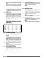
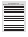
Contents
Design principles & operating sequence
1.1
1.2
1.3
1.4
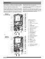
Principle components
Mode of operation (at rest)
Mode of operation
Safety devices
Technical data
2.1
2.2
2.3
2.4
2.5
2.6
2.7
2.8
2.8A
2.8B
2.9
2.10
2.11
Central heating
Gas pressures
Expansion vessel
Dimensions
Clearances
Connections
Electrical
Flue details (concentric)
Flue details (twin pipes)
Flue details (80/125)
Efficiency
Emissions
Pump duty
General requirements (UK)
3.1
3.2
3.3
3.4
3.5
3.6
3.7
3.8
3.9
3.10
Related documents
Location of appliance
Gas supply
Flue system
Air supply
Water circulation
Electrical supply
Mounting on a combustible surface
Timber framed buildings
Inhibitors
General requirements (EIRE)
3A.1 Related documents
3A.2 Location of appliance
3A.3 Gas supply
3A.4 Flue system
3A.5 Air supply
3A.6 Water circulation
3A.7 Electrical supply
3A.8 Mounting on a combustible surface
3A.9 Timber framed buildings
3A.10 Inhibitors
3A.11 Declaration of conformity
Installation
4.1
4.2
4.3
4.4
4.5
4.6
4.7
Delivery
Contents
Unpacking
Preparation for mounting the appliance
Fitting the flue
Connecting the gas & water
Electrical connections
Commissioning
5.1
5.2
5.3
5.4
5.5
5.6
5.7
5.8
5.9
5.10
5.11
5.12
5.13
Gas supply installation
The heating system
Initial filling of the system
Initial flushing of the system
Pre-operation checks
Initial lighting
Checking gas pressure & combustion analysis
Final flushing of the heating system
Setting the boiler operating temperature
Setting the system design pressure
Regulating the central heating system
Final checks
Instructing the user
Servicing
6.1
6.2
6.3
6.4
6.5
6.6
6.7
General
Routine annual servicing
Replacement of components
Component removal procedure
Pump assembly
Safety valve
Lower automatic air release valves
Page
3
3
3
3
Page
4
4
4
4
4
4
4
4
4
4
4
4
5
Page
6
6
6
6
6
6
7
7
7
7
Page
8
8
8
8
8
8
9
9
9
9
9
Page
10
10
10
10
10
14
14
Page
16
16
16
16
16
16
16
17
17
17
17
17
17
Page
18
18
18
18
18
18
19
6.8
6.9
6.10
6.11
6.12
6.13
6.14
6.15
6.16
6.17
6.18
6.19
6.20
Water pressure switch
Primary thermistor
Return thermistor
Printed circuit board
Gas valve
Electrodes and condense sensor
Flue fan & mixer
Burner
Main heat exchanger
Automatic by-pass
Expansion vessel
Condense trap removal
Flue collector removal
Checks, adjustments and fault finding
7.1
7.2
7.3
7.4
7.5
7.6
7.7
7.8
7.9
7.10
7.11
7.12
Checking appliance operation
Appliance modes of operation
Appliance fan speed
Checking the CO2 & adjusting the valve
Combustion analysis test
Checking the expansion vessel
External faults
Electrical checks
Fault finding
Component values & characteristics
Boiler configuration
Final fault codes
Wiring diagrams
8.1
8.2
8.3
8.4
External wiring
Typical control applications
Other devices
Vokera twin-channel programmer
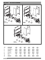
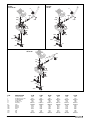
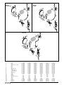
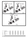
Exploded diagrams
9.1
9.2
9.3
9.4
9.5
Table
Table
Table
Table
Table
1
2
3
4
5
L.P.G. instructions
10.1
10.2
10.3
10.4
10.5
10.6
10.7
Related documents
Technical data
Converting the appliance gas type
Gas supply
Gas supply installation
Adjusting the gas valve
Appliance fan speed
Benchmark
19
19
19
19
19
20
20
20
20
21
21
21
22
Page
22
22
23
24
24
24
24
24
25
25
27
26
Page
27
27
27
27
Page
31
32
33
34
35
Page
36
36
36
36
36
36
37
38-39