1
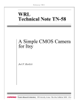
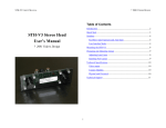
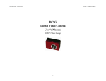
? 2001 VIDERE DESIGN
STH-MD1 USER’S MANUAL
STH-MD1/-C Stereo Head
User’s Manual
? 2001 Videre Design
1
? 2001 VIDERE DESIGN
STH-MD1 USER’S MANUAL
7.2
Table of Contents
1
Introduction....................................................................................... 3
2
Quick Start........................................................................................ 4
3
Hardware Overview........................................................................... 6
3.1
Hardware Schematic .................................................................. 6
3.2
Frame Rates............................................................................... 6
4
5
1394 Interface ................................................................................. 10
5.1
1394 Cable .............................................................................. 10
5.2
1394 Host Interface.................................................................. 10
6
User Controls .................................................................................. 11
6.1
Color ....................................................................................... 11
6.2
Gamma Correction .................................................................. 11
6.3
Video Digitization Parameters ................................................. 12
6.4
Subsampling............................................................................ 12
6.5
Subwindowing ......................................................................... 13
6.6
Electronic Pan and Tilt ............................................................ 13
6.7
Electronic Vergence................................................................. 13
6.8
Frame Rates............................................................................. 14
7
Installing the 1394 Host Card and Capture Software........................ 15
7.1
1394 Hardware and Drivers ..................................................... 15
7.1.1
MS Windows Hardware Installation ................................. 15
7.1.2
Linux Hardware and Driver Installation ........................... 15
8
Interface Software API.....................................................................17
9
Mounting Diagrams.........................................................................18
9.1
Bottom Mounting Diagram for the STH-MD1/-C. ....................18
9.2
Bottom Mounting Diagram for the STH-MD1/-C-Wide (Rev B)18
10
10.1
10.2
10.3
10.4
10.5
Lenses ............................................................................................... 8
4.1
Changing Lenses ....................................................................... 8
4.2
Cleaning the Imagers................................................................. 8
4.3
Imager Size ............................................................................... 8
4.4
F Number .................................................................................. 8
4.5
Focal Length.............................................................................. 8
4.6
Range Resolution....................................................................... 9
4.7
Field of View ............................................................................. 9
11
2
STH-MD1 Software .................................................................15
Technical Specifications...............................................................19
Geometry .................................................................................19
Interface...................................................................................19
Imagers ....................................................................................19
Full-frame rates........................................................................19
Physical....................................................................................20
Technical Support........................................................................21
? 2001 VIDERE DESIGN
STH-MD1 USER’S MANUAL
1
Introduction
The STH-MD1 is a compact, low-power digital stereo head with an IEEE
1394 digital interface. It consists of two 1.3 megapixel, progressive scan
CMOS imagers mounted in a rigid body, and a 1394 peripheral interface
module, joined in an integral unit.
The CMOS imagers are from PixelCam (now a part of Zoran Corporation).
They have 1288 H by 1032 V pixels, and come in either monochrome
(STH-MD1) or colorized (STH-MD1-C) versions. These imagers have
excellent dynamic range, sensitivity, anti-blooming, and noise
characteristics. They are fully controllable via the 1394 interface: the user
can set exposure, gain, subwindow, decimation, etc. They can be used
interchangeably with the same interface module.
The STH-MD1/-C uses standard C-mount lenses for user-changeable
optics. Wide-angle to telephoto options are available, depending on the
application.
The wide baseline version of the STH-MD1/-C has exactly the same
characteristics as the STH-MD1/-C, with the exception of range resolution
and mounting diagrams.
There are software drivers for the STH-MD1/-C for MS Windows
98/2000/XP, and for Linux 2.4.x kernels.
SRI’s Small Vision System (SVS) software has an interface to the STHMD1/-C. You can simply and automatically calibrate the stereo head,
perform stereo correlation, and view the results as a 3D set. The SVS
software includes all of the capture software described in this document.
3
? 2001 VIDERE DESIGN
STH-MD1 USER’S MANUAL
2
Quick Start
The STH-MD1/-C comes assembled, the interface module mounted to the
imager module. The module comes without mounted lenses.
To set up and test the STH-MD1/-C, you will need the following:
1.
Pair of C-mount lenses, for 2/3” or larger imager.
2.
Host computer with a 1394 PCI or PCMCIA card, OHCI
compliant.
3.
1394 6-pin cable.
4.
Capture software or Small Vision System installed on the host
computer.
Install the 1394 host card, if necessary, according to the directions in
Section 7.1. Install the video capture software (included with the STHMD1/-C) or Small Vision System software (see Section 7.2). This is the
not-so-quick part of the Quick Start.
Figure 2-1 Video capture program window.
Screw the lenses into the mounting holes on the stereo head. Be careful
not to force them initially, as you can cross-thread the lens mount. Snug
them down, but do not tighten excessively.
Pull down the Input chooser, and select the Video option. If everything
has been set up, the driver software will recognize and configure the stereo
head after a few seconds, and a success message will appear in the info text
window. If not, the Input chooser will go back to None, and an error
message will appear in the info window. Please see Section 7 for
troubleshooting.
Plug one end of the 1394 6-pin video cable into either 1394 jack on the
STH-MD1/-C, and the other into a 1394 port on the host PC. Note: for
PCMCIA cards, and laptops with a 4-pin Sony iLink port, an external
power supply and adapter are necessary to convert to a 6-pin (signal +
power) 1394 plug. Most PCMCIA cards come with this adapter.
To view stereo video, press the Continuous button. Left and right images
should appear in the application windows. If the message “Image timed
out” appears, then there is a problem with the IEEE 1394 drivers; please
see Section 7. If the images are too light or too dark, you can open the
manual iris of the cameras, or change the exposure and gain settings
(Section 6.3). Images can be saved using the File menu.
Start
the
video
capture
program,
smallv(.exe)
or
smallvcap(.exe), on the host computer. You should see a screen as
in Figure 2-1. The message window should indicate that the STH-MD1
interface is present. If not, go back to software installation (Section 7.2),
and follow the instructions for configuring the correct capture library.
A more complete description of the video capture program is in Section 6.
The SVS programs are described in the documentation that comes with
4
? 2001 VIDERE DESIGN
STH-MD1 USER’S MANUAL
that software. It is helpful to review Section 6 in conjunction with the SVS
documentation.
5
? 2001 VIDERE DESIGN
STH-MD1 USER’S MANUAL
video modes (frame size, decimation) will cause the frame rate to change,
and this will be reflected in the LED flash rate.
3
Hardware Overview
There are no user-settable switches on the STH-MD1/-C.
Figure 3-1 shows the hardware configuration of the STH-MD1/-C.
3.1 Hardware Schematic
The imager module has a milled Delrin frame that rigidly holds two
megapixel imagers, separated by a fixed distance of 9 cm. Lens mounts
are an integral part of the frame, and standard C-mount lenses are screwed
into these holders. There is an IR cutoff filter, with a knee at
approximately 700 nm, permanently mounted inside the lens holder. See
Section 4 for appropriate lens characteristics.
Figure 3-2 shows the design of the internal hardware of the STH-MD1/-C.
In the stereo imager module, two CMOS imagers, each of size 1288 x 1032
pixels, digitize incoming light into a digital stream. The imagers operate
in progressive mode only, that is, each line is output in succession from the
full frame.
The maximum video rate is 12 megapixels per second from each imager.
The imagers are synchronized to a common clock, so that the
corresponding pixels from each imager are output at precisely the same
time. Special interlace electronics convert the individual streams into a
single pixel-interlaced stream at 24 MHz. The interlaced stream contains
one byte from the left imager, then the corresponding byte from the right
imager, then the next byte from the right imager, and so on.
The interface module is mounted on the back of the stereo head. Two 1394
ports are placed at the top of the module. Either port can be used as a
connection to the host PC. The two ports allow daisy-chaining of the 1394
cable to other devices. Use only one port to connect the STH-MD1/-C to
the host computer!
A status LED indicates video imager activity. It will flash at half the frame
rate. It should begin flashing as soon as power is supplied to the camera
through the IEEE 1394 cable, since the imagers are always active, even
when images are not being acquired by the host computer. Changing the
The interlaced video stream is transferred to the 1394 interface module,
which communicates to the host PC over a 1394 digital cable. The module
also accepts commands from the host PC over the cable, and uses these
commands to control imaging modes such as exposure or subwindowing.
1394 ports
Right
C-mount
lens
The 1394 interface module can communicate at the maximum 1394 data
rate, 400 MBps.
LED
indicator
3.2 Frame Rates
Left
C-mount
lens
The 1394 interface electronics supports a maximum rate of 24 megapixels
per second. At this rate, there is no need for large buffer memories to hold
video data on the stereo device. At maximum frame size, the frame rate is
7.5 frames per second. Subsampling modes support higher frame rates,
from 26 fps at 640 x 480 to 110 fps at 320 x 240 (Section 6.8).
Figure 3-1. Physical layout of the STH-MD1/-C stereo head.
6
? 2001 VIDERE DESIGN
STH-MD1 USER’S MANUAL
Left
Imager
Imager
module
8-bit pixels
12 MHz per
imager
Right
Imager
Interlace
Electronics
1394
imaging
commands
Interlaced
pixels
24 MHz
1394
Interface
Electronics
1394
module
Digital
Video
Stream
1394
commands
1394
Digital
Cable
Figure 3-2 Schematic of the STH-MD1/-C electronics.
7
? 2001 VIDERE DESIGN
STH-MD1 USER’S MANUAL
small amount of methyl alcohol or similar lens-cleaning solvent, and wipe
the imager glass surface gently. Dry with a similar tissue.
4
Lenses
4.3 Imager Size
The STH-MD1/-C uses standard C-mount lenses. Good-quality, fixedfocus lenses with low distortion and high light-gathering capability are
best.
Lenses are characterized optically by imager size, F number, and focal
length. Following subsections discuss the choice of these values.
The imager size is the largest size of imager that can be covered by the
lens. For the STH-MD1, the lens must be 2/3” or 1”. 2/3” is an acceptable
size, but there will be a little vignetting (darkening) at the edge of the
image. A 1” lens will give much better illumination, but is typically
available only in longer focal lengths (12 mm or greater).
4.1
4.4 F Number
Changing Lenses
Standard C-mount lenses have a 1” diameter, 28 threads-per-inch screw on
their back end. The screw mates with the lens holder opening. To insert a
lens, place it back end on the lens holder opening as straight as possible,
and gently turn it clockwise (looking down at the lens) until it engages the
threads of the lens holder. If you encounter a lot of resistance, you may be
cross-threading the lens. Forcing it on will damage the plastic lens holder
threads.
The F number is a measure of the light-gathering ability of a lens. The
lower the F number, the better it is at pulling in light, and the better the
STH-MD1 will see in low-illumination settings. For indoor work, an F
number of 1.8 is acceptable, and 1.4 is even better. For outdoors, higher F
numbers are fine. In any case, it is useful to have a manual iris for high
light situations. While the imagers can have electronic exposure and gain
control to automatically compensate for different light conditions, the
acceptable illumination range can be extended by mechanical adjustment
of the lens opening.
Once the threads are engaged, continue screwing it on until it seats firmly.
You can snug it down, but do not tighten it excessively, since this can
damage the lens and the lens holder threads.
4.5 Focal Length
Removing the lens is the reverse process: unscrew the lens counterclockwise. There will be some initial resistance, and then it should
unscrew smoothly.
The focal length is the distance from the lens virtual viewpoint to the
imager. It defines how large an angle the imager views through the lens.
The focal length is a primary determinant of the performance of a stereo
system. It affects two important aspects of the stereo system: how wide a
field of view the system can see, and how good the range resolution of the
stereo is. Unfortunately there’s a tradeoff here. A wide-angle lens (short
focal length) gives a great field of view, but causes a drop in range
resolution. A telephoto lens (long focal length) can only see a small field
of view, but gives better range resolution. So the choice of lens focal
length usually involves a compromise. In typical situations, one usually
Normal care should be used in taking care of the lenses, as with lenses for
any good-quality camera.
4.2
Cleaning the Imagers
It should not be necessary to clean the imagers, since they are sealed off by
an IR filter inside the lens mount.
If dirt and dust are present on the IR filter surface, they can be cleaned in
the same manner as a lens. Wet a non-abrasive optic cleaning tissue with a
8
? 2001 VIDERE DESIGN
STH-MD1 USER’S MANUAL
STH-MD1/-C, b is 90 mm, and ? d is 0.46875 um (pixel size of 7.5 um,
divided by the interpolation factor of 16).
Figure 4-1 plots this relationship for several focal lengths. At any distance,
the range resolution is inversely proportional to the focal length.
4.7 Field of View
The field of view is completely determined by the focal length.
formulas for the FOV in horizontal and vertical directions are:
The
HFOV ? 2 arctan(4.8 / f )
VFOV ? 2 arctan(3.8 / f )
where f is in millimeters. For example, a 4.8 mm lens yields a horizontal
FOV of 90 degrees. This is about the smallest practical focal length for the
STH-MD1.
Figure 4-1 Range resolution in mm as a function of distance, for
several different lens focal lengths.
The following table shows the FOV for some standard focal lengths.
chooses the focal length based on the narrowest field of view acceptable for
an application, and then takes whatever range resolution comes with it.
4.6
Range Resolution
Range resolution is the minimum distance the stereo system can
distinguish. Since stereo is a triangulation operation, the range resolution
gets worse with increasing distance from the stereo head. The relationship
is:
r2
?r?
? d,
bf
Lens focal length
Horizontal FOV
Vertical FOV
4.8 mm
90 deg
73 deg
8.5
57
44
12.5
50
38
16
22
17
Table 4-1 Horizontal and vertical field of view for
different lens focal lengths.
where b is the baseline between the imagers, f is the focal length of the
lens, and ? d is the smallest disparity the stereo system can detect. For the
9
? 2001 VIDERE DESIGN
STH-MD1 USER’S MANUAL
capability of supplying power, and come with an adapter for supplying
power to the 1394 cable through a wall transformer.
5
1394 Interface
Any 1394 card is suitable, as long as it conforms to OHCI (open host
controller interface) specifications. All current cards do, but some older
cards may not.
Digital image information is transferred from the STH-MD1/-C to the host
PC via a 1394 cable. The cable sends a video stream from the imagers to
the PC, and sends commands from the PC to the stereo head to control
exposure, subsampling, etc. The cable also supplies power to the stereo
head.
5.1
1394 Cable
The STH-MD1/-C must be connected to the host PC via a 6-pin male-male
IEEE 1394 cable. The maximum length for such a cable is 4.5 m (about
15 feet). The cable supplies both signals and power to the stereo head.
Use only one cable! The two ports on the MEGA-D are for daisy-chaining
additional devices onto the IEEE 1394 bus.
The distance between the stereo head and the PC can be extended by using
a 1394 repeater.
Several 1394-enabled devices can be connected together, as long as the
connection topology doesn’t have any loops. The STH-MD1/-C can be
connected at any point in such a topology. At a maximum, it will need
about 60% of the bandwidth of a 400 MBps connection.
5.2
1394 Host Interface
The host computer must have an available 1394 port. Some portables and
desktops come with built-in ports. If these are 6-pin ports, they can be
connected directly to the STH-MD1/-C. Sony laptops also support an
alternative 4-pin 1394 cabling, which has the signal pins but no power.
There are adapters that convert from 4-pin to 6-pin styles; these adapters
use an external power supply transformer.
If the host PC doesn’t have a built-in 1394 port, one can be added by
installing a 1394 PCI card or PCMCIA card for laptops. 1394 PCI cards
have 6-pin ports, and supply power. PCMCIA cards do not have the
10
? 2001 VIDERE DESIGN
STH-MD1 USER’S MANUAL
6
two monochrome and one RGB color channel. The color channel
corresponds to the left image, which is the reference image for stereo. The
color image can be de-warped, just like the monochrome image, to take
into account lens distortion (see the Small Vision System User’s Manual).
User Controls
The CMOS imagers are fully controllable via the 1394 interface. User
programs may input color images (STH-MD1-C only), set video
digitization parameters (exposure, gain, red and blue balance),
subsampling modes, and region-of-interest (subwindowing). All of these
parameters can be set with the included capture application, or with the
SRI Small Vision System. They are also accessible to user programs
through the capture API (Section 8).
Color information from the camera is input only if the Color button is
pressed on the main window (Figure 2-1).
Because the typical color camera uses a colorizing filter on top of its pixels,
the color information is sampled at a lower resolution than a similar noncolorized camera samples monochrome information. In general, a color
camera has about ¼ the spatial resolution of a similar monochrome
camera. To compensate for the reduced resolution, use binning (Section
6.4) to increase the fidelity of the image. For example, if you need a
320x240 frame size, use 640x480 and binning x2.
User controls for frame size and sampling modes are on the main capture
window dialog. Video digitization and Subwindowing controls are
accessed through a dialog invoked with the Video… menu item. Figure 6-1
shows the dialog.
6.1
The relative amounts of the three colors, red/green/blue, affects the
appearance of the color image. Many color CCD imagers have attached
processors that automatically balance the offsets among these colors, to
produce an image that is overall neutral (called white balance). The
MEGA-D provides manual color balance by allowing variable gain on the
red and blue pixels, relative to the green pixels. Manual balance is useful
in many machine vision applications, because automatic white balance
continuously changes the relative amount of color in the image.
Color
Color information from the MEGA-D digital head (STH-MD1-C only) is
input as raw colorized pixels, and converted by the interface library into
The manual gain on red and blue pixels is adjusted using the Red and Blue
controls on the Video Parameters dialog. For a particular lighting source,
try adjusting the gains until a white area in the scene looks white, without
any color bias.
6.2 Gamma Correction
To display properly for human viewing, most video images are formatted
to have a nonlinear relationship between the intensity of light at a pixel
and the value of the video signal. The nonlinear function compensates for
loss of definition in low light areas. Typically the function is x? , where ? is
0.45, and the signal is called “gamma corrected.” Digital cameras, such as
the STH-MD1/C, do not necessarily have gamma correction. This is not a
Figure 6-1 Video Parameters dialog.
11
? 2001 VIDERE DESIGN
STH-MD1 USER’S MANUAL
problem for stereo processing, but does cause the display to look very dark
in low-light areas. You can add gamma correction to the displayed image
by choosing an appropriate gamma value in the slider under the right
display window (Figure 6-2).
6.3
6.4 Subsampling
In many applications it is not necessary to work with the the full 1288 x
1032 pixel array. The CMOS imagers are capable of sampling the pixels
in the array. Sampling allows the video stream to send less data, for faster
frame rates or less bus activity. A sampled image shows the same scene as
the original image, but it uses fewer pixels to do so, and has less detail.
Sampling differs from subwindowing, which picks a rectangular portion of
the image, but doesn’t change its resolution.
Video Digitization Parameters
The CMOS imagers have electronic exposure and gain controls to
compensate for varying lighting conditions. The exposure can vary from a
maximum of a full frame time to a minimum of one line time. Gain is an
additional amplification of the video signal, for low-light situations. It is
settable from 0 to 18 dB.
The PC capture interface supports two types of subsampling. Decimation
is a sampling technique in which only a portion of the pixel values are sent
back to the host PC. Decimation takes place at the CMOS imagers, so
frame rates can be much higher. The STH-MD1/-C supports decimation
by 2 and by 4.
Both imagers are treated in exactly the same manner. It is not possible to
set a different exposure or gain on each imager.
Binning is a subsampling technique in which several adjacent pixels are
averaged into one. Binning is superior to subsampling in that it reduces
video noise, sometimes quite substantially. However, binning does not cut
down on the video stream data rate for the STH-MD1/-C, since the binning
is done on the host PC.
Digitization control can operate in either manual or automatic mode.
Refer to Figure 6-1 for the controls in the video capture program. Manual
mode is the only currently supported mode for the STH-MD1/C.
In manual mode, the user program sets the exposure and gain. The
exposure and gain are based on a 0 to 100 scale. Here are some tips for
setting exposure and gain.
??
In general, keep the gain as low as possible, since it introduces
additional noise into the system. Use it only if the exposure is set
to maximum, or if the exposure must be kept low to minimize
motion blur.
??
Adjust the manual iris of the lens to as small an opening as
possible for your application, without having to use gain. This
will increase the depth of field and give better optical
performance.
Subsampling is always done in both the vertical and horizontal direction.
Subsampling x2 means that an image of size H x V will be transformed
into an image of size H/2 x V/2. Subsampling x4 transforms it to an image
of size H/4 x V/4.
12
? 2001 VIDERE DESIGN
STH-MD1 USER’S MANUAL
Figure 6-2 shows the frame size and subsampling controls on the video
capture application. Any x2 or x4 subsampling is allowed, including
combined binning and decimation.
6.5
Subwindowing
Often the area of interest in an image will be a small portion of the whole
image. In this case, there is no need to send all of the image data. The
CMOS imagers support subwindowing, where only the pixels from a
rectangular subwindow of the image are sent back. The imagers support
independent subwindowing in vertical and horizontal directions. The only
constraint is that the number of pixels in a line, or the number of lines in a
subwindow, must be a multiple of 8.
Subwindows are chosen using the Size pulldown menu in the capture
application. For example, 320x240 always outputs a 320x240 subwindow.
How much of the original image is shown depends on the decimation
mode. A decimation of x4, for example, means that the 320x240 subimage
covers almost the entire original image. With a fixed subwindow size, you
can think of subsampling as electronic zoom.
6.6
Sampling mode
Electronic Pan and Tilt
Since a subwindow doesn’t occupy the whole image, it can be placed at
different positions within the image. The subwindow position can be set by
user commands, effectively creating an electronic pan/tilt feature as the
subwindow is moved.
Frame size
Gamma
correction
Figure 6-2 Frame size and Subsampling controls in the main capture
window.
6.7 Electronic Vergence
The placement of the subwindow is controlled by specifying the location of
its upper left corner, as an X and Y offset in pixels. Figure 6-1 shows the
location of the subwindow offset slider controls in the Video Parameters
dialog.
Your eyes verge when looking at close objects, that is, they point inwards
from a parallel view. Vergence is important when viewing close objects,
because it allows the object to be centered in each image.
The STH-MD1/-C supports electronic vergence, which simulates
mechanical vergence. In electronic vergence, the horizontal offset of the
left subwindow differs from that of the right. This differential offset
effectively causes the imagers to point inwards towards the close object.
13
? 2001 VIDERE DESIGN
STH-MD1 USER’S MANUAL
The vergence control is on the Video Parameters dialog (Figure 6-1).
6.8
Frame Rates
Frame rates from the STH-MD1/-C depend on two factors: decimation and
the number of image lines in a subwindow. It does not depend on the
length of a line, since the CMOS imagers always use the same time to
output a line, no matter how many pixels it contains.
Table 6-1 shows the frame rates for maximum frame sizes in each of the
decimation modes. To calculate an actual frame rate, divide the frame rate
by the fraction of lines in the actual subwindow. For example, at
decimation x2, a subwindow of size N x 240 would have a frame rate of 53
fps (26 / (240/512)).
Decimation
Frames per Second
x1 (1288 x 1032)
7.5
x2 (644 x 512)
25
x4 (322 x 256)
80
Table 6-1 Frame rates at different decimations.
14
? 2001 VIDERE DESIGN
STH-MD1 USER’S MANUAL
7.1.2 Linux Hardware and Driver Installation
Installing the 1394 Host Card and Capture
Software
Linux kernels 2.4.x are required for operation. Please see the Videre
Design website (www.videredesign.com/support_svslnx.htm) for current
information.
The STH-MD1/-C connects to a host computer via a digital 1394 interface.
The host PC must have a 1394 port, and software to interface to the video
stream from the camera. This interface software presents the video stream
from the 1394 hardware as a set of stereo frames to the user program (see
Figure 7-1). The STH-MD1/-C comes with interface software for either
MS Windows 98/2000/XP or Linux.
Sometimes the 1394 system will get hung and you have to unhang it by
removing all the modules, and re-installing them. Also, the Linux IEEE
1394 drivers sometimes do not configure the root node of the bus properly.
Check the listing of /proc/ohci1394 to see if the word “root” appears near
the top of the listing. If not, you can sometimes get around this problem by
using:
7
7.1
modprobe ohci1394 attempt_root=1
1394 Hardware and Drivers
when installing the OHCI 1394 module.
Before installing the software interface, the PC must be equipped with a
1394 port. If there is one already present, on the motherboard, then you
can skip this section. Otherwise you have to install a PCI or PCMCIA
card. The card must be OHCI compliant, which all current cards are.
7.2 STH-MD1 Software
The STH-MD1/-C comes with interface software and several sample
applications, including the capture application described in this manual.
7.1.1 MS Windows Hardware Installation
MS Windows 98SE, ME, 2000, or XP is required.
To install the software under MS Windows, execute the file
svscap21X.exe. The installation process will add the relevant
interface and application software.
For a PCI card, insert the card into a free PCI slot with the computer power
off, and start the computer. With a PCMCIA card, insert it into the
PCMCIA slot. In either case, the New Hardware wizard will walk you
through installation steps for the low-level drivers. You may need your
MS Windows 98/2000 CD to install some files.
To install the software under Linux, untar the file svscap21X.tgz in a
new directory, which will become the top-level directory of the software.
You should also set the environment variable SVSDIR to this directory,
and add bin/ to your LD_LIBRARY_PATH variable.
1394
video
stream
1394
PC
Hardware
Low-level
1394
driver
STH-MD1
interface
software
The directory structure for the software is:
To
user
program
bin/
smallvcap(.exe)
smallv(.exe)
smallvcal(.exe)
stcap(.exe)
stdisp(.exe)
svsgrab.dll/lib
Figure 7-1 Host PC low-level software structure.
15
? 2001 VIDERE DESIGN
STH-MD1 USER’S MANUAL
libsvscap.so
pixcap.so
svspix.dll/lib
stereo calculation libraries
src/
flwin.cpp
svs.h
flwin.h
samples/
stcap.cpp
stdisp.cpp
*.dsw, *.dsp, makefile
serve as a template for user programs that integrate stereo capture from the
STH-MD1/-C.
libsvscap.so and svsgrab.lib/dll are the capture libraries for
Linux and MS Windows, respectively. These libraries must be set to the
correct ones for the MEGA-D. Copy the following files in the bin/
directory:
pixcap.so -> libsvscap.so
svspix.dll -> svsgrab.dll
svspix.lib -> svsgrab.lib
(Linux)
(MS Windows)
(MS Windows)
There is a convenience program for MS Windows, setup_megad.bat,
which will perform the copies when double-clicked.
There are several applications. The source code for all applications is
included in the distribution. The stereo calculation libraries are also
included, so that user applications can link to them. The calibration
libraries are not included; the only way to run the SVS calibration
procedures is through the smallvcal(.exe) application.
You can check that the correct interface library is installed, by looking at
the information text when the capture application is started. It should say
“MEGA-D digital stereo interface”. If not, the wrong interface library is
installed in svsgrab.dll or libsvscap.so.
smallvcap(.exe) is a GUI-based application that allows the user to
exercise the capture functions of the STH-MD1/-C. It is described in
earlier sections of this document.
smallv(.exe) is similar to smallvcap, with the addition of SRI’s
stereo calculation libraries for realtime depth analysis. You must have
installed the full SVS system to run this application.
smallvcal(.exe) is the same as smallv, with the addition of a
calibration package for calibrating a stereo rig. Use this application to
perform calibration on your stereo system.
stcap(.exe) is a simple application that connects to the stereo head
and displays images. It can serve as a template for user programs that
integrate stereo capture from the STH-MD1/-C.
stdisp(.exe) is a simple application that connects to the stereo head,
grabs images and performs stereo analysis, and displays the results. You
must have installed the full SVS system to run this application. It can
16
? 2001 VIDERE DESIGN
STH-MD1 USER’S MANUAL
8
Interface Software API
Please see the Small Vision System manual for information about the
software API for capturing and saving images.
17
? 2001 VIDERE DESIGN
STH-MD1 USER’S MANUAL
9
9.1
9.2 Bottom Mounting Diagram for the STH-MD1/-CWide (Rev B)
Mounting Diagrams
The three holes are threaded for ¼-20 machine screws (standard tripod
mounting screw).
Bottom Mounting Diagram for the STH-MD1/-C.
The larger hole is threaded for a ¼-20 machine screw (standard tripod
mounting screw). The two smaller holes are threaded for 6-32 machine
screws.
18
? 2001 VIDERE DESIGN
STH-MD1 USER’S MANUAL
10 Technical Specifications
Format
Monochrome, 8 bits / pixel
Color, 8 bits / pixel, Bayer pattern
10.1 Geometry
Scan mode
Progressive
Rigid milled Delrin frame
Pixel size
7.5 um square
9 cm, fixed
Sensitivity
1 lux
Housing
Baseline
Imager size
2/3 inch diagonal
Exposure
Electronic, 0.1 ms to frame time
Lens type
C mount, interchangeable
Gain
10.2
6 to 20 dB
Resolution
1288 H x 1032 V
Interface
Decimation
x1, x2, and x4
Type
Digital 1394 [Firewire], OHCI compliant
Subwindow
Arbitrary rectangular subwindow
Speed
Maximum 20 megapixels / second
Host interface
Any 1394 OHCI card
10.4
Host OS
No decimation
1280 x 1032: 7 Hz
Windows 98 / 2000, Linux
10.3
Full-frame rates
Decimate by 2
640 x 512: 25 Hz
Imagers
Decimate by 4
320 x 256: 80 Hz
Type
Zoran PCS2112 CMOS
19
? 2001 VIDERE DESIGN
STH-MD1 USER’S MANUAL
[Subwindowed frames are proportionally faster, e.g., N x 640 images at
no decimation are 15 Hz]
10.5
Physical
Power
2 watts
Cabling
Single 6-pin 1394 cable (power and signal)
Stereo module size
5" x 1.75" x 1"
1394 module size
3.5" x 2.5" x 0.75"
Weight (without lenses)
6 ounces
20
? 2001 VIDERE DESIGN
STH-MD1 USER’S MANUAL
11 Technical Support
For technical support, please contact Videre Design by email or FAX.
Videre Design
P.O. Box 585
Menlo Park, CA 94026-0585
Fax: (650)323-3646
Email: [email protected]
Technical information about stereo algorithms and stereo calibration can
be found at www.ai.sri.com/~konolige/svs .
21