1
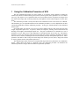
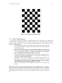
1 Small Vision System Calibration SRI Small Vision System Calibration Supplement to the User’s Manual Software version 2.2b July 2001 Kurt Konolige and David Beymer SRI International [email protected] http://www.ai.sri.com/~konolige Small Vision System Calibration 2 1 Using the Calibration Procedure of SVS _______________________________ 3 1.1 Getting Started ______________________________________________________ 4 1.2 Setting the Camera Characteristics _____________________________________ 6 1.3 Input Images ________________________________________________________ 7 1.3.1 1.3.2 1.3.3 1.3.4 Image size _____________________________________________________________ 7 Planar Target ___________________________________________________________ 7 Planar Target Placement __________________________________________________ 8 Saving Calibration Images_________________________________________________ 9 1.4 Finding Features____________________________________________________ 10 1.5 Image Scaling ______________________________________________________ 11 1.6 Calibration Calculation ______________________________________________ 12 1.6.1 Calibration Parameters___________________________________________________ 14 1.7 Troubleshooting ____________________________________________________ 16 1.7.1 1.7.2 1.7.3 No Convergence _______________________________________________________ 16 Bad Calibration Parameters _______________________________________________ 16 Poor Rectification ______________________________________________________ 16 2 Technical Aspects of Calibration ____________________________________ 17 2.1 Camera Model _____________________________________________________ 18 2.2 Rectification _______________________________________________________ 20 2.3 3D Reconstruction __________________________________________________ 21 2.4 Setting the horopter _________________________________________________ 22 Small Vision System Calibration 3 1 Using the Calibration Procedure of SVS The SVS Calibration Procedure for stereo cameras is an efficient, simple method for finding the internal (lens distortion and decentering) and external (camera spatial offset) parameters of a two-camera stereo rig. The output is a set of parameters that can be used with the SVS to warp the stereo images from the cameras into images that would be produced by ideal pinhole cameras whose imagers are in the same plane. The calibration procedure is briefly described in the Calibration section of the SVS User’s Manual. This document gives an expanded treatment of the calibration procedure, as well as helpful hints to those experiencing difficulties with the calibration procedure. It also gives technical details of the calibration and its results. In an ideal setting, the cameras of a stereo rig are perfect pinhole cameras, with exactly the same focal length, and parallel optical axes. In practice, cameras are imperfect, suffering from lens distortion and differing focal lengths, and misaligned optical axes. The goal of calibration is to determine two sets of parameters, intrinsic and extrinsic, that compensate for the imperfections in the stereo rig. The intrinsic parameters correct lens distortion and uneven focal length; the extrinsic parameters determine the spatial offset of the two cameras, including the stereo baseline and any deviation from parallel optical axes. These parameters can then be used to warp the camera images into standard position, that is, images that would be seen by pinhole cameras with parallel optical axes. The calibration procedure in SVS uses a simple planar target that can be printed out on a standard PC printer. When shown the target in 5 different views, the calibration procedure can determine the calibration parameters using an efficient nonlinear optimization procedure. 4 Small Vision System Calibration 1.1 Getting Started The calibration procedure is part of the smallvcal application. The necessary calibration routines are compiled into the application. To run the calibration procedure, select the menu item Calibration at the top of the smallvcal window. This will bring up a calibration dialog window, as shown in Figure 1-1 below. Calibration requires 5 different image pairs of the checkerboard calibration object, which can either be input live, or from stored files. To familiarize yourself with the procedure, it is helpful to run through the procedure using stored images available in the data/calN-X.bmp files. Click on the Load All button at the top right of the dialog to bring up a load dialog, and choose the data/cal1-L.bmp image. The stereo images will be loaded into the windows, starting with cal1-L/R.bmp. Choose the Features button on the bottom of the dialog to find the corners of the checkerboard squares for all images (the one to the right of the image display finds features for just the displayed image pair). After 20 seconds or so, the images will show green crosses where the feature-finder detected the corners. Once all the features have been detected, choose Debug from the smallvcal menu bar to bring up a debug output box, so you can see the intermediate steps in the calibration process. Then choose Calibrate at the bottom of the internal calibration dialog. At this point, the calibration routines will attempt to find a Input image display Info line Feature display buttons Camera characteristics (input) Calibration target type (input) Stereo parameters (output) Action buttons Figure 1-1 Initial Calibration Dialog window. Small Vision System Calibration 5 good set of parameters for the images you have input, using a nonlinear optimization technique. The debug output box will show the progress of the routines. The first message will tell you which pair of images were selected as a starting point for an estimate. Then, successive image pairs are added to the mix, and the estimated parameters recalculated. If an acceptable set of parameters is found (the reprojected points are close to the image points), then the calculation proceeds. If all image pairs are added successfully, then the final estimated parameters are displayed in the calibration window (Left intrinsics, Right intrinsics, and Extrinsics). You can save the parameters to a file, which is recommended, and close the calibration dialog with the OK button to send the parameters to smallvcal. If no good set of parameters is found, the current parameter estimate is abandoned, and the process starts over with a new image pair. On particularly difficult image sets, the process can take 15 minutes or more to converge to a good parameter set. It helps to bring up the Debug window to watch the progress of the calculation, and assure yourself that something is happening; the progress is also indicated in the info line in the calibration dialog. Note that the calibration dialog and smallvcal windows are unresponsive during the calculation, except for a brief moment when the next image pair is added. In some cases, no good parameter set will be found at all, and the procedure will terminate after trying all the different starting pairs. In other cases, the parameters that are output will not be good ones, even though the optimization procedure indicates that they are. The purpose of this document is to help in these cases, and in giving tips for the efficient use of the calibration procedure. Small Vision System Calibration 1.2 6 Setting the Camera Characteristics The calibration procedure must have knowledge of the cameras that produced the input images. This is true whether you use stored or live images. Each image pair must come from the same stereo rig: you can’t mix image sets taken from different stereo rigs. Also, each camera in the stereo rig must have approximately the same characteristics, i.e., the same lens focal length and imager type. There are preset values for the stereo heads sold by Videre Design: the STH-V2 and STH-V3 analog heads, and the MEGA-D megapixel digital head. Choosing one of these stereo head types, in the camera characteristics section of the dialog, sets most of the required values. The only choice remaining is whether to use Kappa2 or not. This choice is discussed in a section below. If you want to calibrate a stereo rig other than the Videre Design stereo heads, then you must choose the Custom setting and input the camera parameters. Usually these parameters can be found from the specifications of the cameras. Note well: For custom stereo rigs, the calibration procedure is very sensitive to the camera characteristics. If the input characteristics do not match the actual camera values, it is usually not possible to get a good set of calibration parameters. In the Custom mode, the required parameters are the width and height of the camera imagers (in pixels), and the pixel size. For example, the imagers in the STH-V2 stereo head are 320x240 pixels, and each pixel is 0.0144 mm (width, or dx) x 0.0138 mm (height, or dy). These are the active pixels, that is, the ones that actually contribute to the output signal of the camera, which in this case is an NTSC video signal. The imager itself has 356 x 288 pixels, so that it can also output a PAL video signal. If you were using a PAL framegrabber, then you would use the larger imager size. Note well: The imager size is not the same as the image size captured into memory by a framegrabber. For analog cameras, the camera outputs a video signal (usually NTSC or PAL), which is then digitized by a framegrabber. The framegrabber can scale the image, for example, it will usually produce a 640-pixel line from an NTSC signal, even if the imager only has 320 pixels in each line. In any case, you must use the number of pixels on the imager that produce the output image, rather than the number of output pixels digitized by the framegrabber. Digital imagers, such as the MEGA-D, output each pixel’s value, and so the output image from the camera corresponds directly to the number of pixels in the imager. The aspect ratio is the ratio between the width and height of each pixel in the imager. Although the aspect ratio is fixed on the imager itself (because every pixel has the same size), an analog framegrabber can change the aspect ratio by digitizing the video stream at a different pixel rate than it was produced. To adjust for slight variations in the aspect ratio, the calibration routines can search for a modified aspect ratio to use in place of the original one. For analog stereo heads (the STH-V2/V3), the Fixed Aspect box should be unchecked, to allow for this search. Digital stereo heads (the MEGA-D) should fix the aspect ratio, because the output image corresponds directly to the pixels on the imager. The Kappa2 value is a parameter to correct for lens distortion. Allowing the calibration routines to search for a good value for Kappa2 can help with lenses that have a large amount of distortion, which is most noticeable on wide-angle lenses (> 50 degree field of view). The calibration dialog allows you to fix Kappa2 at 0, so that the search is not performed. In general, leave this box unchecked, unless you have trouble with the calibration parameters that are produced (Section 1.6.1) 7 Small Vision System Calibration 1.3 Input Images The quality of the calibration depends mostly on the input images that are given to the calibration procedure. In addition, some sets of input images will make it difficult or impossible for the calibration procedure to converge. Here we give some general tips for the characteristics of good input images. 1.3.1 Image size A large image size helps the feature finder to accurately locate the corners of the target checkerboard, and leads to a more accurate calibration. However, larger sizes also make feature-finding more difficult, because there is more image area to search. A good compromise is to use 320x240 images, if they are available from the framegrabber or digital stereo rig. Table 1-1 gives the recommended input image sizes for Videre Design stereo heads. Some cameras and framegrabbers let you input a subwindow of the full image produced by the camera. If you are going to work with just this subwindow, then you should use the subwindow for your input images. In most cases, however, you will work with the full image produced by the cameras, and the input images for calibration should encompass the full image size. For example, with the MEGA-D megapizel digital imager, the full image size is 1280 x 960 pixels. This is rather large for the feature finder, so for inputting images, it is best to put the MEGA-D into a mode where the output image is only 320 x 240, but encompasses the full space of the original 1280 x 960 image. The MEGA-D has a subsampling mode that effectively reduces the output image resolution, while maintaining the same spatial extent of the image. The preferred Subsampling mode is to decimate the image by a factor of 2, and to further average (bin) the image by a factor of 2. This gives a total reduction of x4, producing a full-field 320x240 image. Analog framegrabbers also allow image reduction of the output image by scaling the resolution of the image. For the STH-V2 and V3 stereo heads, in line interlace mode, it is best to ask for output images of size 160x120. These images are scaled by the framegrabber to encompass the full original field of the imager. 1.3.2 Planar Target The calibration procedure requires a set of 5 image pairs of a planar checkerboard target. The standard target is in data/check.pdf. Print out the target on a standard 8.5 x 11 inch sheet of paper (or A4 paper), making sure to specify 1:1 scaling in the printer options (do not specify “fit to page,” which will stretch or shrink the image). Paste the printed pattern to a flat object, such as a cutting board or a clipboard. Figure 1-2 shows an image of the checkerboard. Most stereo rigs can be calibrated with the standard target, which is convenient because it fits on a single sheet of paper. In some cases, the standard target is not sufficient: it is impossible to view the target in both images at a large enough size. This situation typically occurs with long focal length lenses and wide baselines, where the target must be placed far from the camera in order to appear in both images. For those stereo heads sold by Videre Design, only the wide baseline MEGA-D should require this target. In these situations, the file data/check4.pdf should be used. This file contains a set of 4 images, which comprise a target with a larger square size (54 mm vs. 27 mm for the standard target). Print out the four sheets, and paste them together on a flat board; some overlap is required. Be sure to check the check4.pdf button in the panel square size region. For some custom stereo rigs, even the larger target may not be sufficient. The calibration dialog allows you to use any size target you care to make; just input the square size as a custom target size. Stereo Head STH-V2, STH-V3 MEGA-D Recommended image size 160 x 120 320 x 240, bin x2, dec x2 Table 1-1 Recommended input image sizes for Videre Design stereo heads. 8 Small Vision System Calibration Figure 1-2 Checkerboard calibration object. 1.3.3 Planar Target Placement The placement of the planar target in a calibration image set is a critical factor in getting good calibration results. The planar target itself is in data/check.pdf. Here are some hints on how to capture a good set of images of the target. You can also check the calibration images in data/calN-X.bmp to see an example of a good image set. 1. Try to have the target fill up a large portion of the image in each camera. This will give corner features that are spaced far apart, which is best for the feature finder and the calibration routines. 2. Have at least one image pair where the target is almost parallel to the cameras, and fills up a good portion of the image. This will help the calibration routines find the correct image distortion parameters. Caution: if the target is too close and too large, it is difficult for the calibration routines to converge. 3. For most of the images, show the target slanted away from or towards the cameras, so that the squares appear at different depths. Vary the slant in the image pairs, so some slant vertically, others horizontally. 4. In addition to (3), have at least one image at a very different depth from some of the other images. Note that this can conflict with (1), since you may have to put the image farther away from the cameras. Caution: if the target is too far and too small, it is difficult for the calibration routines to converge. 5. For several of the images, have the target come close to one of the edges of the images. Most problems with convergence and calibration arise because of the input images. Typically, a good set of images will cover the image field, and adhere to the guidelines above. It is especially important not to place the target too far or too close. The images in Figure 1-3 show a good set of target placements for calibration; these can be used as guidelines for how to capture a calibration set. Small Vision System Calibration 9 Figure 1-3 Typical calibration image set (left images only). Note the good coverage of the image field, and the different slants. 1.3.4 Saving Calibration Images It’s a good idea to save image pairs that are captured from a live video source. In this way, you can reinput the images if the program crashes, or if for some reason there is a problem producing a good set of calibration parameters. The stored images can also be sent to SRI International for debugging. Please use the Save All button for this purpose, since it makes it easier to input them. Small Vision System Calibration 1.4 10 Finding Features The calibration procedure first must find the image features in each of the image pairs. These features are the corners where 2 black and 2 white squares just touch. You can invoke the feature-finder for each image pair as it is acquired at the top of the dialog, or find features in all images by using the button at the bottom of the dialog. When the feature-finder is finished, it will print an information message about the results. Normally, the feature-finder is very robust, and it will succeed; in this case, the found features are displayed as red crosses in the images. You can verify that the features are correct by looking at the placement of the crosses: if any of them are obviously incorrect, you should delete the image pair and get a new one. There are two conditions under which the feature-finder may fail: 1. The image lighting is poor. If the checkerboard image is washed-out or obscured in some way by lighting, the feature-finder won’t be able to work correctly. 2. The checkerboard is too small. The target must be a reasonable size in the image, so that the corners will be detectable. Again, if these conditions cause the feature-finder to fail, just delete the image pair and get a new one. Note well: the camera characteristics must be specified before running the feature finder. If they are changed after features are found, the calibration procedure will not work correctly. Small Vision System Calibration 1.5 11 Image Scaling Before performing calibration, one more option should be checked. The calibration parameters tell how to warp an input image to a rectified output image. The input and output images both have the same size, for example, a 320x240 input image is warped to a 320x240 output image. In the warping process, the output image can be scaled to contain just a portion of the input image. Generally, there are two extremes for the scaling: 1. Every output pixel is mapped to some input pixel (i.e., there are no blank areas in the output image, put some portion of the input image may not appear). 2. Every input pixel is mapped to some output pixel (i.e., the full scene appears in the output image, but some pixels in the output image may be blank). Figure 1-4 shows the difference between the two. On the left, the original input image contains a large amount of lens distortion. The middle image is rectified, and slightly enlarged so that it comes from the middle portion of the input image. Note that the doorway on the right is not fully present in the middle image. Every pixel in the output image comes from a pixel in the input image. In contrast, the rectified image on the right is slightly reduced from the original image, so that every original image pixel is mapped to the output image. Note the blank areas on the sides of the image. The dotted rectangle shows how the middle image fits – it is a smaller rectified image, expanded to fill the 320x240 rectangle. The choice of reduced or expanded rectified image must be made before the calibration process is invoked. The scale check box controls this choice. If it is checked, then a reduced-scale calibration is produced; if it is unchecked (the default), then the enlarged-scale calibration is produced. If the lens distortion is not extreme, the enlarged output image is generally preferred, since there are no blank areas to confuse the stereo processing. But if the lens distortion is high, the reduced output image may be better, since no information is lost. Figure 1-4 Effect of scaling during the rectification process. All images are 320x240. Left image is the orginal. Middle image is rectified, and enlarged slightly so that all output pixels are mapped. Right image is reduced so that all input pixels are mapped. Small Vision System Calibration 1.6 12 Calibration Calculation After finding features in all 5 images, the calibration procedure can be invoked by pressing the Calibrate button at the bottom of the dialog. But before doing so, it is useful to invoke the Debug menu item from the smallvcal application. This brings up a dialog window in which the progress of the calibration calculation can be observed. If there is a problem with the procedure, it can be diagnosed here. Figure 1-5 shows typical output in the Debug window, from a successful calibration. Initially, the procedure picks an image pair (1,2) to make an estimate of the calibration parameters. The estimate is a nonlinear optimization, which tries to find the best fit among all the possible internal and external parameters. Once the parameters are estimated, the results are used to back-project the 3D position of the features onto the images, to compare with the placement found by the feature-finder. If the parameters are good, then the back-projection will be close. This is the value printed out in the Debug window, the backprojection error. To be successful, each step of the process must produce an error less than 2.0 pixels. For stereo rigs with good lenses, the average error will be much less, usually several tenths of a pixel. After the initial estimate, image pairs are added, one at a time, and the nonlinear optimization procedure again attempts to find a good set of parameters, starting with the current parameter estimate. If the new estimate produces a small back-projection error, it is accepted, and the next pair is added. If the error is too large, then the current estimate is abandoned, and a new starting pair is chose to restart the process. Once all the image pairs have been successfully added, the final parameters are output in the display at the bottom of the calibration window, where they can be examined. Also, the back-projected points are displayed on the calibration images, so they can be checked for accuracy against the original feature points. Figure 1-6 shows the result of the calibration procedure applied to the calibration images in the data/ directory. Figure 1-5 Debugging output during the calibration process. Small Vision System Calibration Figure 1-6 Results of the calibration procedure on the SVS calibration dataset. The yellow crosses show the back-projected position of the corner features. 13 Small Vision System Calibration 1.6.1 14 Calibration Parameters The parameters returned by a successful calibration are guaranteed to be correct, in the sense that they will transform the 5 input images into images as seen by pinhole cameras that have parallel optical axes. In almost all cases, they will give physically plausible values for the intrinsic and extrinsic parameters. For example, the cameras used in the images of Figure 1-6 were rated at 7.5 mm, and they were placed approximately 9 cm apart, with parallel optical axes. So, we expect the returned focal lengths to be about Figure 1-7 Calibration parameters for a small focal length lens. Small Vision System Calibration 15 7.5 mm, and they are 7.786 mm (left) and 7.823 mm (right), which is close. The remaining intrinsic parameters are concerned with lens distortion. Lens decentering is a deviation of the lens optical axis from the center of the imager. The estimated lens center is returned as the parameters Cx,Cy. These parameters should be close to the image array center, which in this case is (640,480). Finally, the lens radial distortion is the deviation of the lens convergence from a true pinhole projection. This distortion is modeled by two parameters, Kappa1 and Kappa2, which determine how much the image stretches (positive) or shrinks (negative) away from the lens center. Most lenses have a small amount of positive radial distortion; lenses with very short focal lengths tend to have larger amounts. In this case, the lenses have a Kappa1 value of about +0.0027, and Kappa2 has been set to 0. Lenses with smaller focal lengths will have larger Kappa1 values than this, but generally won’t exceed about +0.01. Figure 1-7 shows the calibration parameters for a very small focal length lens (2.1 mm). You can see the extreme radial distortion in the images at the top of the calibration dialog. Still, Kappa1 is only +0.06. The extrinsic parameters show how the cameras are situated relative to each other. All these numbers should be small, except for the value of Tx. This is the baseline between the cameras, and it should be a negative number of approximately the right size (in this case, 90 mm is the baseline estimate from the stereo rig design). All of the other extrinsic parameters in Figure 1-6 are small; for example, the value of Tz is just –0.3 mm, which indicates that the right imager is estimated to be –0.3 mm behind the plane of the right imager. One good way to check the parameters is to apply them to the calibration images themselves. Transfer the parameters to the smallv main window by pressing the OK button (but first save the parameters!). Then, in smallv, load one of the calibration image pairs, and press the Warp and Continuous button to see the effects of the warping. Check that the straight lines of the calibration target all appear straight in the rectified images. Also, pick a particular square, and check that it appears at the same height in each of the images. Small Vision System Calibration 1.7 16 Troubleshooting There are two problems that can occur during the calibration calculation. 1. The calibration procedure does not converge. 2. The calibration procedure converges, but converges to values that are physically incorrect. 3. The calibration procedure converges and the values are physically correct, but the rectification results are not good, especially around the edges of the images. 1.7.1 No Convergence Another problem is that the procedure does not converge (after many tries, the calibration calculation will sometimes give a segmentation fault). The two most common reasons for non-convergence are: 1. Camera characteristics are not set properly. Make sure that you have chosen the correct camera type in the setup dialog. The camera type must be chose before the features are found in the images. 2. Input images are difficult for the procedure. Typically, the procedure will fail consistently when trying to add one particular image pair. You can verify this by choosing the Debug menu item from the smallv main window; the procedure will add image pairs successfully up to the problem image, and then fail. In many cases, this image will violate the guidelines of Section 1.3.3, that is, it will be too far or too close to the cameras. A quick way to recover from this problem is to replace the offending image pair with an image pair from the calibration set. There will be a redundant pair in the calibration set, but usually this will not cause problems for the calibration procedure. 1.7.2 Bad Calibration Parameters In rare cases, the calibration procedure will converge to parameter values which are not physically correct, although they are possible. The problem is that the input images do not give enough information to determine a unique solution, and the procedure converged on the wrong one. Generally, this will happen only if there are not enough images with depth variation (the planar target slanted towards or away from the camera). In this case, there are two possible remedies. The first is to set Kappa2 to 0 in the camera characteristics field of the calibration window. Allowing a second radial distortion parameter increases the chances for ambiguity, and restricting it can often lead to a good solution. The second remedy is to simply capture another set of calibration images, paying attention to the guidelines in Section 1.3.3. If you have chosen the wrong camera type, then the procedure may converge, but the calibration parameters will not be correct: for example, the focal length returned by the procedure will not correspond to the actual focal length of the lens. In fact, it is possible to use this calibration and retrieve good 3D information from the stereo head, since the calibration was done with respect to a real-world target. It will just report the wrong parameters for the cameras. 1.7.3 Poor Rectification After transferring the calibration parameters to smallv, you can check them by rectifying some images. Generally, the calibration images themselves will rectify correctly, because they were used in the rectification process. If the target in the calibration images did not cover the image field well, there may be problems with rectification in the areas not covered by the target. The only remedy here is to re-take some of the calibration images, getting more coverage of the image field. Small Vision System Calibration 17 2 Technical Aspects of Calibration The full calibration procedure uses a number of views of a calibration object to estimate a model for the stereo head cameras. It utilizes a fairly complete model with 16 parameters. We now describe the camera model and its use in calibration. 18 Small Vision System Calibration 2.1 Camera Model Our model of the SVS stereo head consists of internal parameters of both the left and right cameras and the external parameters describing the rigid transformation between the two cameras. First we describe the internal parameters. These parameters describe the distortions introduced in each individual camera by imperfect lenses and lens placement. The biggest effects are from radial distortion, in which the image is compressed towards the edges; and lens decentering, in which the center of focus of the lens is not at the center of the imaging array. The effects are most prominent in wide-angle lenses; lenses with viewing angles of 50 degrees and less generally will not need any correction to help the quality of stereo matching. However, if range accuracy is important, then even narrow field lenses should be corrected. The correction is done digitally, by warping the nonideal image into the image that would be produced by an ideal camera. (C x , C y ) Camera center, pixels f κ 1 ,κ 2 sx Focal length, mm Radial distortion parameters Aspect ratio Table 2-1 Intrinsic camera parameters. Our model of the camera intrinsics includes the parameters listed in Table 4-1 and follows the model T of Tsai 1. Given a 3D point P = ( X , Y , Z ) in left camera coordinates, we map to screen coordinates using the following steps. First, we project P to the image plane using the standard perspective equations Xu = f X Z Yu = f Y , Z (4.1) where ( X u , Yu ) is the undistorted image coordinates. Next, radial lens distortion is modeled by X u = X d (1 + κ 1 r 2 + κ 2 r 4 ) Yu = Yd (1 + κ 1 r 2 + κ 2 r 4 ) , (4.2) where ( X d ,Y d ) are the distorted image coordinates and r 2 = X d2 + Yd2 . Finally, the distorted image coordinates are mapped to screen coordinates ( X f , Y f ) using Xf = sx X d + Cx dx Yf = 1 Yd + C y , dy (4.3) where d x and d y are the horizontal and vertical spacing between sensor elements on the image array. Since the calibration calculations are currently performed assuming an image size of 320x240, d x is fixed at 0.0144 mm/pixel and d y at 0.0138 mm/pixel. Given these intrinsic parameters, one can apply an image warp to correct for lens distortion or map from 3D image coordinates to 2D screen coordinates. For example, we can correct for radial distortion by resampling the image I left as if κ 1 = 0 undist I left ( x, y ) = I left ( x' , y ' ) , where ( x' , y ' ) is related to ( x, y ) through equations (4.2) and (4.3), as shown in Table 4-2. 1 Tsai, Roger Y. “A Versatile Camera Calibration Technique for High-Accuracy 3D Machine Vision Metrology Using Off-the Shelf TV Cameras and Lenses”, IEEE Journal of Robotics and Automation, vol. RA-3, no. 4, August 1987, pp. 323-344. 19 Small Vision System Calibration ( X u , Yu ) Undistorted coords Distorted coords ( X d , Yd ) ( X f ,Y f ) eqn (4.2), κ 1 = 0 eqn (4.3) eqn (4.2), κ 1 ≠ 0 eqn (4.3) ( x, y ) ( x' , y ' ) Table 2-2 Mapping from undistorted coordinates (x,y) to undistorted ones (x’,y’). For stereo matching to work well, the camera image planes must be co-planar, and the epipolar geometry adjusted so that corresponding scan lines match. As shown in Fig. 4-3 and Table 4-3, there is a rigid transformation between the two cameras, with three translational and three rotational degrees of freedom. It is difficult to achieve this alignment mechanically unless a precise (and expensive) adjustment rig is incorporated into the stereo head. Fortunately, if the cameras are somewhat close to their ideal alignment, digital adjustment of the parameters is possible. Our calibration procedure estimates these external parameters and uses them to rectify the stereo images as described in the next subsection. Figure 2-3 Stereo cameras and their spatial offset. (Tx , T y , Tz ) ( Rx , R y , Rz ) Location of right COP in left camera coordinates, mm Rotation of right camera coordinate frame with respect to left camera, rad Table 2-3 Stereo head external parameters 20 Small Vision System Calibration 2.2 Rectification Stereo rectification compensates for the fact that the optical axes of the left and right cameras are not parallel. The output of the rectification procedure are image warps that can be used to effectively rotate the optical axes of the left and right cameras to create the ideal stereo setup. One can combine the rectification warping with the warp that corrects for radial distortion, so rectification adds no computational costs in the real-time warping code. Our rectification code models projection using 3x4 projective matrices P . A point in 3D ( X , Y , Z ) T is represented by homogeneous coordinates ( X , Y , Z ,1) T and the projection is modeled using a matrix multiply X x Y s y = P Z 1 1 where ( x, y ) are screen coordinates. This model assumes radial distortion has been eliminated as in Table 4-2. The output of rectification is two projection matrices P0 and P1 of the rectified left and right cameras, respectively. The 3D coordinate system used by the projection matrices is the local left camera coordinate system. In addition, rectification produces two homographies H 0 and H 1 for warping the left and right images. For instance, the following rectifies the left image: rect undist I left ( x, y ) = I left ( x' , y ' ) , where x' x s y ' = H 0 y . 1 1 Small Vision System Calibration 2.3 21 3D Reconstruction The SVS API provides a function for reconstructing the 3D location of a point given ( x, y, disparity) in the rectified left image. The ( X , Y , Z ) location of the point is computed in the coordinate frame of the left camera. See the API reference in the SVS User’s Manual for more detail. 22 Small Vision System Calibration 2.4 Setting the horopter The rectification procedure sets up the horopter so that an X offset of zero places the plane of furthest match at infinity. This is often a good idea since it is usually possible to control how close objects get to the camera, but not how far away. On the other hand, if objects of interest are close to the camera and there are no distant objects, it would be better to move the horopter closer to the camera. By making the X offset, x off , negative, we move the horopter to the following depth range [z min , bf , z max ] = d max − xoff bf − xoff , where d max is the maximum pixel disparity. This may be useful for dynamically changing the horopter while tracking an object moving in depth.