1
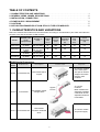
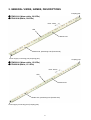
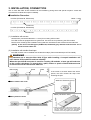
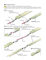
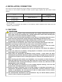
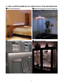
SLIM STICK S-TYPE LED MODULE
APPLICATIONS MANUAL
WARNING
・ Direct LED emission can seriously damage the eyes. Never view a LED emission directly.
・ Never use a disassembled LED module.
・ A LED generates heat while it is emitting.
(The ambient temperature is increased by 20℃
℃ by a 30 LED unit).
Pay attention to avoiding burns and to prevent deformation of the LED mount unit.
INTRODUCTION
This Application Manual is produced for engineers who intend to design lighting items using the Stanley Slim
Stick S-Type LED Modules.
Through the use of this Application Manual, the lighting items can use their unique characteristics effectively.
Safety precautions and notes on the necessary quality conditions for design are described in this manual.
Before the LED lighting item is designed, be sure to read this manual thoroughly and understand the
functions of LED modules.
For performance and quality specifications of LED modules, refer to specifications (separately supplied).
SPECIAL FEATURES OF SLIM STICK S-TYPE LED MODULE
The Stanley Slim Stick S-Type is a unique brand-new LED illumination module which has the special
characteristics described below.
・
・
・
・
・
The thin and narrow stick shape of the LED module is applicable to illumination installed in the narrow spaces.
Emission color can be selected from either warm white or normal white.
Two LED configurations (15 or 30 LEDs) are available.
The LEDs are aligned in the same pitch.
By using a special connector supplied by BJB, LED modules can be joined and the joined LED module
emits the same pitch.
・ The LED module can operate on 12V DC power supply.
・ The LED luminous intensity and emission color dispersion are minimized by the regulation specified by
Stanley.
・ The Stanley LED Modules all conform to the RoHS Directive.
APPLICABLE LED MODULES
This Application Manual applies to the following Stanley Slim Stick S-Type.
MODEL
EMITTED COLOR
(COLOR TEMPERATURE)
NUMBER OF LEDS
STW0101N
Warm white (3,300K)
30 LEDs (10 mm pitch)
STW0201N
Warm white (3,300K)
15 LEDs (20 mm pitch)
STN0101N
White (5,000K)
30 LEDs (10 mm pitch)
STN0201N
White (5,000K)
15 LEDs (20 mm pitch)
REMARKS
TABLE OF CONTENTS
1. CHARACTERISTICS AND VARIATIONS・・・・・・・・・・・・・・・・・・・・・・・・・・・・・・・・・・・・・・・・・・・・・・・・・・・・・ 1
2. GENERAL VIEWS, NAMES, DESCRIPTIONS ・・・・・・・・・・・・・・・・・・・・・・・・・・・・・・・・・・・・・・・・・・・・・・・ 2
3. INSTALLATION, CONNECTION ・・・・・・・・・・・・・・・・・・・・・・・・・・・・・・・・・・・・・・・・・・・・・・・・・・・・・・・・・・・・・ 3
4. POWER SUPPLY REQUIREMENT・・・・・・・・・・・・・・・・・・・・・・・・・・・・・・・・・・・・・・・・・・・・・・・・・・・・・・・・・・・ 5
5. CAUTIONS ・・・・・・・・・・・・・・・・・・・・・・・・・・・・・・・・・・・・・・・・・・・・・・・・・・・・・・・・・・・・・・・・・・・・・・・・・・・・・・・・・・ 5
6. APPLICATION EXAMPLES OF SLIM STICK S-TYPE LED MODULES ・・・・・・・・・・・・・・・・・・・・・・・ 6
1. CHARACTERISTICS AND VARIATIONS
Select the desired LED module from the table below according to the illumination plan which describes the
emission color and the number of LED modules.
Forward
Central
Luminous
Emitted Color
Forward
Power
Voltage
Illumination
Flux
Number of
Current
Consumption
Model
(Color
TYP
H=0.5m
TYP
LEDs
(mA)
(W)
Temperature)
(V cc)
(lx)
(lm)
Warm white
30 LEDs
STW0101N
12
200
80
45
2.4
(3,300K)
(10 mm pitch)
Warm white
15 LEDs
STW0201N
12
100
40
24
1.2
(20 mm pitch)
(3,300K)
White
30 LEDs
STN0101N
12
200
95
55
2.4
(5,000K)
(10 mm pitch)
White
15 LEDs
STN0201N
12
100
60
29
1.2
(5,000K)
(20 mm pitch)
●BJB Special Connectors
Stanley
Model
STCB1
BJB Part No.
47.302.2001.50
Description
Outside View
・To connect modules
of the same pitch.
・This part is used for
straight connection
between LED
modules.
LED module block
coupler
STCC2
47.342.3001
LED module coupler
w/single wires
STCC1
47.342.2001.50
LED module
connector w/double
wires
Purposes
Approx.
50 mm
・To connect
modules.
・When modules are
separately installed,
a maximum 50 mm
separation distance
is allowable.
・To connect module
and power supply.
1
2. GENERAL VIEWS, NAMES, DESCRIPTIONS
Coupling part
●STW0101N (Warm white, 30 LEDs)
●STN0101N (White, 30LEDs)
Pitch: 10mm
LED
Mount hole
Guide hole, positioning hole (Round hole)
Power supply connecting part (Coupling part)
Coupling part
●STW0201N (Warm white, 15 LEDs)
●STN0201N (White, 15 LEDs)
Pitch: 20mm
LED
Mount hole
Guide hole, positioning hole (Round hole)
Power supply connecting part (Coupling part)
2
3. INSTALLATION, CONNECTION
Two or more Slim Stick S LED modules can be installed by joining them with special couplers. A heat sink
mounted LED module has superior reliability.
●Installation Procedure
Offset : 0.7mm
30 LEDs (STW0101N, STN0101N)
Guide hole
15 LEDs (STW0201N, STN0201N)
Guide hole
(1) Installation with screws
Use M3 bolts (round head diameter < 0.7mm) for mounting LED module.
The LED module is equipped with one guide hole. Use this hole for positioning the LED module.
There are five mounting holes in addition to the guide hole. At least two holes must be secured with bolts.
[NOTE] In the case of 30 LED types (STW0101N, STN0101N), pay attention that the holes' line is
offset from the LEDs' line.
(2) Installation with double-faced tape
The LED modules can be installed with double-faced tape. (Recommended tape: NITTO 5000N)
WARNING
Pay attention not to warp the Slim Stick S-Type while installing. A warped installation will
have shorter LED module life and low reliability.
When the special BJB connector is used for coupling LD modules, a 2mm gap will exist due
to the coupler's thickness. To remedy this, a plate, washer or spacer of 2mm thickness must
be used to mount the LED module with bolt.
Screw
PWB
2mm
BJB coupler
If the screw is secured without the above
spacer, the LED module will warp 2mm
stressing the part.
Washers (Thickness: 2mm)
2mm
●When washers are used:
Plates (Thickness: 2mm)
2mm
●When plates are used:
* When a metal plate is used, the insulator must
be placed between the back of the circuit board
and the metal plate. Apply the appropriate
insulator such as vinyl tape to the metal plate.
3
●Connecting Procedure
The number of connector connections/disconnections must not exceed five.
The connector has a projection for meshing with the LED module and guaranteeing polarity orientation.
Insert the connector properly orientated until a click sounds informing complete insertion into the LED
module.
■Power supplying part
30 LEDs type
(STW0101N, STN0101N)
STCC1
STCC1
Cord (Red)
Cord (Red)
Cord (Black)
15 LEDs type
(STW0201N, STN0201N)
Cord (Black)
■Module coupling part *Use STCC2 or STCB1 for coupling the LED modules.
*Use STCB1 to install the LED modules of the same LED pitch.
●Coupling with STCC2
30 LEDs type
(STW0101N, STN0101N)
15 LEDs type
(STW0201N, STN0201N)
STCC2
30 LEDs type
(STW0101N, STN0101N)
●Coupling with STCB1
STCB1
(Set the flat surface up.)
15 LEDs type
(STW0201N, STN0201N)
4
4. INSTALLATION, CONNECTION
Use a DC12V constant voltage power supply. Stanley recommends the following power supply.
The number of LED modules connected is limited by power supply capacity and LED module contact
capacity.
Model
Recommended Power Supply
Number of LED modules
connected
STW0201N, STN0201N
COSEL PBA15F-12
8
(15 LEDs type)
STW0101N, STN0101N
COSEL PBA15F-12
5
(30 LEDs type)
COSEL PBA30F-12
8
*The aforementioned recommended power supplies have sufficient safe performance. However they are
not PSE certified.
*The number of connectable LED modules can be limited by distance between power supply and LED
module or cable resistance.
5. CAUTIONS
CAUTIONS
(1) Please do not bend when using and storing this unit, anytime. Should this product be
bent, it may crack in the soldering area, causing malfunction. Please check carefully that
there will be no excessive stress on module in usage.
(2) In order to prevent electrostatic breakdown at the time of a mounting, please be sure to
protect from any electrostatic charge within the reassembling production process.
(3) Please advise especially the parts (light emitting diode, resistor, etc.) that are mounted in
the switching, the maintenance, etc. that it does not add too much load.
(4) Please be sure to turn OFF the power source when a mounting and removal of this unit.
(5) When connecting to another unit or power source, do not reverse connect.
(6) In real usage, take care not to allow any conductive touch parts to touch the solder
pattern and component part lead on the surface of Slim Stick S-Type.
(7) Please take measures to dustproof the unit, as any dust etc. will effects the quality of
output.
(8) In this unit, please do not submit to strong impulse or vibration or do not scratch with
sharp things, such as an edged tool.
(9) Please keep the temperature and Moisture during storage + usage within the limits
defined by the specification. Moreover, please avoid usage or storage in any environment
exposed to the organic solvent, etching gas (gaseous chlorine and sulfuration gas), etc.,
or fire.
(10) When cleaning the LED module post installation, use air pressure to blow off dust or
softly wipe with dry cloth to remove dust. Non observance of this caution (such as wiping
with moistened cloth, cleaning with detergent, solvent or alcohol, etc.) will result in LED
lighting failure and/or shorter life.
If the LED modules are installed in an area needing frequent cleaning, cover the LED
modules with a transparent acrylic cover or equivalent.
(11) During real usage, constraints, such as an input voltage, an operating environment, etc.
(temperature and Moisture) defined by the specification, should be observed. If used
outside of specification, the unit may not be able to satisfy optical and the electric
characteristics defined by the specification.
(12) The characteristics described in this specifications may be altered without previous
notice in order to improve the performance.
5
6. APPLICATION EXAMPLES OF SLIM STICK S-TYPE LED MODULES
■Bed side illumination
■Ambient illumination (Indirect lighting)
■Under counter illumination
■Cabinet illumination
6