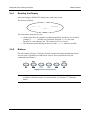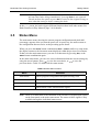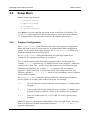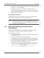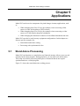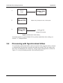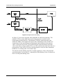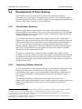
1
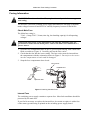
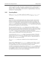
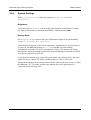
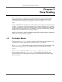
Model 585 Time Scaling Processor Issue 2 Part Number 91796 Model 585 Time Scaling Processor Dolby Laboratories, Inc. Corporate Headquarters Dolby Laboratories, Inc. 100 Potrero Avenue San Francisco, CA 94103-4813 Telephone 415-558-0200 Fax 415-863-1373 www.dolby.com European Headquarters Dolby Laboratories, Inc. Wootton Bassett Wiltshire, SN4 8QJ, England Telephone (44) 1793-842100 Fax (44) 1793-842101 DISCLAIMER OF WARRANTIES: EQUIPMENT MANUFACTURED BY DOLBY LABORATORIES IS WARRANTED AGAINST DEFECTS IN MATERIALS AND WORKMANSHIP FOR A PERIOD OF ONE YEAR FROM THE DATE OF PURCHASE. THERE ARE NO OTHER EXPRESS OR IMPLIED WARRANTIES AND NO WARRANTY OF MERCHANTABILITY OR FITNESS FOR A PARTICULAR PURPOSE, OR OF NONINFRINGEMENT OF THIRD-PARTY RIGHTS (INCLUDING, BUT NOT LIMITED TO, COPYRIGHT AND PATENT RIGHTS). LIMITATION OF LIABILITY: IT IS UNDERSTOOD AND AGREED THAT DOLBY LABORATORIES’ LIABILITY, WHETHER IN CONTRACT, IN TORT, UNDER ANY WARRANTY, IN NEGLIGENCE, OR OTHERWISE SHALL NOT EXCEED THE COST OF REPAIR OR REPLACEMENT OF THE DEFECTIVE COMPONENTS OR ACCUSED INFRINGING DEVICES, AND UNDER NO CIRCUMSTANCES SHALL DOLBY LABORATORIES BE LIABLE FOR INCIDENTAL, SPECIAL, DIRECT, INDIRECT, OR CONSEQUENTIAL DAMAGES, (INCLUDING, BUT NOT LIMITED TO, DAMAGE TO SOFTWARE OR RECORDED AUDIO OR VISUAL MATERIAL), COST OF DEFENSE, OR LOSS OF USE, REVENUE, OR PROFIT, EVEN IF DOLBY LABORATORIES OR ITS AGENTS HAVE BEEN ADVISED, ORALLY OR IN WRITING, OF THE POSSIBILITY OF SUCH DAMAGES. Dolby and the double-D symbol are registered trademarks of Dolby Laboratories. All other trademarks remain the property of their respective owners. 2003 Dolby Laboratories, Inc. All rights reserved. Part Number 91796 Issue 2 S03/14154/14618 ii Model 585 Time Scaling Processor Table of Contents List of Figures................................................................................................................ v List of Tables ................................................................................................................. v Regulatory Notices ....................................................................................................... vi Fusing Information ...................................................................................viii Chapter 1 Introduction ...........................................................................................1-1 Chapter 2 Getting Started ......................................................................................2-1 2.1 Unpacking and Inspection ............................................................2-1 2.2 Installing .......................................................................................2-1 2.3 Rear Panel ...................................................................................2-2 2.3.1 Digital Audio Connections ................................................2-2 2.3.2 Serial Connection Ports....................................................2-3 2.3.3 Remote Connection Ports ................................................2-4 2.4 Front Panel...................................................................................2-4 2.4.1 Reading the Display .........................................................2-5 2.4.2 Buttons .............................................................................2-5 2.4.3 Knob .................................................................................2-6 2.5 Status Menu .................................................................................2-7 2.6 Setup Menu ..................................................................................2-8 2.6.1 Program Configuration .....................................................2-8 2.6.2 Operating Mode................................................................2-9 2.6.3 System Settings .............................................................2-11 Chapter 3 Time Scaling ..........................................................................................3-1 3.1 Transport Menu ............................................................................3-1 3.1.1 Play ..................................................................................3-2 3.1.2 Record..............................................................................3-5 3.1.3 Program Selection ............................................................3-5 3.2 Time Scaling of Longer Programs ................................................3-6 Chapter 4 Pitch Shifting .........................................................................................4-1 4.1 Adjusting the Pitch Shifting Value.................................................4-1 4.2 Using Pitch Shifting to Perform Online Time Scaling....................4-2 Chapter 5 Applications...........................................................................................5-1 5.1 Stand-Alone Processing ...............................................................5-1 5.2 Processing with Synchronized Video............................................5-2 iii Model 585 Time Scaling Processor Chapter 6 Principles of Operation.........................................................................6-1 6.1 Multichannel Delivery ...................................................................6-1 6.2 Development of Time Scaling.......................................................6-2 6.2.1 Time-Domain Solutions ....................................................6-2 6.2.2 Frequency-Domain Solutions ...........................................6-2 6.2.3 Modeling-Based Solutions................................................6-3 6.2.4 Choosing a Solution .........................................................6-3 6.3 Intelligent Analysis........................................................................6-3 Chapter 7 Reference Data ......................................................................................7-1 7.1 Channel Mapping .........................................................................7-1 7.2 Specifications ...............................................................................7-2 iv Model 585 Time Scaling Processor List of Figures Figure 1 Checking the Main Fuse..................................................................................viii Figure 2-1 Connections: Signal In and Out...................................................................2-2 Figure 2-2 Connections: Remote RS-232, GP I/O, Metadata In and Out .....................2-3 Figure 2-3 Model 585 Front Panel ................................................................................2-4 Figure 2-4 Front-Panel Buttons ....................................................................................2-5 Figure 5-1 Stand-Alone Time Scaling ...........................................................................5-2 Figure 5-2 Single-Pass Pitch Shifting ...........................................................................5-3 List of Tables Table 2-1 Front-Panel Button Definitions......................................................................2-6 Table 2-2 Status Menu Screens ...................................................................................2-7 Table 3-1 Play Menu Button Mapping ..........................................................................3-2 Table 7-1 Channel Mapping according to Program Configuration ................................7-1 v Model 585 Time Scaling Processor Regulatory Notices USA This equipment has been tested and found to comply with the limits for a Class A digital device, pursuant to Part 15 of the FCC Rules. These limits are designed to provide reasonable protection against harmful interference when the equipment is operated in a commercial environment. This equipment generates, uses, and can radiate radio frequency energy and, if not installed and used in accordance with this instruction manual, may cause harmful interference to radio communications. Operation of this equipment in a residential area is likely to cause harmful interference in which case the user will be required to correct the interference at his or her own expense. WARNING: Troubleshooting must be performed by a trained technician. Do not attempt to service this equipment unless you are qualified to do so. Check that the correct fuses have been installed. To reduce the risk of fire, replace only with fuses of the same type and rating. Exposed portions of the power supply assembly are electrically “hot.” To reduce risk of electric shock, the power cord must be disconnected when the power supply assembly is removed. The ground terminal of the power plug is connected directly to the chassis of the unit. For continued protection against electric shock, a correctly wired and grounded (earthed) threepin power outlet must be used. Do not use a ground-lifting adapter and never cut the ground pin on the three-prong plug. WARNING: Before applying power, check the main fuse using the procedure on page viii. Canada This Class A digital apparatus complies with Canadian ICES-003. EU This equipment complies with the EMC requirements of EN55103-1 and EN55103-2 when operated in an E2 environment in accordance with this manual. UK Use power cord Dolby part number 92031 supplied with unit (pre-fitted with 13A plug to BS1363) to connect Model 585 to the mains supply. This equipment must be earthed. vi Model 585 Time Scaling Processor IMPORTANT SAFETY NOTICE This unit complies with the safety standard EN60065. The unit shall not be exposed to dripping or splashing and no objects filled with liquids, such as coffee cups, shall be placed on the equipment. To ensure safe operation and to guard against potential shock hazard or risk of fire, the following must be observed: o Ensure that your mains supply is in the correct range for the input power requirement of the unit. GB o Ensure fuses fitted are the correct rating and type as marked on the unit. o The unit must be earthed by connecting to a correctly wired and earthed power outlet. o The power cord supplied with this unit must be wired as follows: Live—Brown Neutral—Blue Earth—Green/Yellow IMPORTANT – NOTE DE SECURITE Ce materiel est conforme à la norme EN60065. Ne pas exposer cet appareil aux éclaboussures ou aux gouttes de liquide. Ne pas poser d'objets remplis de liquide, tels que des tasses de café, sur l'appareil. Pour vous assurer d'un fonctionnement sans danger et de prévenir tout choc électrique ou tout risque d'incendie, veillez à observer les recommandations suivantes. F o Le selecteur de tension doit être placé sur la valeur correspondante à votre alimentation réseau. o Les fusibles doivent correspondre à la valeur indiquée sur le materiel. o Le materiel doit être correctement relié à la terre. o Le cordon secteur livré avec le materiel doit être cablé de la manière suivante: Phase—Brun Neutre—Bleu Terre—Vert/Jaune WICHTIGER SICHERHEITSHINWEIS Dieses Gerät entspricht der Sicherheitsnorm EN60065. Das Gerät darf nicht mit Flüssigkeiten (Spritzwasser usw.) in Berührung kommen; stellen Sie keine Gefäße, z.B. Kaffeetassen, auf das Gerät. Für das sichere Funktionieren des Gerätes und zur Unfallverhütung (elektrischer Schlag, Feuer) sind die folgenden Regeln unbedingt einzuhalten: o Der Spannungswähler muß auf Ihre Netzspannung eingestellt sein. D o Die Sicherungen müssen in Typ und Stromwert mit den Angaben auf dem Gerät übereinstimmen. o Die Erdung des Gerätes muß über eine geerdete Steckdose gewährleistet sein. o Das mitgelieferte Netzkabel muß wie folgt verdrahtet werden: Phase—braun Nulleiter—blau Erde—grün/gelb NORME DI SICUREZZA – IMPORTANTE Questa apparecchiatura è stata costruita in accordo alle norme di sicurezza EN60065. Il prodotto non deve essere sottoposto a schizzi, spruzzi e gocciolamenti, e nessun tipo di oggetto riempito con liquidi, come ad esempio tazze di caffè, deve essere appoggiato sul dispositivo. Per una perfetta sicurezza ed al fine di evitare eventuali rischi di scossa êlettrica o d'incendio vanno osservate le seguenti misure di sicurezza: o Assicurarsi che il selettore di cambio tensione sia posizionato sul valore corretto. o Assicurarsi che la portata ed il tipo di fusibili siano quelli prescritti dalla casa costruttrice. I o L'apparecchiatura deve avere un collegamento di messa a terra ben eseguito; anche la connessione rete deve avere un collegamento a terra. o Il cavo di alimentazione a corredo dell'apparecchiatura deve essere collegato come segue: Filo tensione—Marrone Neutro—Blu Massa—Verde/Giallo AVISO IMPORTANTE DE SEGURIDAD Esta unidad cumple con la norma de seguridad EN60065. La unidad no debe ser expuesta a goteos o salpicaduras y no deben colocarse sobre el equipo recipientes con liquidos, como tazas de cafe. Para asegurarse un funcionamiento seguro y prevenir cualquier posible peligro de descarga o riesgo de incendio, se han de observar las siguientes precauciones: o Asegúrese que el selector de tensión esté ajustado a la tensión correcta para su alimentación. E o Asegúrese que los fusibles colocados son del tipo y valor correctos, tal como se marca en la unidad. o La unidad debe ser puesta a tierra, conectándola a un conector de red correctamente cableado y puesto a tierra. o El cable de red suministrado con esta unidad, debe ser cableado como sigue: Vivo—Marrón Neutro—Azul Tierra—Verde/Amarillo VIKTIGA SÄKERHETSÅTGÄRDER Denna enhet uppfyller säkerhetsstandard EN60065. Enheten får ej utsättas för yttre åverkan samt föremål innehållande vätska, såsom kaffemuggar, får ej placeras på utrustningen." För att garantera säkerheten och gardera mot eventuell elchock eller brandrisk, måste följande observeras: o Kontrollera att spänningsväljaren är inställd på korrekt nätspänning. S o Konrollera att säkringarna är av rätt typ och för rätt strömstyrka så som anvisningarna på enheten föreskriver. o Enheten måste vara jordad genom anslutning till ett korrekt kopplat och jordat el-uttag. o El-sladden som medföljer denna enhet måste kopplas enligt foljande: Fas—Brun Neutral—Blå Jord—Grön/Gul BELANGRIJK VEILIGHEIDS-VOORSCHRIFT Deze unit voldoet aan de EN60065 veiligheids-standaards. Dit apparaat mag niet worden blootgesteld aan vocht. Vanwege het risico dat er druppels in het apparaat vallen, dient u er geen vloeistoffen in bekers op te plaatsen. Voor een veilig gebruik en om het gevaar van electrische schokken en het risico van brand te vermijden, dienen de volgende regels in acht te worden genomen: o Controleer of de spanningscaroussel op het juiste Voltage staat. NL o Gebruik alleen zekeringen van de aangegeven typen en waarden. o Aansluiting van de unit alleen aan een geaarde wandcontactdoos. o De netkabel die met de unit wordt geleverd, moet als volgt worden aangesloten: Fase—Bruin Nul—Blauw Aarde—Groen/Geel vii Model 585 Time Scaling Processor Fusing Information WARNING: To reduce the risk of fire, replace fuses only with the same type and rating. The unit uses a universal switching power supply that handles the full range of nominal mains voltages between 90 and 264 VAC and any frequency between 50 and 60 Hz. Check Main Fuse The Main fuse rating is: T 1A L (1 Amp, 250 V, 20 mm, time-lag, low-breaking capacity) for all operating voltages. WARNING: The power to the unit must be off when the following steps are performed. Ensure that the main power cable to the unit is not connected to a power source. 1. Open the fuse compartment door in the AC power input housing with a small flatblade screwdriver (Figure 1). Carefully pull out the fuse carrier. 2. Check that the fuse has the correct rating. The fuse carrier must be inserted into the compartment with the orientation shown in Figure 1. Do not force the carrier into the compartment or both could be damaged. 3. Snap the fuse compartment door closed. Fuse carrier Installed fuse Open the door Figure 1 Checking the Main Fuse Internal Fuse The switching power supply contains a separate fuse. Most fault conditions should be protected by the main fuse. If you find it necessary to replace the internal fuse, be certain to replace it with a fuse of the same type and rating as printed on the switching power supply board. viii Model 585 Time Scaling Processor Chapter 1 Introduction The Model 585 Time Scaling Processor delivers true time scaling and pitch shifting for the studio professional. A change in the playback speed of analog tape—or in the sample playback rate for digital formats—has always brought about a change in the audio pitch as well as the duration of the audio program being played. However, this fixed link between playback speed and pitch has often meant a compromise in audio quality. Therefore, the ability to precisely determine and alter pitch and program duration independently has been a necessity since it first became possible to alter the speed of a recording. Today, many standard operations result in a change in audio pitch; for example, when converting a film for broadcast at 25 fps, or adjusting a program’s length to match the available broadcast time slot. There have been attempts over the years to provide pitch shifting and time scaling. Early products showed glaring weaknesses, and more recent attempts have tended to be useful only on a limited range of material. Model 585 delivers dependable processing of any signal, across the whole spectrum of audio: music, speech, special effects, and any combination of these elements. Multichannel Delivery Model 585 is the first product to deliver truly phase-synchronous time scaling and pitch shifting for multiple (up to eight) channels of audio—something multiple stereo processors cannot achieve. It is important to preserve the phase relationship of multichannel audio programs for all listeners; it is especially important for those with stereo or mono reproduction equipment, who hear a summing of the multichannel elements. Model 585 is compatible with all Dolby® E products. Real-Time Time Scaling and Pitch Shifting Model 585 delivers two separate functions: time scaling and pitch shifting. Each function can be applied in real time. Time scaling alters the duration of an audio signal but leaves the perceived pitch unchanged from the original signal. Time scaling and how to implement it using Model 585 is discussed in Chapter 3. 1-1 Model 585 Time Scaling Processor Introduction Pitch shifting, sometimes referred to in other documents as pitch scaling, alters the perceived frequency of the audio signal from that of the original signal, while leaving the duration of the signal the same as the original. Pitch shifting and its implementation using Model 585 is covered in Chapter 4. 1-2 Model 585 Time Scaling Processor Chapter 2 Getting Started This chapter covers connection requirements for Model 585 and the basics of using the front-panel controls. 2.1 Unpacking and Inspection Before unpacking Model 585, inspect the outer carton for shipping damage. If the carton shows damage, inspect Model 585 in the associated areas. The BNC connectors on the rear panel are covered with protective plastic caps. The following items are provided with Model 585: • • • 2.2 Three power cords: one each for US, continental Europe, and the UK. Use the cord appropriate to your location. A bag containing rackmount screws and washers, plus five 75Ω BNC terminators. Warranty information. Fill out the warranty card and return to Dolby Laboratories. To receive software upgrades, register your product on the software upgrades page at www.dolby.com/download/softreg. Installing Installing Model 585 requires: • • Two standard rackspace units. Digital I/O. The digital input and output connections on Model 585 may be unfamiliar to a first-time user of a digital audio device. The Audio Engineering Society (AES) created a standard electrical interface for digital audio with a balanced XLR connector and 110Ω impedance called AES31995. This interface was later expanded to include an unbalanced BNC connector, 1 Vp–p signal level, and 75Ω impedance; it is now known as both AES3-ID-1995 and SMPTE-276M. Model 585 uses this new standard for digital audio electrical interface connections. Note: These signals must be properly terminated with a 75Ω impedance at one point only. We recommend a standard video terminator. 2-1 Model 585 Time Scaling Processor • • Getting Started Cables. We recommend standard 75Ω BNC cables for digital audio signal connections. To connect to digital equipment with 110Ω XLR connectors, use impedance-matching transformers (readily available from Canare, Neutrik, and other manufacturers). Input channel 1/2 must be connected to a valid digital audio signal for proper operation of the unit. Model 585 can be used between any two products that carry PCM audio. For specific installation examples, see Chapter 5, Applications. 2.3 Rear Panel The main fuse rating is: T 1A L (1 amp, 250 V, 20 mm, time-lag, low-breaking capacity) for all operating voltages. WARNING: Before applying power, check the main fuse, using the procedure on page viii. There is no power switch on Model 585. To apply power, connect the power cord to a live outlet. 2.3.1 Digital Audio Connections Figure 2-1 shows the digital audio input and output connections. 1 3 Ch 1/2 Ch 3/4 Ch 1/2 Ch 3/4 Digital Inputs Ch 5/6 Ch 7/8 Ch 5/6 Ch 7/8 Digital Outputs Figure 2-1 Connections: Signal In and Out 2-2 AES Ref 2 Model 585 Time Scaling Processor Getting Started Figure 2-1 definitions: 1. Digital Inputs. Model 585 requires PCM audio input at a sample rate of 48 kHz ± 15%. Each input has two connectors; either connector can be used for the input or as a loop-through for that channel pair. If the loop-through connection is not being used, it must be fitted with a 75Ω termination. The last device in the loop-through signal chain must be terminated with 75Ω. Note: Ch 1/2 requires a valid PCM digital audio signal. That input is used to derive the clocks for all input channels and is the reference clock for scaling. 2. AES Ref. Connect to an AES digital audio reference source. The second connector can either be used as a loop-through or be terminated, as appropriate. Note: AES Ref requires a valid AES digital audio signal. That input is used to derive the clocks for all output channels and so is the reference clock for the digital outputs. 3. Digital Outputs. These connections carry the processed PCM signal. 2.3.2 Serial Connection Ports Figure 2-2 shows the serial connection ports. 1 2 Remote RS-232 Metadata In 4 3 GP I/O Metadata Out Figure 2-2 Connections: Remote RS-232, GP I/O, Metadata In and Out Figure 2-2 definitions: 1. Remote RS-232. Connect to this port to update Model 585 software. 2. Metadata In. (Reserved for future use.) Input port for external metadata. Connect to a device that delivers Dolby® metadata, such as a Dolby E decoder or Model DP570 Multichannel Audio Tool. 3. GP I/O. This port provides a fixed, TTL level-sensitive output indicating the current status of Model 585. 4. Metadata Out. (Reserved for future use.) Output port for metadata. Connect to a downstream Dolby E or Dolby Digital encoder. 2-3 Model 585 Time Scaling Processor 2.3.3 Getting Started Remote Connection Ports The Remote (9-pin) In and Remote (9-pin) Out ports are reserved for future enhancements. 2.4 Front Panel The front panel is shown with feature definitions in Figure 2-3. Knob for adjustment of settings and menu navigation Menu display shows the current function mode LEDs indicate when specific modes are in use Buttons for menu navigation, function selection, and adjustment of settings Figure 2-3 Model 585 Front Panel The menu system has two independent structures: setup and status. The setup menu lets you control and configure Model 585 to suit your requirements. The status menu displays information regarding the operating status. There are two ways to adjust settings on Model 585. All functions are adjustable using the buttons below the display window, and some functions can be easily adjusted using the knob. 2-4 Model 585 Time Scaling Processor 2.4.1 Getting Started Reading the Display After powering up, Model 585 displays the main status menu. The factory default is: 5.1 + 2 Sens=5 +0.0 The main status menu shows you: 2.4.2 • On the upper line, the program configuration and the sensitivity level. In this example, 5.1 + 2 defines two programs: Program 1, a 5.1 mix; and Program 2, a two-channel mix. The sensitivity level is set to 5. • The amount of pitch shifting on the lower line, +0.0%, indicates no shift. Buttons The six buttons in Figure 2-4 display window control navigation through the menus and selection of parameters within menu screens. Press any button to use the command listed below it. Status Shift Bypass Setup Enter Esc Figure 2-4 Front-Panel Buttons Note: In the Transport menu, some buttons are redefined to trigger functions not available in all other menus. For more details, see Section 3.1, Transport Menu. 2-5 Model 585 Time Scaling Processor Getting Started Table 2-1 Front-Panel Button Definitions Button Result Shift Selects the alternate function for a button. To select Status or Bypass, hold down Shift and press the button under the selection you want. Setup From any status menu, displays the last setup menu viewed, or the Unit Setup menu if a setup menu has not been viewed in the previous five minutes. From any setup menu, displays the Unit Setup menu. Status From any setup menu, displays the last status menu viewed, or the main status menu if a status menu has not been viewed in the previous five minutes. From any status menu, displays the main status menu (program configuration and amount of pitch shift). Scrolls to previous item in menu selection display. In menus that determine a numeric value, increases that value. Scrolls to next item in menu selection display. In menus that determine a numeric value, decreases that value. Enter Esc Bypass Activates the menu or setting on the lower line of the display. Reverts to the next-higher menu level, or if the active setting is different from the setting on screen, returns the display to the active setting. Activates bypass mode. Processing latency remains in effect, but no adjustments are made to the output signal. To take the unit out of bypass mode, press Shift + Bypass again. Note: In all menus, settings other than the active one display a flashing block next to the setting. Press Enter to select the setting shown, or Esc to return to the active setting. 2.4.3 Knob The knob offers quick adjustment of many menu options. Rotating clockwise scrolls through setup menu options in the same way as pressing . Rotating counterclockwise scrolls through setup menu options in the same way as pressing . In the main status menu, you can adjust the pitch shift value by turning the knob. Pressing Shift while turning the knob changes the sensitivity level. Pressing either arrow button scrolls to other status menu displays. 2-6 Model 585 Time Scaling Processor Getting Started Caution: Adjusting the pitch shift value or sensitivity level in the main status menu activates that value change immediately; pressing Enter is not required. You do not have the option to press Esc to return to the original setting, so note what that setting is before rotating the knob. In the Play menu, the knob triggers different functions than in all other menus. See Knob Function in Play Menu on page 3-4 for details. 2.5 Status Menu The main status menu, showing the current program configuration and pitch shift percentage, appears when you turn the power on. At power-up, the status returns to the configuration that was active at the preceding power-down. When you press the Status button combination (Shift + Status) while in a setup menu, the display returns to the last status menu displayed within the previous five minutes. If that is not the main status menu, you can view that menu by pressing Esc, or the Status button combination again. In the main status menu, you can view more information about the current settings by using the arrow buttons. Press to view the next choice, or to view the previous choice. Table 2-2 defines all the status menus. Table 2-2 Status Menu Screens Menu Main Status Definition Shows program configuration and pitch shifting value. Firmware Version Shows version number of firmware loaded on Model 585. Digital In Enter to see status of the input signal for each channel pair. Reference In Shows status of the AES Reference signal. Note: There is no indication of the condition of the reference or digital input signals on the front panel or the main status menu. The status of these signals is only available through the individual status menus. 2-7 Model 585 Time Scaling Processor 2.6 Getting Started Setup Menu Options in the setup menu are: • Program Config • Operating Mode • Transport • System Settings Press Enter to view the menu for the option on the second line of the display. The Transport menu operates the time scaling function, and is described in Section 3.1, Transport Menu. The other three menus are described in this section. 2.6.1 Program Configuration The Program Config menu initially displays the active program configuration. Rotate the knob or press an arrow button to scroll through the other configuration options. To process the input signal properly, the Program Config setting must match the configuration of the input signal. The Program Config setting describes how the eight input channels are configured. The notation conventions are as follows: The + symbol separates individual audio programs within a configuration. For example, 5.1 + 2 represents one 5.1-channel and one stereo program—which may or may not be related. The × symbol shows the number of a given channel format within that configuration. For example, 4 × 2 represents four two-channel programs—again, which may or may not be related. One configuration has four different programs: 4 + 2 + 2 × 1, which is one four-channel, one two-channel, and two mono programs. The Program Config parameter instructs Model 585 which input channels to process together as a single, phase-coherent program. For example: 5.1 Processes the first six input channels as one complete 5.1-channel audio program. 5.1 + 2 Processes the first six input channels as one complete 5.1-channel audio program. Processes channels 7 and 8 as one complete stereo program. 4 × 2 Processes channel pairs 1/2, 3/4, 5/6, and 7/8 as four separate stereo programs. Model 585 processes all program configurations to the same high quality. Therefore, there is no difference in audio performance between 2 + 2, 3 × 2, or 4 × 2 program configurations. 2-8 Model 585 Time Scaling Processor Getting Started Channel assignments within each program configuration follow standard mapping, as shown in Table 7-1 in Chapter 7, Reference Data. The only exception is the lowfrequency effects (LFE) channel, which can also be assigned manually, as described in Section 2.6.2, Operating Mode. 2.6.2 Operating Mode In the Operating Mode menu, you have six options: Sensitivity, Pitch, Processing Delay, Clock Source, DC Filter, and LFE Channel. Sensitivity Model 585 is able to perform high-quality time scaling of complex audio material because, in a manner comparable to that used by human listeners, it analyzes and identifies the individual audio components and processes them independently. The Sensitivity setting allows you to adjust the level of processing detail Model 585 applies to the audio material. The default setting, 5–high, provides the most detailed processing and is appropriate for nearly all material. For some material, however, the 5–high setting may be too sensitive, causing Model 585 to focus on subtle audio elements that can interfere with the processing of the most prominent material. In this case, Model 585 may not produce its best results. For example, if material with a live audience is being processed and the Sensitivity setting is too high, Model 585 may focus on elements of audience or ambient sounds to the detriment of the primary audio material. As you decrease the Sensitivity setting, less prominent elements of the audio material are processed less intensively, reducing the impact on the most prominent elements. If the Sensitivity setting is too low, however, important elements of the audio may not be processed correctly. The Sensitivity setting can be adjusted in real time using the front-panel controls. If you alter the setting using the Sensitivity submenu, you are able to “cue up” different settings. For example, you can be processing audio at one setting, select a new setting and then press enter to activate the new setting as required. In addition to adjusting this setting directly within the Sensitivity submenu, you can also make the adjustment from the main status menu by rotating the knob while pressing Shift. If you do so, however, the adjustment is immediately activated, and you cannot return to the previous value by pressing Esc. 2-9 Model 585 Time Scaling Processor Getting Started Note: Sensitivity should remain at 5–high for most program material. If the setting must be changed, the change should be limited to the length of the specific passage that requires the change, and then returned to 5–high. Setting changes activate in real time when changed using the front-panel controls. Pitch You can use the Pitch menu to select a new scaling value by pressing the arrow buttons or rotating the knob. You can also make this adjustment from the main status menu by rotating the knob. If you do so, however, the adjustment is immediately activated, and you cannot return to the previous value by pressing Esc. Processing Delay The Processing Delay menu defines the system latency in milliseconds, within a range of 400–480 ms. The default is 440 ms. Clock Source In the Clock Source menu, you can choose the source for the digital audio output clock. The default is Digital Input, which locks the output clock to the channel 1/2 input. Internal 48 kHz locks the output clock to an internal 48 kHz oscillator. External Ref-In locks the output clock to the AES Ref input clock. The status of the AES Ref input clock is displayed in the Reference In status menu. DC Filter The DC Filter can be turned on to eliminate any inconsistency due to the processing of very low frequency or subsonic sounds. The default is Disabled. LFE Channel In the LFE Channel menu, you can adjust the assignment of the LFE channel to match the input. The factory default is Auto, which assigns all channels according to the standard channel mapping shown in Table 7-1. If the input to Model 585 includes a program with an LFE channel assignment not in line with the assignments in Table 7-1, you need to assign the LFE channel manually using this menu. In multichannel audio, the LFE channel is bandwidth-limited, so to process the complete program audio properly, the LFE channel must be assigned correctly. 2-10 Model 585 Time Scaling Processor 2.6.3 Getting Started System Settings In the System Settings menu, the options are Display Mode and Brightness. Brightness You can use the Brightness menu to adjust the intensity of the display. Changes you make in this menu are activated immediately, without pressing Enter. Display Mode Use Display Mode to choose the unit of adjustment displayed for pitch shifting: frames, ¢ (cents), or % (percent). Frame mode uses percent as the unit of adjustment. Adjustments are in increments of 0.1 percent. An additional setting of +4.17% is included, for pitch shifting presentations recorded at 25 fps but played back at 24 fps. The frame mode display also indicates when the setting is appropriate for pitch shifting presentations recorded at 24 fps but played back at 25 fps. Cents represent musical cents, where 100 cents equals one semitone, and 1,200 cents equals one octave. Model 585 offers a shifting range of –282 to +242 cents. Percent mode operates in the same manner as frame mode in all but two ways: it lacks the additional +4.17% setting, and does not indicate the values appropriate for conversions between frame rates. 2-11 Virtual Dolby Technologies Test DVD Track List iv Model 585 Time Scaling Processor Chapter 3 Time Scaling Time scaling alters the duration of an audio signal, but leaves the perceived pitch unchanged from the original signal. Model 585 offers stand-alone, high-quality multichannel time scaling of short program segments by using the Transport menu. At the standard 48 kHz sampling rate, Model 585 can store approximately 23 minutes of mono, 11.5 minutes of stereo, 6 minutes of four-channel, 4 minutes of 5.1-channel, or almost 3 minutes of eight-channel audio material. If the sampling rate changes, the storage capacity changes inversely: for example, a ten-percent reduction in sampling rate gives a ten-percent increase in storage capacity. Model 585 also can be used in combination with other products to deliver continuous, online time scaling of longer programs. 3.1 Transport Menu You can use the Transport menu to record an audio clip to internal memory and play back the clip time scaled at a rate within a range of ±15 percent. In the Transport menu, the front-panel controls perform different tasks than in all other menus. This gives you access to the separate set of controls time scaling requires. The Transport menu includes Play, Record, and Program Select menus. Entering either the Play or Record menu disables pitch shifting and reconfigures the four center buttons to trigger the function illustrated on the display above the button. 3-1 Model 585 Time Scaling Processor 3.1.1 Time Scaling Play Enter the Play menu to manipulate the time scaling of the clip stored in memory, or to simply play the clip, or any part of it. When you enter the Play menu, you see: ■ ■ /► 00:00.00 % In Out Status Setup Enter The upper line shows the transport status, the point in the stored clip where you last viewed the menu, and a clock symbol. When you enter the play menu, the transport status is in stop mode, as shown here. If you have not yet played any of the clip, the display reads 00:00.00, as shown here. The clock symbol is there simply to remind you that Model 585 is in time scaling mode. Note: The time displayed represents the scaled time value according to the current scaling percentage. If you change the scaling percentage, the time value changes accordingly. The four center front-panel buttons are mapped to the functions displayed on the lower line of the display, as shown in Table 3-1. More details on button functions follow the table under the heading of each mapped function. Knob operation is also detailed. Table 3-1 Play Menu Button Mapping Button Play Menu Function Setup Stop/Play Stops/Starts playback of clip in internal memory. Scaling Percentage Enters the % menu, where you can adjust the scaling of the clip. In Point Enter Out Point Result Moves the clip to the saved In point. To set the In point, press Shift + . Moves the clip to the saved Out point. To set the Out point, press Shift + Enter. 3-2 Model 585 Time Scaling Processor Time Scaling When a clip is stored in the Model 585 memory, the Play menu displays the scaled time value of that clip. If you change the scaling percentage, the length of the scaled clip changes to reflect that, and the Play menu display, In point, and Out point all update accordingly. Stop/Play In the Play menu, Setup acts as a Stop/Play toggle. When you enter the Play menu, Model 585 is in stop mode. When you press Setup in stop mode, playback of the clip starts. If no In point or Out point has been set, playback starts at the current transport position and continues until you press Setup again, or until the clip ends. When the clip ends, stop mode reactivates. When an In point or Out point is set, the Stop/Play command functions as described under those headings in this section. Scaling Percentage When you enter the % menu, you see: Orig. +10.0% 00:30.00 00:33.00 Status Setup Enter The screen values shown here are only an example. The upper line shows the length of the original clip. The second line shows the scaling percentage and the resulting length of the scaled clip. You can adjust the scaling percentage in this menu using the arrow buttons, or by rotating the knob. As you change the scaling percentage, the display for the length of the scaled clip updates. Scaling changes are applied immediately in this menu. If you are playing a clip, it continues playing at the new scaling percentage. Note: You can only exit the Scaling Percentage menu by pressing Esc. If you select Bypass, playback stops. 3-3 Model 585 Time Scaling Processor Time Scaling In Point The In point is the point in the audio clip when playback starts. If the transport position is at or before the In point when you press Play, playback begins at the In point. When the transport is at the In point, the display shows a dot before the word In: ·In. To set or reset the In point to the current transport position, press Shift + set the In point in either play or stop mode. . You can Note: If you need to reset the In point to a point earlier than the current In point, rotate the knob to move to a transport position before the In point and press Shift + to reset the In point. Out Point The Out point is the point in the audio clip when playback ends. If the transport position is beyond the Out point when you press play, playback starts at that transport position and continues until the end of the clip, or until you stop playback. When the transport is at the Out point, the display shows a dot before the word Out: ·Out. When the transport is at the Out point, pressing play does not start playback. To set or reset the Out point in the current clip, press Shift + Enter. Knob Function in Play Menu In the Play menu, you can use the knob to adjust the transport position in the recorded clip. As you move through the clip, the time display updates to show your position in the recorded clip. There are two ways to use the knob to adjust the transport position: rotating the knob by itself, and rotating the knob while holding down Shift. When you rotate the knob by itself, the display shows or and a number indicating how fast you are moving through the clip. This rate reflects how fast you rotate the knob. This mode makes it easy to move short distances or locate a specific point in the clip. When you stop rotating the knob, the transport returns to stop mode. When you hold down Shift while rotating the knob, you move through the clip according to the position of the knob compared to its position when you begin holding down Shift. In this mode, the display shows « or » and a number indicating how fast you are moving through the clip. Moving the knob 120° in either direction from the initial position brings you to the beginning or end of the clip. While in this mode, the audio level is lowered by 6 dB. The audio level returns to normal after the transport has stopped. Once you move the knob, as long as you hold the Shift button you continue to move at the speed and direction set by the position of the knob. When 3-4 Model 585 Time Scaling Processor Time Scaling you release Shift, the transport returns to stop mode at the position in the clip when you release Shift. Holding Shift makes it particularly easy to move through the clip rapidly, but it also allows you to move slowly at a steady pace, without having to manually turn the knob. 3.1.2 Record When you enter the Record menu, you see: ■ ■ /z 00:00.00 P1 Status Setup Enter In this menu, the Setup button is a Stop/Record toggle. When you start a recording, the previous recording is erased, and the previous In point and Out point settings are cleared. During recording, the top line displays z and the elapsed recording time. When you stop a recording, the top line displays ■ and the total time of the clip just recorded. If you reach the maximum recording time, recording stops automatically. Pressing Esc stops the recording and exits the Record menu. Selecting Bypass while in record mode stops the recording. 3.1.3 Program Selection If the program configuration includes more than one program, use the Program Select menu to select the appropriate program to record. For a complete list of program configurations and the associated program numbers and channel assignments, see Table 7-1. The second line in the Record menu displays which program records. In the example shown in Section 3.1.2, Record, P1 indicates that Program 1 will record. If the current program configuration includes more than one program, you can record any one of the programs or all the programs. For example, the 5.1 + 2 configuration contains two programs; you can record P1 (program 1), P2 (program 2), or All (both programs). In program configurations with more than two programs, you can select any single program, or All. Selecting All in any configuration means 3-5 Model 585 Time Scaling Processor Time Scaling all eight channels will be recorded, and the available recording memory is slightly less than three minutes at 48 kHz. To select which program to record, use the arrow buttons, then press Enter. 3.2 Time Scaling of Longer Programs While stand-alone time scaling using the Transport menu works well on short audio segments, it is performed offline, using the precision of the Transport menu controls. You can also perform online time scaling of a program of any length by using pitch shifting in combination with other storage and playback products. Online time scaling is discussed in Section 4.2, Using Pitch Shifting to Perform Online Time Scaling. 3-6 Model 585 Time Scaling Processor Chapter 4 Pitch Shifting Pitch shifting, sometimes referred to in other documents as pitch scaling, alters the perceived frequency of the audio signal from that of the original signal without altering the duration of the signal. Pitch shifting is most often used to compensate for a required change in playback rate of a program, so that the audio is reproduced at the original pitch in spite of the rate change. Use this equation to calculate the exact amount of pitch shift: input frame rate - output frame rate output frame rate × 100% Frame mode makes it easy to convert material between different frame rates. The display indicates when the chosen pitch shift percentage is appropriate for conversions from 24 fps to 25 fps and from 25 fps to 24 fps. 4.1 Adjusting the Pitch Shifting Value The pitch shifting function is active in every menu except Transport, unless Model 585 is in bypass mode. The pitch shifting value can be adjusted in two ways: in the Pitch menu, or in the main status menu. Using the Pitch Menu To adjust the pitch shifting value using the Pitch menu: 1. Select Unit Setup Operating Mode and press Enter. 4-1 Model 585 Time Scaling Processor Pitch Shifting 2. Use the knob or arrow buttons to scroll through the second line display until you get to Pitch, then press Enter. 3. Use the knob or arrow buttons to adjust the value on the second line. A flashing block displays as you change the value. The new value activates only when you press Enter. To leave the active value in effect and return the display to that value, press Esc. Using the Main Status Menu In the main status menu, you can adjust the pitch shift value by turning the knob. Pressing either arrow button scrolls to other status menu displays. Caution: 4.2 Adjusting the pitch shift value in the main status menu activates that value change immediately, without pressing Enter. You do not have the option to press Esc to return to the original setting, so note what that setting is before rotating the knob. Using Pitch Shifting to Perform Online Time Scaling You can use the pitch shifting function of Model 585 in combination with other equipment to deliver online time scaling of programs of any length. To perform online time scaling: 1. Adjust the playback of the source program to match the timing requirements for final program delivery. 2. Use Model 585 to adjust the pitch shifting percentage. The amount of shift required is roughly opposite in value to the playback speed adjustment. For example, a program with a playback speed adjustment of +3.2% gets a pitch shift adjustment of –3.1%. Use the equation at the beginning of this chapter to calculate an exact value. 3. To maintain A/V sync, either add offsets in the timecode between the audio and video playback equipment, or add a delay to the video equal to the Processing Delay setting on Model 585. Processing Delay is an option under Operating Mode. 4-2 Model 585 Time Scaling Processor Chapter 5 Applications Model 585 can be used to compensate for pitch changes in many applications, such as: • • • When changing from 24 to 25 fps (for example, when converting a film source to video for broadcast or DVD release) When changing from 25 to 24 fps (for example, when converting a video source to 35 mm film for theatrical exhibition) When changing the duration of content to fit an allotted broadcast time slot Model 585 can also be used in many equipment configurations. In this chapter we discuss specific examples for: • • 5.1 Stand-alone audio time scaling Processing with synchronized video Stand-Alone Processing Model 585 can function as a stand-alone tool. Internal memory allows you to record and play back a short program. During playback, you can time scale stored audio. This setup is useful for processing short pieces of material that do not require synchronization to a visual program. Figure 5-1 shows the stand-alone time scaling process. 5-1 Model 585 Time Scaling Processor Applications Source Audio Model 585 2. Model 585 Adjust using Transport menu, In/Out point 3. Model 585 Audio recorder or straight to broadcast 1. Record Play Figure 5-1 Stand-Alone Time Scaling For details on how to operate Model 585 to perform stand-alone time scaling, see Section 3.1, Transport Menu. 5.2 Processing with Synchronized Video To synchronize pitch shifted audio with its associated video program, the key element is compensating for the delay created by the audio processing. There are many ways this can be accomplished (for example, by using a single-pass approach, as shown in Figure 5-2, or by performing separate video and audio passes). 5-2 Model 585 Time Scaling Processor Applications Figure 5-2 Single-Pass Pitch Shifting In Figure 5-2, the source program video and audio are delivered separately. The playback VTR is used to adjust the speed of the program to conform to the requirements for final delivery. The playback VTR also sends timecode to the multitrack DTRS, which adjusts the speed of the multichannel audio. Model 585 compensates for the speed change by adjusting the pitch shifting to the opposite value, as discussed in section 4.2. By advancing the audio timecode by the same value as the delay setting on Model 585, you send synchronized audio and video in a program that is time scaled. The time scaled program is ready for either immediate broadcast, or recording onto a new master tape. The amount of pitch shifting required is roughly opposite in value to the playback speed adjustment. See Section 4.1, Adjusting the Pitch Shifting Value, for details on how to set the pitch shifting value. 5-3 Virtual Dolby Technologies Test DVD Track List iv Model 585 Time Scaling Processor Chapter 6 Principles of Operation Time scaling of audio has been accomplished previously using a variety of approaches. Model 585 differs from previous products in two fundamental ways: • • 6.1 It provides phase-synchronous multichannel processing in addition to processing of simpler programs. It steps away from the weaknesses of the various previous approaches. Multichannel Delivery Multichannel audio is now standard in cinemas and is becoming more popular in broadcast programs as well. For the film, postproduction, and broadcast industries, time scaling is often necessary, but until now it has required a significant sacrifice in audio quality. Model 585 delivers phase-synchronous multichannel time scaling of the highest quality. Phase-synchronous multichannel processing is essential in today’s postproduction and broadcast industries because of the variety of replay environments found in listener’s home. For example, a program broadcast or DVD made in Dolby® Digital carries the full 5.1-channel mix along with information that enables listeners to hear the best 5.1-channel, stereo, or mono mix possible from their audio setup. If that same 5.1-channel mix is processed by three two-channel processors set to the same pitch shifting value, the loss of a common phase relationship between the audio channels can cause audible problems. The consumer with a complete home theater system hears six channels that are out-of-phase, while the consumer with a stereo or mono system hears a severely compromised audio program as the out-of-phase components are summed together. 6-1 Model 585 Time Scaling Processor 6.2 Principles of Operation Development of Time Scaling Time scaling of audio was first achieved in the 1950s with the invention by Fairbanks, Everitt, and Jaeger1 of a modified tape recorder. Their modified machine discarded and repeated sections of audio signal by using a rotating playback head, and became known as the sampling or splicing technique. 6.2.1 Time-Domain Solutions Based on a time-domain representation of the signal, time-domain techniques are efficient and have been attractive for use in real-time implementations. The Fairbanks splicing technique was a very low-fidelity solution, producing a choppy product that sometimes obscured the content. Lee2 translated the splicing technique into a digital system in 1972, replacing the magnetic tape with a circular memory buffer and using read/write memory pointers in place of the rotating head. Further advances were made on this solution throughout the ’70s, ’80s, and ’90s. These advances generally applied signal analysis to the splicing technique, making use of increased computer processing power during that time period. The solutions developed tended to focus on either speech or musical instruments, but not combinations of both. The more recent solutions are significant improvements on the original splicing technique, but all time-domain based processors exhibit a characteristic drawback that at minimum makes the listener aware that the audio has been altered. Characteristic artifacts of these methods often include audible echoes, stutters and an overall loss of definition in the audio. 6.2.2 Frequency-Domain Solutions In 1967, an alternative to time-domain techniques was introduced by Schroeder3. This method used either a Fourier transform or a filter bank to produce a frequency representation of the signal. A direct manipulation of the frequency components of the signal was followed by a transformation back into the time domain to achieve time scaling. The technique introduced by Schroeder was developed for speech. Later modifications applied this approach to music, and variations were produced that could handle specific signal types, either music- or speech-oriented, but still not in combination. 1 Fairbanks, G., W. Everitt, and R. P. Jaeger. “Method for Time or Frequency Compression-Expansion of Speech.” Transactions of the Institute of Radio Engineers, Professional Group on Audio AU-2 (1954): 7–12. 2 Lee, Francis F. “Time Compression and Expansion of Speech by the Sampling Method.” Journal of the Audio Engineering Society 20, no. 9 (1972): 738–742. 3 Schroeder, M., J. Flanagan and E. Lundry. “Band-Width Compression of Speech by Analytic-Signal Rooting.” Proceedings of the IEEE 55 (1967): 396–401. 6-2 Model 585 Time Scaling Processor Principles of Operation Frequency-domain solutions proved useful in certain situations, particularly where processing time was not a major factor. However, they also produced characteristic artifacts, and could only be used for a limited selection of material. Artifacts of frequency-domain solutions often include audible phase artifacts and the loss of definition of transient material. 6.2.3 Modeling-Based Solutions In the 1980s, another approach was offered, this one based on signal modeling. Like frequency-domain solutions, signal modeling could be best used on less-complex material; different modeling applications tend to be effective on one or two types of material only. Processing time is also significant in signal modeling, effectively eliminating that as a real-time solution. Artifacts are still present, particularly if the audio is not strictly in line with the profile for which a specific modeling application was designed. 6.2.4 Choosing a Solution Some desktop audio editing software packages include many variations of the timescaling solutions just described. The labels given to the choices may provide clues as to which version may best apply to the audio you need to process, but every selection requires a certain amount of testing before deciding what works best. Because of the variety and complexity in some program material, this timeconsuming selection process has been, before Model 585, an exercise in choosing the least problematic option, rather than finding an optimal solution. Model 585 eliminates the need for such a selection. It capably handles all combinations of speech, music, and special effects. 6.3 Intelligent Analysis To perform time and pitch scaling, Model 585 performs a correlated multichannel version of the time-synchronous overlap-add technique, discarding segments of the input signal to achieve time compression, or copying and repeating segments of the input signal to achieve time expansion. This technique is chosen as the basis of the processing algorithm, as it is well suited to real-time application. The major improvement Model 585 provides over existing processors is in identifying which segments to discard or copy. To do this, Model 585 analyzes the psychoacoustic characteristics of a multichannel audio signal in both the frequency and time domains. To make time scaling sound as natural as possible, Model 585 identifies each individual “auditory event” in an audio signal—such as a musical note, a drum hit, or the phonetic components of speech. Each event is isolated and time scaled individually. To accomplish this, Model 585 isolates audio components that have the 6-3 Model 585 Time Scaling Processor Principles of Operation same characteristics (such as common onset, common harmonic properties, or in multichannel audio, common spatial location), and breaks down the complete sound into its component parts before discarding or adding samples. Model 585 also takes advantage of psychoacoustic phenomena that have been studied previously for use in audio coding schemes. For example, at smaller time scales, the human brain focuses on a single auditory event at a given time. Therefore, processing a relatively large section of audio allows multiple auditory events to be analyzed and identified. As the complexity of the audio increases, Model 585 identifies the most prominent element at any given moment and adjusts the time scaling or pitch shifting accordingly. It finds both the most prominent auditory events, as well as lesser components that occur simultaneously. (The Sensitivity setting controls the degree to which lesser components are analyzed, as discussed in Section 2.6.2). Also, by identifying the boundaries of events, which may exist in both the frequency and time domains, crossfades between spliced sections can be performed with greatly improved quality when compared to the methods that are used elsewhere. 6-4 Model 585 Time Scaling Processor Chapter 7 Reference Data 7.1 Channel Mapping Table 7-1 Channel Mapping according to Program Configuration The program number (1–8) identifies the individual programs associated with each channel. So, the entry 2C/2S means “Program 2, Center channel/Program 2, Surround channel.” Channel Program Configuration 1/2 3/4 5/6 7/8 5.1 + 2 1L/1R 1C/1LFE 1Ls/1Rs 2L/2R 5.1 + 2 × 1 4 + 4 1L/1R 1C/1LFE 1Ls/1Rs 2C/3C 1L/1R 1C/1S 2C/2S 2L/2R 4 + 2 × 2 1L/1R 1C/1S 3L/3R 2L/2R 4 + 2 + 2 × 1 1L/1R 1C/1S 3C/4C 2L/2R 4 + 4 × 1 1L/1R 1C/1S 4C/5C 2C/3C 4 × 2 1L/1R 3L/3R 4L/4R 2L/2R 3 × 2 + 2 × 1 1L/1R 3L/3R 4C/5C 2L/2R 2 × 2 + 4 × 1 1L/1R 3C/4C 5C/6C 2L/2R 2 + 6 × 1 1L/1R 4C/5C 6C/7C 2C/3C 8 × 1 5.1 4 + 2 1C/2C 3C/4C 5C/6C 7C/8C 1L/1R 1L/1R 1C/1LFE 1C/1S 1Ls/1Rs None None 2L/2R 4 + 2 × 1 1L/1R 1C/1S None 2C/3C 3 × 2 1L/1R 3L/3R None 2L/2R 2 × 2 + 2 × 1 1L/1R 3C/4C None 2L/2R 2 + 4 × 1 1L/1R 4C/5C None 2C/3C 6 × 1 4 2 + 2 1C/2C 3C/4C 5C/6C None 1L/1R 1L/1R 1C/1S None None None None 2L/2R 2 + 2 × 1 1L/1R None None 2C/3C 4 × 1 7.1 7.1 Scrn 1C/2C 3C/4C None None 1L/1R 1L/1R 1C/1LFE 1C/1LFE 1Ls/1Rs 1Ls/1Rs 1BLs/1BRs 1BLs/1BRs 7-1 Model 585 Time Scaling Processor Reference Data Note: In multichannel audio, the LFE channel is bandwidth-limited, so to properly process the complete program audio, the LFE channel must be assigned according to standard channel mapping. 7.2 Specifications Time Scaling/Pitch Correction Process Dolby proprietary, real-time processing Channel Modes/Program Configurations Processes up to eight discrete channels of audio; supports all Dolby® E program configurations, including 5.1, 5.1 + 2, 4 × 2, 8 × 1 Pitch Shifting Range ±15% (0.1% increments), or –282 cents to +242 cents (in 2-cent increments) Time Scaling Range ±15% (0.1% increments) Time Scaling Storage Limits Internal memory: mono: 23 min 11 sec stereo: 11 min 35 sec 4 channels: 5 min 48 sec 5.1 channels: 3 min 50 sec 8 channels: 2 min 54 sec Audio Sampling Rates 48 kHz, ±15% (40.8 to 55.2 kHz) Frequency Response 20 Hz to 20 kHz, ±0.25 dB Distortion <0.01% at 1 kHz <0.02%, 20 Hz to 20 kHz 7-2 Model 585 Time Scaling Processor Reference Data Dynamic Range >110 dB Delay 400 to 480 ms, user-selectable Digital Audio Inputs Four BNC female connectors with loop-through, 75Ω, unbalanced, signal levels per AES-3ID-1995/SMPTE 276M specifications Digital Audio Outputs Four BNC female connectors, 75Ω, unbalanced, signal levels per AES-3ID1995/SMPTE 276M specifications AES Reference Input BNC female with loop-through, 75Ω, unbalanced, signal levels per AES3-ID Audio Word Length Up to 24 bits Serial Remote Control Input Rear: RS-232, 9-pin female D-connector Auxiliary Ports Rear: Two 9-pin female D-connectors, RS-422, full duplex Metadata Input/Output Ports Rear: 9-pin female D-connector, 115 kbps, pinout per SMPTE 207M (RS-485) General Purpose Input/Output (GPI/O) Port Rear: 9-pin female D-connector, 0 to 5 V TTL levels Ethernet Port Rear: RJ-45 female connector, 10Base-T Power Requirements 90 to 264 VAC, 50 to 60 Hz, 15 W maximum; designed to operate from a centrally switched power source 7-3 Model 585 Time Scaling Processor Reference Data Dimensions and Weight 2-U rack-mount: 88 × 483 × 324 mm (3.5 × 19 × 12.75 inches) Net: 6.5 kg (14.25 lb) Environmental Conditions Operating: 0o to 50o C (32o to 122o F), natural convection cooling 0 to 98% relative humidity (non-condensing) Non-operating: –20o to +70o C (–4o to +158o F) 7-4