1
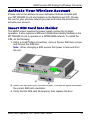
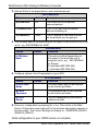
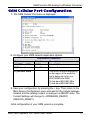
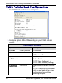
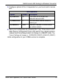
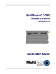
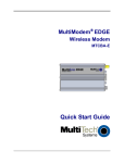
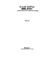
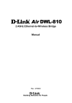
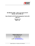
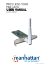
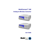
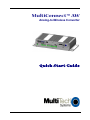
MultiConnect™ AW
Analog-to-Wireless Converter
Quick Start Guide
MultiConnect AW Analog-to-Wireless Converter
MultiConnect™ AW Quick Start
MT100A2W & MT100A2W-G
82100426L, Revision B
This publication may not be reproduced, in whole or in part, without prior
expressed written permission from Multi-Tech Systems, Inc. All rights reserved.
Copyright © 2009-10 by Multi-Tech Systems, Inc.
Multi-Tech Systems, Inc. makes no representations or warranty with respect to the
contents hereof and specifically disclaims any implied warranties of merchantability
or fitness for any particular purpose.
Furthermore, Multi-Tech Systems, Inc. reserves the right to revise this publication
and to make changes from time to time in the content hereof without obligation of
Multi-Tech Systems, Inc. to notify any person or organization of such revisions or
changes. Check Multi-Tech’s Web site for current versions of our product
documentation.
Record of Revisions
Revision
Date
A
07/15/09
B
03/26/10
Description
Initial release
Add Support portal link and firmware version 0.21G
Trademarks
Mult-Tech and the Multi-Tech logo are registered trademarks of Multi-Tech
Systems, Inc. MultiConnect is a trademark of Multi-Tech Systems, Inc. Windows is
a registered trademark of Microsoft in the U.S. and other countries.
Online Support Portal: To Create an account and submit a Support Case on the
portal, visit
https://support.multitech.com
Knowledge Base & Support Services:
Warranty
Warranty information can be found at:
www.multitech.com/support.go
http://www.multitech.com/warranty.go
World Headquarters
Multi-Tech Systems, Inc.
2205 Woodale Drive
Mounds View, Minnesota 55112
Phone: 763-785-3500 or 800-328-9717
Internet Address: www.multitech.com
Fax: 763-785-9874
Technical Support
Country
By Email
Europe, Middle East, Africa [email protected]
U.S., Canada, all others
[email protected]
2
By Phone
+(44) 118 959 7774
800-972-2439 or
763-717-5863
Multi-Tech Systems, Inc. Quick Start Guide
MultiConnect AW Analog-to-Wireless Converter
Introduction
This guide shows you how to set up your MultiConnect AW Analog-toWireless Converter. For detailed information, product description and
specifications, refer to the User Guide, available on the MultiConnect
AW CD accompanying your wireless converter.
Dial Port Caution
The dial port is not designed to be connected to a Public
Telecommunications Network (PSTN/phone line) or used outside the
building.
General Safety
The converter is designed for and intended to be used in fixed and
mobile applications. “Fixed” means that the device is physically secured
at one location and is not able to be easily moved to another location. In
a “Mobile” application, the device may be moved regularly from one
location to another.
Caution: Maintain a separation distance of at least 20 cm (8 inches)
between the transmitter’s antenna and the body of the user or nearby
persons. The modem is not designed for, nor intended to be, used in
applications within 20 cm (8 inches) of the body of the user.
RF Interference Issues
Avoid possible radio frequency (RF) interference by carefully following
the safety guidelines below.
● Switch OFF the MultiConnect when in an aircraft. The use of
cellular telephones in aircraft is illegal. It may endanger the
operation of the aircraft and/or disrupt the cellular network. Failure
to observe this instruction may lead to suspension or denial of
cellular services to the offender, legal action, or both.
● Switch OFF the MultiConnect in the vicinity of gasoline or dieselfuel pumps or before filling a vehicle with fuel.
● Switch OFF the MultiConnect in hospitals and any other place
where medical equipment may be in use.
● Respect restrictions on the use of radio equipment in fuel depots,
chemical plants, or in areas of blasting operations.
Multi-Tech Systems, Inc. Quick Start Guide
3
MultiConnect AW Analog-to-Wireless Converter
● There may be a hazard associated with the operation of your
MultiConnect in the vicinity of inadequately protected personal
medical devices such as hearing aids and pacemakers. Consult the
manufacturers of the medical device to determine if it is adequately
protected.
● Operation of the MultiConnect in the vicinity of other electronic
equipment may cause interference if the equipment is inadequately
protected. Observe any warning signs and manufacturers’
recommendations.
Vehicle Safety
● Do not use your MultiConnect while driving.
● Respect national regulations on the use of cellular telephones in
vehicles. Road safety always comes first.
● If incorrectly installed in a vehicle, the operation of Wireless
MultiConnect telephone could interfere with the correct functioning
of vehicle electronics. To avoid such problems, be sure that
qualified personnel have performed the installation. Verification of
the protection of vehicle electronics should be part of the
installation.
● The use of an alert device to operate a vehicle’s lights or horn on
public roads is not permitted.
Package Contents
●
●
●
●
●
●
1 MultiConnect Converter
1 antenna
1 RS232 cable
1 power supply
1 Quick Start Guide
1 MultiConnect CD
Note: You must supply mounting screws.
Notes:
● Your wireless provider will supply the SIM card.
● See the User Guide for antenna specifications.
4
Multi-Tech Systems, Inc. Quick Start Guide
MultiConnect AW Analog-to-Wireless Converter
Activate Your Wireless Account
Please refer to the wireless account Activation Notices included with
your MT100A2W-G unit and located on the MultiConnect CD. Choose
the one for your wireless network provider and follow the directions to
activate your account.
Insert SIM Card into Holder
The MultiConnect requires the power supply connection to begin
operation. It also requires a SIM card (Subscriber Identity Module) in the
MT100A2W-G unit to operate on a GPRS/GSM network. To install the
SIM, do the following:
1. Using a small Phillips screwdriver, remove the two SIM door screws
and remove the SIM door.
Note: When changing a SIM, ensure that power is removed from
the unit.
2. Insert the SIM card into the card holder. The above figure illustrates
the correct SIM card orientation.
3. Verify that the SIM card fits properly; then replace the door.
Multi-Tech Systems, Inc. Quick Start Guide
5
MultiConnect AW Analog-to-Wireless Converter
Connect the Antenna, Serial Cable,
Modem Cable, and Power
MT100A2W-G
MT100A2W
1. Connect a suitable antenna to the ANT connector on the
MT100A2W-G model.
2. Connect the DE9 connector (9-pin) of the RS232 cable to the
COMMAND connector on the unit and connect the other end to
serial port on your PC.
3. For the MT100A2W model, connect an RS232 cable, male
connector to the MODEM connector on the back of the unit. Connect
the other end of the cable to your external wireless modem.
4. Connect the RJ11 phone cable to the DIAL connector on the unit
and connect the other end of the phone cable to the customer’ s
analog modem.
5. Remove the protective shipping cover. Attach the appropriate input
connector to the power supply module by holding down on the slide
lock and tipping the input connector to fit into the notch on top of the
module and then lowering it into the slide lock. Then release the
slide lock.
6. Screw-on the power lead from the power supply module to the power
connection on the unit. Now, plug the power supply into your power
source.
6
Multi-Tech Systems, Inc. Quick Start Guide
MultiConnect AW Analog-to-Wireless Converter
Configure your MultiConnect
Configuration of the MultiConnect varies slightly depending on which unit
you are configuring. The MT100A2W-G has an internal GSM/GPRS
wireless modem. The MT100A2W requires a Multi-Tech CDMA, RS232
based external modem for its cellular connection. Cellular Port
configuration for the MT100A2W-G has more configuration options than
the MT100A2W unit. The differences are detailed in Device
Configuration section.
The following configuration procedures are based on the Windows XP
Operating System. Other Windows operating systems have similar paths
to HyperTerminal. See your system’s online Help if you cannot find it.
HyperTerminal
1. Go to Start I All Programs I Accessories I Communications and
then click on HyperTerminal.
2. In the Name: window, enter an applicable name for your
MultiConnect connection. Click OK.
3. Change the Connect using: window to the COM port for the
MultiConnect. Click on the down arrow and select your COM port.
4. Change the default Bits per second: window from 2400 to 115200.
Click the Apply button and then OK.
Login
A blank HyperTerminal screen is displayed. Enter the default
password of admin
What would you like this port to do? Screen is displayed.
Enter Selection => _ Enter A and press OK
Multi-Tech Systems, Inc. Quick Start Guide
7
MultiConnect AW Analog-to-Wireless Converter
Device Configuration
Initial configuration of the MultiConnect AW could involve just the
Cellular Port menu which is dependent on cellular network that you are
connecting to. The Device Configuration menu changes depending on
the cellular network. The cellular network change is in Option 1 which
defines the cellular network type; GPRS or GSM for the MT100A2W-G
unit or CDMA for the MT100A2W unit.
The GPRS cellular network is for packet switched data, GSM cellular
network is for circuit switched data, and CDMA cellular network is used
with the Multi-Tech CDMA external cellular modem.
The Analog (PSTN) Port menu is defaulted to a typical configuration.
The System Login option thru the System Reboot options refine the use
of your MultiConnect AW.
1. The Device Configuration main menu is displayed.
In the Enter option to modify => _ Enter 1 and press OK. The
Cellular Port configuration menu is displayed.
8
Multi-Tech Systems, Inc. Quick Start Guide
MultiConnect AW Analog-to-Wireless Converter
GPRS Cellular Port Configuration
1. The following options need to be configured for your GPRS
cellular network.
2. Configure options A thru D for your GPRS cellular network.
GPRS Network Dependent
Option
Default
Description
A) GPRS or GSM
B) Protocol
GPRS
TCPClient
Select GPRS
Select either TCPClient, Telnet,
UDP, or Pass Thru.
C) Inbound or
Outbound
Outbound
Select either
0)Auto Detect.
1) PPP Client (outbound), or
2) PPP Client Inbound (Listening)
D) Wireless
Connection
On Demand
Select either On Demand or
Always On.
ATTN: If Always On is desired,
wait until you have made all your
other configuration changes
before selecting this option.
Multi-Tech Systems, Inc. Quick Start Guide
9
MultiConnect AW Analog-to-Wireless Converter
3. Options E thru G are dependent on your local/remote port.
Port Dependent
Option
Default
Description
E) Local Port
23
The Local Port is for inbound
communications.
F) Remote Port
0
The TCP/IP port that the remote
device is listening on.
G) Remote IP
None
The IP address of the remote device
on the network you are going to.
4. The Wireless Band is set depending on the region of the world the unit is set
up for, e.g., 850/1900MHz for NAM.
Wireless Band
Option
Default
K) Wireless
Band
Selection
This option is default depending on
the region of the world the unit is
being set up for, e.g., 900/1800MHz
for Europe.
0) dual-band 850/1900 MHz
1) dual-band 900/1800 MHz
5. Configure options L thru N dependent on your APN.
APN Dependent
Option
Default
Selection
L) APN User
Name
The user name may not be required
by all network providers.
M) APN
Password
The password may not be required
by all network providers.
N) APN
Server
The APN assigned by your cellular
network provider.
6. Save your configuration by pressing the + key. Then return to the Main
Device Configuration menu and wait for the wireless and analog networks to
become ready. The Current Settings will change to: (WIRELESS_READY)
(ANALOG_READY).
Initial configuration of your GPRS version is complete.
10
Multi-Tech Systems, Inc. Quick Start Guide
MultiConnect AW Analog-to-Wireless Converter
GSM Cellular Port Configuration
1. The GSM Cellular Port menu is displayed.
2. Configure your GSM network dependent options.
Option
GSM network Dependent
Default
Description
A) GPRS or GSM
GPRS
Select GSM
B) Protocol
PassThru
No selection
K) Wireless Band
This option is default depending
on the region of the world the
unit is being set up for, e.g.,
850/1900MHz for NAM.
0) dual-band 850/1900 MHz
1) dual-band 900/1800 MHz
3. Save your configuration by pressing the + key. Then return to the
Main Device Configuration menu and wait for the cellular wireless
network and the analog modem to change to a READY state. The
Current Settings will change to: (WIRELESS_READY)
(ANALOG_READY).
Initial configuration of your GSM version is complete.
Multi-Tech Systems, Inc. Quick Start Guide
11
MultiConnect AW Analog-to-Wireless Converter
CDMA Cellular Port Configuration
1. The CDMA Cellular Port menu is displayed
2. Configure options A thru D depending on your CDMA cellular
network.
CDMA Network Dependent
12
Option
Default
Description
A) CDMA
CDMA (External)
No selection
B) Protocol
TCPClient
Select either TCPClient, Telnet,
UDP, or Pass Thru
C) Inbound
or Outbound
Outbound
Select either:
0) Auto Detect.
1) PPP Client (Outbound), or
2) PPP Client Inbound (Listening)
D) Wireless
Connection
OnDemand
Select either OnDemand or Always
On
ATTN: If Always On is desired, wait
until you have made all your other
configuration changes before
selecting this option.
Multi-Tech Systems, Inc. Quick Start Guide
MultiConnect AW Analog-to-Wireless Converter
3. Configure options E thru G dependent on your local and/or remote
port.
Port Dependent
Option
Default
Description
E) Local Port
23
The Local Port is the port that
listensfor inbound traffic
F) Remote Port
0
Port that remote cellular network is
listening on.
G) Remote IP
None
Remote IP address of remote device
on cellular network.
4. Save your configuration by pressing the + key. Then return to the
Main Device Configuration menu and wait for the cellular wireless
network and the analog modem to change to a READY state. The
Current Settings will change to: (WIRELESS_READY) (ANALOG_READY).
Initial configuration of your CDMA version is complete.
Multi-Tech Systems, Inc. Quick Start Guide
13
MultiConnect AW Analog-to-Wireless Converter
14
Multi-Tech Systems, Inc. Quick Start Guide
MultiConnect AW Analog-to-Wireless Converter
Multi-Tech Systems, Inc. Quick Start Guide
15
82100426L