1
2.2
Installation Procedures
2.2.1 Connecting the Power Cord
Connect the three pin waterproof power cord to the DC inlet of the In‐Vehicle Computing
Box. On the open‐wire end, one pin is reserved for positive voltage and is marked, "+";
one pin is reserved for ground and is marked, "‐"; and, one pin is reserved for the
ignition signal with an “ignition” mark.
Note!
Ignition on/off setting: The TREK‐510 supports an ignition on/off
function so that you can power on/off the TREK‐510 via the ignition
signal/voltage and connect the TREK‐510 vehicle ignition switch.
Table 2.2.1 Pin Definition of Power Cord
Pin
Definition
1
3
4
+
‐
Ignition
Color
Red
Black
Orange
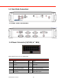
2.2.2 Power Connector
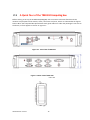
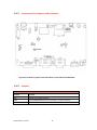
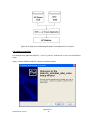
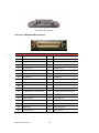
Figure 2.6. Power connector outlook
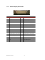
Table 2.2.2 Pin definition of PowerConnector(Molex Manufacturer part no.0430451200)
Pin
Signal
Pin
Signal
1
Chassis Ground
2
Ground
3
Ground
4
(Reserved)
5
(Reserved)
6
(Reserved)
7
Power Input (6~36 VDC)
8
Power Input (6~36 VDC)
9
Acc Ignition Input
10
Ground
11
(Reserved)
12
Power button Input
Connector : Molex 430451200
Mating connector: Molex 0430251200
TREK‐510 User manual
18