1
10.
LED LIGHTS
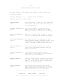
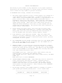
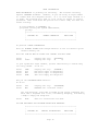
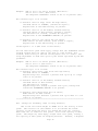
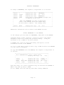
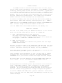
The LED lights in two vertical columns of eight located above the 8
character display indicate the following:
LEFT COLUMN:
1. REG Regrind dump solenoid operating.
2. NAT Natural dump solenoid operating.
3. COL Color drive relay operating.
4. ADD Additive drive relay operating.
5. DMP Dump valve solenoid operating.
6. ALM Alarm output operating.
7. MIX Mixer motor drive relay operating.
8. HLD Mixer flow valve is open (Optional).
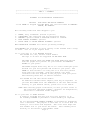
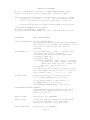
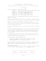
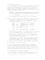
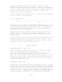
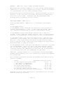
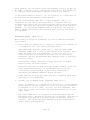
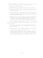
RIGHT COLUMN:
ALARMS
1.
Alarm
2.
Alarm
3.
Alarm
4.
Alarm
5.
Alarm
6. C
7. A
8. R
11.
is
is
is
is
is
on
on
on
on
on
because
because
because
because
because
Regrind ran out.
Natural ran out.
Color ran out.
Additive ran out.
Weigh bin is not within limits.
Color thumbwheel switches are locked out and the setting
being used does not match the thumbwheel setting.
Additive thumbwheel switches are locked out and the
setting being used does not match the thumbwheel setting.
Regrind thumbwheel switches are locked out and the setting
being used does not match the thumbwheel setting.
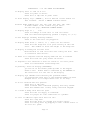
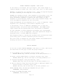
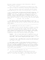
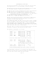
STROBE LIGHT AND BEEPER ALARMS
The Strobe light flashes and the Beeper sounds when NATURAL, COLOR, or
ADDITIVE fail to meter properly. Alarms begin after a preset number of
retries have occurred. The number of retries before Alarm is
determined by settings in the parameter table (see parameters _AL).
Regrind can also be alarmed.
12.
ALARM SILENCE
This button stops the STROBE and BEEPER ALARMS. The continuation of
the cycle to its proper completion will also stop the alarm.
If the BATCH mode is in operation, this button starts the next batch.
13.
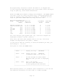
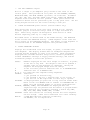
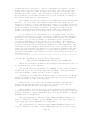
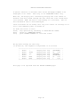
LEVEL SENSOR input
The high level sensor in the mixing chamber plugs into this outlet and
signals the controller to start a dispense cycle when it is uncovered.
The sensor must be uncovered for at least 2 seconds before a cycle will
start. (see DLY 00488) parameter). Once a dispense cycle is started,
covering the sensor does not stop it. Operation continues until the
cycle is complete.
Page 23