1
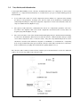
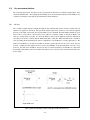
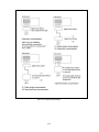
I-V method
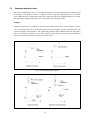
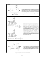
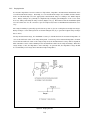
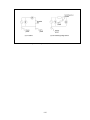
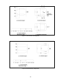
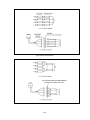
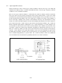
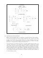
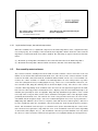
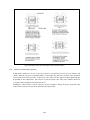
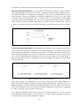
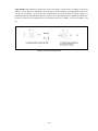
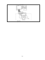
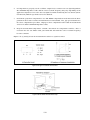
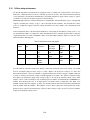
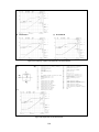
An unknown impedance Zx can be calculated from measured voltage and current values. Current is calculated using the voltage
measurement across an accurately known low value resistor, R. In
practice a low-loss transformer is used in place of R to prevent the
effects caused by placing a low value resistor in the circuit. The
transformer, however, limits the low end of the applicable frequency range.
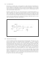
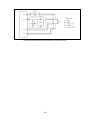
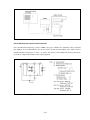
RF I-V method
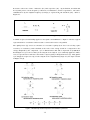
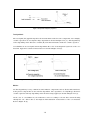
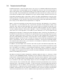
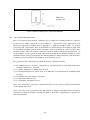
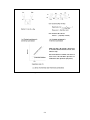
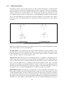
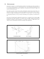
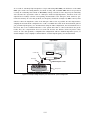
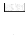
While the RF I-V measurement method is based on the same
principle as the I-V method, it is configured in a different
way by using an impedance matched measurement circuit
(50 Ω) and a precision coaxial test port for operation at higher frequencies. There are two types of the voltmeter and
current meter arrangements; which are suited to low impedance and high impedance measurements.
Impedance of the device under test (DUT) is derived from
measured voltage and current values, as illustrated. The
current that flows through the DUT is calculated from the
voltage measurement across a known low value resistor, R.
In practice, a low loss transformer is used in place of the
low value resistor, R. The transformer limits the low end of
the applicable frequency range.
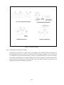
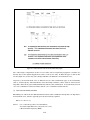
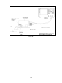
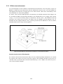
Network analysis method
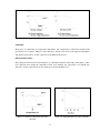
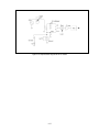
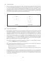
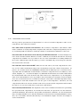
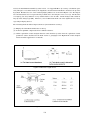
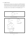
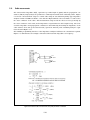
The reflection coefficient is obtained by measuring the ratio
of an incident signal to the reflected signal. A directional
coupler or bridge is used to detect the reflected signal and a
network analyzer is used to supply and measure the signals.
Since this method measures reflection at the DUT, it is
usable in the higher frequency range.
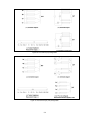
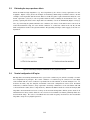
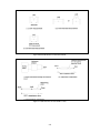
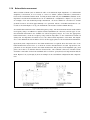
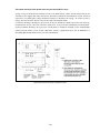
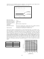
Figure 2-1. Impedance measurement method (2 of 3)
2-2