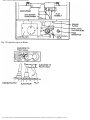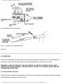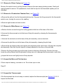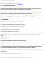
1
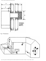
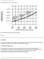
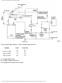
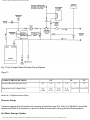
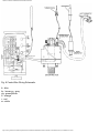
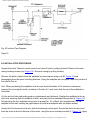
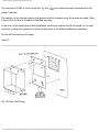
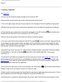
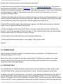
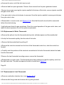
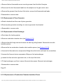
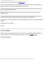
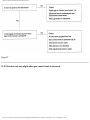
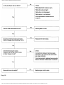
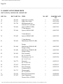
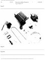
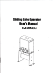
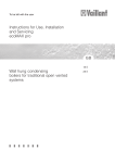
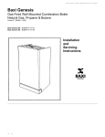
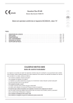
INSTALLATION & SERVICING INSTRUCTIONS
INSTALLATION & SERVICING INSTRUCTIONS
WM15/30 BFa, WM30/40 BF, WM40/50 BF
From Serial No.
Wall Mounted Domestic Gas Fired Boiler, Natural Draught Balanced Flue
LEAVE THESE INSTRUCTIONS ADJACENT TO THE GAS METER.
Page 0
Page 0a
MYSON ECONOMIST WM15/30 BFa, WM30/40 BF, WM40/50 BF INSTALLATION AND
SERVICING INDEX
SECTION
1.0
2.0
3.0
4.0
SUBJECT
TECHNICAL DATA
SAFETY
RANGE RATING
BOILER LOCATION
http://www.partsarena.com/baxi/System/DATA/Dx/DS1/installation/2102/I01-2102/I01-2102.htm (1 of 44)14/10/2004 17:30:48
PAGE
3
7
8
8
INSTALLATION & SERVICING INSTRUCTIONS
5.0
6.0
7.0
8.0
9.0
10.0
11.0
WATER SYSTEM
INSTALLATION PROCEDURE
INITIAL LIGHTING
COMMISSIONING
SERVICING
FAULT FINDING
SHORT LIST OF SPARE PARTS
10
16
18
19
21
27
31
Page 1
IT IS THE LAW THAT THIS APPLIANCE BE INSTALLED BY BRITISH GAS OR ANOTHER CORGI
REGISTERED INSTALLER.
INTRODUCTION
This Installation Manual is applicable to the following models from the Potterton Myson Economist
range of gas boilers:
WM15/30 BFa
G.C. No. 41.838.90
WM30/40 BF
G.C. No. 41.838.82
WM40/50 BF
G.C. No. 41.838.85
These are balanced flue, wall mounted, central heating boilers, for use on natural gas only.
They require pumped circulation and cannot be used on gravity circulations. A bypass must always be
fitted into the heating system, across the boiler. A pump overrun thermostat is fitted as standard and a
permanent live connection to the boiler is required.
They may be range rated to suit individual heating systems.
Myson Ltd, pursues a policy of continuing improvement in design and performance of its products. The
right is therefore reserved to vary specification without notice.
Page 2
http://www.partsarena.com/baxi/System/DATA/Dx/DS1/installation/2102/I01-2102/I01-2102.htm (2 of 44)14/10/2004 17:30:48
INSTALLATION & SERVICING INSTRUCTIONS
1.0 TECHNICAL DATA RATINGS
WM15/30 BFa
MAXIMUM
MID RANGE
MINIMUM
8.8
6.6
4.4
30,000
22,500
15,000
11.0
8.4
5.6
37,500
28,500
19,200
BURNER PRESSURE mbar
11.8
6.8
3.3
in wg
4.7
2.7
1.3
GAS RATE m3/h
1.0
0.8
0.5
ft3/h
36.0
28.0
19.0
MAXIMUM
MID RANGE
MINIMUM
11.7
10.3
8.8
40,000
35,000
30,000
14.7
13.0
11.3
50,000
44,300
38,500
BURNER PRESSURE mbar
14.6
11.7
8.8
in wg
5.9
4.7
3.5
GAS RATE m3/h
1.4
1.2
1.0
ft3/h
48.0
43.0
37.0
MAXIMUM
MID RANGE
MINIMUM
14.7
13.2
11.7
50,000
45,000
40,000
18.3
16.7
15.0
62,500
57,000
51,300
BURNER PRESSURE mbar
14.9
12.5
10.2
in wg
6.0
5.0
4.1
GAS RATE m3/h
1.7
1.6
1.4
ft3/h
60.0
55.0
50.0
SIZE mm
SIZE In
MARKING
WM15/30 BFa
2.70
0.106
270
WM30/40 BF
3.00
0.118
300
HEAT OUTPUT kW
Btu/h
HEAT INPUT kW
Btu/h
WM30/40 BF
HEAT OUTPUT kW
Btu/h
HEAT INPUT kW
Btu/h
WM40/50 BF
HEAT OUTPUT kW
Btu/h
HEAT INPUT kW
Btu/h
INJECTORS
MODEL
http://www.partsarena.com/baxi/System/DATA/Dx/DS1/installation/2102/I01-2102/I01-2102.htm (3 of 44)14/10/2004 17:30:48
INSTALLATION & SERVICING INSTRUCTIONS
WM40/50 BF
3.30
0.130
330
OVERALL DIMENSIONS
HEIGHT
WIDTH
DEPTH
MODEL
mm
In
mm
In
mm
In
WM 15/30 BFa
600
23 5/8
327
12 7/8
300
11 3/4
WM30/40 BF
650
25 5/8
361
14 1/4
300
11 3/4
WM40/50 BF
650
25 5/8
407
16
300
11 3/4
Page 3
WEIGHTS
MODEL
TOTAL
WEIGHT
LIFT
WEIGHT
kg
Ib
kg
Ib
WM15/30 BFa
25
56
16
35
WM30/40 BF
31
68
21
46
WM40/50 BF
35
78
23
50
WATER CAPACITIES
MODEL
litre
pint
WM15/30 BFa
0.7
1.3
WM30/40 BF
1.1
1.9
WM40/50 BF
1.3
2.2
MINIMUM WATER FLOW RATES (ie to give 11 °C temperature rise)
MODEL
litre/h
gal/h
WM15/30 BFa
690
150
WM30/40 BF
920
200
WM40/50 BF
1150
250
http://www.partsarena.com/baxi/System/DATA/Dx/DS1/installation/2102/I01-2102/I01-2102.htm (4 of 44)14/10/2004 17:30:48
INSTALLATION & SERVICING INSTRUCTIONS
BYPASS DIAMETER 15mm diameter.
GAS CONNECTION Rc 1/2 (1/2 in BSP int)
WATER CONNECTION Flow 22mm compression fitting LH side.
Return 22mm compression fitting RH side.
ELECTRICITY SUPPLY 240V-50Hz, fused at 3A.
MINIMUM STATIC HEAD 0.2m (8in)
MAXIMUM STATIC HEAD 30.5m (100ft)
Page 4
MAXIMUM BOILER THERMOSTAT SETTING 79°C (174°F)
STANDARD FLUE Wall thickness from 230mm (9in) to 355mm (14in)
MINIMUM CLEARANCES FOR INSTALLATION AND SERVICING
Left and right side
6mm (1/4in)
Top of boiler
75mm (3in)
Underside of boiler
125mm (5in)
Front of boiler
610mm (24in)
FREE AREA OF CUPBOARD VENTS
MODEL
AIR FROM ROOM
in
2
2
cm
AIR FROM OUTSIDE
cm
in
2
2
WM15/30 BFa
99
15
49
8
WM30/40 BF
132
20
66
10
WM40/50 BF
165
26
82
13
http://www.partsarena.com/baxi/System/DATA/Dx/DS1/installation/2102/I01-2102/I01-2102.htm (5 of 44)14/10/2004 17:30:48
INSTALLATION & SERVICING INSTRUCTIONS
DIMENSION FOR INSTALLATION, mm (See Fig. 1)
MODEL
A
B
C
D
E
F
G
H
J
K
L
M
N
P
WM15/30 BFa
327 600 300 252 45 255 500 100 128 287 282 568 323
225
WM30/40 BF
361 650 300 286 45 255 550 100 128 287 316 618 373
259
WM40/50 BF
407 650 300 332 45 255 550 100 128 332 362 618 328
305
TERMINAL GUARDS REFERENCE TYPE
MODEL
TOWER FLUE
QUINNELL BARRETT
WM15/30 BFa
A
E
WM30/40 BF
A
E
WM40/50 BF
D
M3
Page 5
http://www.partsarena.com/baxi/System/DATA/Dx/DS1/installation/2102/I01-2102/I01-2102.htm (6 of 44)14/10/2004 17:30:48
INSTALLATION & SERVICING INSTRUCTIONS
Fig. 1 Dimensions
http://www.partsarena.com/baxi/System/DATA/Dx/DS1/installation/2102/I01-2102/I01-2102.htm (7 of 44)14/10/2004 17:30:48
INSTALLATION & SERVICING INSTRUCTIONS
Fig. 2 Balanced Flue Terminal Positions
Fig. 3 Resistance to Water Flow through Boiler
Page 6
2.0 SAFETY
It is essential that the boiler is installed in accordance with this manual. It is the law that the installation
be carried out by British Gas or another CORGI Registered Installer.
2.1 Statutory Requirements
The installation of the boiler must be in accordance with the current issue of the Gas Safety
(Installation and Use) Regulations, Building Regulations, Building Standards (Scotland) Regulations,
current IEE wiring regulations and model and local water undertaking bylaws. Detailed
recommendations are contained in the following British Standards.
http://www.partsarena.com/baxi/System/DATA/Dx/DS1/installation/2102/I01-2102/I01-2102.htm (8 of 44)14/10/2004 17:30:48
INSTALLATION & SERVICING INSTRUCTIONS
BS5440 Part 1,
1990 ;
BS5440 Part 2,
1989;
BS5449
1990;
BS5546
1990;
BS6798
1987;
BS6891
1988;
2.2 Gas Supply
Installation pipes should be fitted, tested for soundness and purged in accordance with BS6891, 1988.
Pipework from the meter to the boiler should be of a size to ensure an adequate supply of gas, as set
down in BS6891, 1988. Normally 15mm diameter pipe will be necessary to supply the gas rate shown
in the Technical Data section, being adequate for Model WM1 5/30 BFa up to a length of 15m, for
Model WM30/40 BF up to a length of of 9m and for Model WM40/50 BF up to a length of 7.5m. These
lengths are reduced by 0.5m for each elbow and tee.
2.3 Electricity Supply
All electrical wiring must be carried out by a qualified electrician. All external components should be of
an approved type and wired in accordance with current IEE regulations and any local regulations that
may apply.
The appliance must be earthed. The supply to the boiler should be 240V - 50Hz and fused at 3A. The
rating of the boiler is approximately 5VA.
IT MUST BE POSSIBLE TO COMPLETELY ISOLATE THE BOILER AND ALL ASSOCIATED
CONTROLS FROM MAINS ELECTRICITY. THE COMPLETE ELECTRICAL SYSTEM MUST BE
POWERED FROM A SINGLE POINT, WHICH SERVES THE HEATING SYSTEM ONLY. THIS
POINT CAN BE CONNECTED USING A FUSED THREE PIN PLUG AND SHUTTERED SOCKET,
BOTH COMPLYING WITH THE REQUIREMENTS OF BS1363. ALTERNATIVELY, A FUSED
DOUBLE POLE SWITCH WITH A CONTACT SEPARATION OF AT LEAST 3mm ON BOTH POLES
MAY BE USED.
All external cables to the boiler should be rated to take at least 3A, ie at least 0.75mm2 (24/0.2mm) to
BS6500 1990, Table 16. There must be a permanent live connection to the boiler, unswitched by any
external controls, for the pump overrun facility to work.
Page 7
3.0 RANGE RATING
The boilers covered by this manual can be range rated to suit individual systems. They can be used
where the maximum loads fall within the values of heat output shown in the Technical Data Section.
http://www.partsarena.com/baxi/System/DATA/Dx/DS1/installation/2102/I01-2102/I01-2102.htm (9 of 44)14/10/2004 17:30:48
INSTALLATION & SERVICING INSTRUCTIONS
NOTE: The boilers are factory set to give the maximum heat output.
4.0 BOILER LOCATION
The appliances are not suitable for external installation.
The boiler may be installed in any room, although particular attention is drawn to the requirements of
current IEE regulations and, in Scotland, the electrical provisions of the Building Standards applicable
in Scotland, with respect to the installation of a boiler in a room containing a bath or shower. Where a
room sealed boiler is installed in a room containing a bath or shower, any electrical switch or boiler
control utilising mains electricity should be so situated that it cannot be touched by a person using the
bath or shower.
The boiler is suitable for installation onto a combustible wall. If the boiler is to be fitted in a timber
framed building, it should be fitted in accordance with the British Gas Publication "Guide for Gas
Installations in Timber Framed Houses," reference DM2. If in doubt, advice may be sought from the
local Gas Region.
4.1 Installation in Cupboard or Compartment
A cupboard or compartment used to enclose the boiler should be designed and constructed
specifically for this purpose. An existing cupboard or compartment may be used provided that it is
modified for this purpose. Details of cupboard or compartment design are given in BS6798 1987.
These are room sealed appliances and therefore no air supply is required for combustion. However, if
the boiler is installed in a cupboard or compartment, permanent ventilation is required at high and low
level for cooling purposes, either direct from outside or from a room. Both high and low level air vents
should communicate with the same wall to outside air, or to the same room. Each vent should have a
free area of at least that given in the Technical Data Section. Further details are given in BS5440 Part
2, 1989.
4.2 Boiler Clearances
The boiler position should be such that the following minimum clearances are provided for installation
and servicing:
Left and right hand side
6mm (1/4in)
Top of wallplate
75mm (3in)
Underside of wallplate
125mm (5in)
Front of wallplate
910mm (36in)
http://www.partsarena.com/baxi/System/DATA/Dx/DS1/installation/2102/I01-2102/I01-2102.htm (10 of 44)14/10/2004 17:30:48
INSTALLATION & SERVICING INSTRUCTIONS
Page 8
4.3 Positioning of Balanced Flue Terminal
The boiler is supplied with a standard flue suitable for wall thicknesses from 230mm (9in) to 355mm
(14in). The boiler terminal must be installed such that it is exposed to external air which has a free
passage across it at all times, so that combustion products can disperse freely.
In certain weather conditions the terminal may steam, and positions where this could cause a nuisance
should be avoided.
If the terminal discharges onto a passageway or pathway or over an adjoining property, check that the
combustion products will not cause a nuisance and that the terminals will not obstruct the
passageway. In some areas, local bylaws ask for a minimum height for projections from a wall above a
public footpath.
If the terminal is fitted within 850mm of a plastic gutter, or within 450mm of painted eaves or painted
gutter, an aluminium shield at least 750mm long should be fitted to the underside of the gutter or
painted surface.
If a terminal is fitted less than 2m above a balcony, above ground or above a flat roof to which people
have access, then a suitable terminal guard must be provided. These are available from Tower Flue
Components Ltd, Vale Rise, Tonbridge, Kent, or from Quinnell Barrett Ltd, 884 Old Kent Road, London
SE15, quoting reference type shown in Technical Data Section. The terminal guard should be screwed
to the wall so that it is at least 50mm from all parts of the terminal.
The minimum acceptable spacings from the terminal to any obstructions and ventilation openings are:
(refer to Figure 2)
TERMINAL POSITION
A
B
C
D
E
F
G
H
I
Directly below an openable window or any other opening, ie
air brick
Below gutters, soil pipes or drain pipes
Below eaves
Below balconies or car port roof
From vertical drain pipes and soil pipes
From internal or external corners
Above ground, roof or balcony level
From a surface facing a terminal
From a terminal facing a terminal
http://www.partsarena.com/baxi/System/DATA/Dx/DS1/installation/2102/I01-2102/I01-2102.htm (11 of 44)14/10/2004 17:30:48
MINIMUM
SPACING
300mm
300mm
300mm
600mm
75mm
600mm
300mm
600mm
600mm
INSTALLATION & SERVICING INSTRUCTIONS
J
K
L
From opening in a car port eg door, window into dwelling
Vertically from a terminal on the same wall
Horizontally from a terminal on the same wall
1200mm
1500mm
300mm
Additional notes for car ports and other single storey "add-on" extensions:
Any car port or other add-on extension should consist of a roof, or a roof and one other wall. If it
consists of a roof and two other walls the installation shall be treated as suspect and further advice
sought.
If there is any opening in the car port into the dwelling, eg door, window, then the terminal must be at
least 1200mm away from the opening. If it is less, then the installation must be treated as suspect and
further advice sought. If it is more than 1200mm, the D, F,H, and I shall apply where D is the vertical
distance between the lowest point of the roof and the top of the terminal.
If the roof is plastic, then the installation should be treated with great care, as there is no simple way of
protecting the roof.
Page 99
5.0 WATER SYSTEM
The boiler is supplied with copper compression water fittings, of the size shown in the Technical Data
Section. The flow and return pipes are identified by labels and on Figure 13.
The installation should comply with the appropriate requirements of BS5449, 1990, BS5546, 1990 and
BS6798, 1987. The boiler is designed for use on fully pumped systems only, of the open vented or
sealed type.
5.1 Open Vented or Sealed System
Pump
The pump should be capable of providing the mimimum water flow rate, as shown in the Techmical
Data Section. The boiler pressure loss graph (Figure 3) should be considered when selecting the
pump. The recommended selection is a Myson Unit 5 or equivalent. The pump should be fitted with
isolation valves and in a readily accessible position in the flow pipe from the boiler.
Drain Cock
At least one drain cock should be fitted, at the lowest point in the system.
http://www.partsarena.com/baxi/System/DATA/Dx/DS1/installation/2102/I01-2102/I01-2102.htm (12 of 44)14/10/2004 17:30:48
INSTALLATION & SERVICING INSTRUCTIONS
Bypass
The flow through the boiler must not be allowed to fall below the figure shown in the Technical Data
Section. Therefore a bypass of at least the diameter shown in the Technical Data Section, should be
fitted across the boiler. The total length of the bypass loop should be at least 3m. It is acceptable to
use a radiator that cannot be shut off or adjusted by the customer as the bypass.
The use of this bypass will mean the temperature differential across the boiler will be less than that
across the heating system.
External Controls
It should not be possible for the boiler to fire when external controls have shut all waterways or
switched off the pump.
Inhibitor
When an inhibitor is to be used in the system, contact should be made with the inhibitor manufacturer,
so they can recommend their most suitable product. The boiler has a copper heat exchanger.
Working Pressure
The maximum working pressure to which the boiler should be subjected is 3 bar (44 Ibf/in2). The
normal recommended range of pressure is from 0.1 bar (1.5 lbf/in2) to 1.5 bar (22 lbf/in2).
Page 10
5.2 Open Vented System Only
Schematic layouts are shown in Figures 4 to 6 .
Hot Water Storage Cylinder
The cylinder must be either an indirect type or a direct type fitted with an immersion calorifier that is
suitable for the system pressure. The cylinder should be to the requirements of BS1566, Part 1, 1984.
Single feed (self priming) indirect cylinders are not recommended.
Open Vent and Cold Feed
A combined feed and vent is recommended, as there is no possibility of either pumping over or air
being drawn in. A system using a Myson Aerjec is equivalent to a combined feed and vent, with
improved air removal from system. The combined feed and vent must be at least 22mm diameter.
http://www.partsarena.com/baxi/System/DATA/Dx/DS1/installation/2102/I01-2102/I01-2102.htm (13 of 44)14/10/2004 17:30:48
INSTALLATION & SERVICING INSTRUCTIONS
Some Water Authorities require a stop cock in the cold feed pipe, in which case, a combined feed and
vent cannot be used. A close coupled feed and vent should then be used, taking note of the vent
lengths required to prevent pump surges causing either pumping over or air to be drawn in. The vent
must be at least 22mm diameter and the feed at least 15mm diameter. There must be no valves or
restrictions between the boiler and the outlet of the vent with any system. The feed and expansion
cistern should be not less than 23 litre (5 gallon) capacity, and should not be situated more than 30
metres (100ft) above the boiler.
5.3 Sealed Systems Only
A schematic layout is shown in Figure 7 .
Safety Valve
A spring loaded safety valve complying with the relevant requirements of BS6759, Part 1, 1984, should
be fitted, and should be preset to operate at 3 bar (44 lbf/in2). It should be positioned in the flow pipe
close to the boiler with no valves or restrictions between the safety valve and the boiler. The safety
valve should be positioned, or any discharge pipe so arranged, that discharge of water or steam
cannot create a hazard to occupants, or damage electrical components or wiring.
Expansion Vessel
A diaphragm type expansion vessel, complying with the requirements of BS4814, 1990, should be
connected at a point close to the inlet side of the pump, in the flow pipe from the boiler. The vessel
should be chosen to suit the volume of water in the system and the charge pressure, which should not
be less than the static head at the point of connection. Further details can be obtained from
"Specification for Domestic Hot Wet Central Heating," published by British Gas.
Page 11
http://www.partsarena.com/baxi/System/DATA/Dx/DS1/installation/2102/I01-2102/I01-2102.htm (14 of 44)14/10/2004 17:30:48
INSTALLATION & SERVICING INSTRUCTIONS
Fig. 4 Fully Pumped Open System - Combined Feed and Vent. (Some water authorities require a stop
cock in the cold-feed pipe, in which case this system cannot be used).
http://www.partsarena.com/baxi/System/DATA/Dx/DS1/installation/2102/I01-2102/I01-2102.htm (15 of 44)14/10/2004 17:30:48
INSTALLATION & SERVICING INSTRUCTIONS
Fig. 5 Fully Pumped Open System - Myson Aerjec.
(Improves air removal from system).
Page 12
http://www.partsarena.com/baxi/System/DATA/Dx/DS1/installation/2102/I01-2102/I01-2102.htm (16 of 44)14/10/2004 17:30:48
INSTALLATION & SERVICING INSTRUCTIONS
Fig. 6
Fully Pumped Open System - Close Coupled Feed and Vent
MODEL
WM 15/30 BFa
WM 30/40 BF
WM 40/50 BF
VENT
A
230
330
420
LENGTH
B
260
290
330
A - Length Of Dry Vent
B - Length of Water Filled Vent
Vent lengths do not need to be vertical
http://www.partsarena.com/baxi/System/DATA/Dx/DS1/installation/2102/I01-2102/I01-2102.htm (17 of 44)14/10/2004 17:30:48
INSTALLATION & SERVICING INSTRUCTIONS
Fig. 7 Fully Pumped Sealed System Piping Diagram.
Page 13
CHARGE PRESSURE (BAR)
0.5
1.0
Pre-pressurisation pressure (bar)
0.5
1.0
1.5
1.0
Expansion vessel volume (litre)
Ax
0.066
Ax
0.112
Ax
0.207
Ax
0.087
1.5
1.5
1.5
A x 0.152 A x 0.125
where A = System volume (litre)
Pressure Gauge
A pressure gauge with set pointer and covering at least the range 0 to 4 bar (0 to 58 lbf/in2) should be
permanently fitted to the system, so as to be visible to the person carrying out the filling operation.
Hot Water Storage Cylinder
http://www.partsarena.com/baxi/System/DATA/Dx/DS1/installation/2102/I01-2102/I01-2102.htm (18 of 44)14/10/2004 17:30:48
INSTALLATION & SERVICING INSTRUCTIONS
The cylinder should be either an indirect type or a direct type fitted with an immersion calorifier that is
suitable for the system pressure.
The cylinder should be to the requirements of BS1566, Part 1, 1984. Single feed (self priming) indirect
cylinders must not be used on a sealed system.
Filling and Make-up
There must be no permanent or temporary connection to the mains water supply, or to a water storage
cistern supplying domestic water, even through a non-return valve layout, without the approval of the
local Water Authority. If the system is to be filled from the mains via a temporary hose, the filling point
will require a non-return valve and
anti-vacuum valve on the mains side of the fill point stop valve, both valves UK Water Fittings Byelaws
Scheme Listed.
Provision should be made for replacing water lost from the system, from a make-up vessel mounted in
position higher than the top point of the system and connected through a non-return valve to the return
side of either the hot water cylinder or heating circuit. Alternatively, where access to a make-up vessel
would be difficult, provision for make-up can be made by pre-pressurisation of the system.
Page 14
http://www.partsarena.com/baxi/System/DATA/Dx/DS1/installation/2102/I01-2102/I01-2102.htm (19 of 44)14/10/2004 17:30:48
INSTALLATION & SERVICING INSTRUCTIONS
Fig. 8 Control Box Wiring Schematic.
b - blue
br - brown gy - grey
g/y- green/yellow
o - orange
r - red
w - white
http://www.partsarena.com/baxi/System/DATA/Dx/DS1/installation/2102/I01-2102/I01-2102.htm (20 of 44)14/10/2004 17:30:48
INSTALLATION & SERVICING INSTRUCTIONS
Fig. 9 Function Flow Diagram.
Page 15
6.0 INSTALLATION PROCEDURE
Unpack the boiler. Remove control cover from base of boiler by sliding forward. Remove the main
casing locating screws (see Figure 13). Remove casing by pulling forward.
Remove the boiler chassis from the wallplate by removing two wing nuts (B, Figure 10) and
disengaging from the lower mounting brackets. Using the wallplate as a template, mark the position of
the hole for the air
duct. When positioning the wallplate, due account should be taken of the minimum clearances
required for servicing the boiler, as shown in Section 4.2, and check that the top of the wallplate is
horizontal.
Cut the air duct hole and make good any plasterwork and brickwork. Realign the wallplate to the air
duct hole, ensuring that the wallplate is level, and mark the four wallplate fixing holes (A, Figure 10).
Drill and plug the four wallplate fixing holes to accept No. 10 x 50mm (2in) woodscrews. Fix the
wallplate to the wall, sealing the gap between the wall and wallplate with a suitable sealant.
Unpack the flue terminal and ducts, slide the telescopic ducts apart. Secure the inner flue duct and
then the inner air duct to the back of the boiler, using the seven screws provided (C, Figure 11). Apply
http://www.partsarena.com/baxi/System/DATA/Dx/DS1/installation/2102/I01-2102/I01-2102.htm (21 of 44)14/10/2004 17:30:48
INSTALLATION & SERVICING INSTRUCTIONS
a layer of sealant to seal between the boiler and the wallplate. Lift the boiler and pass the ductwork
through the hole in the wall. Engage the bottom of the boiler on the lower mounting brackets and
secure the top of the boiler with the two wing nuts (B, Figure 10).
From outside the building, insert the outer flue duct/flue terminal into the wall opening, and slide it into
the inner flue duct. Mark the positions of the two flue terminal fixing holes (D, Figure 11). Remove the
outer flue duct/flue terminal and make good the external wall surface. Drill and plug the flue terminal
fixing holes to accept No. 10 x 25mm (1 in) screws. Apply a layer of sealant, suitable for external use,
around the edge of the wall opening. Insert the outer air duct into the wall opening, with the welded
seam at the top, and slide it over the inner air duct until the flange seals on the layer of sealant. Seal
the join between the two air ducts on the inside with the tape provided.
Locate the outer flue duct/flue terminal into the inner flue duct and slide into position. Fix the flue
terminal to the wall with the screws provided.
Connect the gas supply to the boiler, see Section 2.2.
Connect the water system, see Section 5 . Remove the water circulating pump, flush out the system
with cold water and replace the pump. Fill the system with water, clear any air locks and check for
water soundness, for sealed systems at a pressure of 2.5 bar (36 Ibf/in2)
For sealed systems, pressurise the system to check the operation of the safety valve. This should be
within 0.3 bar (4 lbf/in2) of the preset pressure of 3 bar (44 Ibf/in2). De-pressurise to the desired
operating pressure.
Connect the electricity supply, see Section 2.3. Remove the control box cover by undoing the two
screws at the front of the box, the cover can then be slid forward and disengaged. Care should be
taken not to damage the thermostat capillary which passes through a grommet in the cover, and not to
allow the cover to hang on the electrical cables.
A terminal block is provided for the supply connections to the boiler, connections for external controls if
required, and connections for the pump, refer to Figures 8 and 9.
The supply connection to the terminal block (L) must be permanent live, unswitched by any external
controls. The supply cable should pass through the grommet provided, and should be clamped using
the cable clamp provided. The length of the earth wire must be such that if the supply cable slips out of
the cable clamp, the live and neutral wires become taut before the earth wire.
If external controls are not to be fitted, leave the factory fitted link from L2 to SL in position. Otherwise
remove the link.
The connection L2 is a permanent live, internally linked to L, and is provided to feed external controls if
required. SL is the switched live from the external controls, N and
2
2
are neutral and earth
connections for external controls as required.
http://www.partsarena.com/baxi/System/DATA/Dx/DS1/installation/2102/I01-2102/I01-2102.htm (22 of 44)14/10/2004 17:30:48
INSTALLATION & SERVICING INSTRUCTIONS
The connection PUMP is for the pump live, N and
3
3
are neutral and earth connections for the
pump if required.
The cable(s) to the external controls and pump should be clamped using the bushes provided. Allow
150mm (6in) of slack in all cables to facilitate servicing.
In the event of an electrical fault after installation, preliminary checks should be carried out, ie earth
continuity, polarity and resistance to earth, as described in the Minitest Multimeter handbook..
Do not refit the casing at this stage.
Page 16
Fig. 10 Boiler Wall Fixing
http://www.partsarena.com/baxi/System/DATA/Dx/DS1/installation/2102/I01-2102/I01-2102.htm (23 of 44)14/10/2004 17:30:48
INSTALLATION & SERVICING INSTRUCTIONS
Fig. 11 Flue Duct /Terminal Assembly.
.
Fig. 12 View of Gas Controls
http://www.partsarena.com/baxi/System/DATA/Dx/DS1/installation/2102/I01-2102/I01-2102.htm (24 of 44)14/10/2004 17:30:48
INSTALLATION & SERVICING INSTRUCTIONS
Page 17
7.0 INITIAL LIGHTING
See Figure 12
a Check that the electricity supply and gas service cock are OFF.
b Remove the screw from the gas control valve inlet pressure test point.
c Turn on the gas supply and open the gas service cock to purge air from the appliance supply pipe.
d Replace the gas control valve inlet pressure test point screw and allow the purged gas to disperse.
e Check that the gas control knob is turned fully clockwise to the OFF position
thermostat knob is turned fully anti-clockwise to the OFF position.
and that the boiler
f Remove the burner pressure test screw and connect a pressure gauge.
g Turn qas control knob anti-clockwise to the PILOT position
, push in and hold it depressed.Push
in and release the piezo igniter button repeatedly until the pilot flame can be seen through the sight
window. When the pilot has lit, continue to press in the gas control knob for a further fifteen seconds,
then release. The pilot should stay alight.
h SHOULD THE PILOT GO OUT AT THIS OR ANY OTHER STAGE, TURN GAS CONTROL KNOB
CLOCKWISE TO THE OFF POSITION
instruction "g."
AND WAIT FOR THREE MINUTES. Then repeat
i Check that the pilot flame envelopes the thermocouple tip by 6-8mm (see Figure 14). Refer to the
fault finding section if the pilot flame is not satisfactory. Remove the combustion chamber door (see
Section 9.1.2) and check for gas soundness at the pilot tube nut on the pilot assembly. Replace the
door, ensuring all screws are fully tightened.
j Push in and turn gas control knob anti-clockwise to the ON position(
Setting 5, and ensure all external controls are calling for heat.
). Set the boiler thermostat to
k Switch on the electricity supply and check that the main burner lights smoothly from the pilot. Test for
gas soundness around all boiler gas components using leak detection fluid.
l Allow the boiler to operate for approximately 10 minutes, then check the burner gas pressure. Note
http://www.partsarena.com/baxi/System/DATA/Dx/DS1/installation/2102/I01-2102/I01-2102.htm (25 of 44)14/10/2004 17:30:48
INSTALLATION & SERVICING INSTRUCTIONS
that the boiler is factory preset to give its maximum heat output.
m Adjust the burner gas pressure to the figures shown in the Technical Data Section. The pressure
adjustment screw location is shown on Figure 12 . After removal of the plastic plug, turn the screw anticlockwise to increase the pressure, and clockwise to decrease the pressure. Check that the flames are
not yellow tipping or lifting off. If the appliance gas rate is in doubt, check by timing one or more
revolutions of the gas meter.
n Replace the plastic plug for the pressure adjustment screw, to prevent unauthorised adjustment, and
mark the appliance data badge (situated on lower right hand side of wallplate) with the arrow provided,
to show the burner pressure and heat output, that the appliance has been set to.
o Switch OFF electricity supply, disconnect pressure gauge, and replace burner pressure t est point
screw. Check for gas soundness at the test point.
p Check the operation of the flame failure device in the gas control valve as follows. With the main
burner lit, turn off the gas supply at the service cock. A "click" indicating that the device has operated
should be heard within 60 seconds of turning off the gas.
q Check that the boiler and all external controls operate satisfactorily.
r Check that the thermocouple output is in the range 6-10mV closed circuit.
Page 18
8.0 COMMISSIONING
Light the boiler and heat the system to the maximum working temperature. The maximum boiler
thermostat setting is 79°C (174°F).
Examine for leaks, turn boiler off, and drain system while hot. Refill and vent system. For sealed
systems, adjust the cold fill pressure to the required setting, and then disconnect any temporary
connection to the mains water supply.
8.1 SYSTEM BYPASS
It is important that the water flow rate through the boiler does not fall below the figure shown in the
Technical Data Section, at any time when the boiler is firing. Therefore a bypass must be fitted.
To adjust the bypass, fire the boiler with a full load, ie central heating and domestic hot water both on,
and the bypass fully closed. Adjust the pump to give a temperature rise of 11 °C (20°F) across the
system. The system should then be switched to minimum load, ie central heating only with the radiator
valves turned off. If noise is experienced under these conditions, the bypass valve should be gradually
http://www.partsarena.com/baxi/System/DATA/Dx/DS1/installation/2102/I01-2102/I01-2102.htm (26 of 44)14/10/2004 17:30:48
INSTALLATION & SERVICING INSTRUCTIONS
opened to increase the flow rate through the boiler until the noise stops.
NOTE: When the boiler is first fired, a smell may occur. This will clear within a few hours of operation.
NOTE: A limit thermostat is fitted to the boiler, wired to interrupt the thermocouple circuit, and so
causing safety shut down in the event of an overheat condition. This limit thermostat is of a selfresetting type. Should the thermostat trip during commissioning, allow the system to cool, then relight
the boiler.
Refit the casing and control cover. Hand all instructions to the user or purchaser for retention.
Demonstrate and explain the safe and efficient operation of the boiler. Advise the user or purchaser
that for continued efficient and safe operation of the boiler, it is important that servicing is carried out
annually.
Page 19
http://www.partsarena.com/baxi/System/DATA/Dx/DS1/installation/2102/I01-2102/I01-2102.htm (27 of 44)14/10/2004 17:30:48
INSTALLATION & SERVICING INSTRUCTIONS
Fig. 13 Internal Layout of Boiler.
http://www.partsarena.com/baxi/System/DATA/Dx/DS1/installation/2102/I01-2102/I01-2102.htm (28 of 44)14/10/2004 17:30:48
INSTALLATION & SERVICING INSTRUCTIONS
Fig. 14 Details of Pilot Assembly.
Fig. 1 5 Location of Thermostat Phial.
Page 20
9.0 SERVICING
This section describes the annual servicing procedure, and gives instructions for the replacement of
faulty parts. Servicing must be carried out by a competent person at least once a year.
WARNING: ALWAYS TURN OFF THE GAS SUPPLY AT THE INLET SERVICE COCK, AND
SWITCH OFF AND DISCONNECT THE ELECTRICITY SUPPLY TO THE APPLIANCE, BEFORE
COMMENCING SERVICING.
9.1 Annual Routine Service
This is normally confined to cleaning the main burner, main injector, pilot injector and heat exchanger,
and checking the operation of boiler control.
http://www.partsarena.com/baxi/System/DATA/Dx/DS1/installation/2102/I01-2102/I01-2102.htm (29 of 44)14/10/2004 17:30:48
INSTALLATION & SERVICING INSTRUCTIONS
9.1.1 Removal of Outer Casing (see Figure 13)
Remove the control cover by pulling forward. Remove the main casing locating screws. Gently pull
casing forward to remove. On replacement, check that the clips for the thermostat capillary are not
dislodged.
9.1.2 Removal of Combustion Chamber Door ( see Figure 13)
a Remove the split pin from the thermostat phial pocket. Remove the fixing screws for the thermostat
pocket cover, leaving the cover on the capillary.
b Remove eight screws and remove door.
9.1.3 Removal of Main Burner (see Figure 13)
a Slacken the two screws through the sealing gasket at the front of the base of the boiler.
b Unscrew the thermocouple nut at the base of the pilot assembly, releasing the thermocouple,
withdraw nut.
c Unscrew the electrode nut at the base of the pilot assembly, remove electrode.
d Unscrew the pilot tube nut at the base of the pilot assembly, releasing the pilot tube.
e Remove the two brass screws securing the pilot assembly to the main burner, lift away the complete
pilot assembly. Note that the pilot injector is loosely attached to the olive on the pilot tube.
f Remove the fixing screws securing the main burner to the base of the boiler. Remove the main
burner by pulling forward and tilting upward, taking care not to damage the thermocouple or pilot tube.
g Inspect the burner and lightly brush off any deposits.
9.1.4 Inspect the Main and Pilot Injectors
If these require cleaning, use water or air. Do not use a pin or wire.
Page 21
9.1.5 Inspect the Thermocouple
If the thermocouple tip is burnt away or cracked, replace the thermocouple (see Section 9.2) 9.1.6
Inspect the Electrode
http://www.partsarena.com/baxi/System/DATA/Dx/DS1/installation/2102/I01-2102/I01-2102.htm (30 of 44)14/10/2004 17:30:48
INSTALLATION & SERVICING INSTRUCTIONS
If the electrode is damaged, replace (see Section 9.2)
9.1.7 Inspect the Heat Exchanger
a Inspect the heat exchanger for deposits. If these are evident, remove the attic fixing screw, and
remove the attic by pulling forward. Remove the two attic insulation pieces.
b Remove the two combustion chamber side insulation retaining brackets (see Figure 13) by pulling
forward, remove the two side insulation pieces by easing down, then forward.
c Brush the heat exchanger from above and below, using a stiff brush. The brush motion should be
from front to back, NOT from side to side. Remove all deposits from base of boiler.
9.1.8 Reassembly
Reassemble the components in reverse order, noting:
a The main burner must be correctly located on the injector.
b The pilot injector must be repositioned on the pilot tube.
c The electrode nut must not be overtightened.
d Any damaged insulation must be replaced.
e All combustion chamber door fixing screws must be fully tightened, checking that a good seal is
made.
9.1.9 Final Checks
Restore the gas and electricity supply to the boiler and check:
a For gas soundness. The pilot tube nut at the pilot assembly should be checked before the
combustion chamber door is refitted.
b That the burner pressure is set to give the correct output for the system. The data badge showing
the correct burner pressure is located on the lower right hand corner of the wallplate.
c For the correct operation of the flame failure device. Check that the thermocouple output is 6-10mV
closed circuit.
d For the correct operation of the system controls.
http://www.partsarena.com/baxi/System/DATA/Dx/DS1/installation/2102/I01-2102/I01-2102.htm (31 of 44)14/10/2004 17:30:48
INSTALLATION & SERVICING INSTRUCTIONS
Page 22
9.2 Replacement of Parts (see Figure 13)
Please quote Boiler Serial No. when ordering spare parts.
WARNING: ALWAYS TURN OFF THE GAS SUPPLY AT THE INLET SERVICE COCK, AND
SWITCH OFF AND DISCONNECT THE ELECTRICITY SUPPLY, BEFORE WORKING ON THE
APPLIANCE.
It will be necessary to remove the outer casing (see Section 9.1.1) before replacing any of the
following parts. After servicing, always check for gas soundness and for functional operation.
9.2.1 Replacement of Main Injector
a Remove main burner (see Sections 9.1.2 and 9.1.3).
b Unscrew main injector from the manifold at the rear of the boiler.
c Reassemble in reverse order. When replacing, use a little gas jointing compound on the injector
threads to ensure gas soundness (see Section 9.1.8).
9.2.2 Replacement of Thermocouple
a Remove combustion chamber door (see Section 9.1.2).
b Unscrew the thermocouple nut at the base of the pilot assembly, releasing the thermocouple.
c Remove the two sealing plate screws, then remove the sealing plates and gasket from the front of
the base of the boiler.
d Remove the electrode lead from the electrode, and withdraw through the hole in the base of the
boiler.
e Unscrew the thermocouple connection at the interrupter at the side of the gas control valve, and
remove the thermocouple.
f Reassemble in reverse order, bending the new thermocouple to match the discarded one. No bend
should be less than 12mm (1/2in) internal radius. Check that the interrupter is held in position by the
thermocouple, but do not overtighten this connection.
9.2.3 Replacement of Electrode
http://www.partsarena.com/baxi/System/DATA/Dx/DS1/installation/2102/I01-2102/I01-2102.htm (32 of 44)14/10/2004 17:30:48
INSTALLATION & SERVICING INSTRUCTIONS
a Remove combustion chamber door ( see Section 9.1.2).
b Unscrew the thermocouple and electrode nuts at the base of the pilot assembly.
c Disconnect the electrode lead and remove the electrode.
d Reassemble in reverse order (see Section 9.1.8). Check that the electrode gap is 3-4mm (see Figure
14).
9.2.4 Replacement of Pilot Assembly and Pilot Injector)
a Remove combustion chamber door ( see Section 9.1.2).
b Remove pilot assembly and pilot injector (see Section 9.1.3).
c Reassemble in reverse order (see Section 9.1.8).
Note: that if the steel pilot pipe is also being replaced, a considerable tightening torque is required to
initially clamp the steel olive onto the pipe. Care should be taken to support the pilot assembly to
prevent distortion,alternatively the initial tightening can be carried out whilst the pilot assembly is
removed and held in a vice.
Page 23
9.2.5 Replacement of Multi-Functional Gas Control Valve
a Remove combustion chamber door ( see Section 9.1.2).
b Remove main burner and injector (see Section 9.1.3 and 9.2.1).
c Unscrew the pilot tube nut at the rear of the gas control valve.
d Unscrew the thermocouple connection at the interrupter at the rear of the gas control valve, remove
interrupter body. The lock nut need not be removed.
e Loosen screw in the electrical plug housing in the base of the gas control valve, remove the plug by
pulling forward.
f Remove the earth wire screw from the base of the gas control valve, remove the earth wire.
http://www.partsarena.com/baxi/System/DATA/Dx/DS1/installation/2102/I01-2102/I01-2102.htm (33 of 44)14/10/2004 17:30:48
INSTALLATION & SERVICING INSTRUCTIONS
g Unscrew the union nut of the inlet service cock.
h Remove lead from piezo generator. Remove three screws from the piezo generator bracket.
i Remove two screws securing the injector manifold to the base of the boiler, remove injector manifold
and gas control valve.
j Turn gas control valve anti-clockwise to unscrew it from the injector manifold, remove gas inlet pipe
from gas control valve.
k Reassemble in reverse order (see Section 9.1.8). Note that the earth wire should be connected
before the electrical plug.
l Light boiler and check for gas soundness. Check for correct operation of the gas control valve, and
adjust the burner pressure to suit the system requirements.
9.2.6 Replacement of Boiler Thermostat
a Remove the split pin from the thermostat phial pocket, withdraw spacer and thermostat phial.
b Unclip the thermostat capillary from the side of the boiler.
c Remove the thermostat knob by pulling off.
d Remove the outer two screws from the front of the thermostat control box, slide the control box
forward.
e Carefully note the positions of the electrical connections to the boiler thermostat, detach the leads
from the thermostat.
f Remove the two thermostat mounting screws, remove the thermostat.
g Reassemble in reverse order. The thermostat should be positioned so that the capillary exits from
the right hand side. The phial and spacer should be located as in Figure 15 .
Page 24
9.2.7 Replacement of Limit Thermostat
a Remove combustion chamber door ( see Section 9.1.2).
b Remove attic fixing screw and remove attic by pulling forward.
http://www.partsarena.com/baxi/System/DATA/Dx/DS1/installation/2102/I01-2102/I01-2102.htm (34 of 44)14/10/2004 17:30:48
INSTALLATION & SERVICING INSTRUCTIONS
c Remove the two thermostat sensor mounting screws from the boiler flow pipe.
d Disconnect the limit thermostat leads from the adaptors on the gas control valve.
e Remove the grommet from the top of the boiler, remove limit thermostat and leads.
f Reassemble in reverse order.
9.2.8 Replacement of Piezo Generator
a Detach electrode lead from rear of piezo generator.
b Remove piezo generator mounting nut, remove generator from bracket.
c Reassemble in reverse order.
9.2.9 Replacement of Heat Exchanger
a Drain down the heating system.
b Remove combustion chamber door (see Section 9.1.2).
c Remove the attic fixing screw and remove the attic by pulling forward. Remove the two attic
insulation pieces.
d Remove the two combustion chamber side insulation pieces (see Section 9.2.10).
e Unscrew the flow and return compression fittings above the boiler and break the connections.
f Unscrew the flow and return compression fittings on the heat exchanger.
g Loosen the flow and return pipe back nuts, on the top of the boiler.
h Tilt heat exchanger up at front, remove flow and return pipes. Remove heat exchanger.
i Reassemble in reverse order.
Page 25
9.2.10 Replacement of Combustion Chamber Insulation Pieces
http://www.partsarena.com/baxi/System/DATA/Dx/DS1/installation/2102/I01-2102/I01-2102.htm (35 of 44)14/10/2004 17:30:48
INSTALLATION & SERVICING INSTRUCTIONS
a Remove combustion chamber door ( see Section 9.1.2).
b Lift the front insulation pieces to clear the bottom retaining brackets. Remove by pulling slightly
forward at the top to clear the door edge and lifting the insulation.
c Remove the two side insulation retaining brackets by pulling forward, remove the side insulation
pieces by easing down then forward.
d Remove the attic fixing screw and remove the attic by pulling forward. Remove the two attic
insulation pieces.
e Slacken the flow and return pipe locknuts (not the pipe nuts) on top of the boiler, pull the heat
exchanger forward slightly to release and remove the upper rear insulation piece.
f Lift the bottom rear insulation piece to clear the retaining bracket, then remove by pulling forward at
the base.
g Reassemble in reverse order.
Page 26
10.0 FAULTFINDING
Before attempting any electrical fault finding, ALWAYS carry out the preliminary electrical system
checks, as detailed in the Minitest G Multimeter Handbook. Also see Figures 8 and 9.
10.1 Pilot will not light
http://www.partsarena.com/baxi/System/DATA/Dx/DS1/installation/2102/I01-2102/I01-2102.htm (36 of 44)14/10/2004 17:30:48
INSTALLATION & SERVICING INSTRUCTIONS
Page 27
10.2 Pilot does not stay alight when gas control knob is released
http://www.partsarena.com/baxi/System/DATA/Dx/DS1/installation/2102/I01-2102/I01-2102.htm (37 of 44)14/10/2004 17:30:48
INSTALLATION & SERVICING INSTRUCTIONS
Page 28
http://www.partsarena.com/baxi/System/DATA/Dx/DS1/installation/2102/I01-2102/I01-2102.htm (38 of 44)14/10/2004 17:30:48
INSTALLATION & SERVICING INSTRUCTIONS
10.3 Pilot lit, main burner will not light
Page 29
10.4 Boiler shut down by limit thermostat
http://www.partsarena.com/baxi/System/DATA/Dx/DS1/installation/2102/I01-2102/I01-2102.htm (39 of 44)14/10/2004 17:30:48
INSTALLATION & SERVICING INSTRUCTIONS
http://www.partsarena.com/baxi/System/DATA/Dx/DS1/installation/2102/I01-2102/I01-2102.htm (40 of 44)14/10/2004 17:30:48
INSTALLATION & SERVICING INSTRUCTIONS
Page 30
11.0 SHORT LIST OF SPARE PARTS
WM1 5/30 BFa, WM30/40 BF, WM40/50 BF
KEY NO.
BGC PART NO. ITEM
1
1
1
MAKERS PART
NO.
68/2515/01
68/2515/06
68/2021/02
1
68/0033/01
1
68/0033/02
323-892
3.0mm diameter
Injector WM40/50 BF
1
68/0033/03
382-495
3.3mm diameter
Main Burner WM15/30 BFa
1
68/0032/01
1
68/0032/02
1
68/0032/03
1
68/2021/09
1
68/2021/26
1
68/2021/13
1
1
68/2509/13
68/2021/14
1
68/2021/39
1
1
68/2508/09
68/2014/10
12
13
35
323-510
323-511
381-749
38
382-496
38
38
41
323-864
Sight Glass Assembly
Sight Glass Gasket
Multifunctional Gas
Control S.I.T. 0.680.009
Injector WM15/30 BFa
2.7mm diameter
Injector WM30/40 BF
41
381-868
41
381-880
42
381-865
47
381-949
52
386-775
54
55
323-812
394-214
57
381-713
71
107
323-534
397-832
Furigas
Main Burner WM30/40 BF
Furigas or Bray
Main Burner WM40/50 BF
Furigas or Bray
Pilot Assembly
S.I.T. 0.140.020
Pilot Injector, size 34
S.I.T. 0.977.103
Electrode
S.I.T. 0.007.226
Electrode Lead
Piezo Generator
Vernitron 66212
Thermocouple
S.I.T. 0.290.161
Boiler Thermostat Knob
Limit Thermostat
Therm-O-Disc 36TZE21
NO. OFF
http://www.partsarena.com/baxi/System/DATA/Dx/DS1/installation/2102/I01-2102/I01-2102.htm (41 of 44)14/10/2004 17:30:48
INSTALLATION & SERVICING INSTRUCTIONS
118
397-833
Pump Overrun Boiler Thermostat
Type 2, Ranco C77
1
Page 31
Page 32
Page 32a
http://www.partsarena.com/baxi/System/DATA/Dx/DS1/installation/2102/I01-2102/I01-2102.htm (42 of 44)14/10/2004 17:30:48
68/2021/42
INSTALLATION & SERVICING INSTRUCTIONS
http://www.partsarena.com/baxi/System/DATA/Dx/DS1/installation/2102/I01-2102/I01-2102.htm (43 of 44)14/10/2004 17:30:48
INSTALLATION & SERVICING INSTRUCTIONS
Page 33
http://www.partsarena.com/baxi/System/DATA/Dx/DS1/installation/2102/I01-2102/I01-2102.htm (44 of 44)14/10/2004 17:30:48