1
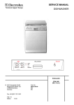
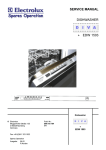
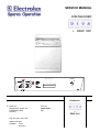
SERVICE MANUAL
DISHWASHER
+ EDW 1001
FAVORIT
, 17(16,9
1250 $/
30 MINUTEN
=(,7
9 25:$+/
4 8, &.
K
5(,1,*(1
K
752&.1(1
K
(1'(
(,1 $86
1250 $/
9 25
%,2
63h/ (1
6$ /=
./$ 563h/(5
Dishwasher
© Electrolux
Muggenhofer Straße 135
D-90429 Nürnberg
Germany
Fax +49 (0)911 323 1022
Spares Operation
Ausgabe:
09.02
R.Kurzke
Publ.-Nr.:
599 515 006
EN
+
EDW 1001
Index
1.
Control panel ..........................................................................3
2.
Dimensions.............................................................................3
3.
Components ...........................................................................4
3.1
Electronic ............................................................................... 4
3.2.
Circulation pump .................................................................... 4
3.3
Drain pump .............................................................................4
3.4
Flow heater ............................................................................4
3.5
Detergent dispenser ............................................................... 5
3.6
NTC-thermal sensor ............................................................... 6
3.7
Pressure switch ...................................................................... 6
3.8
Interference filter .................................................................... 6
3.9
Spray arms .............................................................................7
3.10
Drying fan ............................................................................... 7
3.11
Regeneration dosing with condensor ..................................... 8
3.11.1 Water softening/regeneration ................................................ 8
4.
5.
6.
4.1
4.2
Repair informations ................................................................9
Open the housing ................................................................... 9
Position of the components ....................................................10 - 12
5.1
5.2
5.2.1
5.3
Water course Scheme ............................................................ 13
All-Around Water Protection ..................................................14
Water intake ...........................................................................15
Water load steps .................................................................... 16 - 17
Draining .................................................................................. 18 - 19
6.1
6.2
6.3
6.4
6.5
6.6
6.7
6.8
6.9
6.10
6.11
6.12
6.13
6.14
Electronic ............................................................................... 20
Modifications EDW 1000 / EDW 1001 ................................... 20
In- and Output Elements ........................................................ 21
General .................................................................................. 22
Input-philosophy: Choose programs and options ................... 23
Input-philosophy: From program start to -stop ....................... 24
Input-philosophy: Delete - change - cancel ............................25
Input-philosophy: Displays .....................................................26
Operating errors and flow interruption ................................... 27
Servicefunction / Adjust water hardness ................................ 28
Servicefunction / Switching off the rinsing agent display ....... 29
Servicefunction / Manufactur ..................................................30
Servicefunction / Customer support .......................................31
Overview of service and customer support functions ............. 32
Overview of error displays...................................................... 33
7.
8.
Program steps ........................................................................ 34
8.1
8.2
09.2002 R.K.
Wirings ................................................................................... 35
electric circuit diagram ........................................................... 35
Wiring diagramn ..................................................................... 36
-2-
599 515 006
EN
1.
Control panel
Function buttons
Progamme buttons
2.
*
Delay start Indicator lamps
button
delayed start
Control lamps
Control lamps
Door handle
On/Off button
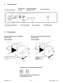
Dimensions
Build-in dimensions for Integrated
Dishwashers
Build-in dimensions for Built-Under
Dishwashers
ÖKO-FAVORIT
ÖKO-FAVORIT
* Appliances with
height
adjustable feet
Appliances with height-adjustable feet
Plinth height for appliances 820 mm high
100 - 175 mm
Plinth height for appliances 870 mm high
150 - 230 mm
Dimensions for Freestanding Dishwasher
Height
Width
Depth
85 cm
60 cm
60 cm
Height with worktop removed 82 cm
Feet adjustment 1 cm
09.2002 R.K.
-3-
599 515 006
EN
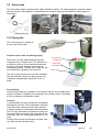
3. Components
3.1 Electronic
On electronic models, a micro processor controls all
components, this is done using triacs. The electronic also
memorizes all programme data.
The heating is switched by a relay on the electronic board.
3.2 Circulation Pump
The circulation pump is driven by an asynchronous motor with
an auxiliary winding. The auxiliary winding ist in circuit with a 3
mF capacitor. A tacho generator is used for speed control.
There are three speeds for rinsing.
2800 1/min, 2200 1/min, 1900 1/min, 1700 1/min, 1600 1/min,
Power output 50 W.
Wicklungswiderstände
Hauptwicklung 45 - 55 Ohm
Hilfswicklung
110 - 140 Ohm
Tacho
ca. 220 Ohm
Nur bei Ausführungen mit Deckensprüharm
3.3 Drain Pump
The drain pump is driven by a synchronous motor.
Power output 26 W.
Pump rate 15 l/min.
3.4 Flow Heater
The flow heater heats the water to the required temperature.
During the wash cycle, water is contantly passing through the
flow heater.
Power output
Resistor
Protector
Thermal fuse
05.2002 R.K.
2000 W
25 W
98 °C ± 5 K
260 °C
-4-
599 514
DE
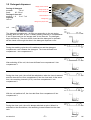
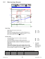
3.5 Detergent dispenser
Dosing of detergent
prewash
10 ml
wash
20 - 30 ml
Dosing of rinse aid
position 1 - 6
2 ml - 7 ml
Capacity
140 ml
display lack of rinse aid
dosing of rinse-aid
maximum filling level
outlet of rinse-aid
detergent tray
detergent tray for pre wash
coil
Spule
The detergent compartment 1 is filling corresponding to the set dosing
quantity when the door is open. Possibly existing rinse-aid in compartments
2 and 3 flows back into the storage tank of the rinse-aid. The detergent
trays are filled up. The door will be closed and the detergent for prewash
will be rinsed out through the slots in the detergent dispenser cover.
During the washing cycle the coil is switched on and the detergent
compartment cover releases the detergent. The rinse-aid flows from
compartment 1 into compartment 2.
EIN
AUS
Zeit
EIN
AUS
Zeit
EIN
AUS
Zeit
After switching off the coil, the rinse-aid flows from compartment 2 into
compartment 3.
During the rinse cycle, the coil will be switched on when the rinse is warmed
and the rinse-aid runs from compartment 3 into the rinse tank. At the same
time, the remaining rinse-aid (15 %) runs from compartment 1 into
compartment 2.
EIN
AUS
Zeit
EIN
AUS
Zeit
With the coil switched off, the rinse-aid flows from compartment 2 into
compartment 3.
During the rinse cycle, the coil is always switched on twice. When it is
switched on the second time, the remaining rinse-aid flows into the rinse
tank.
05.2002 R.K.
-5-
EIN
AUS
Zeit
599 514
DE
3.6 NTC-Temperature Sensor
Temp.
Resistor
10°C
25°C
60°C
90°C
9653 Ohm
4843 Ohm
1204 Ohm
445 Ohm
3.7 Pressure Switch
The pressure switch controls the water level.
Without water, contact 11 - 12 is closed.
fN
Switch point with level
Reset point with level
65 mm Ws
45 mm Ws
The pressure switch is not adjustable.
3.8 Interference Filter
The interference filter is connected in the terminal board parallel to the mains feed.
05.2002 R.K.
-6-
599 514
DE
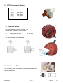
3.9 Spray arms
The new cutlery basket is placed at the upper diswasher basket. The celling sprayarm sprays the water
directly onto the cutlery basket and tguarantees an excellent washing result with the cutlery placed in
that basket.
Celling spray arm
upper spray arm
lower spray arm
3.10 Drying fan
The new drying fan is located at
the top on the rinse tank.
Function mode of the condensing drying
Rinse tank, fan and regenerating dosing with
condenser form a closed circuit. The humid air is
sucked from the top of the rinse tank and blown
through an air guide between rinse tank and
regenerating dosing. Thereby the air gets dry and
the condensate is guided to the drain tub.
air guide for
condenser
fan
rinse tank
ventilation
drain tub
The dry air gets through the rinse tank ventilation
into the rinse tank. During the drying phase, the
condenser is additionally cooled with 1 liter of
water.
Active Drying
Active Drying means the ventilation of a container without any movable parts
A plastic container is clipped into the opening in the container cover, from where
a hose is passed to the appliance base.
Function
A small quantity of moist air and some condensate
emerge from the hose. The condensate is collected
in the base side sections where it will evaporate.
If a larger quantity of condensate should be present
(due to many subsequent programme cycles) the
hose end will be immerged, thus stopping both the
convection and the condensating process in the
hose.
Flooding of the sections is therefore excluded. Only
very little moist air will be present.
05.2002 R.K.
-7-
599 514
DE
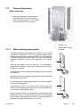
3.11
Regenerating dosing
with condenser
With every filling step, the condenser
cools down due to the cold incoming
water. Therefore another 1 liter of water
is required during the drying cycle.
3.11.1
Water softening/regeneration
The water softening can be adjusted in 10 levels. The incoming
water flows until positon 5 to 85 % through the softener which
works according to the ion exchange principle. The ion exchanger
is filled with small epoxy resin balls. The resins exchange the
hardness constituents (calcium and magnesium), for sodium
ions.
When all the sodium ions are used up, it is necessary to
regenerate the softener. This is done by flushing a brine solution
through the softener.
1.
softener unit
2.
regeneration dosage
chamber
2
1
Afterwards the softener is washed out with fresh water and is now
fully effective.
Depending on the water hardness, regeneration is only necessary
after several wash cycles.
The remaining 15 % of water flow through the rinse tank ventilation
directly into the appliance.
From setting of level 6, the whole water flows through the
softener. For this purpose you also have to set mechanically from
0 to 1 with the regenerating dosing.
With the setting of level 9, it is additionally regenerated after the
washing in a rinse cycle. With the settings 1 to 8, it is regenerated
after the final rinse depending on need. The softening system is
designed for a water hardness of up to 70 °dH.
05.2002 R.K.
-8-
2
1
599 514
DE
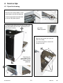
4. Service tips
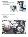
4.1 Open the housing
1
Remove the screws (Abb.1) of the
upper plate on the left and right side.
2
Push the upper plate in front direction
to remove the plate (Abb.2).
To remove side panel remove fixing screws, pull
the panel away from the rear, and gently out of
the front trim. (pic.1).
You need
Torx epuipment
1
Remove the screws (1) to pull the
outer door away.
To remove the panel, remove the
fixing screws (2) .
2
Removing the
cover plates of the
base area, remove
these screwst
(Abb1+2).
2
05.2002 R.K.
1
3
-9-
599 514
DE
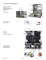
4.2 Position of Components
3
Detergent dispenser (1)
Spray arms (2)
Roof-mounted shower (3)
Salt container (4)
Filter (5)
4
5
2
1
Type plate (6)
6
1
On/Off-Switch (1)
Electronic (2)
2
1
Electronic
Panel (1)
Detergent dispenser (2)
2
Thermal sensor (3)
Drain pump (4)
Pressure switch (5)
3
05.2002 R.K.
- 10 -
4
5
599 514
DE
5
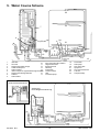
Back side view
-
Flow heater (1)
Terminal box (2)
-
Inlet hose (3)
Drain hose (4)
-
Water inlet for above spray arm (5)
1
4
2
3
1
Removing the detergent dosage chamber:
-
disengage locking tabs (1), disconnect hoses (2)
holding the top of the chamber, pull upwards
disengaging it from the softener.
2
Removing the softener unit :
-
remove the securing nut located under the salt cap.
press softener (1) down and remove it through the front
from the base area
CAUTION if accessible release reed switch.
1
05.2002 R.K.
- 11 -
599 514
DE
Removing the base :
-
remove side panels, rear panel and plinth panel
gently release base fixing clips with a screwdriver (figure)
take off base carefully and release circulation pump,
electronic and heater relay
disconnect the float switch
With
-
base removed, following components are accessible:
Drain pump (1)
Circulation pump (2)
Flow heater (3)
Temperature sensor / Turbidity sensor (4)
Pressure switch (5)
4
1
5
2
3
05.2002 R.K.
- 12 -
599 514
DE
5. Water Course Scheme
2
22
3
21
7
4
15
23
24
21
1
12
6
5
11
8
9
18
16
10
19
14
1
2
3
4
5
6
7
8
9
20
17
Inlet valve
10
Air break
11
Regeneration water dosage
12
Overflow safety level
13
Safety overflow
14
Inlet to sump from regeneration dosage chamber
15
Regeneration dosage chamber
16
Softener
17
Salt container
Non-return valve salt container
Regeneration valve
Safety inlet hose
Base tray
Float switch
Pressure switch
Filter
Circulation pump
18
19
20
21
22
23
24
13
Flow heater
Drain pump
Non-return valve
Spray arms
Roof-mounted shower
Tub vent
Sump assembly
ohne
Sicherheitszulaufschlauch
Ausführung:
Kurze Regenerierdosierung
09.2002 R.K.
- 13 -
599 515 006
EN
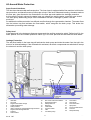
All-Around Water Protection
Aqua-Control Inlet Hose
The inlet hose has a double-wall construction. The inner hose is equipped with a flow restrictor built into the
tap connection, and has a flow rate of 4 litres per minute. If the inner tube starts bursting, the water reaches
the floor pan, gets diverted to the float switch in the floor pan and enables the drainage protection.
In this case the electric valve at the water hose get voltage free and the water connection gets locked.
The drain pump additionally pumps off the dishwasher so that no damage by water could be
produced.
An additional overflow protection is a defined overflow through the regeneration chamber. The water flows
into the bottom tray and activates the float switch, which energises the drain pump. This drains the
dishwasher preventing water damage.
Safety level
If the water level in the detergent dispenser transcends the overflow protection switch Safety level(4), the
water passes over the overflow protection switch (5) in the floor pan and also activates the float switch.
Leakage Protection
The anti-flood switch in the base tray will activate the drain pump and drain the water from the tub in the
event of an internal leakage. If the float switch is activated, all electric components are switched off except
the electronic and the drain pump.
2
22
3
7
21
23
4
15
24
1
12
6
5
11
8
9
17
10
18
20
19
13
1
2
3
4
5
6
7
8
9
16
14
Inlet valve
Air break
Regeneration water dosage
Overflow safety level
Safety overflow
Inlet to sump from regeneration dosage chamber
Regeneration dosage chamber
Softener
Salt container
09.2002RKR.K.
03.03.
10
11
12
13
14
15
16
17
Non-return valve salt container
Regeneration valve
Safety inlet hose
Base tray
Float switch
Pressure switch
Filter
Circulation pump
- 14 -
18
19
20
21
22
23
24
Flow heater
Drain pump
Non-return valve
Spray arms
Roof-mounted shower
Tub vent
Sump assembly
599 515 006
EN
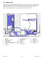
5.2
Water Inlet
The water flows into the regeneration dosage chamber (7) via inlet valve (1), over air break (2), into
regeneration dosage chambers (3) into softener (8). At this point the water divides. 1/4 of the water
enters the tub through the vent (23). 3/4 of the water enters the sump (24) through hose (6).
The level control chamber built into the sump operates the pressure switch (15).
2
22
3
7
21
23
4
15
24
1
12
6
5
11
8
9
Inlet valve
10
Air break
11
Regeneration water dosage
12
Overflow safety level
13
Safety overflow
14
Inlet to sump from regeneration dosage chamber
15
Regeneration dosage chamber
16
Softener
17
Salt container
09.2002 R.K.
17
20
18
10
19
14
13
1
2
3
4
5
6
7
8
9
16
Non-return valve salt container
Regeneration valve
Safety inlet hose
Base tray
Float switch
Pressure switch
Filter
Circulation pump
- 15 -
18
19
20
21
22
23
24
Flow heater
Drain pump
Non-return valve
Spray arms
Roof-mounted shower
Tub vent
Sump assembly
599 515 006
EN
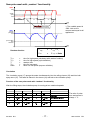
5.2.1
Water load steps (Example)
s tatic water
load
dynamic water
load
to level
max. 4
r epetitions
with level contr ol
T imeout 1
T imeout 2
speed
in U /min
targets peed
10 S ek.
5 S ek.
5 S ek.
20 S ek.
1600
time
in S ek.
0
water
in L
level check:
level check:
water failure dis played
if level not r eached!
water failure dis played
if level not r eached!
3,6 - 4
dynamic
water load
ca. 1,6
s tatic
water load
time
in S ek.
0
valve
filing
filling is pos sible
on
time
off
in S ek.
Static filling
-
Static filling until pressure switch point.
failure code:
If this point isnt reached after max. 2 minutes (Timeout 1), a
failure code is displayed and the program is stopped. The program phase display PPD-LED LD9 is blinking.
LD9
LD10
LD11
Dynamic filling
-
10 seconds filling at reduced circulation pump speed
5 seconds pause
10 seconds filling at reduced circulation pump speed
filling with increasing circulation pump speed. As soon as the
target speed has been reached, it is filled up to the pressure
switchpoint.
Failure code:
If this dynamic switchpoint isnt reached within total 4 minutes
(Timeout 2), the dynamic filling can be repeated 3 times. Only
after non-successful repeating 3 times, a failure code is displayed
and the program is stopped. The PPD-LED LD9 is blinking.
SXOVHZDVK
09.2002 R.K.
SXOVHPLQ
VHF
VHF
VHF
LD9
LD10
LD11
*)
The target
speed is
dependent on
the subsequent
pulse wash.
3DXVHPLQ WDUJHWVSHHGLQG\QDPLFILOOLQJ
VHF
PLQ
VHF
PLQ
VHF
PLQ
- 16 -
599 515 006
EN
New pulse wash with random functionality
speed
in U /min
2800
var iable
s peed
1600
20 S ec.
s tar t-r outine
T high,r
T low
T high,r
T low
T high,r
time
in s ec.
0
-function
*) The variable speed is
1600 1/min at the
moment and equal to all
appliances.
T high,r = time (high s peed) + r andom time
water
in L
dynamic
pulse was h
level
pr ess ur e s witch
point
water level
time
in s ec.
0
Random-function
Thigh,r
Thigh
Tr
Tlow
Ratio
=
=
=
=
=
T
high, r
=
T
high
+ Tr
T
low
=
T
high, r
+ Ratio
time for high speed (calculated with random funktion)
time for high speed (cycle definition)
random time
time for low speed
factor for low speed (eeprom definition)
Circulation
The circulation pump (17) pumps the water simultaneously into the ceiling shower (22) and into both
spray arms (21). The water is filtered in the sieves (16) and led to the circulation pump.
Function of the new pulse wash with random functionality
After the filling steps, the circulation pump is running at two rotational speeds.
3XOVHWLPHPLQ
3XOVH :DVK
'H ILQLWLYH7LPH
VHF
5D QGRP7LPH
VHF
3DXVHPLQ
'HILQLWLYH 7LPH
5DQGRP7LPH
VHF
8VH Z LWK:DVK&\FOHV
SUHZDVKLQWHQVLYH
ZDVKLQWHQVLYH
VHF
VHF
VHF
ZDVKDQGLQWHUPHGLDWHZDVK
The ratio of pulse
time and pause is
always 1 : 5.
SUHZDVKQRUPDO
09.2002 R.K.
VHF
VHF
VHF
- 17 -
ULQVH
599 515 006
EN
5.3 Draining
During the wash cycle the water is pumped out at various stages. First the draining water cleans the
filters (16). The filters are open at the bottom which allows any soilage to be rinsed off sufficiently.
There is a non-return valve (20) at the inlet connection to the drain pump (19). This valve prevents the
water
2
22
3
7
21
23
4
15
24
1
12
6
5
11
8
9
Inlet valve
10
Air break
11
Regeneration water dosage
12
Overflow safety level
13
Safety overflow
14
Inlet to sump from regeneration dosage chamber
15
Regeneration dosage chamber
16
Softener
17
Salt container
09.2002 R.K.
16
17
20
10
19
14
13
1
2
3
4
5
6
7
8
9
18
Non-return valve salt container
Regeneration valve
Safety inlet hose
Base tray
Float switch
Pressure switch
Filter
Circulation pump
- 18 -
18
19
20
21
22
23
24
Flow heater
Drain pump
Non-return valve
Spray arms
Roof-mounted shower
Tub vent
Sump assembly
599 515 006
EN
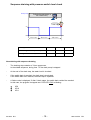
Sequence draining with pressure switch level check
dr ain pump
1 dr aining s equence
with var iable timing
level check!
on
off
T 1 (var iable)
T 2 (var iable)
'UDLQ&\FOH
T 3 (var iable)
7
7
7
)LUVWGUDLQLQJEHIRUHHYHU\ZDVKF\FOH
VHF
VHF
VHF
'UDLQLQJDIWHUWKHZDVKF\FOHV
VHF
VHF
VHF
New draining with sequence draining
-
The draining step contains of 3 time sequences.
In the middle sequence, during time T2 the drain pump is stopped.
-
At the end of the drain step, the water level is checked.
-
If the switch back is reached, the drain step is terminated.
If the switch back isnt reached, the drain step is repeated.
-
A failure code is displayed, if after 2 drain steps, the switch back couldnt be reached.
In this case, the program is stopped and PPD-LED LD10 is blinking.
LD9
LD10
LD11
09.2002 R.K.
- 19 -
599 515 006
EN
6.10RGLILFDWLRQVIURP(':WR(':
Author: Doris Reiß WPD/EP - Basis EDW1000 (C0901m10.s2)
1R *URVV'HVFULSWLRQRIWKH&KDQJH
'HWDLOHG'HVFULSWLRQ
1
Fan control
2
Program Reset during Drying in case of power failure
(switching ON/OFF)
3
Water hardness setting procedure changed.
Operation Manual needs to be adapted for existing machines.
4
Rinsing agent deconnectable
You should not make the user aware of filling up
(Clip handle as for water hardness setting, but key 2)
for cleansing agent with integr. rinsing product. Rinsing agent rinsing agent, if this is already integrated in the
cleansing agent.
LED is deactivated.
Operation Manual needs to be adapted
Automatic half-charge detection
Limit and correcting factors in the EEPROM
Automatic Start for Super Simple
only when switching ON/OFF by use of main switch
Selection of two programs by one key only
Super Simple only (toggle function)
You can define the program for automatic start in
the EEPROM
8
Superwash
120 min
9
Intensive program 80 min
Only with ZM
5
6
7
10 Eat Load Run program
Point of rinsing with programs for new drying modified from
program start to Drying.
Wasserzulauf Trocknen wegen neuer Reg-dos
12
(New Water system)
New Reg-dos (New Water system) 13
Change of rinsing to 2 litres in the EEPROM
With half-full detection - 5°C during Wash
14
not with Intensive)
As with ET/ET plus by means of heating speed
Duration 30 min
11
1 l water admission for drying support
With half-full detection, the temp. is reduced by 5K
during Wash.
15 New energy-saving program for BAB
16
17
18
19
20
21
22
23
Adaptation of minimum program durations for hot water
connection.
Intensive and normal programs without impulse rinsing for ZM
as well
5HPRYHG
Alternating spray beam drive by ball
5HPRYHG
Alternating spray beam drive by ball with half-full
5HPRYHG
Tablets option no longer possible
5HPRYHG
Subprograms no longer required were canceled.
5HPRYHG
Change of manufacture testing program for ZM
5HPRYHG
Readable in the EEPROM
Program counter over the life cycle
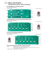
6.2 ,QSXWVDQG2XWSXWV
$UUDQJHPHQWRINH\V/('
VDQGODPSV
IRU'*1DSSOLDQFHVRI6*$GHVLJQ$(*
with vertical key arrangement
left hand panel side
right hand panel side
S1
S4
L D4
L D1
S5
S2
L D5
L D2
S3
L D8
L D9
L D7
L D10
L D6
L D11
S6
L D13
L D12
L D3
L D0
S0
L D14
)RU'*1DSSOLDQFHVRI,*$GHVLJQ$(*DQG2(0YDULHWLHV
with horizontal key arrangement
left hand panel side
L D1
right hand panel side
L D2
L D3
L D4
L D5
L D8
L D9
L D7
L D10
L D6
L D11
L D0
L D12
S1
S2
S3
S4
S5
L D13
S6
S0
L D14
IRU6RODURDQG6FKZDQGHQDSSOLDQFHV
with horizontal key arrangement
left hand panel side
right hand panel side
L D0
L D1
L D2
L D3
L D4
L D5
L D8
L D9
L D7
L D10
L D6
L D11
L D12
S0
S1
S2
S3
S4
S5
S6
L D13
L D14
*HQHUDOO\DYDLODEOHNH\VDQG/('
VPLQLPXPVWDQGDUG
Keys
S0 (ON/OFF), S1, S2, S3 as programming keys
If the 3 programming keys are not placed on S1 - S3, observe the revisions made to maintenance or customer service
programs respectively, and also the hardness range selection!
LED’s / Lamps
LD0 (ON/OFF), LD1, LD2, LD3
6.3*HQHUDO
l
(TXLSPHQWLQSDQHODUHD
(refer to panel drawings on page B 1)
w Separately arranged ON/OFF key S0
w 6 keys S1 to S6 for selection of programs or options
All keys can be freely assigned without restriction due to programming of the model at issue
Keys S1 to S3 and the associated LED’s should usually be available
required for maintenance function control)
w 3-step program flow display (PAA) with LED’s
Denomination of LED’s "Wash" - "Dry" - "End"
Available on certain models
w 3-step start preset time with display via LED’s LD6 to LD8
Time grades are stored in the EEPROM and can be freely assigned without restriction due
to programming of the model at issue
It is necessary, however, that the 3 selected times are between 1 hours and 15 hours.
w LED display for salt
w LED display for rinsing agent
l
$YDLODEOHSURJUDPRSWLRQVIRUVHOHFWLRQ
w
w
w
w
w
l
Start preset time
Superwash
Half load "small quantity"
Temperature increase and/or temperature reduction
Additional rinsing cycle
0LVFHOODQHRXV
w
w
w
w
w
w
w
Regeneration on demand / Water hardness setting and display on the control panel
Rinsing agent display can be switched off by customer depending upon the model
Manufacture check program
various customer support functions (error memory, individual actuator control, LED test)
Rating of the appliance for max. energy label ABC
optional with and without blower drying
Aqua-Control-System in various models
Depending upon electrical and mechanical components and the associated programmation of the model
l
.H\YHUVLRQ
The ON/OFF key S0 is made as separate mains switch with "exceeding stroke" function.
All other available keys S3 to S6 are keys on the printed circuit board.
l
$FNQRZOHGJHPHQWVDQG'LVSOD\V
All key acknowledgements and other displays are displayed by the LED’s.
Only the ON/OFF key is provided with a glow lamp instead of a LED display
This indicates the operational status of the appliance (appliance is switched ON or OFF).
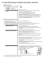
6.4,QSXW3KLORVRSK\3URJUDPDQGRSWLRQVHOHFWLRQ
$SSOLDQFHVWDUWXS
w Switch the appliance ON by use of ON/OFF key S0
w Anzeige LD0 bei Ein/Aus-Taste leuchtet.
© Appliance is in prestart mode.
© All program and optional keys are enabled and can be selected
w Selection of start time anytime
possible
w Start preset time by use of the key which is defined accordingly
This key has no acknowledgement LED.
w Activated start time displayed by means of 3 LED’s
Only one of the start preset time LED’s can be lit.
w Selection by rotational system (e.g. 3h .. 6h .. 9h .. OFF .. 3h ..)
w Switch-over or switch off of start preset time is possible anytime (all
start preset time LED’s dark) during the total run of the start time
w Since no rinsing cycle has been selected, the preset value of start
preset time is maintained and flashing.
3URJUDPVHOHFWLRQ2SWLRQVHOHFWLRQ
w
w
w
w
w
The desired rinsing cycle is set by pressing the corresponding program key.
LED of selected cycle key is lit.
The operator can switch the program over within 6 sec or add one or more options.
During this phase, all PAA-LED’s pertaining to the program are flashing, but not the LED backlit by "END".
Any options or the start time preset can be added only until the start of the program proper!
w 2SWLRQVDUHDYDLODEOH
w Press the desired option key
w Acceptable are only the defined combinations admissible
w If the option selection is admissible, the program key and option key
LED’s are lit
w It is possible to select another option within 6 sec.
w 6WDUWWLPHSUHVHWLVDYDLODEOH
w Set the start time preset by pressing the respective defined key
w Start time activated is displayed on 3 LED’s
Only one of the start preset time LED’s can be lit.
w Selection by rotational system (e.g. 3h .. 6h .. 9h .. OFF .. 3h ..)
w 6 seconds after the last action on the key, the timer for preset time is
started.
w Within those 6 seconds, the associated program key LED is lit.
w During this phase, all PAA-LED’s pertaining to the program are flashing,
but not the PAA-LED backlit by "END".
w During the sequence of start preset time, the program key DEL is
permanently lit.
PAA indication goes dark during this period.
w It is anytime possible to switch over or off the start preset time (all start
preset time LED’s are off)
druing the whole of the sequence of the start time.
w Sequence of the selected start time w The start time selected is counted backwards from the set value
until reaching Zero hours. Then the program is started automatically.
(see description page B 4 / "Program start")
L D8
L D7
w Indication is updated accordingly.
9h
L D6
w Display of start times:
9h to 6h - LED LD6
L D8
L D7
6h
6h to 3h - LED LD7
L D6
3h to 0h - LED LD8
L D8
0h / Start - all LED’s "off"
(Other definitions possible depending upon each model!)
3h
w Every pushbutton operation during the 6-second operation period will reset the timer for program start
proper (keys are then blocked) back to 6 seconds.
L D7
L D6
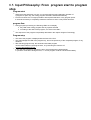
6.5 ,QSXW3KLORVRSK\)URPSURJUDPVWDUWWRSURJUDP
VWRS
3URJUDPVWDUW
w When the preset start time runs out, or 6 seconds after the last pushbutton operation of
a program or option key, the rinsing program selected is started automatically.
w From this moment it is no longer possible to add a preset start time or any program option.
It would be necessary to completely restart the machine to enter a new preset start time!
SURJUDPIORZ
w During program processing, the following LED’s are on display
© Key LED of the rinsing program and any options selected
© According to the state of the program, one of the PAA LED’s
w The sequence of the program is separately described in the chapter Program Technology
3URJUDPVWRS
w The end of the program is displayed with the PAA LED "End".
w The acknowledgment LED of the program key, and of the option key of the completed program, if any,
remain lit.
w After reaching program stop, the stored and executed program
can be cleared either by opening the door, or by switching the machine off
by use of the ON/OFF key S0.
w If you clear the program by opening the door, the machine will be automatically
in "prestart" mode after closing the door, i.e. a new program could be selected immediately.
6.6,QSXW3KLORVRSK\FOHDULQJFKDQJLQJFDQFHOOLQJ
&OHDULQJDSURJUDPP
w You can clear a rinsing program selected or already started at any time.
w For this, press the key of the selected rinsing program until
the associated key LED goes dark (after approx. 2 secs).
© During this time, the associated key LED and the LED’s of any selected option keys are lit.
w The rinsing program is canceled and cleared.
© All LED’s of all program and option keys, and also the PAA LED’s will go dark, too.
© Only the indicator lamp LD0 at the ON/OFF key remains lit.
w The machine is now back in the prestart mode.
(see description page B 3 / "Switching ON the machine")
&KDQJLQJWKHSURJUDPZKHQWKHSURJUDPKDVDOUHDG\VWDUWHG
w
Both "Clearing the program" and then "restarting" the desired program are possible (see above)
w Direct change-over during operation is not possible.
,QWHUUXSWLQJWKHSURJUDP3DXVH)XQFWLRQ
w You can interrupt the program for any period of time by use of the ON/OFF key S0 without any losses.
This is equal to a "Pause" Function. The same is true for any interruption by opening the door.
w No clearing function is integreted into the ON/OFF key S0!
w Whenever the program is interrupted with the ON/OFF key, all indications go dark.
w After restarting by pressing the ON/OFF key or by opening the door, the program flow is continued
at once without need to press any button.
I Note:
With program sequences where the recycling pump is controlled, this one is operated
directly upon the startup for about 20 seconds at reduced speed. N
w All indications and acknowledgements appear in the same status as before the break
I $WWHQWLRQ: This function is only applicable until the start of the program section "Drying".
w From the program section "Drying" the following is true:
w If the machine is stopped by pressing the ON/OFF key S0.
the program is cleared.
© All displays go dark.
© If you restart the machine by pressing the ON/OFF key S0, it will be automatically,
after closing the door, in "prestart" mode, so that you could immediately select a new program.
l
:KDWKDSSHQVZKHQRSHQLQJDQGFORVLQJWKHGRRU"
w 0DFKLQHLVVZLWFKHG21DQGLVLQSUHVWDUWPRGH
w After opening the door, all indications on the panel are maintained.
Full power supply to the electronic system is ensured as long as the machine remains switched ON.
w 7KHGRRULVRSHQHGGXULQJDSURJUDPLQSURFHVV
w By opening the door, you can interrupt the program without losses for any period of time.
This is equal to a "Break/Pause" function.
w After opening, all displays on the panel are maintained so long as the machine remains
siwtched on by means of the ON/OFF key S0.
w After closing the door, the machine immediately starts up, the program flow is continued.
6.7 ,QSXW3KLORVRSK\'LVSOD\V
l
'LVSOD\RISURJUDPSURJUDPVHTXHQFHVWDUWWLPHSUHVHWDQGLQIRUPDWLRQ
w All displays are executed as LEDs and available depending upon the model.
w They are subdivided into 4 different types:
1.
2.
3.
4.
Program selection and option displays
Program flow displays
Start time preset LED’s
Information displays
w 3URJUDPVHOHFWLRQDQGRSWLRQGLVSOD\V
© Over or next to a program or option key, there is always a corresponding LED
for acknowledging the selected function (not applicable for start time preset).
© They are continuously lit during the whole program flow.
w 3URJUDPIORZGLVSOD\3$$
© The program flow display contains of a maximum of 3 LED’s
© The position of the LED’s depends upon the model programming.
With vertical key arrangement, output is by the LED’s LD6 to LD11, LD13 and LD14,
with horizontal key arrangement there is additionally LED LD12.
© At present, PAA is assigned to the LED’s LD9 through LD11.
© According to the program start, the associated LED will be lit permanently during the entire program flow.
w /('IORZGLVSOD\IRUSUHVHWVWDUWWLPH
© LED display for start time preset contains of a maximum of 3 LED’s
© The position of the LED’s depends upon the model programming.
With vertical key arrangement, output is by the LED’s LD6 through LD8 and LD9 through LD11,
with horizontal key arrangement there are additionally LED’s LD12 through LD14.
© At present, start time preset is assigned to the LED’s LD6 through LD8 and is defined as follows:
LD6 = 9h / LD7 = 6h / LD8 = 3h
© According to the time processed, the associated LED will be lit permanently until program start.
w ,QIRUPDWLRQGLVSOD\V
© These LED’s are permanently lit from switching the machine on by use of ON/OFF key until
the moment of actual program start. These LED’s will also be lit after reaching program stop until the
machine is switched off.
© The display LED’s will go dark during the entire program flow!
w /('GLVSOD\6DOW
© The position of the LED depends upon the model programming.
It can be assigned to any LED not occupied with a program or option key.
© At present, the LED Salt is assigned to the LED’s LD13 or LD14.
© "ON" when salt is lacking
© Goes dark after filling up the salt (depending upon the dissolution of the salt, it may take some time
until the LED goes dark).
I Note:
LED display Salt goes dark when hardness range "WH1" is set
(no regeneration required)
w /('GLVSOD\5LQVLQJDJHQW
© The position of the LED depends upon the model programming.
It can be assigned to any LED not occupied with a program or option key.
© At present, the LED Rinsing agent is assigned to the LED’s LD13 or LD14.
© "ON" when rinsing agent is lacking
© Goes dark after filling up the rinsing agent
I Note:
Rinsing agent display can be totally switched off by the customer, depending upon the model.
(see description page B9)
6.82SHUDWLQJ(UURUVDQG)ORZ,QWHUUXSWLRQ
l 6LPXOWDQHRXVSUHVVLQJRIRUPRUHNH\V
w In practice, it is not possible to press several program keys exactly simultaneously
in view of electronic detection.
l .H\SUHVVHGWRRORQJZKHQSURJUDPLVLQSURFHVV
w If you press a program key for more than 3 seconds, this may cause
the rinsing program to be cleared.
(see description page B 5 / item "Clearing the program" )
w If any option key is pressed longer, this will be of no influence for the program flow.
These buttons are locked after program start.
l (UURUVGXULQJSURJUDPIORZ
(see description page B13)
w
Display by flashing program key LED’s and flashing PAA LED’s, depending each time
on the coding (see Table). LED’s of any option keys selected are lit.
8VHUHUURUV:DWHUWDSFORVHG3XPSFORJJHG
w If the error occurring is a user error, the machine automatically changes over
to "Pause Mode".
w If any error is detected, for instance "Water tap closed", the program is stopped at this place.
w
w
w
w
The machine will wait until the error is remedied (if possible).
In order to continue the program it will be necessary, in this case, to press the ON/OFF key.
The program is continued without transition at this place. No program losses will occur.
There is no need to clear the program.
0LVFHOODQHRXVHUURUV
w All other errors which are coded by means of the PAA LED’s, partly visible for the Customer,
are described in detail in the Table on page B12.
l 3RZHUIDLOXUH
w In case of power failure, the machine will behave in the same way as when switched off
w
w
w
by pressing the ON/OFF key.
(see description page B 5 / item "Interrupting the program & Break/ Pause function" )
When the power is back, the machine will behave in the same way as when switched on by pressing
the ON/OFF key.
The program is continued without transition at this place. No program losses will occur.
You need not press any key for the program to continue without transition after power failures.
I $WWHQWLRQ: This function is only applicable until the start of the program cycle "Drying".
From the start of the program cycle "Drying", the program will be stopped in case of power failure.
(see description page B 5 / item "Interrupting the program & Break/ Pause function" )
6.9 6HUYLFH)XQFWLRQ:DWHU+DUG
GQHVV6HWWLQJV
:KHQFDOOLQJVHUYLFHIXQFWLRQVJHQHUDOO\QRULQVLQJSURJUDPPD\
\EHVHOHFWHG
General Information
Calling / Modifying / Storing the Hardness Range Value
w Setting and adjusting the water hardness range is identical
1.
&DOOLQJWKHIXQFWLRQ:DWHUKDUGQHVVVHWWLQJV
S1
with all designs and/or key arrangements.
S2
w Always use the keys S0, S1 and S2, independently
2.
of their model-related program assignment.
blinken
L D1
L D2
S1
L D0
S2
S0
L D1
Tastenanordnung
senkrecht
L D2
S1
L D0
S2
3.
L D 1L D 2
L D0
S1 S2
L D0
L D1
L D2
S0
Tastenanordnung
waagrecht
S1
4.
5s ek . leuchten
L D0
L D1
S0
5.
*HQHUDOO\DSSOLFDEOH
w Key S1 is ALWAYS the "Water hardness range key"
w In the works, hardness range value WH3 has been preset.
w With setting „WH1“ no regeneration is usually carried out.
No adding of salt is required.
Any salt LED available will not be activated.
w Table of hardness range values:
Einstellung
Wasserhärte
Anzeige
mit LED LD1
WH 5
41 - 50 dH
5x blinken
WH 4
30 - 40 dH
4x blinken
WH 3
19 - 29 dH
3x blinken
WH 2
4 - 18 dH
2x blinken
WH 1
unter 4 dH
1x blinken
3x blink en
L D0
L D1
&KDQJLQJWKHSUHVHWKDUGQHVV
$
6.
pr o T as tendr uck
5s ek . Aus
L D0
L D1
A.
the function "Rinsing agent stop" is programmed
on a certain machine model.
If the backlit function is not available on a certain
model, the respective LED is switched off in the mode Service
Functions.
L D1
S1
7.
%
&
3x blink en
L D0
L D1
B.
Wieder holung der bl ink enden
Was s er här te-Anz eige bis ...
C.
5s ek . leuchten
Press the key S1 to modify the
hardness range. The value is increased in
rotating manner.
After pressing the key, the key LED LD1 will
go dark for about 3 seconds.
The new value is then displayed by coded
flashing of LED LD1.
L D1
X+1x bl ink en
L D1
L D0
*HQHUDOH[SOLFDWLRQVWRNH\/('/'
w This key LED goes on or flashes only if
Press keys S1 and S2 simultaneously and ...
... Keep them pressed until the machine is switched on
with the ON/OFF key S0. For acquittal, the respective key LED’s
LD1 and LD2* are flashing (LD2* is only flashing if rinsing agent stop has be
programmed - see explanation opposite)
Press the key S1 in order to call the water hardness function.
The acquittal LED LD1 lights up for 5 seconds.
Now the hardness range setting is displayed by
the key LED LD3 flashing:
(In the example left, WH3 is displayed by 3 times flashing)
This LED will then go dark for about 5 seconds ...
The operation is repeated on display for a maximum of 60 seconds.
(3x flashing – 5 sec pause – 3x flashing – 5 sec pause – etc.)
Further sequence as described under 6./ 7.
Any pressing of the key S1
will increase the hardness range rotatively.
(WH1, WH2 ... WH5, WH1, WH2, ...)
6WRUDJHRIWKHZDWHUKDUGQHVVVHWWLQJV
The hardness range selection is stored immediately upon each single input.
... AU S nach 6 0s ek . automatis ch
L D0
S0
... AU S dur ch manuelle B etäti gung über E in/Aus
([LWLQJWKHIXQFWLRQ
After 60 seconds after the last pushbutton operation on key
S1 or by switching the machine off by use of the ON/OFF key
S0, you automatically leave the special program.
6.106HUYLFH)XQFWLRQ6ZLWFKLQJRIIWKHULQVLQJDJHQWGLVSOD\
:KHQFDOOLQJVHUYLFHIXQFWLRQVJHQHUDOO\QRULQVLQJSURJUDPPD\EHVHOHFWHG
General Information
Aufrufen / Ändern / Speichern der Klarspüleranzeige
Function is not generelly available.
This function must be programmed in the software model.
1.
&DOOLQJDQGFKDQJLQJWKHULQVLQJDJHQWGLVSOD\IXQFWLRQ
S1
Press keys S1 and S2 simultaneously and ...
... Keep them pressed until the machine is switched on
with the ON/OFF key S0. For acquittal, the respective key LED’s
LD1 and LD2 are flashing.
L D0
Press the key S1 in order to call the "rinsing agent display" function.
L D0
The key LED LD2 is flashing.
When the rinsing agent display is activated, the END LED will
also be flashing.
The "END" LED position can vary depending upon the
model programming.
S2
w For deactivating or activating the rinsing agent dosage,
2.
you will need the keys S0, S1 and S2, independently of
their model-related program assignment.
w If rinsing agent dosage is activated, this will be displayed by
the LED’s LD2 and (position-independently) LED "END".
blink en
L D2
L D1
S1
L D2
S2
3.
4.
K lar s püler anz eige
ak tivier t
L D1
blink en
L D2
S2
LED
" E NDE "
blink t!
5.
bl ink en
L D0
S0
L D2
I
S2
L D0
Tastenanordnung
waagrecht
S1 S2
S2
L D0
S0
L D 1L D 2
L D0
S0
L D2
Tastenanordnung
senkrecht
S1
L D1
(see description page B 6 / item "Program flow display")
S2
6.
1RWH
This function is used to switch off the rinsing agent
display ONLY. It is generally not possible to switch off the
rinsing agent dosage.
If a certain model is not provided with rinsing agent LED,
this function cannot be displayed!
K lar s püler anz eige
aus
bl ink en
L D0
L D2
S2
LED
" E NDE "
aus !
By pressing key S2, you can now activate or
deactivate the rinsing agent display.
Rinsing agent display active:
Key LED’s LD2 and "END" LED are both flashing.
Rinsing agent display inactive:
KeyLED LD2 is flashing.
L D0
*HQHUDOO\DSSOLFDEOH
6WRULQJWKHVWDWXVVHWWLQJ
w Key S2 is ALWAYS the "rinsng agent key"
w In the works, rinsing agent display has been activated.
The setting is stored immediately upon each single input.
... AU S nach 6 0s ek . automatis ch
*HQHUDOH[SOLFDWLRQVWRNH\/('7
w This key LED only lights up or flashes, if
L D0
the function has been programmed on this machine model.
S0
If the backlit function is not available on a certain
model, the respective LED is switched off in the mode Service Functions.
... AU S dur ch manuel le B etäti gung über E in/Aus
([LWLQJWKHIXQFWLRQ
After 60 seconds after the last pushbutton operation on key
key S2 or by switching the machine off by use of the ON/OFF key
S0, you automatically leave the special program.
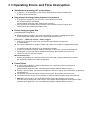
6.11 6HUYLFH)XQFWLRQV0DQXIDFWXUH
:KHQFDOOLQJVHUYLFHIXQFWLRQVJHQHUDOO\QRULQVLQJSURJUDPPD\EHVHOHFWHG
l
&DOOLQJWKH0DQXIDFWXUH7HVWLQJ3URJUDP
(see description page B 12)
Not for the use of final customers
w Press both program keys S1 and S3 simultaneously and keep them pressed
until the machine has been switched on by use of the ON/OFF key S0.
w As an acknowledgement that the function "Manufacture Test Program" is active, the key LED LD3 flashe
This LED will keep on flashing during the whole program cycle.
w Program starts automatically after about 3 seconds.
w The remaining program flow is identical to that of any Consumer rinsing program.
The usual rinsing program sequence is simulated.
w In the manufacte test program, regeneration is always carried out independently of the demand
w Program status is displayed by means of the PAA LED’s LD9 through LD11.
w In case of power failure, the test program is continued after approx. 3 seconds after the return of the pow
w You can stop the test program by opening the door.
w When the door is open, both the program key LED LD3 and the respective
PAA LED are lit.
w You can exit from the test program by again pressing on the key S3.
(also see description on page B 5 "Clearing the program")
w At the end of the manufacture test program, both the LED LD3 and the PAA LED "End" are lit.
l
6HWWLQJDQGUHFRJQLWLRQRIKHDWLQJSRZHU
w Heating capacity is included in machine model programming.
w All machines of series EDW1000 are of standard design 10A only.
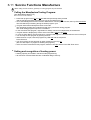
6.12 6HUYLFH)XQFWLRQV&XVWRPHU6XSSRUW
:KHQFDOOLQJVHUYLFHIXQFWLRQVJHQHUDOO\QRULQVLQJSURJUDPPD\EHVHOHFWHG
l
&RQWURORILQGLYLGXDODFWXDWRUV
(see description page B12)
w Press both program keys S2 and S3 simultaneously and keep them pressed
until the machine has been switched on by use of the ON/OFF key S0.
w As an acknowledgement that the function is active, the key LED’s LD1, LD2 and LD3 are flashing.
w Start the function by pressing the program key S2.
w The key LED LD2 will keep on flashing during the whole program cycle.
w The first actuator to be activated is automatically the valve. All other individual actuators can then be
called by pressing the program key S2 one after the other in the below-mentioned order.
w Each of the individual actuators is activated for the period of time indicated below. Then it
w
w
w
w
switches off automatically. The machine remains in a break mode until the next individual
actuator is called by pressing key S2 or you leave the whole function.
Each single actuator is displayed on the PAA LED’s in coded manner.
The order of activation is defined and rotative. It cannot be changed.
You can intentionally shorten the time of activation by pressing the key S2
even before the expiry of the stated period of time.
w Order of activation, ON duration and associated coding:
Ventil
Dos ier k ombi
U -P umpe
H eiz ung
Gebläs e
R eg.dos .
E -P umpe
20 s ek .
60 s ek .
60 s ek .
20 s ek .
60 s ek .
60 s ek.
60 s ek.
L D9
L D10
L D11
L D9
L D10
L D11
L D9
L D10
L D11
L D9
L D10
L D11
L D9
L D10
L D11
L D9
L D10
L D11
L D9
L D10
L D11
alle AU S
L D9
L D10
L D11
F or ts chaltung von Hand
w The function remains active until you switch if off by use of the ON/OFF key S0.
l
2XWSXW&XVWRPHU6XSSRUWHUURUPHPRU\
(see description pages B12 and B13)
w Press both program keys S2 and S3 simultaneously and keep them pressed
until the machine has been switched on by use of the ON/OFF key S0.
w As an acknowledgement that the function is active, the key LED’s LD1, LD2 and LD3 are flashing.
w Start the function by pressing the program key S1.
w The key LED LD1 will keep on flashing during the whole program cycle.
w Errors are displayed on the PAA LED’s LD9 through LD11 in coded manner.
(see page B13 / item "Error Display Overview")
w By further pressing each time on key S1, you can call the errors in rotative manner.
w Only the last three errors each occurred can be displayed.
w You can exit from the function only by switching the machine off by pressing the ON/OFF key S0.
werden.
l
&OHDULQJWKH&XVWRPHU6XSSRUWHUURUPHPRU\DQG/('7HVW
(siehe Beschreibung Seite B12)
w Press both program keys S2 and S3 simultaneously and keep them pressed
until the machine has been switched on by use of the ON/OFF key S0.
w As an acknowledgement that the function is active, the key LED’s LD1, LD2 and LD3 are flashing.
w Start the function by pressing the program key S3.
!! Warning: By starting this function, the error memory will be automatically cleared!!
w All LED’s provided on the panel (max. LD1 through LD14( will be lit simultaneously shortly (for abt. 1 sec).
The lighting up of all LED’s is repeated twice again with a break of 2 seconds in between each time. Then
only the program key LED of S3 will be flashing.
w You can leave the function in a shorter period of time only by pressing the ON/OFF key S0 and switching off
the machine.
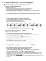
6.136XPPDU\RI6HUYLFHDQG&XVWRPHU6XSSRUW)XQFWLRQV
L D1
S1
L D4
S4
L D2
S2
L D5
S5
L D3
S3
L D1 2
S6
L D8
L D9
L D7
L D1 0
L D6
L D1
L D0
L D2
L D3
L D4
L D5
L D1 1
S1
S0
S2
S3
S4
S5
L D1 3
S6
L D8
L D9
L D7
L D1 0
L D6
L D1 1
L D1 2
L D1 3
L D0
S0
L D1 4
L D1 4
Tastenanordnung senkrecht
Tastenanordnung waagrecht
:KHQFDOOLQJVHUYLFHIXQFWLRQVJHQHUDOO\QRULQVLQJSURJUDPPD\EHVHOHFWHG$OOHZHLWHUHQ'DWHQVLQGGHP]XJHK|ULJHQ
DNWXHOOHQ3IOLFKWHQKHIW]XHQWQHKPHQ
Function
LED Display
Water Hardness
Setting
Switching Off the
Rinsing Agent
Display
Manufacture
Test Program
Individual Actuator
Control
Output Customer
Support Error
Memory
Clearing the
Customer Support
Error Memory
LED Test
Exiting the
functions
S1 + S2
then additionally
S0 (ON/OFF)
S1 + S2
then additionally
S0 (ON/OFF)
Í
LD1 and LD2
flashing
Í
LD1 and LD2
flashing
Í
Í
Selection resp. Start of Function
by key
LED Display
operation
LD1
lights up for 5sec.
S1
Í
S2
Í
Then display of new H value
by coded flashing
Short description/remarks
Í
For detailed description see page B 7
"Water hardness settings"
Í
For detailed description see page B 8
"Switching off the rinsing agent display"
Rinsing agent active:
LD2 and "END" flashing
Rinsing agent OFF
LD2 flashing
S1 + S3
then additionally
S0 (ON/OFF)
S2 + S3
then additionally
S0 (ON/OFF)
S2 + S3
then additionally
S0 (ON/OFF)
S2 + S3
then additionally
S0 (ON/OFF)
Í
LD3
flashing
Í
LD2 + LD3
Í LD1 +flashing
Í
Í
Program
start
after 3 sec.
automatically
S2
Í
Í
Í
S1
Í
LD2 + LD3
Í LD1 +flashing
Í
S3
Í
LD1 + LD2 + LD3
flashing
LD3
flashing
LD2
flashing
Í
Manufacture test program is carried out
automatically.
For detailed description see pag B 9
"Calling the manufacture test program"
Í
Order of activated actuators:
Valve > Dosing combination > Recycling pump > Heating
> Fan > Reg.dos > El.pump > all OFF
For detailed description see page B 10
"Individual actuator control"
LD1
flashing
For detailed description see pages B 10 / B
13
Í "Output Customer Support Error Memory" /
Error display coded via PAA
"Overview Error Displays"
LED’s.
The activation of this function will clear the
Customer Support Error Memory
3 times short lighting up of
all existing LED’s with an
approx.bBreak of 2
sec.each time.
Í
For detailed description see page B 10
"Clearing the Customer Support Error
Memory and LED Test"
$OO6HUYLFHDQG&XVWRPHU6XSSRUW)XQFWLRQVFDQRQO\EHH[LWHGE\ZD\RINH\6E\VZLWFKLQJ2))WKHPDFKLQH
Exception: Hardness Range Setting - You can leave this function also when after the last pushbutton operation on S1 60 seconds have passed.
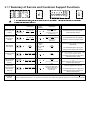
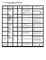
6.142YHUYLHZ(UURU'LVSOD\V
Applicable for EDW1001
(UURU1DPH
'LVSOD\
3$$/('
V
Error Display
visible for
Customers
Progr. LED flashing. Program stops.
After remedying the error, the
program can be continued by
pressing the ON/OFF key S0.
yes
flashing
yes
Pressostat has not reached point of
lit up
return after 2 pumping cycles.
permanently
Progr. LED flashing. Program stops.
After remedying the error, the
program can be continued by
pressing the ON/OFF key S0.
yes
Float switch detects water in the
lit up
trough (antirebounding time 2sec.)
permanently
Program is interrupted.
Valve is closed, and discharge pump
starts up for 1 pumping cycle
(approx. 1min). E
After remedying the error, the
program can be continued by
pressing the ON/OFF key S0.
L D9
Discharge pump
L D10
L D11
L D9
L D 10
Aqua-Control
L D 11
yes
flashing
L D9
Heating
L D 10
no
L D 11
L D9
NTC Sensor
L D 10
no
L D 11
Program is completed to the end
without activation of the heating
element!
All heating cycles generally take
45min.
Program is completed to the end
yes
NTC short circuit or break.
without activation of the heating
NTC is monitored between 1st filling element!
lit up
All heating cycles generally take
permanently to start of drying.
45min.
yes
lit up
permanently
Target temperature could not be
reached after 45min.
(Only possible in heating cycles
which are temperature-monitored)
L D9
L D 10
Tacho
L D 11
yes
When the recycling pump is
controlled, no tacho signal is
lit up
permanently detected for 30 secs.
yes
flashing
The program is interrupted and
water is supplied until the pressostat
function point is reached.
yes
Tacho signals are detected although The program can be restarted by
lit up
the recycling pump is not activated. pressing the ON/OFF key S0.
permanently
(If error occurs several times, you
have to contact the Customer
Support)
nein
impossible
L D10
Programming
error
when forming
machine models
L D11
No displays
Program stops.
The program can be restarted by
pressing the ON/OFF key S0.
If error occurs several times, you
have to contact the Customer
Support.
yes
flashing
L D9
Recycling pump
Triac shortcircuit
:KDWKDSSHQV
yes
flashing
L D 10
L D 11
6KRUW'HVFULSWLRQ
Filling time exceeded - error is
detected if the switch point of the
yes
pressostat is not reached ...
1) ... after 2min of static filling ...
lit up
permanently 2) ... after 4min of total filling ...
3) ... after 1min of dynamic filling up
during rinsing ...
L D9
Water tap
closed
Calling the Error
Memory
(Customer
Support)
Check sum in EEPROM not correct. No programs can be selected.
Is detected only after start up!
ON/OFF lamp is ON (LD0)
7. Program steps
09.2002 R.K.
- 34-
599 515 006
EN
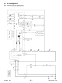
8. Schaltpläne
8.1 Stromlaufplan (Beispiel)
09.2002 R.K.
- 35 -
599 515 006
EN
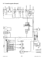
8.2 Verdrahtungsplan (Beispiel)
09.2002 R.K.
- 22 -
599 515 006
EN