1
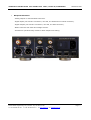
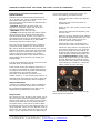
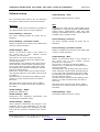
OPERATING INSTRUCTIONS FOR GAMBIT DAC2 24Bit / 192kHz D/A CONVERTER
INTRODUCTION
GAMBIT
DAC2
FIREWIRE DAC
OPERATING MANUAL
Issue: April 2010
Daniel Weiss Engineering Ltd., Florastr. 42, CH-8610 Uster
+41 44 940 20 06
+41 44 940 22 14
www.weiss.ch
Page 1
[email protected]
OPERATING INSTRUCTIONS FOR GAMBIT DAC2 24Bit / 192kHz D/A CONVERTER
INTRODUCTION
INTRODUCTION
Congratulations on purchasing the Weiss Gambit Series DAC2 D/A Converter !
The DAC2 is a stereo 24 bit / 192khz D/A converter which supports the following conversions:
-
Firewire to analog
-
AES/EBU to analog
-
Firewire to AES/EBU
-
AES/EBU to Firewire
Features
•
•
Inputs: There are two Firewire connectors and three AES/EBU (S/PDIF) inputs
on XLR, RCA and Toslink (optical) connectors. There are two Firewire connectors in order to be able to chain more
Firewire based units on a single Firewire
bus. Which of the two Firewire connectors is used for the connection to the
computer is not relevant. The accepted
sampling frequencies are 44.1, 48, 88.2,
96, 176.4 or 192 kHz.
An internal jumper allows to set the
XLR/RCA inputs to the dual wire
AES/EBU scheme in the case of 176.4 or
192kHz sampling rates.
Outputs: The analog cross-coupled type
balanced outputs can drive complex
loads without stability problems. The
output level is selectable from four different levels for both balanced and unbalanced outputs. The outputs are balanced on XLR connectors and unbalanced on RCA connectors.
In addition to the analog outputs there
are two digital outputs (AES/EBU on XLR
and RCA connectors) which allow to use
the DAC2 as an interface between computer and any other device which has
AES/EBU inputs.
An internal jumper allows to set the
XLR/RCA outputs to the dual wire
AES/EBU scheme in the case of 176.4 or
192kHz sampling rates.
Daniel Weiss Engineering Ltd., Florastr. 42, CH-8610 Uster
+41 44 940 20 06
+41 44 940 22 14
www.weiss.ch
•
Sampling Rates, Wordlength: 44.1,
48, 88.2, 96, 176.4, 192 kHz at up to 24
Bits.
•
Jitter suppression: Several signal reclocking schemes are combined for extremely high jitter attenuation, making
the DAC2 virtually immune to jitter over
a very wide bandwidth.
•
Converters: Eight times oversampling
sigma delta D/A converters are used.
•
Software: Drivers for Windows™ and
OSX™ operating systems.
•
Power Supply: A non-switching power
supply is used. All sensitive voltages
have their own local regulators. The
standby power supply leaves the Firewire chip powered. This allows to switch
on the DAC2 via the Firewire link. The
Firewire Bus Power is not used by the
DAC2, this allows the DAC2 to be used
with computers which do not supply Bus
Power. The mains voltage can be set to
100..120V or 200..240V.
•
Software features:
The software in the DAC2 allows for level
control (in the digital domain) and for an
insert mode which allows to insert any
external digital device in the signal path.
•
Frontpanel controls: Three switches
with corresponding LEDs are used for selecting one out of three input sources,
which are Firewire, AES/EBU, S/PDIF.
The S/PDIF selector selects both RCA
and Toslink inputs. One power switch.
Four LEDS for sampling rate indication.
Page 2
[email protected]
OPERATING INSTRUCTIONS FOR GAMBIT DAC2 24Bit / 192kHz D/A CONVERTER
•
INTRODUCTION
Backpanel Elements:
- Analog outputs on XLR and RCA connectors.
- Digital inputs (two Firewire connectors, one XLR, one RCA and one Toslink connector).
- Digital outputs (two Firewire connectors, one XLR, one RCA connector).
- Mains connector with fuses and voltage selector.
- Screwdriver operated rotary switch for basic output level setting.
Daniel Weiss Engineering Ltd., Florastr. 42, CH-8610 Uster
+41 44 940 20 06
+41 44 940 22 14
www.weiss.ch
Page 3
[email protected]
OPERATING INSTRUCTIONS FOR GAMBIT DAC2 24Bit / 192kHz D/A CONVERTER
OPERATION
OPERATION
Unpacking and Setup of the DAC2
Carefully unpack the DAC2. The following items
should be enclosed:
• The DAC2 D/A Converter unit
• A CD with the necessary Firewire drivers for
Windows and OSX
• This Owners Manual
Firewire Connection
Before connecting the Firewire cable between
computer and DAC2 unplug both the computer
and the DAC2 from the mains power.
Mains Connection
Before connecting the mains cable make sure
the voltage selector switch on the back of the
unit
(integrated into the mains connector) is set to
the appropriate voltage. If this is not the case
then
open the mains selector lid with a strong screwdriver. The mains plug must not be plugged into
the connector for that purpose. Now you see a
black selector drum with appropriate voltages
written in white letters. Remove this drum, turn
it to the appropriate voltage and reinsert it. Now
firmly close the lid again. Connect the DAC2 to
the wall outlet with the mains cable.
Operation Modes
The DAC2 operates in various modes. The power
switch, the Firewire switch and the S/PDIF
switch are used to toggle between these modes.
If the power switch is held pressed for longer
than 1.5 seconds, the mode of the DAC2 is toggled between “input selection” and “volume control” modes. If the Firewire switch or the S/PDIF
switch is held pressed for longer than 1.5 seconds, the mode of the DAC2 is toggled between
“normal signal path” and “insert signal path”.
Explanation of these modes follow below:
the “volume down” control, the “FIREWIRE”
switch becomes the “dim” control. The dim
switch lowers the volume by 20dB. When
dimmed, the Firewire switch is flashing. The up /
down switches step the volume up / down by
0.5dB steps over a 120 dB range. If the up or
down switch is held pressed, the volume
changes continuously. The volume control is
done in the digital domain and is properly dithered, which means that the quality of the level
control is at least on par with an analog volume
control. Ideally the DAC2 unit is operated at
digital volume levels at or near to the maximum
level in order to utilize the dynamic range of the
DAC2. The basic analog output level can be set
as described below.
Toggle with FIREWIRE or S/PDIF switch
(press switch longer than 1.5 seconds):
- “normal signal path” mode: In this mode the
DAC2 accepts signals from the selected input,
i.e. From Firewire, XLR, RCA, Toslink inputs.
- “insert signal path” mode: In this mode an external digital audio device (e.g. a digital equalizer) can be looped into the signal path via the
XLR input / output connectors. The resulting
signal path thus looks as follows: Firewire (or
RCA or Toslink) input XLR output external
device XLR input DAC chip. The “insert signal path” mode is indicated as follows: If the
Firewire is the main input, the Firewire and
AES/EBU switches are lit. If the S/PDIF is the
main input the S/PDIF and AES/EBU switches
are lit. So to enable the insert mode when the
Firewire input is selected press the FIREWIRE
switch for longer than 1.5 seconds. To enable
the insert mode when the S/PDIF input is selected press the S/PDIF switch for longer than
1.5 seconds. To leave the insert mode again
press the FIREWIRE (or S/PDIF switch if appropriate) for longer than 1.5 seconds.
Toggle with power switch (press switch
longer than 1.5 seconds):
- “input selection” mode: In this mode the input
source can be selected with the three switches
to the right of the power switch.
- “volume control” mode: Both AES/EBU and
S/PDIF switches are lit to indicate that mode. In
this mode the “S/PDIF” switch becomes the
“volume up” control, the “AES/EBU” switch becomes
Daniel Weiss Engineering Ltd., Florastr. 42, CH-8610 Uster
+41 44 940 20 06
+41 44 940 22 14
www.weiss.ch
Page 4
[email protected]
OPERATING INSTRUCTIONS FOR GAMBIT DAC2 24Bit / 192kHz D/A CONVERTER
Input Source Connection, Selection and
Synchronization
Connect sources with sampling frequencies of
44.1, 48, 88.2, 96, 176.4 or 192kHz to the input
connectors at the back of the unit.
The input source pushbuttons correspond to the
inputs as follows:
- Firewire: Selects the Firewire input, connected to a computer. Either one of the two
Firewire connectors can be used.
- AES/EBU: Selects the XLR input.
- S/PDIF: Selects both RCA and Toslink inputs.
At the first hit of the S/PDIF switch the DAC2
selects the RCA input. If there is no signal recognized at the RCA input it automatically selects
the Toslink input. A second hit on the S/PDIF
switch also selects to Toslink input.
OPERATION
els is repeated when rotating the switch. For
proper level setting proceed as follows:
-
Power up the DAC2, select the appropriate input.
-
Select the level control mode as described above.
-
Switch on the “dim” mode ( Firewire LED
flashing).
-
Connect the DAC2 to the amplifier, play
a music track.
-
-
The sync sources correspond to the respective
input sources per default. The “Weiss Firewire
IO” control panel allows alternative sync source
selection in Firewire input mode. As long as the
DAC2 is connected via Firewire, these sync settings are stored for persistent sync settings
when switching between input modes. As soon
as the DAC2 is disconnected, the default sync
settings apply.
If a valid synchronization signal is present at the
selected input, the LED stays lit.
With the currently selected level settings
the music should be fairly soft. If it is already fairly loud, make sure to turn
down the gain at the amplifier.
Switch off the “dim” mode and make
sure that the volume at the DAC2 is at
maximum. If the music is now playing at
the proper loudness then you are done.
If the music is still too soft (with an appropriate gain setting at your amplifier)
rotate the gain switch shown below one
step counterclockwise. Rotate more
steps if the music is still too soft. There
are four different level settings selectable with the rotary switch. The settings
repeat when you continue to rotate the
switch. There isn’t any end stop.
If the format and/or the sampling frequency is
not valid, the LED flashes. In that case the analog outputs are muted. The DAC2 automatically
synchronizes to the incoming signal.
The states of all buttons are stored in nonvolatile memory, i.e. the actual input selection is
retained when powering the unit off or when disconnecting the unit from the mains completely.
Output Connection
Connect your preamplifier or power amplifier to
the output connectors of the DAC2. Use either
the symmetrical (balanced) lines (XLR) or the
asymmetrical (unbalanced) lines (RCA).
Output Level
The output level can be set by two means, one is
the level control mode described above (digital
domain level control), the other is via the rotary
switch on the back of the unit (analog domain,
see photo below). This switch is used to adapt
the DAC2’s output level to the subsequent pre- or
power amplifier. There are four different levels to
chose from. The rotary switch does not have end
stops, i.e. the sequence of the four different lev-
White arrow points to the rotary switch for the
basic output level selection.
Daniel Weiss Engineering Ltd., Florastr. 42, CH-8610 Uster
+41 44 940 20 06
+41 44 940 22 14
www.weiss.ch
Page 5
[email protected]
OPERATING INSTRUCTIONS FOR GAMBIT DAC2 24Bit / 192kHz D/A CONVERTER
OPERATION
Dual Wire / Single Wire
Factory setting is on single wire as shown below:
For dual wire format remove the 1st jumper:
In dual wire format the XLR connectors are
channel 1 input or output respectively and the
RCA connectors are channel 2 input or output
respectively. Inputs / outputs can not be set individually to dual wire mode. Dual wire mode is
active at 176.4 or 192kHz only.
-
a volume control not at 0dB gain
an equalizer
a sampling rate conversion
a “sound enhancer” feature and more
Make sure all these processing elements are bypassed. Particularly the sampling rate conversion can creep in “unnoticed”. I.e. the measured
sampling rate in the “Weiss Firewire IO” window
has to match the sampling rate of the file
played, else a conversion is going on in the operating system. For iTunes there is another thing
to know: Whenever the sampling rate is changed
in the AudioMidi setup or the “Weiss Firewire IO”
window, the iTunes program has to be restarted
to gain bit transparency again. For iTunes running on a Mac computer a program like Sonic
Studio’s “Amarra” is highly recommended. With
Amarra it is possible to switch the sampling rate
in Audio- Midi (i.e. in the DAC2) automatically
depending on the sampling rate of the file
played. Amarra works in conjunction with
iTunes.
On a Windows based system the use of ASIO or
WASAPI is highly recommended. These systems
make it simple to achieve bit transparent playback. In addition the sampling rate of the DAC2
is switched automatically depending on the
sampling rate of the file played. Note that the
test audio files do not generate any audible audio signal. This makes sure that your speakers
are protected when doing the test.
Bit Transparency Check
The DAC2 allows to check the player software
running on the computer for bit transparency.
This is done by playing a test audio file on the
computer. The DAC2 then checks whether it receives the special bit pattern from the test file.
This check is running in the background of the
DAC2 software, i.e. as soon as the DAC2 detects
such bit patterns it flashes three of the LEDs on
the frontpanel. I.e. the flashing LEDs indicate
that the player is indeed bit transparent.
There are a total of 12 files for bit transparency
check, one for each sampling rate (44.1, 48,
88.2, 96, 176.4, 192 kHz) and for 16 and 24 bit
wordlengths. We suggest to start with testing
the 24 bit wordlength. The files are in WAV format which is an uncompressed format supported
by most players. They can be downloaded from
our website as indicated below under “Firmware
/ Drivers”.
If the player does not seem to be bit transparent
this can have several reasons, such as:
Daniel Weiss Engineering Ltd., Florastr. 42, CH-8610 Uster
+41 44 940 20 06
+41 44 940 22 14
www.weiss.ch
Page 6
[email protected]
OPERATING INSTRUCTIONS FOR GAMBIT DAC2 24Bit / 192kHz D/A CONVERTER
Software installation
Perform the following installation procedure before connecting the DAC2 to the computer. The
necessary files are supplied on the enclosed
drivers CD.
Windows:
0. Do not connect the device.
OPERATION
After installing the drivers, connect the DAC2 to
the computer and connect the power cord to the
DAC2.
The DAC2 should now be recognized automatically. In Windows tell the installation window
that you do not want to check the Microsoft
website for drivers and then let the drivers be
installed automatically. Ignore warnings concerning “Windows Logo Test” and continue the
installation until completed. There will be two
passes of installation, which is normal.
1. Double click "WeissFirewireInstaller.exe"
2. Click "Next"
3. Select the directory where you'd like to install
the tools. Usually you can use the default values
and click "Next"
4. Select if you'd like to create a desktop icon.
"Next"
5. Click "Install"
6. You will be asked if you'd like to continue the
installation because the driver/software didn't
pass the Windows-Logo-Test. Select "Continue".
7. Select "Yes, restart the computer now" and
click "Finish"
Mac:
0. Mount the WeissFirewire.dmg diskimage by
double clicking it
1. From the mounted drive double click WeissFirewire-3.3.1.2228.pkg (the version numbers
can be different of course)
2. Click "Continue"
3. Select the drive (usually you leave it at the
defaults)
4. Click "Continue"
5. Click "Upgrade" or "Install"
6. You'll be asked to login as administrator
7. Confirm "Continue Installation" when warned
that the computer requires a reboot after install.
8. Click Restart
Daniel Weiss Engineering Ltd., Florastr. 42, CH-8610 Uster
+41 44 940 20 06
+41 44 940 22 14
www.weiss.ch
Page 7
[email protected]
OPERATING INSTRUCTIONS FOR GAMBIT DAC2 24Bit / 192kHz D/A CONVERTER
Software setup
OPERATION
Global Settings / Info:
Information about the driver version.
The connected DAC2 device can be controlled
through the “Weiss Firewire I/O” Control Panel.
Windows:
Mac:
The control panel can be accessed by clicking on
the “Weiss Firewire IO” icon on the desktop.
Configure the DAC2 via the “Audio MIDI Setup”
(Applications > Utilities) and the “WeissFirewire
Control Panel” (Applications). Note that most
settings controllable from the control panel are
available only in Firewire mode.
Device Settings / General:
The device settings should be pretty self explanatory.
Device Settings / Firmware Loader:
Allows to upload new firmware to the DAC2. Not
used for normal operation.
Device Settings / General:
The device settings should be pretty self explanatory.
Device Settings / Firmware Loader:
Global Settings / Bus:
Master: Is the device which is sync master on
the virtual bus in case multiple devices
(“DAC2s”) are connected.
Sync Source: The clock to which the DAC2
should sync to. Usually this is the DAC2’s internal clock generator.
Sampling Rate: The sampling rate of the device
when internally clocked. When clocked/syncing
to one of the other interfaces (XLR, RCA, TOS)
the sampling rate indicated reflects the one fed
from the external device.
Buffer Size: Larger buffer sizes increase robustness against dropouts, lower buffer sizes provide
low latency.
Operation Mode: determines the stability of the
system. Try other modes if there are clicks in
the music.
Note that when using the XLR, RCA or TOS inputs there is no need to hook up a computer to
the DAC2.
Allows to upload new firmware to the DAC2. Not
used for normal operation.
Global Settings / Bus:
Master: Is the device which is sync master on
the virtual bus in case multiple devices
(“DAC2s”) are connected.
Sync Source: The clock to which the DAC2
should sync to. Usually this is the DAC2’s internal clock generator.
Sampling Rate: The sampling rate of the device
when internally clocked. When clocked/syncing
to one of the other interfaces (XLR, RCA, TOS)
the sampling rate indicated reflects the one fed
from the external device.
Operation Mode: determines the stability of the
system. Try other modes if there are clicks in
the music.
Note that when using the XLR, RCA or TOS inputs there is no need to hook up a computer to
the DAC2.
Global Settings / WDM:
Enables the WDM driver.
Global Settings / DPC:
Global Settings / Info:
Information about the driver version.
Determines your computers performance and
recommends a operation mode.
Global Settings / System:
Some utilities to determine the chipset in your
computer and to get information on the supported chipset. Required for debugging if problems with the Firewire connection are encountered.
Daniel Weiss Engineering Ltd., Florastr. 42, CH-8610 Uster
+41 44 940 20 06
+41 44 940 22 14
www.weiss.ch
Page 8
[email protected]
OPERATING INSTRUCTIONS FOR GAMBIT DAC2 24Bit / 192kHz D/A CONVERTER
OPERATION
Firmware / Drivers
Latest download links:
(login: weissuser, password: saracon0505)
−
Weiss Firewire IO drivers & control panel:
− Windows (XP, Vista, 7):
http://www.weiss.ch/downloads/firewire
/win32/WeissFirewireInstaller.exe
−
MAC:
http://www.weiss.ch/downloads/firewire
/osx/WeissFirewire.dmg
−
DAC2 / Minerva Firmware:
http://www.weiss.ch/downloads/dac2fw/min
erva_tcd22x0Debug.bin
−
Bit Transparency Check:
− WAV files:
http://www.weiss.ch/downloads/dac202f
w/dac202-trnz-wav.zip
− FLAC files:
http://www.weiss.ch/downloads/dac202f
w/dac202-trnz-flac.zip
Daniel Weiss Engineering Ltd., Florastr. 42, CH-8610 Uster
+41 44 940 20 06
+41 44 940 22 14
www.weiss.ch
Page 9
[email protected]
OPERATING INSTRUCTIONS FOR GAMBIT DAC2 24Bit / 192kHz D/A CONVERTER
TECHNICAL DATA
TECHNICAL DATA
Digital Inputs:
- (1) XLR connector, (1) RCA connector, (1) Toslink connector (optical), (2) Firewire connectors.
- All inputs accept professional or consumer standard , i.e. accept AES/EBU or S/PDIF signals.
- Sampling Frequencies: 44.1, 48.0, 88.2, 96.0, 176.4 or 192kHz on any of the inputs.
- Maximum input wordlength: 24 Bits.
- Dual wire mode (internal jumper): channel 1 on XLR, channel 2 on RCA input, active at 176.4 or 192
only.
Digital Outputs:
- (1) XLR connector, (1) RCA connector, (2) Firewire connectors.
- Professional Channel Status Data on the XLR and RCA outputs.
- Dual wire mode (internal jumper): channel 1 on XLR, channel 2 on RCA output, active at 176.4 or 192
only.
Analog Outputs:
(2) XLR Connectors (hot output on pin 2, servo controlled), (2) RCA Connectors
DC coupled, short circuit proofed output circuitry, Output impedance: 50 Ohm
Output level: Selectable by a rotary switch on the back, 4 settings, same level at both RCA and XLR outputs:
+17 dBu (5.48Vrms) with a 0dBFS sinewave input
+11 dBu (2.74Vrms) with a 0dBFS sinewave input
+7.2 dBu (1.78Vrms) with a 0dBFS sinewave input
+4.8 dBu (1.35Vrms) with a 0dBFS sinewave input
Synchronization:
- Synchronized via input signal.
- Extremely efficient Jitter attenuation down to subsonic frequencies.
- Sampling Frequencies: 44.1 kHz, 48.0 kHz, 88.2kHz, 96.0kHz, 176.4khz, 192kHz
Power:
- Mains Voltage: 100...120 / 200...240 Volt
- Fuse rating: 500 mA slow blow at 100…120V, 250mA slow blow at 200…240V
- Power consumption: 7VA max.
- Power consumption in standby: 3VA max.
Measurements:
The measurements below have been taken at the following conditions (unless noted otherwise):
1kHz measurement frequency, +17.0 dBu (equals 0dBr ) output level, 48.0kHz sampling frequency (f ),
s
22kHz measurement bandwidth.
Frequency Response: 0Hz ... 20kHz: within +- 0.3dB
Total Harmonic Distortion plus Noise (THD+N): < -100 dBr (0.001 %) @ -3 dBFS input level
Linearity: at 0 to -120dBFS input level: less than +-1dB deviation from ideal
Noise floor @ -20dBFS input: < -107dBr unweighted
Crosstalk: < -110dB, 0..20kHz
Interchannel Phase Response: < +- 0.5°, 10Hz ... 20kHz
Daniel Weiss Engineering Ltd., Florastr. 42, CH-8610 Uster
+41 44 940 20 06
+41 44 940 22 14
www.weiss.ch
Page 10
[email protected]