1
."
.
~
-(iltlJ
.
.....
~
"
~
1
If'
"-o
.
~ ~.
q
'"
p "". '
O'PERATORS MANUAL
1
MARINE DI"ESEL ENGINES
!5~58-fOU~ . • 55C-fQuiji I .
-
- -
,'and 550· OUR -'-
.
PUBLICATION NO.42286
REVISION 4
JULY 2011
..
,~
-member
J3tJiJ'
.
-
-
,
WESTERBEKE
WESTERBEKECORPORATION.150JOHNHANCOCKROAD
MYLES STANDISH INDUSTRIAL PARK· TAUNTON MA 02780
WEBSITE: www.WESTERBEKECOM
·'''''i. 0-
~
!
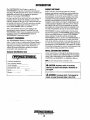
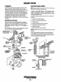
CALIFORNIA PROPOSITION 65
WARNING
Exhaust gas from diesel and
gasoline engines (and some of
its constituents) are known to
the State of California to cause
cancer, birth defects, and other
reproductive harm.
A WARNING:
Exhaust gasses contain Carbon Monoxide, an odorless and
colorless gas. Carbon Monoxide is poisonous and can cause
unconsciousness and death. Symptoms of Carbon Monoxide
exposure can include:
-Dizziness
- Throbbing in Temples
-Nausea.
- Muscular Twitching
-Headache
- Vomiting
- Weakness andSleepiness -Inability to Think Coherently
IF YOU OR ANYONE ELSE EXPERIENCE ANY OF THESE SYMPTOMS,
GET OUT INTO THE FRESH AIR IMMEDIATELY. If symptoms persist,
seek medical attention. Shut down the unit and do not restart
until It has been inspected and repaired.
A WARNING DECAL is provided by WESTERBEKE and
should be fixed to a bulkhead near your engine or
generator.
WESTERBEKE also recommends installing CARBON
MONOXIDE DETECTORS in the living/sleeping quarters
of your vessel. They are inexpensive and easily
obtainable at your local marine store.
WARNING
Gooem\ors PIrXIuce CARBON MClNOXIDE
Regular MailIenance ReqoJrecI
~
Engines & Generators
SAFETY INSTRUCTIONS
PREVENT BURNS - FIRE
INTRODUCTION
Read this safety manual carefully. Most accidents are
caused by failure to fol1ow fundamental rules and precautions. Know when dangerous conditions exist and take the
necessary precautions to protect yourself, your personnel,
and your machinery.
The following safety instructions are in compliance with
the American Boat and Yacht Council (ABYC) standards.
A WARNING: Fire can cause injury Dr death!
• Prevent flash fires. Do not smoke or permit flames or
sparks to occur near the carburetor, fuel line, filter, fuel
pump, or other potential sources of spilled fuel or fuel
vapors. Use a suitable container to catch all fuel when
removing the fuel line, carburetor, or fuel filters.
• Do not operate with a Coast Guard Approved flame
arrester removed. Backfire can cause severe injury or
death.
• Do not operate with the air cleaner/silencer removed.
Backfire can cause severe injury or death.
• Do not smoke or permit flames or sparks to occur near
the fuel system. Keep the compartment and the
engine/generator clean and free of debris to minllnize the
chances of fire. Wipe up all spilled fuel and engine oil.
• Be aware - diesel fuel will bum.
PREVENT ELECTRIC SHOCK
A WARNING: Do not touch AC electrical connections
while engine is running, Dr when connected to shore
power. Lethal voltage is present at these connections!
•
•
•
•
•
•
•
Do not operate this machinery without electrical
enclosures and covers in place.
Shut off electrical power before accessing electrical
equipment.
Use insulated mats whenever working on electrical
equipment.
Make sure your clothing and skin are dry, not damp
(particularly shoes) when handling electrical equipment.
Remove wristwatch and all jewelry when working on
electrical equipment.
Do not connect utility shore power to vessel's AC
circuits, except through a ship-to-shore double throw
transfer switch. Damage to vessel's AC generator may
result if this procedure is not followed.
Electrical shock results from handling a charged capacitor. Discharge capacitor by shorting terminals together.
PREVENT BURNS - EXPLOSION
A WARNING: Explosions from fuel vapors can cause
injury Dr death!
• Follow re-fueliug safety instructions. Keep the vessel's
hatches closed when fueling. Open and ventilate cabin
after fueling. Check below for fumes/vapor before running the blower. Run the blower for four minutes before
starting your engine.
• All fuel vapors are highly explosive. Use extreme care
when handling and storing fuels. Store fuel in a well-ventilated area away from spark-producing equipment and
out of the reach of children.
• Do not fill the fuel tank(s) while the engine is running.
• Shut off the fuel service valve at the engine when servicing
the fuel system. Take care in catching any fuel that might
spill. DO NOT allow any smoking, open flames, or other
sources of fire near the fuel system or engine when servicing. Ensure proper ventilation exists when servicing the
fuel system.
• Do not alter or modify the fuel system.
• Be sure all fuel supplies have a positive shutoff valve.
• Be certain fuelliue fittings are adequately tightened and
free ofleaks.
• Make sure a fire extinguisher is installed nearby and is
properly maintained. Be fantiliar with its proper use.
Extinguishers rated ABC by the NFPA are appropriate
for all applications encountered in this environment.
PREVENT BURNS - HOT ENGINE
A WARNING: Do not touch hot engine parts Dr
exhaust system components. Arunning engine gets
very hot!
• Always check the engine coolant level at the coolant
recovery tank.
A WARNING: Steam can cause injury Dr death!
•
In case of an engine overheat, allow the engine to cool
before touching the engine or checking the coolant.
Engines & Generators
i
SAFETY INSTRUCTIONS
TOXIC EXHAUST GASES
ACCIDENTAL STARTING
A WARNING: Accidental starting can cause injury
A WARNING: Carlion monoxide (CO) is a deadly gas!
or death!
•
• Ensure that the exhaust system is adequate to expel gases
discharged from the engine. Check the exhaust system
regularly for leaks and make sure the exhaust manifolds
are securely attached and no warping exists. Pay close
attention to the manifold, water injection elbow, and
exhaust pipe nipple.
• Be sure the unit and its surroundings are well ventilated.
• In addition to routine inspection of the exhaust system,
install a carbon monoxide detector. Consult your boat
builder or dealer for installation of approved detectors.
• For additional information refer to ABYC T-22 (educational information on Carbon Monoxide).
Disconnect the battery cables before servicing the engine!
generator. Remove the negative lead first and reconnect
it last.
Make certain all personnel are clear of the engine before
starting.
Make certain all covers, guards, and hatches are reinstalled before starting the engine.
•
•
BAnERY EXPLOSION
A WARNING: Batteryexplosion can cause injury
or death!
A WARNING: Carbon monoxide (CO) is an inviSible
•
Do not smoke or allow an open flame near the battery
being serviced. Lead acid batteries emit hydrogen, a
highly explosive gas, which can be ignited by electrical
arcing or by lit tobacco products. Shut off all electrical
equipment in the vicinity to prevent electrical arcing during servicing.
• Never connect the negative (-) battery cable to the positive (+) connection terminal of the starter solenoid. Do
not test the battery condition by shorting the terminals
together. Sparks could ignite battery gases or fuel vapors.
Ventilate any compartment containing batteries to prevent
accmnulation of explosive gases. To avoid sparks, do not
disturb the battery charger connections while the battery
is being charged.
• Avoid contacting the terminals with tools, etc., to prevent
bums or sparks that could cause an explosion. Remove
wristwatch, rings, and any other jewelry before handling
the battery.
• Always tum the battery charger off before disconnecting
the battery connections. Remove the negative lead first
and reconnect it last when disconnecting the battery.
odorless gas. Inhalation produces flu-like symptoms,
nausea or death!
• Do not use copper tubing in diesel exhaust systems. Diesel
fumes can rapidly destroy copper tubing in exhaust systems. Exhaust sulfur causes rapid deterioration of copper
tubing resulting in exhauslfwater leakage.
• Do not install exhaust outlet where exhaust can be drawn
through portholes, vents, or air conditioners. If the engine
exhaust discharge outlet is near the waterline, water could
enter the exhaust discharge outlet and close or restrict the
flow of exhaust. Avoid overloading the craft.
• Although diesel engine exhaust gases are not as toxic as
exhaust fumes from gasoline engines, carbon monoxide
gas is present in diesel exhaust fumes. Some of the symptoms or signs of carbon monoxide inhalation or poisoning
are:
Vomiting
Dizziness
Throbbing in temples
BAnERYACID
AVOID MOVING PARTS
A WARNING: Sulfuric acid in batteries can cause
A WARNING: Rotating parts can cause injury
severe injury or death!
•
Muscular twitching
Intense headache
Weakness and sleepiness
or death!
When servicing the battery or checking the electrolyte
level, wear rubber gloves, a rubber apron, and eye protection. Batteries contain sulfuric acid which is destructive.
If it comes in contact with your skin, wash it off at once
with water. Acid may splash on the skin or into the eyes
inadvertently when removing electrolyte caps.
•
Do not service the engine while it is running. If a situation arises in which it is absolutely necessary to make
operating adjustments, use extreme care to avoid touching moving parts and hot exhaust system components.
Engines & Generators
ii
SAFETY INSTRUCTIONS
•
Do not wear loose clothing or jewelry when servicing
equipment; tie back long hair and avoid wearing loose
jackets, shirts, sleeves, rings, necklaces or bracelets tltat
could be caught in moving parts.
• Make sure all attaching hardware is properly tightened.
Keep protective shields and guards in tlteir respective
places at all times.
• Do not check fluid levels or tlte drive belt's tension while
tlte engine is operating.
• Stay clear of tlte drive shaft and tlte transmission coupling
when tlte engine is running; hair and clothing can easily
be caught in tltese rotating parts.
HAZARDOUS NOISE
A WARNING: High noise levels can cause hearing
loss!
•
•
Never operate an engine witltout its muffler installed.
Do not run an engine witlt tlte air intake (silencer)
removed.
• Do not run engines for long periods witlt tlteir enclosures
open.
A WARNING: 00 not work on machinery when you are
ABYC, NFPA AND USCG PUBLICATIONS FOR
INSTALLING DIESEL ENGINES
Read tlte following ABYC, NFPA and USCG publications
for safety codes and standards. Follow tlteir recommendations when installing your engine.
ABYC (American Boat and Yacht Council)
"Safety Standards for Small Craft"
Order from:
ABYC
3069 Solomon's Island Rd.
Edgewater, MD 21037
NFPA (National Fire Protection Association)
"Fire Protection Standard for Motor Craft"
Order from:
NFPA
11 Tracy Drive
Avon Industrial Park
Avon, MA 02322
USCG (United States Coast Guard)
"USCG 33CFR183"
Order from:
U.S. Government Printing Office
Washington, D.C. 20404
mentally or physically incapacitated by fatigue!
OPERATORS MANUAL
Many of tlte preceding safety tips and warnings are repeated
in your Operators Manual along witlt otlter cautions and
notes to highlight critical information. Read your manual
carefully, maintain your equipment, and follow all safety
procedures.
GASOLINE ENGINE AND GENERATOR INSTALLATIONS
Preparations to install a gasoline engine or generator should
begin witlt a tltorough exantiuation of tlte American Boat and
Yacht Council's (ABYC) standards. These standards are from
a combination of sources including 1he USCG and tlte NFPA.
Sections of tlte ABYC standards of particular interest are:
H-2 Ventilation
H-24 Gasoliue Fuel Systems
P-l Exhaust Systems
P-4 Inboard Engines
E-9 DC Electrical Systems
All installations must comply witlt tlte Federal Code of
Regulations (FCR).
" . WESTERBEKE
Engines & Generators
iii
INSTALLATION
When installing WESTERBEKE engines and generators it is important that strict
attention be paid to the following information:
CODES AND REGULATIONS
Strict federal regulations, ABYC guidelines, and safety codes must be complied with
when installing engines and generators in a marine environment.
SIPHON·BREAK
For installations where the exhaust manifold/water injected exhaust elbow is close to
or will be below the vessel's waterline, provisions must be made to install a siphonbreak in the raw water supply hose to the exhaust elbow. This hose must be looped a
minimum of 20" above the vessel's waterline. Failure to use a siphon-break when
the exhaust manifold injection port is at or belbw the Ibad waterline will result in
raw water damage to the engine and possible flooding of the boat.
If you have any doubt about the position of the water-injected exhaust elbow relative
to the vessel's waterline under the vessel's valious operating conditions, install a
siphon-break.
NOTE: A siphon-break requires periodic inspection and cleaning to ensure proper
operation. Failure to properly maintain a siphon-break can result in catastrophic
engine damage. Consult the Siphon-break manufacturer for proper maintenance.
EXHAUST SYSTEM
The exhaust hose must be certified for maline use. The system must be desigued to
prevent water from entering the exhaust under any sea conditions and at any angle
of the vessels hull.
Adetailed Marine Installation Manual covering gaSOline and diesel,
engines and generators, is supplied with each unit. A pdf is available
to download from our website at www.westerbeke.com.
-."y:
WESTERBEKE
Engines & Generators
iv
TABLE OF CONTENTS
Parts Identification ................................................2
Introduction .............................................................3
Warranty Procedures ......................................... 3
Serial Number Location .................................. .4
Siphon Break .................................................... 4
Remote Oil Filter (Optional) ..............................21
Water Heater .....................................................22
Tachometer ........................................................23
DC Electrical System .........~.................................24
Alternator Troubleshooting ............................ 24
Battery Care .................................................... 25
Glow Plugs .........................................................26
Admiral Control Panel .........................................5
Captain Control Panel .........................................6
Fuel, Engine Oil and Coolant.. ............................7
Preparations for Initial Start-Up .........................8
Starting/Stopping Procedure ...............................9
Warning Lights, Alarms and Circuit Breaker .... 10
Engine Break-In Procedure ............................... 11
The Daily Operation ...........................................12
Maintenance Schedule .................................... .13
Fuel System ....................................................... 15
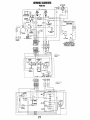
Wiring Diagram ..................................................27
Wiring Schematic ..............................................28
Starter Motor .....................................................29
Dual Output Alternators ....................................31
Troubleshooting .............................................. 32
Engine Troubleshooting .................................... .33
Engine Adjustments .............................................35
Belt Adjustments ........................................... .35
Fuel Injectors ................................................ .35
Testing Engine Compression .......................... 36
Oil Pressure ....... : ............................................36
Valve Clearance Adjustment .......................... 37
Hurth HSW Transmissions ................................ .3 8
Transmission Coolers ................................... .40
Maintenance ................................................... .40
Troubleshooting ............................................. .41
FuellWater Separator ...................................... 15
Fuel Filters ...................................................... 15
COOling System .................................................. 16
Changing Coolant ........................................... 16
Thermostat ...................................................... 17
Raw Water Intake Strainer.............................. 17
Raw Water Cooling Circuit ............................ 18
Heat Exchanger .............................................. 18
Raw Water Pump ............................................ 18
Zinc Anode ..................................................... 19
Air Intake/Silencer.......................................... 19
Engine Lubricating System ...............................20
Changing the Oil Filter ................................... 20
Changing the Oil ............................................ 20
Borg Warner Transmission ................................43
Maintenance .................................................... 45
Oil Coolers ...................................................... 45
Lay-up and Recommissioning .......................... .46
Metric Conversions Oata ...................................48
Engine Specifications .......................................49
Suggested Spare Parts ......................................50
Engines & Generators
1
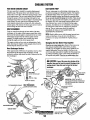
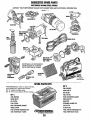
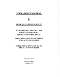
PARTS IDENTIFICATION
Oil FIll
PUUILAW I
INTAKE/AIR FILTER
PRESSURE CAP
THERMOSTAT
ASSEMBLY
WATER INJECTED
EXHAUST ELBOW
I.D. PLATE
~_'r--lltAI
EXCHANGER
WATER
REAR
ANDDE
RAW WATER om,," ___
FRONT
LEFT SIDE
DC AlTERNA1'OR ( "'"'~~
WATER INJECTED
EXHAUST
PREHEAT ~Ul.<Nl"U,
AIR INTAKE/AIR
FIll
THERMOSTAT
. FUEL LIFT PUMP
20A CIRCUIT
BREAKER
REAR
___ ,.,,,,,n HEATER
CONNECTION
FUEL FILTER ----:-~~
HEAT EXCHANGER
-------;>
~--U"
ALTERNATOR
FRONT'
CRANKSHAFT
PULLEY
SHIFT LEVER
Oil FIll
OIL COOLER
OIL PRESSUIRE
SENDOR
MOUNT
RIGHT SIDE
Engines & Generators
2
INTRODUCTION
This WESTERBEKE Diesel Engine is a product of
WESTERBEKE's long years of experience and advanced
technology. We take great pride in the superior durability and
dependable performance of our engines and generators.
Thank you for selecting WESTERBEKE.
In order to get the full use and benefit from your engine, it is
important that you operate and maintain it correctly. This
manual is designed to help you do this. Please read this manual carefully and observe all the safety precautions through- .
out. Should your engine require servicing, contact your
nearest WESTERBEKE dealer for assistance.
This is your operators manual. A parts catalog is also
provided and a technical manual is available from your
WESTERBEKE dealer. If you are planning to install this
equipment, contact your WESTERBEKE dealer for
WESTERBEKE'S installation manual.
PRODUCT SOFTWARE
Product software, (technical data, parts lists, manuals,
brochures and catalogs), provided from sources other than
WESTERBEKE are not within WESTERBEKE's control.
WESTERBEKE CANNOT BE RESPONSIBLE FOR THE
CONTENT OF SUCH SOFTWARE, MAKES NO WARRANTIES OR REPRESENTATIONS WITH RESPECT
THERETO, INCLUDING ACCURACY, TIMEUNESS OR
COMPLETENESS THEREOF AND WILL IN NO EVENT
BE UABLE FOR ANY TYPE OF DAMAGE OR INJURY
INCURRED IN CONNECTION WITH OR ARISING OUT
OF THE FURNISHING OR USE OF SUCH SOFTWARE.
WESTERBEKE customers should keep in mind the time
span between printings of WESTERBEKE product software
and the unavoidable existence of earlier WESTERBEKE
product software. The product software provided with
WESTERBEKE products, whether from WESTERBEKE or
other suppliers, must not and cannot be relied upon exclusively as the definitive authority on the respective product. It
not only makes good sense but is imperative that appropriate
representatives of WESTERBEKE or the supplier in question
be consulted to determine the accuracy and currentness of the
product software being consulted by the customer.
WARRANTY PROCEDURES
Your WESTERBEKE Warranty is included in a separate
folder. If, after 60 days of submitting the Warranty Registry
form you have not received a customer identification card
registering your warranty, please contact the factory in
writing with model infonnation, including the engine's
serial number and commission date.
NOTES, CAUTIONS AND WARNINGS
Customer Identification Card
As this manual takes you through the operating procedures,
maintenance schedules, and troubleshooting of your marine
engine, critical infonnation will be highlighted by NOTES,
CAUTIONS, and WARNINGS. An explanation follows:
'~jWESTERBEKE
_ f
.
NOTE: An operating procedure essential to note.
Customer Identification
MR. ENGINE OWNER _ __
MAIN STREET _ _ _ _ __
HOMETOWN, USA _ _ _ __
Ser. #._____
Model _ _ _ __
I
•
Exprres _ _ _ __
A CAUTION: Procedures which, if not strictly
observed, can result in the damage or destruction of
your engine.
A WARNING: Procedures which, if not properly fol·
lowed, can result in personal injury or loss of life.
Engines & Generators
3
INTRODUCTION
SERIAL NUMBER LOCATION
ORDERING PARTS
The engine's model number and serial number are located on
a nameplate mounted on the side of the engine's manifold.
The engine's serial number can also be found stamped into
the engine block on the flat surface of the block just forward
of the number one cylinders injection pump. Take the time to
enter this information on the illustration of the nameplate
shown below, as this will provide a quick reference when
seeking techuical information and/or ordering repair parts.
Whenever replacement parts are needed, always provide the
engine model number and serial number as they appear on
the silver and black nameplate located on the manifold. You
must provide us with this information so we may properly
identify your engine. In addition, include a complete part
description and part number for each part needed (see the
separately furnished Parts List). Insist upon WESTERBEKE
packaged parts because will fit or generic parts are frequently
not made to the same specifications as original equipment.
SPARES AND ACCESSORIES
Certain spares will be needed to support and maintain your
WESTERBEKE engine. Your local WESTERBEKE dealer
will assist you in preparing an inventory of spare parts.
See the SPARE PARTS page in this manual. For engine
accessories, see WESTERBEKE'S ACCESSORIES brochure.
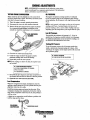
UNDERSTANDING THE DIESEL ENGINE
RAW WATER COOLING SYSTEM
The diesel engine closely resembles the gasoline engine,
since the mechanism is essentially the same. The cylinders
are arranged above a closed crankcase. The crankshaft is the
same general type as a gasoline engine, and the diesel engine
has the same type of valves, camshaft, pistons, connecting
rods and lubricating system.
Therefore, to a great extent, a diesel engine requires the same
preventive maintenance as a gasoline engine. The most
important factors are proper ventilation and proper maintenance of the fuel, lubricating and cooling systems. Fuel and
lubricating filter elements must be replaced at the time
periods specified, and frequent checking for contaminant's
(water, sediment, etc.) in the fuel system is also essential.
Another important factor is the consistent use of the same
brand of high detergent diesel lubrication oil designed
specifically for diesel engines.
The diesel engine does differ from the gasoline engine,
however, in its method of handling and frring of fuel. The
carburetor and iguition systems are replaced by a single
component - the fuel injection pump - which performs the
function of both.
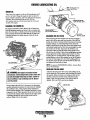
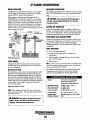
Siphon-Break
For installations where the water injected exhaust elbow is
close to or will be below the vessels waterline, provisions
must be made to install a siphon-break in the raw water
supply hose to the water injected exhaust elbow. The siphonbreak provides an air vent in the raw water cooling system to
prevent raw water from filling the exhaust system and the
engine's cylinders when the engine is shutdown.
A
CAUTION: Failure·to use a siphon-break when
the exhaust manifold injection port is at or below the
load waterline will result in raw water damage to the
engine and possible flooding of the boat.
If you have any doubt about the position of the water-
injected exhaust elbow relative to the vessels waterline under
the vessels various operating conditions, install a siphonbreak. This precaution is necessary to protect your engine.
The siphon-break must be installed in the highest point of a
hose that is looped a miuimum of 20 inches (51cm) above
the vessels waterline. This siphon-break must always be
above the waterline during all angles of vessel operation to
prevent siphouing.
NOTE: A siphon-break requires periodic inspection and
cleaning to ensure proper operation. Failure to properly
maintain a siphon-break can result in catastrophic engine
damage. Consult the siphon-break manufacturer for proper
maintenance.
SIPHON-BREAK WITH STAINLESS
LOOPFOR 1" HOSE
PART NO. 044010
-.,y
WESTERBEKE
Engines & Generators
4
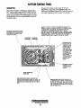
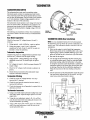
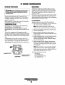
ADMIRAL CONTROL PANEL
DESCRIPTION
When the engine is shut down with the key switch turned off,
the water temperature gauge will continue to register the last
temperature reading indicated by the gauge before electrical
power was turned off. The oil pressure gauge will fall to zero
when the key switch is turned off. The temperature gauge
will once again register the engine's true temperature when
electrical power is restored to the gauge.
A separate alarm buzzer with harness is supplied with every
Admiral Panel. The installer is responsible for electrically connecting the buzzer to the four-pin connection on the engine's
electrical harness. The installer is also responsible for installing
the buzzer in a location where it will be dry and where it will
be audible to the operator should it sound while the engine is
running. The buzzer will sound when the ignition key is turned
on and should silence when the engine has started and the
engine's oil pressure rises above 15 psi (1.1 kg/em').
TIlls manually-operated control panel is equipped with a
KEY switch and RPM gauge with an ELAPSED TIME
meter which measures the engine's running time in hours and
in 1110 hours. The panel also includes a WA1ER TEMPERATIJRE gauge which indicates water temperature in degrees
Fahrenhei~ an OIL PRESSURE gauge which measures the
engine's oil pressure in pounds per square inch, and a DC
control circuit VOLTAGE gauge which measures the system's voltage. All gauges are illuminated when the key
switch is turned on and remain illuminated while the engine
is in.operation. The panel also contains two rubber-booted
pushbuttons, one for PREHEAT and one for START.
OIL PRESSURE GAUGE: THIS GAUGE IS GRADU·
ATED IN POUNDS PER SQUARE INCH (PSI) AND IS
ILLUMINATED WHILE THE KEY SWITCH IS TURNED
ON. THE ENGINE'S NORMAL OPERATING OIL
PRESSURE RANGES BETWEEN 30 - 60 psi
(2.1- 4.2 kg/em').
WATER TEMPERATURE GAUGE: THIS GAUGE IS
GRADUATED IN DEGREES FAHRENHEIT AND IS
ILLUMINATED WHILE THE KEY SWITCH IS
TURNED ON. THE ENGINE'S NORMAL OPERATING
TEMPERATURE IS 170'- 190' F (77' -SS'C).
RPM GAUGE: REGIS·
TERS REVOLUTIONS
PER MINUTE OFTHE
ENGINE AND CAN BE
RECALIBRATED FOR
ACCURACY FROM THE
REAR OF THE PANEL.
--;iFD----_
__-1\1" SWITCH: PROVIDES
HOURMETER:
REGISTERS ELAPSED
TIME, AND SHOULD BE
USED AS A GUIDE FOR
THE MAINTENANCE
SCHEDULE.
POWER ONLYTO THE
INSTRUMENT PANEL
CLUSTER.
,
PREHEAT
PRESSED, ENERGIZES THE
ALTERNATOR'S EXCITER, THE FUEL LIFT PUMP, THE
FUEL SOLENOID ON THE INJECTION PUMP, AND THE
ENGINE'S GLOW PLUGS. IT BYPASSES THE ENGINE'S
OIL PRESSURE ALARM SWITCH. IN ADDITION, THIS
BUTTON ENERGIZES THE START BUTTON.
START BUTTON: WHEN PRESSED, ENERGIZES THE
STARTER'S SOLENOID WHICH CRANKS THE ENGINE.
THIS BUTTON WILL NOT OPERATE ELECTRICALLY
UNLESS THE PREHEAT BUTTON IS PRESSED AND HELD
AT THE SAME TIME.
~
~
'BATIERYIS
SHOULD SHOW
•
,
~
:
...,:
'-.-
,
.,
AUTOMATIC ALARM SYSTEM
COOLANT TEMPERATURE ALARM: AN ALARM BUZZER HAS BEEN
SUPPLIED WITH THE INSTRUMENT. PANEL. IF THE ENGINE'S COOLANT
REACHES 210' F (99'C), THIS SWITCH WILL CLOSE SOUNDING THE
ALARM WHICH WILL EMIT A CONTINUOUS SIGNAL.
OIL PRESSURE ALARM: AN OIL PRESSURE ALARM SWITCH IS
LOCATED OFF THE ENGINE'S OIL GALLERY. THIS SWITCH MONITORS
THE ENGINE'S OIL PRESSURE. SHOULD THE ENGINE'S OIL PRESSURE
FALL TO 5- 10 psi (0.4 - 0.7 kg/em'), THE SWITCH WILL CLOSE SOUND·
ING THE ALARM. IN THIS EVENT, THE ALARM WILL EMIT APULSATING
SIGNAL
~
WESTERBEKE
Engines. & Generators
5
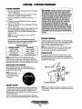
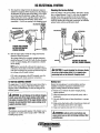
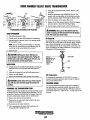
CAPTAIN CONTROL PANEL
The panel also includes an alarm buzzer for low OIL
PRESSURE or high COOLANT 1EMPERATURE. The
RPM gauge is illuminated when the KEY switch is turned on
and remains illuminated while the engine is in operation.
DESCRIPTION
This manually-operated control panel is equipped with a
KEY switch, an RPM gauge, PREHEAT and START buttons, an INS1RUMENT TEST button and three indicator
lamps, one for AL1BRNATOR DISCHARGE, one for low
OIL PRESSURE, and one for high ENGINE COOLANT
1EMPERATURE.
ALARM: THE ALARM WILL SOUND IF THE ENGINE'S DIL PRESSURE FALLS
BELOW 5 -10 psi (0.4 - 0.7 kglcm').IN THIS EVENT, THE ALARM WILL EMIT A
PULSATING SIGNAL. THE ALARM WILL ALSO SOUND IF THE COOLANT
TEMPERATURE IN THE FRESHWATER COOLING CIRCUIT RISES TO
210°F (9goC). IN THIS EVENT, THE ALARM WILL EMIT A CONTINUOUS SIGNAL.
NOTE: THE ALARM WILL SOUND WHEN THE KEY SWITCH IS TURNED ON. THIS
SOUNDING IS NORMAL. ONCE THE ENGINE STARTS AND THE ENGINE'S OIL
PRESSURE REACHES 15 psi (1.1 kglcm'), THE ALARM WILL SILENCE.
RPM GAUGE: REGISTERS REVOLUTIONS
PER MINUTE OF THE ENGINE AND CAN BE
RECALIBRATED FOR ACCURACY FROM
THE REAR OFTHE PANEL.
TURE CONTROL CIRCUITS. WHEN PRESSED,
THE ALTERNATOR, THE
OIL PRESSURE, AND
THE WATER TEMPERATURE INDICATOR
LIGHTS ILLUMINATE IN
ADDITION TO SOUNDING THE ALARM
BUZZER.
- - - - - - - """ SWITCH: PROVIDES
POWER ONLYTO THE
INSTRUMENT PANEL
CLUSTER.
WATER TE~IPERATUIRE /
ALARM LIGHT
START BUTTON: WHEN PRESSED, ENERGIZES THE
STARTER'S SOLENOID WHICH CRANKS THE ENGINE. THIS
BUTTON WILL NOT OPERATE ELECTRICALLY UNLESS THE
PREHEAT BUTTON IS PRESSED AND HELD AT THE SAME
TIME.
Engines. & Generators
6
'PO""",,, o,"m,.· WHEN PRESSED, ENERGIZES THE
ALTERNATOR'S EXCITER, THE FUEL LIFT PUMP, THE FUEL
SOLENOID ON THE INJECTION PUMp, AND THE ENGINE'S
GLOW PLUGS, AND BYPASSES THE ENGINE'S OIL PRESSURE ALARM SWITCH. IN ADDITION, THIS BUTTON ENERGIZES THE START BUTTON.
DIESEL FUEL, ENGINE OIL AND ENGINE COOLANT
DIESEL FUEL
ENGINE COOLANT
Use a diesel fuel that meets the requirements of No. 2-D
SAE J 3 [3 and has a Cetane rating of #45 or higher grade of
diesel fuel according to ASTM D975
WESTERBEKE recommends a mixture of 50% antifreeze
and 50% distilled water. Distilled water is free from the
chemicals that can corrode internal engine surfaces.
The antifreeze performs double duty. It aHows the engine to
nm at proper temperatures by transferring heat away from
the engine to the coolant, and lubricates and protects the
cooling circuit from rust and corrosion. Look for a good
quality antifreeze that contains Supplemental Cooling
Additives (SCAs) that keep the antifreeze chemicalJy
balanced, crucial to long term protection.
The distilled water and antifreeze should be premixed before
being poured into the cooling circuit.
Care Of The Fuel Supply
Use only clean diesel fuel! The clearance of the components
in your engines fuel injection pump is very critical; invisible
dirt particles which might pass through the primary and secondmy filters can damage these finely machined parts. It is
important to buy clean fuel, and keep it clean. The best fuel
can be rendered unsatisfactory by careless handling or
improper storage facilities. To ensure that the fuel going into
the tank for your engine's daily use is clean and pure, the
following practice is advisable:
Purchase a well-known brand of fuel. The use of additives
to combat BACTERIAL growth in the fuel tank is
recommended such as Bio-Bor and an additive such as
Diesel Kleen + Centane Boost to help restore lubricity back
into the diesel fuel when an Ultra Low Sulfur diesel is being
used.
Install and regularly service a good, visual-type fuel
filtedwater separator between the fuel tank and the engine.
The Raycor 500 MA or 230 RMAM are good examples of
such filters. A 10 micron filter element is recommended.
NDTE: Lookfor the new environmentally-friendly long lasting
antifreeze that is now available.
PURCHASING ANTIFREEZE
Rather than preparing the mixture, WESTERBEKE
recommends buying the premixed antifreeze so that so that
when adding coolant the mixture will always be correct.
There are two common types of antifreeze, Ethylene Glycol
(green) and Propylene Glycol (red/purple), either can be used
but do not mix the two and if changing from one to another,
flush the engine thorougbly.
Premixed antifreeze for DIESEL Engines:
Specification #ASTM D53456.
ENGINE OIL
Use a heavy duty diesel oil with an API classification of CF,
CG-4, CH-4 or CIA. Change the engine oil and filter after an
initial 50 hours of break-in operation.Then follow the oil and
filter change intervals as specified in the MAINTENANCE
SCHEDULE in this manual. Westerbeke Corporation does
not approve or disapprove the use of synthetic oils. If
synthetic oils are used, engine break-in must be performed
using conventional oil. Oil change intervals must be as listed
in the MAINTENANCE SCHEDULE section of this
manual and not be extended if synthetic oils are used.
MAINTENANCE
Change the engine coolant every five years regardless of the
number of operating hours as the chemical additives that
protect and lubricate the engine have a limited life.
COOLANT RECOVERY TANK
The coolant recovery tank aIJows for the expansion and
contraction of the engines coolant during engine operation
without introducing air into the system. This recovery tank is
provided with fresh water cooled models and with the fresh
water coolant conversion kit and must be installed before
operating the engine.
NOTE: The information above supersedes all previous
statements regarding synthetic oil.
SAE OIL VISCOSITY GRADE
For all temperature ranges: SAB l5W -40 or SAB IOW-40.
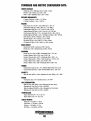
RECOMMENDED RPM RANGES
-
Cruise RPM
2000-2500 rpm
Models 55BIFour and 55CIFour
2000-2400 rpm
Model 55DIFour
Maximum RPM (propeller loaded)
Models 55BIFour and 55CIFour
2950-3000 rpm
Model 55DIFour
2550-2600 rpm
Engines & Generators
7
PREPARATIONS FOR INITIAL START-UP
PRESTART INSPECTION
Before starting your engine for the first time or after a
prolonged layoff, check the following items:
D Check the engine oil level. Add oil to maintain the level
at the high mark on the dipstick.
D Thrn on the fuel supply, then check the fuel supply and
examine the fuel filter/water separator bowl for
contaminants.
D Check the transmission fluid level.
D Check the DC electrical system. Inspect wire connections
and battery cable connections. Make certain the positive
(+) battery cable is connected to the starter solenoid and
the negative (-) cable is connected to the engine ground
stud (this location is tagged).
D Check the coolant level in both the plastic recovery tank
and at the manifold.
"A<"~P~
19~ti
":.;:.;j'!j ~1N'"~ ~
NOTE: If the engine luls not yet been filled with coolant,
refer to the COOUNG SYSTEM section of this manual.
D Visually examine the engine. Look for loose or missing
COOLANT EXPANSION
parts, disconnected wires, and unattached hoses. Check
the threaded connections and engine attachments.
D Make certain there is proper ventilation around the
engine. An ample supply is necessary for proper engine
performance.
D Make sure the mounting installation is secure.
D Ensure the propeller shaft is securely attached to the
transmission.
D Open the thru-hull and make certain raw water is primed
to the raw water strainer.
TO THERMOSTAT
HOUSING
TOP Oil Fill
DIPSTICK
....v'
WESTERBEKE
Engines' & Generators
8
STARTING· STOPPING PROCEDURE
STARTING PROCEDURE
A CAUTION: Prolonged cranking intervals without
1. Place the transmission in neutral and advance the throttle
control to slightly open.
2. Thrn the KEY SWITCH to the ON position (2 o'clock).
(If the panel is energized, the gauges are on.)
3. Depress the PREHEAT BUTTON, and hold for 5 - 10
seconds.
4. Continue to hold the PREHEAT BUITON and depress
the START BUTTON.
5. Release the START BUITON and PREHEAT BUTTON
once the engine starts.
6. With the engine running, check the instruments for proper
oil pressure and battery charging voltage. The water
temperature will rise slowly and then stabilize when the
thennostat opens.
the engine starting can result in the engine exhaust
system filling with raw water. This may happen because
the pump Is pumping raw water through the raw water
cooling system during cranking. This raw water can
enter the engine's cylinders by way of the exhaust
manifold once the exhaust system mls. Prevent this
from happening by closing the raw water supply
through-hull shutoff, draining the exhaust muffler, and
co"ecting the cause of the excessive engine cranking.
Engine damage resulting from raw water entry is nota
warrantable issue; the owner/operator should keep this
in mind.
NOTE: Never attempt to engage the starter while the
engine is running.
STOPPING PROCEDURE
It is important to closely monitor the panel gauges.
Become aware of the normal engine readings and take
immediate action if these readings start to vlll)'.
To stop the engine, bring the throttle to an idle position and
place the transmission in neutral. Allow the engine to idle for
a few moments to stahilize temperatures, then shut the
engine down by turning off the key switch.
NOTE: Make certain this key switch is in the OFF position
(12 o'clock). If the key switch is left ON, the alarm will
sound, warning you the key is in the ON position.
Temperature/Preheat
Atmospheric Temperalure
41'F(5'C) or higher
41'F(5'C) to 23'F (-5'C)
Preheating Time
Approx. 10 seconds
Approx. 15 seconds
23'F(-5'C) or lower
Limit of conlinuous use
Approx. 20 seconds
30 seconds before cranking
FAILURE TO STOP
In the unusual situation that the key switch fails to tum the
engine off, shutdown can be accomplished by pressing back
the mechanical stop lever. This stop lever is located next to the
throttle lever on the engine.
NOTE: The START button will not energize unless the
PREHEAT button is depressed. Depressing the PREHEAT
button activates the glow plugs in the cylinder head so use the
PREHEAT intermittently to avoid overheating the glow plugs.
Starting Under Cold Conditions
Make certain the lubricating oil is appropriate for the .
prevailing temperature. Us~oil with an API Specification
of CF or CG-4, SAE 15W-40.
. -
NOTE: When starting:
A voltag,tdrop will. occur
when the preheat button
is depressed.
12
•..
ENGINE STOP LEVER·---
,
14
~6
\
r..a,
I.-J
0
'\,
"1,;;:,
.'
VOI-:TS
I
, IDLE
SPEED- ADJUSTMENT
- -.
_. .
-~---
FAILURE TO START
NOTE: Once the engine is shutdown, investigate why the key
switch failed to properly shutdown the engine when turned in
the offposition.
If the engine fails to slatt when the start blltton is pressed for
5 seconds, wait for at least 30 seconds and repe~t the starting
procedure. Make certain the transmission confrQ! is in the
neutral position as some engines have a neutral safety switch to
prevent starting in gear.
Never run the starter for more then 30 seconds. If the engine
fails to start, refer to the TROUBLESHOOTING CHART in this
"tOY'
WESTERBEKE
Engines & Generators
9
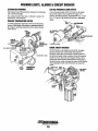
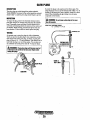
WARNING LIGHTS, ALARMS & CIRCUIT BREAKER
ALTERNATOR WARNINGS
LOW OIL PRESSURE ALARM SWITCH
The Captain Control Panel indicates alternator low discharge
with a red warning light.
The Admiral Control Panel uses a voltmeter to monitor the
performance of the alternator.
A low oil pressure alarm switch is located on the engine
block. This switch's sensor monitors the engine's oil
pressure. Should the engine's oil pressure fall to 5 - 10 psi
(0.4 - 0.7 kg/cm'), this switch will activate a pulsating
alarm.
COOLANT TEMPERATURE SWITCH
A coolant temperature switch is located on the thermostat
housing. This switch will activate a continuous alarm if
the coolant's operating temperature reaches approximately
21O'F (99'C).
'OIL PRESSURE ALARM
SWITCH
'.~
TO r.nri:rrlnl
ENGINE CIRCUIT BREAKER
TO ALARM BUZi.'E[;>l!l>·
The DC harness on the engine is protected by an engine
mounted manual reset circuit breaker (20 amps DC).
Excessive current draw or electrical overload anywhere in
the instrument panel wiring or engine wiring will cause the
breaker to trip. In this event most engines will shut down
because the opened breaker disconnects the fuel supply. If
this should occur, check and repair the source of the problem.
After repairing the fault, reset the breaker and restart the
. engine.
""""~<u,. CIRCUIT
BREAKER
TWO
WIRES
Engines' & Gen!1rators
10
ENGINE BREAK-IN PROCEDURE
DESCRIPTION
Although your engine has experienced a minimum of one
hour of test operations at the factory to make sure accurate
assembly procedures were followed and that the engine operated properly, a break-in time is required. The service life of
your engine is dependent upon how the engine is operated
and serviced during its initial 50 hours of use.
Breaking-in a new engine basically involves seating the piston rings to the cylinder walls. Excessive oil consumption
and smoky operation indicate that the cylinder walls are
scored, which is caused by overloading the engine during the
break-in period.
Your new engine requires approximately 50 hours of initial
conditioning operation to break in each moving part in order
to maximize the performance and service life of the engine.
Perform this conditioning carefully, keeping in mind the following:
1. Start the engine according to the STARTING PROCEDURE section. Run the engine at fast idle while checking
that all systems (raw water pump, oil pressure, battery
charging) are functioning.
2. Allow the engine to warm up (preferably by running at
fast idle) until the water temperature gauge moves into
the 130 - 140'P (55 - 60'C) range.
3. While using the vessel, run the engine at various engine
speeds for the first 25 hours. Avoid prolonged periods of
idling.
4. Avoid rapid acceleration, especially with a cold engine.
5. Use caution not to overload the engine. The presence of a
grey or black exhaust and the inability of the engine to
reach its full rated speed are signs of an overload.
,6. During the next 25 hours, the engine may be operated at
varying engine speeds, with short runs at full rated rpm.
Avoid prolonged idling during this break-in period.
CHECKLIST
o Monitor the control panel gauges.
o .Check for leaks of fuel and engine oil.
o Check for abnormal noise such as knocking, friction,
o
vibration and blow-back sounds.
Confirm exhaust smoke:
When the engine is cold - white smoke.
When the engine is warm - almost smokeless.
When the engine is overloaded - some black smoke and soot.
NOTE: See the TRANSMISSION section of this manualfor
break-in information on your transmission.
Engines. & Generators
11
THE DAILY OPERATION
CHECKLIST
FAILURE TO START
Follow this check list each day before starting your engine.
, D Visually inspect the engine for fuel, oil, or water leaks.
D Check the oil level (dipstick).
D Check the coolant level in the coolant recovery tank.
Periodically check the manifold coolant level.
D Check the transmission fluid level.
D Check your fuel supply.
D Look for clean fuel in the fuel filter/water separator
t\'ansparent bowl.
D Check for loose wires at the alternator and make sure its
mounting is secure.
D Check the starting batteries (weekly).
D Check drive belts for wear and proper tension (weekly).
D Visually inspect the raw water pump for leakage.
If the engine fails to start when the start button is pressed for
5 seconds, wait for at least 30 seconds and repeat the starting
procadure. Make certain the transmission control is in the
neutral position as some engines have a neutral safety switch
to prevent starting in gear.
Never run the starter for more than 30 seconds. If the engine
faiIs to start, refer to the TROUBLESHOOTING CHART in
this manual.
A CAUTION: Prolonged cranking intervals without the
engine starting can result in the engine exhaust system
tilling with raw water. This may happen because the
pump is pumping raw water through the raw water
cooling system during cranking. This raw water can
enter the engine's cylinders by way of the exhaust
manifold once the exhaust sytem fills. Prevent this
from happening by closing the raw water supply
through-hull shutoff, draining the exhaust muffler, and
correcting the cause of the excessive engine cranking.
Engine damage resulting from raw water entry is not a
warrantable issue; the owner/operator should keep this
STARTING THE ENGINE
NOTE: See STARTING/STOPPING PROCEDURE in this
manual for more detailed instructions.
I, Put the transmission in neutral, throttle advanced.
in mind.
NOTE: Hydraulically operated transmissions have a
neutral safety switch through which the starter solenoid
energizing circuit passes. This switch is open when the
transmission is in gear so the staner solenoid will not
Stopping Procedure
energize.
To stop the engine, bring the throttle to an idle position and
place the transmission in neutral. Allow the engine to idle for
a few moments to stabilize temperatures. Then shut the
engine down by turuing off the key switch.
'2. Turn the KEY SWITCH to the ON position (2 o'clock).
(If the panel is energized, the gauges are on.)
3. Depress the PREHEAT BuriaN; and hold for 5 - 10
seconds.
t-;
NOTE: Make certain this key switch is in the OFF
position(12o'clock}.lfthe key switch is left ON, the
energized instrument panel will put a drain on the battery.
4. Continue to hold the PREHEATBUTTON and depress
the START BUTTON.
5. Release the START BUTTON and PREIIEATBUTTON
once the engine statts.
6. With the engine running, check the instruments for proper
oil pressure and battery charging voltige. The water
temperature will rise slowly and then stabilize when the
thermostat opens.
NOTE: Never attempt to engage the starter while the
engine is running.
Itisimporttint to closely m'onitor the panel gauges.
Become aware of the normal engine readings and take
immedWie action if these readings start to vary.
12
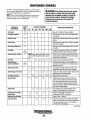
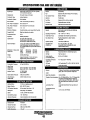
MAINTENANCE SCHEDULE
In order to use this Maintenance Schedule, it will be neces-
A WARNING: Never attempt to perform any service
sary to log your engine hours. Use your engine hounneter or
record your engine hours by running time.
NOTE: Many of the following maintenance procedures are
simple but others are more difficult and may require the
expert !mowledge of a service mechanic.
SCHEDULED
MAINTENANCE
CHECK
EACH
DAY
while the engine is running_ Wear the proper safety
equipment such as goggles and gloves, and use the
correct tools for each job. Disconnect the battery
terminals when servicing any of the engine's DC
electrical equipment.
HOURS OF OPERATION
50
100
250
500
MAINTENANCE DESCRIPTION
750 1000 1250
Diesel No.2 rating of 45 cetane or higher.
Fuel/Water Separator
0
0
Engine 011 Level
0
Oil level should indicate between MAX. and LOW on
dipstick.
Coolant Level
0
Check at recovery tank; if empty, check at manifold.
Add coolant if needed.
Transmission Fluid Level
0
Fluid level should indicate between MAX and LOW
on dipstick.
0
Inspect for proper tension (3/8" to 1/2" deflection)
and adjust if needed. Check belt edges for wear.
Fuel Supply
Drive Belts
Check for water and dirt in fuel (drain/replace filter
if necessary).
weekly
Visual Inspection of Engine
0
Check for fuel, oil and water leaks. Inspect wiring
and electrical connections. Keep bolts & nuts tight.
Check for loose belt tension.
NDTE: Keep engine surface clean. Dirt and
oil will inhibit the engine's ability to remain
cool.
0
Fuel Filter
Starting Batteries
(and House Balteries)
0
0
0
0
Change at 50 hours then every 250 hours.
Check electrolyte levels every 50 operating hours
and make sure connections are very tight. Clean off
excessive corrOSion.
0
Heat Exchanger Zinc Anode .
0
0
0
Fuel/Water Separator
0
0
Engine Hoses
Throttle and Transmission
Control Cable
0
Adjust Engine Idle Speed
0
Raw Water Pump
0
weekly
Engine Oil and Filter
Exhaust System
0
0
0
0
0
0
Initial engine oil & filter change at 50 hours, then
change both every 250 hours or once a season.
0
0
0
0
0
Inspect zinc anode, replace if needed. Clear the heat
exchanger end of zinc anode debris.
0
0
0
0
0
0
0
0
Change filter every 200 hours.
0
0
0
0
0
Hose should be hard & tight. Replace if soft or
spongy. Check and tighten all hose clamps.
0
Check for loose fittings, colter pins, etc.
Lubricate with WD-40 or equivalent.
0
0
Initial check at 50 hours, then every 250 hours.
Inspect for leaks. Check anti-Siphon valve operation. Check the exhaust elbow for carbon and/or
corrosion buildup on inside passages; clean and
replace as necessary. Check that all connections are
tight. Check casting integrity.
Adjust to 750 -1000 rpm
0
0
0
Engines & Generators
13
Remove the pump cover and inspect the impeller,
gasket, cam and cover for wear. Check the bearings
and seals (the shaft can turn, but not wobble).
Lubricate when reassembling.
(contmued)
MAINTENANCE SCHEDULE
NOTE: Use the engine hounneter gauge to log your engine hours or record your
engine hours by running time.
SCHEDULED
MAINTENANCE
CHECK
EACH
DAY
HOURS OF OPERATION
50
100
250
0
Coolant System
0
DC Alternator
0
Air Intake Filter
0
MAINTENANCE DESCRIPTION
500 750 1000 1250
0
0
0
0
Transmission Oil Cooler
0
0
Drain, flush, and refill cooling system with
appropriate antifreeze mix.
0
Check DC charge from alternator. Check mounting
bracket; tighten electrical connections.
0
Clean every 100 operating hours.
Remove; have professionally cleaned and pressure
tested.
0
Engine Transmission
Damper Plate
Chattering at idle and low rpms is an indication
of damper plate wear. l1"emove and replace.
0
'Fuel Injectors
Check and adjust injection opening pressure and
spray condition.
'Starter Motor
0
0
Check solenoid and motor for corrosion. Remove
and lubricate. Clean and lubricate the starter motor
pinion drive.
'Preheat Circuit
0
0
Check operation of preheat solenoid. Remove and
clean glow plugs. Reinstall with anti-seize
compound on threads.
'Engine Cylinder
Compression
0
0
Check compression pressure and timing (see Engine
Adjustments).
'Adjust the Valve Clearances
0
0
'Heat Exchanger
0
Lubricate Panel Key Switch
with "Lockeze"
Transmission Fluid
0
0
Adjust Valve Clearances (see ENGINE
ADJUSTMENTS).
0
Remove, have professionally cleaned and pressure
tested.
0
0
0
0
0
At first 100 hours, then each year at winterizing.
0
0
0
0
0
Initial fluid change at 25 hours, then every
300 hours or at winterizing.
'WESTERBEKE recommends this service be performed by an authorized mechanic.
Engines & Generators
14
DIESEL FUEL
FUEL SYSTEM
20A CIRCUIT
Use No:2-D (SAE J313) diesel fuel with a Cetane rating
ofll45 or higher. Grade of diesel fuel according to
ASTMD975.
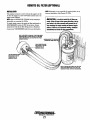
FUEL FILTER/WATER SEPARATOR
A primary fuel filter of the water separating type must be
installed between the fuel tank and the engine to remove
water and other contaminant's froni the fuel before they can
be carried to the fuel system on the engine.
Most installers include a fuel filter/water separator with the
installation package as they are aware of the problems that
contaminant's in the fuel can cause.
A typical fuel filter/water separator is illustrated below. This
is the Rayeor Model 500 MA. Keep in mind that if a water
separator type filter is not installed between the fuel supply
tank and engine-mounted fuel system, any water in the fuel
will affect the fuel pump, engine filter, and injection equipment. The owner/operator is responsible for making certain
the fuel reaching the engine's injection equipment is free of
impurities. This process is accomplished by installing and
maintaining a proper fuel filter/water separator.
EXTERNAL FUEL FILTER
PART NO, 2144B
LIGHTLY WIPE
WITH CLEAN FUEL,~---»-i~~~
THE a-RING GASKET
ONLY NEEDS TO BE
REPLACED IF IT SHOWS
SIGNS OFWEAR
PRE·FILL
WITH FRESH ,ute--
TYPICAL
FUEL
FILTER
FUEL FILTERS
The fuel injection pump and the fuel injectors are precisely
manufactured and they must receive clean diesel fuel, free
from water and dirt. To ensure this flow of clean fuel, the fuel
must pass through at least two fuel filters, a fuel filter/water
separator and the engine's spin-on fuel filter. Visually inspect,
clean, and change these filters according to the maintenance
schedule in this manual.
(OWNER INSTALLED)
FUEL INJECTION PUMp
The fuel injection pump is a very important component of
the diesel engine, requiring the utmost care in handling.
The fuel injection pump has been thoroughly bench-tested
and the owner-operator is cautioned not to attempt to service
it. If it requires servicing, remove it and take it to an
authorized fuel injection pump service facility. Do not
attempt to disassemble and repair it.
ENGINE FUEL FILTER
Periodically check the fuel connections and the bowl for
leakage. Replace the filter element after the first 5Q hours
. then follow the MAINTENANCE SCHEDULE.
Changing the Fuel Filter Element
FUEL LIFT PUMP
Refer to the illustration above.
1. Shut off the fuel supply.
2. Thrn the fuel filter bowl counterclockwise to remove.
3. Pull the filter element straight down and off.
4. Inspect both O-rings and replace if worn.
5. Wipe the O-rings with clean fuel and snap the new filter
up into place over the small O-ring.
6. Clean off the filter bowl and threads. (The bowl can be
pre-filled with fuel). Screw the bowl into place when the
O-ring contacts the housing. Tighten the bowl firmly by
hand.
7. The key-on preheat sequence will allow the lift pump to
.fill the fuel filter.
S. Run the engines and inspect for leaks.
Periodically check the fuel connections to and out of the
pump and make sure that no leakage is present and that the
fittings are tight and secure. The DC ground connection at
one of the pumps mounting bolts should be clean and well
secured 'by the mounting bolt to ensure proper pump
operations.
When energized thru the preheat circuit, the fuel lift pump
will purge air from the fuel system and provide a continuous
flow of fuel as the engine is running.
A small fuel filter has been added to the incoming fuel
line to ensnre that filtered fuel enters the fuel Iiftpnmp.
,.yo
WESTERBEKE
Engines & Generators
15
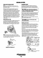
COOLING SYSTEM
FRESH WATER COOLING CIRCUIT
CHANGING COOLANT
NOTE: Refer to the ENGINE COOLANT page for the
recommended antifreeze and water mixture to be used as
the fresh water coolant.
The engine's coolant must be changed according to the
MAINTENANCE SCHEDULE. If the coolant is allowed to
become contaminated, it can lead to overheating problems.
Fresh water coolant is pumped through the engine by a
circulating pump, absorbing heat from the engine. The
coolant then passes through the thennostat into the manifold,
to the heat exchanger where it is cooled and returned to the
engine block via the suction side of the circulating pump.
When the engine is started cold, external coolant flow is
prevented by the closed thennostat (although some coolant
flow is bypassed arouud the thennostat to prevent the exhaust
manifold from overheating). As the engine wanns up, the
thennostat gradually opens, allowing full flow of the engine's
, coolant to flow unrestricted to the external portion of the
cooling system.
CoolantRecovery Tank
A coolant recovery tank allows for engine coolant expansion
'" al\d contraction during engine operation, without any
significant loss of coolant and without introducing air into
the cooling system. This tank should be located at or above
the engine manifold level and should be easily accessible.
COOLANT '. '.'w,"'"
RECOVERY
TAN,K
NOTE: Periodically check the condition of the manifold
pressure cap. Ensure that the upper and lower rubber seals
are in good condition and check that the vacuum valve opens
and closes tightly. Carry a spare cap.
A CAUTION: Proper cooling system maintenance is
critical; a substantial number of engine failures can be
traced back to cooling system corrosion.
Drain the engine coolant by removing'the drain plug on the
engine block and opening the manifold pressure cap. Flush
the system with fresh water, then reinstall the drain and start
the refill process. Refer to the illustration below.
NOTE: The drain petcock on the heat exchanger can also be
used to help drain engine coolant.
A WARNING: Beware of the hot engine coolant.
Wear protective gloves.
Refilling the Coolant
After replacing the engine block drain plug, close the heat
exchanger'S coolant petcock. Then run the engille at idle and
slowly poor clean, premixed coolant into the manifold.
Monitor the coolant in the manifold and add as needed. Fill
the manifold to the filler neck and install the manifold
pressure cap.
Remove the cap on the coolant recovery tank and fill with
coolant mix to halfway between LOW and MAX and replace
the cap. Run the engine and observe the coolant expansion
flow into the recovery tank.
After checking for leaks, stop the engine and allow it to cool.
Coolant should draw back into the cooling system as the
engine cools down. Add coolant to the recovery tank if
needed and check the coolant in the manifold. Clean up any
spilled coolant.
CHECKING THE PRESSURE CAP
I COOLANT
~
WESTERBEKE
Engines & Generators
16- .
DRAIN
COOLING SYSTEM
THERMOSTAT
RAW WATER INTAKE STRAINER
A thennostat, located near the manifold at the front of the
engine, controls the coolant temperature as the coolimt
continuously flows through the closed cooling circuit. When
the engine is first started, the closed thermostat prevents
coolant from flowing (some coolant is by-passed through a
hole in the thermostat to prevent the exhaust manifold from
overheating). As the engine warms up, the thermostat
gradually opens. The thermostat is accessible and can be
. checked, cleaned, ·or replaced easily. Carry a spare thermostat
and gasket
NOTE: Always install the strainer at or below the waterline so
the strainer will always be self-priming.
A clean raw water i,ntake strainer is a vital component of the
engine's cooling system. Include a visual inspection of this
strainer when making your periodic engine check. The water
.in the glass ·shoufd be clear.
Perform the following maintenance after every 100 hours of
operation:
1.
2.
3.
4.
Replacing the Thermostat
Close the raw water seacock.
Remove and clean the strainer filter.
Ciean the glass.
Replace the sealing washer if necessary.
5. Reassemble and install the strainer.
6. Open the seacock.
7. Run the engine and check for leaks.
Remove the cap screws and disassemble the therrrio~tat
housing as shown. When installing the new thermostat and
gasket, apply a thin coat of sealant on both sides of the
gasket before pressing it into place. Do not over-tighten the
cap screws.
Run the engine and check for normal temperatures and that
there are no leaks at the thermostat housing.
NOTE: Also follow the above procedure after having run hard
aground.
If the engine temperature gauge eyer shows a higher than .
normal reading, the cause may be that silt, leaves or grass
may have been caught up in the strainer, slowing the flow of
raw water through the cooling system.
P~~~/~~~~;;;;~~~
AIR
FORBLEED
PUSHING AIR FROM THE
COOLING SYSTEM
COOLANT
TEMPERATURE
SENDER
WASHER
HI-TACK SEALANT
THERMOSTAT
ASSEMBLY
THERMOSTAT
PART NO. 47571
FILTER
INSPECTAND
CLEAN EVERY
100 HOURS
BY·PASS HOLE
WATE:;Riiii~;
TYPICAL RAW
(OWNER INSTALLED)
INCOMING
RAW WATER
SEACOCK -r'li(l"
~
...v WESTERBEKE
Engines· & Generators
17
COOLING SYSTEM
RAW WATER CODLING CIRCUIT
RAW WATER PUMP
The raw water flow is created by a positive displacement
impeller pump. This pump draws water directly from the
ocean, lake, or river from a thru-hull opening through a hose
to the water strainer. The raw water passes from the strainer
through the pump to the heat exchanger (through the heat
exchanger tubes) where it cools the engine's circulating fresh
water coolant. The raw water is then discharged into the
water-injected exhaust elbow, mixing with, and cooling the
exbaust gasses. This mixture of exbaust gas and raw water is
driven through 'the stem tube and overboard.
The raw water pump is a self-priming, rotary pump with a
non-ferrous housing and a Neoprene iropeller. The iropeller
has fle«ible blades which wipe against a curved earn plate
within the iropeller housing, producing the pumping action.
no account should this pump be run dry. There should
always be a spare iropeller and impeller cover gasket aboard
(an iropeller kit), Raw water pump iropeller failures occur
when lubricant (raw water) is not present during engine
operation. Such failures are not warrantable, and operators
are cautioned to make sure raw water flow is present at
start-up. The raw water pump should be inspected
periodicallY for broken or tom iropeller blades. See
MAINTENANCE SCHEDULE,
HEAT EXCHANGER
Cool raw water flows through the inner tubes of the heat
exchanger. As the engine coolant passes around these tubes,
the heat of the internal engine is conducted to the raw water
which is then pumped into the exhaust system and discharged, The engine coolant (now cooled) flows back
through the engine and the circuit repeats itself,
The engine coolant and raw water are independent of each
other; this keeps the engine's water passages clean from the
harmful deposits found in raw water.
Heat Exchanger Service
After approxiroately 1000 hours of operation, remove, clean
and pressure test the engine's heat exchanger. (A local
automotive radiator shop should be able to clean and test the
heat exchanger.)
On
NOTE: Should a failure occur with the pumps intern£ll parts
(seals and bearings), it may be more cost efficient to
purchase a new pump and rebuild the original pump as
a spare.
Changing the Raw Water Pump Impeller
Close the raw water intake valve. Remove the pump cover
and, using an iropeller puller, screw drivers, or pliers,
carefully pry the iropeller out of the pump. Install the new
iropeller and gasket. Move the blades to conform to the
curved earn plate and push the iropeller into the pumps housing. When assembling, apply a thin coating of lubricant to
the impeller and gasket. Qpen the raw water intake valve.
A CAUTION: If any of the vanes have broken off the
impeller, they must be found to prevent blockage in the
cooling circuit. They often can be found in the heat
exchanger.
IMPELLER SCREW
FITS INTO THE SLOT
IN THE SHAFT
TO TRANSMISSION COOLER
HEAT ExC"HANGER
OUT BOTH ENDS
TO THERMOSTAT
HOUSING
COOLANT DRAIN
TO IVlMI'VlrVlev
EngInes' & Generators
18
RAW WATER PUMP
PART NO, 11361
COOLING SYSTEM
ZINC ANODE
A zinc anode, or pencil, is 'located in the raw water cooling
circuit within the heat exchanger. The purpose of the zinc
anode is to sacrifice itself to electrolysis action taking place
in the raw water cooling circuit, thereby reducing the effects
of electrolysis on other components of the system. The
condition of the zinc anode should be checked monthly and
the anode cleaned or replaced as required. Spare anodes
should be carried on board.
NOTE: Electrolysis is the result of each particular installation
and vessel location; not that of the engine.
If the zinc pencil needs replacement, hold the hex boss into
which the zinc pencil is threaded with a wrench while
loosening the anode with another wrench. This prevents the
hex boss from possibly tearing off the exchanger shell. After
removing the zinc, note the condition of it. If the zinc is in
poor.·condition, there are probably zinc flakes within the
exchanger. Remove the end of the heat exchanger and clean
the inside of all zinc debris. Always have a spare heat
exchanger end gasket in case the present one becomes
damaged when removing the end cover. Replace the gasket
(refer to yoor engine model's heat exchanger end gasket part
number), a-ring, cover, and install a new zinc anode.
NOTE: The threads of the zinc anodes are pipe threads and do
not require sealant. Sealant should not be used as it may
insulate the zinc from the metal of the heat exchanger
housing preventing electrolysis action on the zinc.
-
NOTE: Operating in silty and/or tropical waters may require
thot a heat exchanger cleaning be peiformed more often than
every 1000 hours.
NEW
REPLACE I
ZINC ANODES
AIR INTAKE I SILENCER
Description
A marine diesel engine running at high speed will typically
consume more than 6,000 cubic feet of air per hoor. Not only
must the engine room be well ventilated, the air flow into the
engine must be unrestricted.
..,......, AIR
Air Filter
The air filter cartridge prevents engine room dust and dirt
from entering the engine, it also improves oil consumption,
extends engine life, and quiets the engine.
Maintenance
The filter should be cleaned every 100 operating hoors. Tap
the cartridge on a flat surface to dislodge dirt or clean off
with compressed air. If the cartridge is badly contaminated or
. , oily, replace it.
IF THE FILTER ELEMENT IS CONTAMINATED
WITH DRY DUST OR DIRT, IT CAN BE CLEANED
WITH COMPRESSED AIR FROM INSIDE OUT
IF THE ELEMNET HAS ACCUMULATED
CARBON OR GREASE, IT MUST BE REPLACED.
~
INSTALL THE FILTER CARTRIDGE INTO
THE HOUSING WITH THE SCREEN SIDE
OF THE FILTER FACING OUT OF THE
HOUSING. PRESS THE CARTRIDGE INTO
THE HOUSING LEAVING APPROX 1/8"
. OF THE FILTER PROTRUDING FROM
THE HOUSING. THEN INSTALL THE
AND HOUSING· ONTO THE BASE.
WESTERBEKE
.Engines & Generators
19 .
FILTER CARTRIDGE
ENGINE LUBRICATING OIL
ENGINE OIL
Use a heavy duty engine oil with an API classification of CF
pr CG-4 or better. Change the engine oil after an initial 50
hours of break-in operation, and every 250 hours of operation
thereafter. For recommended oil use SAE I;iW-40
(oil viscosity) and stay with the same brand of oil thru-out
the life of the engine.
.
SPIN-ON OIL FILTER'
TURN ON HANO TIGHT
OIL
CHANGING THE ENGINE OIL
The engine oil should be warm. Remove the oil drain hose
from its attacbment bracket and lower it into a container and
allow the oil to drain, or attach a pump to the end of the drain
hose and pump the old oil out. Make sure the oil drain hose
is properly secured in its holder after all of the old oil has
beep drained.
SEALING GASKET''---
APPLI'CLEAN ENGINE OIL
CHANGING THE OIL FilTER
When removing·the used oil filter, you may find it helpful tu
punch a hole in the upper and lower portion of the old filter
t?.Qrain the oil into a container before removing it. This helps
to lessen spillage. An automotive.'filterwrench should be
helpful in removing the old oil filter. Place some paper towels
and a plastic bag around the filter when unscrewing it to catch
any oil that's in the filter. Inspect the old oil filter as it is
removed to make sure.that the rubber sealing gasket comes
off with the old oil filte,. If this rubber sealing gasket remaiqs
sealed against the oil filter adapter, gently rerriove it When
installing the new oil filter clement; wipe the filter gasket's
sealing surface on the oil filter adapter free of oil a'1.d apply a
t1tin coat of clean engine oil to the rubber sealing gasket on
the oil filter. Screw the filter onto the threaded oil filter stub,
and tighten the filter'finn!y by hand.
8mm-11/16"
SDCKET
NOTE: Use genuine WEiJTERBEKE oi/filters. Genericfilters
are not recommended.
REFilLING THE Oil SUMP
A WARNING: Used engine oil contains harmful
Add fresh oil through the valve cover. After refilling the oil,
run the engine for a few moments while checking the engine's
oil pressure. Make sure there is no leakage around the new
oil filter or from the oil drain system, and then stop the
en~e: Then check the quantity of oil with the lube oil'
dipstick Fill to the FULL mark on the dipstick ,
contaminants. Avoid prolonged skin contact. Clean skin
and nails thoroughly using soap and water. Launder or
discard clothing or rags containing used oil. Discard
used oil properly.
Always observe the old oil as it is removed. A yellow/gray
emulsion indicates the presence of'water in the oil. Although
this condition is rare, it does require prompt attention to
prevent serious damage. Call a competent mechanic if water
is present in the oil. Water present in the oil can be the result
of a fault in the exhaust systep:! attacbed to the engine and/or
a siphoning through the water cooling circuit into the
. exhaust, filling it up into theengine.
TDP OIL
-..y'
WE$TERBEKE
Engines & Generators
20
REMOTE OIL FILTER (OPTIONAL)
NOTE: Westerbeke is not responsible for engine failure due to
INSTALLATION
This popular accessory is used to relocate the engine's oil filter from the engine to a more convenient location such as an
engine room bulkhead.
NOTE: Refer to ENGINE OIL CHANGE in this rtUInualfor
instructions on removing the oil filter.
To install, simply remove the engine oil filter and thread on
WESTERBEKE's remote oil filter kit as shown. Always
install this kit with the oil filter facing down as illustrated.
Contact your WESTERBEKE dealer for more information.
incorrect installation of the Remote Oil Filter.
A CAUTION: it is vital to instal/the 011 lines cor·
rectly. If the oil flows In the reverse direction, the by·
pass valve in the filter assembly will prevent the oil
from reaching the engine causing an internal engine
failure. If there Is no oil pressure reading, shutdown.
Immediately and check the ~~~,ctij~ns.
APPLY ATHIN COAT OF CLEAN OIL TO THE O-RING WHEN
INSTALLING THIS KIT. THREAD THE KIT ON, THEN HAND
TIGHTEN AN ADDITIONAL 3/4 TURN AFTER THE O-RING
CONTACTS THE BASE.
THE IN CONNECTION HOSE
MUST ATTACH TO THE OUT
~~_ _ iC;.O,NMN'iETC,TION AT THE
,OIL FILTER.
THE OUT CONNECTION
MUST ATTACH TO THE IN
CONNECTION ATTHE
REMOTE OIL FILTER.
APPLY ATHIN COAT OF CLEAN OIL TO THE FILTER
GASKET WHEN INSTALLING. AfTER THE FILTER
CONTACTS THE BASE, TIGHTEN IT AN ADDITIONAL
~
WESTERBEKE
Engines & Generators
21
WATER HEATER
WATER HEATER INSTALLATIONS
These engines are equipped with connections for the plumbing
of engine coolant to transfer heat to an on-board water heater.
The water heater should be mounted in a convenient location
either in a high or low position in relation to the engine, so
that the connecting hoses from the heater to the engine can
run in a reasonably direct line without any loops which might
trap air.
Hoses should rise continuously from their low point at the
heater to the engine so that air will rise naturally from the
heater to the engine. If trapped air is able to rise to the heater,
then an air bleed petcock must be installed at the higher fitting
on the heater for bleeding air while filling the system.
NOTE: Ifany portion of the heating circuit rises above the
The pressure cap on the engine's manifold should be
installed after the engine's cooling system is filled with
coolant. Finish filling the cooling system from the remote
tank after the system is filled and is free of air and exhibits
good coolant circulation. During engine operation, checking
the engine's coolant should be done at the remote tank and
not at the engine manifold cap. The hose connection from the
heater to the remote expansion tank should be routed and
supported so it rises cOl)tinuously from the heater to the tank,
enabling any air in the system to rise up to the tank and out
of the system.
NOTE: An air bleed petcock is located on the engine ~
heat exchanger. Open this petcock when filling the engine's
coolant system to allow air in the exchanger to escape.
Close tightly after all the air is removed.
engines own pressure cap, then a pressurized (aluminum)
remote expansion tank (Kit #024177) must be installed in the
circuit to become the highest point. Tee the remote expansion
tank into the heater circuit, choosing the higher of the two
connections for the return. Tee at the heater, and plumb a
single line up to the tanks location and the other back to the
engine s return. Install the remote expansion tank in a
convenient location so the coolant level can easily be checked.
The remote expansion tank will now serve as a check and
system fill point. The plastic cooklnt recovery tank is not used
when the remote expansion tank kit is installed, since this
tank serves the same function. Rel1W1!e and store the plastic.
recovery tank if it has been already installed.
'~""'ml" THIS HOSE AND CONNECT THE
1WO WATER HEATER HOSES TO THESE
mT/Ntis
HOT WATER
CONNECTIONS .
~
WESTERBEKE
engines & Generators
22
TACHOMETER
TACHOMETER/HOUR METER
The tachometer/hour meter used in propulsion engine
instrument panels contains two separate electrical circuits
with a common ground. One circuit operates the hour meter
and the other the tachometer. The hour meter circuit operates
on 12 volts alternator charging voltage supplied to the (+)
tenninal on the back of the instrument.
The tachometer circuit operates on AC voltage 6-8 volts, fed
from one of the diodes in tl,e alternator and supplied to the
TERMINAL
tachometer input terminal while the engine is mnning, and
the alternator producing battery charging voltage 13.0-14.8
volts DC.
TERMINAL
The following me procedures to follow when troubleshoot-
ing a fault in either of the two circuits in a tachometer/hour
COARSE
ADJUSTMENT
meter.
Hour Meter Inoperative
TACHOMETER CHECK (New Installation)
Check for the proper DC voltage between (+) and (-)
terminals.
NOTE: In a new installation having new instrumellt panels,
the tachometer may n.ot always be correctly calibrated to the
engine s rpm. This calibration should be checked in all n.ew
1. Voltage present - meter is defective - repair or replace.
2. Voltage not present - ttace (+) and (-) electrical
connections for fault. (Jump 12 valls DC to meter (+)
terminal to verify the operation.)
installations.
1. Warm up the engine to nonnal operating temperature.
Remove any specks on the crankshaft pulley with a clean
cloth and place a piece of suitable reflecting tape on the
pulley to facilitate use of a photoelectlic type tachometer.
2. Start and idle the engine.
3. Aim the light of the tachometer onto the reHecting tape
to confirm the engine speed. Check the instrument panel
tachometer reading. Adjust the tachometer in the panel
by using the instrument coarse adjustment to calibrate the
instrument reading to the closest rpm that the photo tach
is showing. Then use the fine calibration adjustment to
bring the instrument to the exact reading as the photo
tach.
4. Set the tachometer to the idle speed (the engine idle speed
has been factory adjusted and the idle screws and high
speed screws have been locked in place).
Tachometer Inoperative
Check for the proper AC voltage between tachometer input
tenninal and (-) temlinal with the engine running.
1. Voltage present - attempt adjusting meter through
calibration access hole. No results, repair or replace
meter.
2. AC voltage not present - check for proper alternator DC
output voltage.
3. Check for AC voltage at tach terminal on alternator to
ground.
4. Check electrical connections from tachometer input
tenninal to alternator connection.
Tachometer Sticking
1. Check for proper AC voltage between "tach inp."
rro
terminal and (-) tennina!.
--
I~ ;}.
2. Check for good ground connection between meter (-)
. tenninal and alternator.
3. Check that alternator is well grounded to engine block at
alternator pivot bolt.
•
Tachometer Inaccurate
~
a. Using a hand held strobe tachometer reading front crank
shaft pulley speed. Adjust the engine speed to 112 rated
engine rpm ..
b. Using the coal'S adjustment, select A, B, 4, 6, or 8 that
puts tile panel tachometer rpm reading the closest to the
strobes tachometers rpm reading.
c. Using a 5/64 (2mm) allen wrench, adjust the calibration
pod on the panel tachometer to read the same as the
strobe tachometers rpm.
r
.~
.~
I
-- -1--~
----~ Oil p~[Ss.
III
III
L~@
~
":'J,,
I
J<..o-
(0:
YOLT~(lU
110
EngInes & Generators
23
------
I i
- - - - I-
~G~UG(
~3'\""
~~,)
~ BL~~~
mSNlTtll
0~
,
"jIl'(~
~
""" WESTERBEKE
•i
m
~co
eu@
~
'",
i'I~
~o, '0)
II~
A(O
l~
Iliij[C
:J®
DC ELECTRICAL SYSTEM
ALTERNATOR
The charging system consists of a DC belt driven alternator
with a voltage regulator, an engine DC wiring harness, a
mounted DC circuit breaker and a battery with connecting
cables. Because of the use of integrated circuits (IC's), the
electronic voltage regulator is very compact and is mounted
internally or on the back of the alternator.
#14 GRA'r==::!¥==;:I.---~,-....L'" AMP ALTERNATOR
1. Start the engine.
2. After the engine has run for a few minutes, measure the
starting battery voltage at the' battery terminals using a
multimeter set on DC volts.
a. If the voltage is increasing toward 14 volts, the alternator is working; omit Steps 3 through 8 and go directly
to "Checking the Service Battery" on the.next page.
b. If the voltage remains around 12 volts, a problem
exists with either the alternator or the charging circuit;
continue with Steps 3 through 8.
OOD
0
MUlTIMETER
#14 PPlll~NK~~~~~
#1481
COM
1Ilm==1110RED
ENGINE
GROUND
SEE WIRING DIAGRAM
FOR WIRE CONNECTIONS
TO OPTIONAL ALTERNATORS.
e
ALTERNATOR TROUBLESHOOTING
TESTING THE STARTING
BATTERY/ALTERNATOR
{ENGINE RUNNING}
. A WARNING: A failed alternator can become very
--=
hot. Do not touch until the alternator has cooled down.
Use this troubleshooting section to determine if a problem
exists with the charging circuit or with the alternator. If it is
determined that the alternator or voltage regulator is faulty,
have a qualified technician check it.
The alternator charging circuit charges the starting battery
and the service battery. An isolator with a diode, a solenoid
or a battery selector switch is usually mounted in the circuit
to isolate the batteries so the starting battery is not discharged
along with the service battery. If the alternator is charging the
starting battery but not the service battery, the problem is in
the service battery's charging circuit and not with the alterna-
eeeee S G:>
"r:
......
.J
STARTING BATTERY
GROUND
3. Turn off the engine. Inspect all wiring and connections.
Ensure that the battery terminals and the engine ground
connections are tight and clean ..
A CAUTION: To avoid damage to the battery
charging circuit, never shut off the engine battery
switch when the engine Is running!
4. If a battery selector switch is in the charging circuit,
ensure that it is on the correct setting.
5. Tum on the ignition switch, but do not start the engine.
6. Check the battelY voltage. If the battery is in good condition, the reading should be 12 to 13 volts.
tor.
Testing the Alternator
A CAUTION: Before starting the engine make certain
@ID
G
that everyone is clear of moving parts! Keep away from
sheaves and belts during test procedures.
COM
-I-
.w..--MUlTIMETER
A WARNING: When testing with a multimeter:
DC and AC circuits are often mixed together in marine
applications. Always disconnect a shore power cord,
isolate DC and AC converters, and shut down the engine
before performing DC testing. No AC tests should be
made without a proper know/edge of AC circuits.
TESTING THE
ALTERNATOR VOLTAGE·
(IGNITION ON • ENGINE OFF)
Engines ·&·Generators
24
':;' GROUND
DC ELECTRICAL SYSTEM
7. Now check the voltage between the alternator output terminal (B+) and ground. If the circuit is good,the voltage at
the alternator will be the sarne as the battery, or if an isolator is in the circuit the alternator voltage will be zero. If
neither of the above is true, a problem exists in the circuit
between the alternator and the battery. Check all the
connections -look for an opening in the charging circuit.
Checking the Service Battery
Check the voltage of the service battery. This battery should
have a voltage between 13 and 14 volts when the engine is
running. If not, there is a problem in the service battery
charging circuit. Troubleshoot the service battery charging
circuit by checking the wiring and connections, the solenoid,
isolator, battery switch, and the battery itself.
MULTIMETER ,I CI2ID
'~
~
STARTING BATTERY
COM
eeeee 9 .-EB
MULTIMETER.
i
•
ALTERNATOR
COM
ALTERNATOR.
TESTING THE STARTING
BATTERY/ALTERNATOR
(ENGINE RUNNING)
•
I
~=--' ENGINE
""
GROUND
e
8. Start the engine again. Check the voltage between the
alternator output and ground.
The voltage reading for a properly operating alternator
should be between 13.5 and 14.5 volts. If your alternator
is over- or under-charging, have it repaired at a reliable
service facility.
•SERVICE BATTERY
GROUND
NOTE: Before removing the alternator for repair, use a
voltmeter to ensure that 12 volts DC excitation is present
at the EXC terminal if the previous test showed only battery voltage at the B output terminaL
TESTING THE SERVICE
BATTERY (ENGINE RUNNING)
A CAUTION: Til avoid damaging the alternator diodes,
do not use a high voltage tester (i.e. a megger} when
pedorming tests on the alternator charging circuit.
If 12 volts is not present at the EKC terminal, trace the
wiring and wok for breaks and poor connections.
12 VOLT DC CONTROL CIRCUIT
Battery Care
The engine has a 12 volt DC electrical control circuit that is
shown on the· wiring diagrams that follow. Refer to these
diagrams when troubleshooting or when servicing the DC
electrical system.
Review the manufacturer's recommendations and then
establish a systematic maintenance schedule for your
engine's starting batteries and house batteries.
Monitor your voltmeter for proper charging duling
engine operation.
Check the electrolyte level and specific gravity with a
hydrometer.
Use only distilled water to bling electrolytes to a proper
level.
Make certain that battery cable connections are clean and
tight to the battery posts (and to your engine).
Keep your batteries clean and free of corrosion.
A CAUTION: To avoid damage to the battery charging
circuit, never shut off the engine battery switch while
the engine is running. Shut off the engine battery switch,
however, to avoId electrical sholfs when working on the
engine's electrical circuit.
BATTERY
o
o
o
o
o
The minimum recommended capacity of the battery used in
the engine's 12 volt DC control circuit is 600 - 900 Cold.
Cranking Amps (CCA).
.
~
A WARNING: Sulfuric acid in lead batteries can
cause severe burns on skin and damage clothing. Wear
protective gear.
WESTERBEKE
Engines.& Generators
25
GLOW PLUGS
DESCRIPTION
The glow plugs are wired through the preheat solenoid.
When PREHEAT is pressed at the control panel this solenoid
should "click" on and the glow plug should begin to get hot.
INSPECTION
To inspect the plug, remove the electrical terminal connections, then unscrew or unclamp each plug from the cylinder
head. Thoroughly clean each plug's tip and threads with a
soft brush and cleaning solution to remove all the carbon and
oil deposits. While cleaning, examine the tip for wear and
bum erosion; if it has eroded too much, replace the plug.
Re-install the plugs in the engine and test them again. The
plugs should get very hot (at the terminal end) within 7 to 15
seconds. If the plugs don't heat up quickly, check for a short
circuit. When reinstalling the glow plugs, use anti-seize
compound on the threads.
A WARNING: Do not keep aglow.plug on for more
than 30 seconds.'
.
GLOW PLUG TIGHTENING TORaUE
1.0·1.5 M-KG (7 -11 FT-LB)
TERMINAL END
TESTING
An accurate way to test glow plugs is with an ohmmeter.
Touch one prod to the glow plug's wire connection, and the
other to the body of the glow plug, as shown. A good glow
plug will have a 1.0 - 1.5 ohm resistance. This method can be
used with the plug in or out of the engine. You can also use
an multimeter to test the power drain (8 - 9 amps per plug).
'TIP
A WARNING: These glow plugs will become very hot
to the touch. Be careful not to burn your fingers when
testing the plugs.
USING A
TEST LIGHT
PLUG
INJECTOR
+
Engi,,!s & Generators
26·
WIRING DIAGRAM
#39144
0"
PRfsSURE
SWITCH.
~£~
:0;£ ~ - F'il-~-~
,,i~',
,
"
'·
W
.J
,
,
\~v~
(»
o
IIillill.
a
ADMIRAL
PANEL
,,
,,
,,,
,
,,
i, L-_--'<"")
,,,
,
,,
,
,
,,,
,
,
,
,,
,,
I ______ ----~---------------------~
" r':O:O\
;~
.
"
~:
;
,
.
!
;
~
,r - ,,
,,
,
,,
,,
,,,
,,
,
,,
,
-
-~~r
0
'f.-./
•.
liB ORN
,
t~c?"~ 1',--,J
I"
TEST SWITCH •
cs=
~
XTO~
;
. SWITCH
-
PREt£"T
SWITctI
liD HE
"
3
,
"OP~
... , .
~
••
K
II
liB BLK
--
- -- 1,
,
-
,
,,
,.
"
4
~
""
L
6_
.~ ,~
1 -----,
,~~. L ~l
KETSWITCH
,,,
------------
CAPTAIN
PANEL
. ". ". .
..-- ..->0
01"
g
11'
.
BR~
SLU
118 BLK
118 BLK
118 BlK
r
27
-
- ---- -,
."-=-
WIRING SCHEMATIC
12
voe
#39144
SlARHR
I
PRE~EAr
r--ISOl.
AL lERHAlon
~~~~~--------~:GN---------~
•
~-~-""-+====-+---""{"P"}-'-'---t
T I~ERI
fUEL SOl..
CURRE~T
lrOHT:
I. THIS PRODUCl
SURTER.
IS PROTECT[D OY A ~AND~l RESn CIRCUIT BREAKER LOCATED NEAR THE
EXCESSIVE CURRENT WILL
C~US(
THE BRUXER TO TRIP AHO THE ENGINE WILL
SHUT DOliN. THE BUILDER/OWNER MUst BE SUH[ THAT THE INHRUHENT PANEt, waiNG. AHD
[NGINE ARE JNSULLn TO PREYENT CONTACT 0[1"',[(N ElECTRICAL DEVICES AHD StA'1IATER.
Z. AN ON-orr S\I(ITCH SHOULD a£ INHALlEO BETIIEEN TN, BATTERY AHD STARTER 10
•
DISCONNECT rHE BATTERY IN AN EHERGENC! AND \'jHEN LEAVING THE BOAT.
A SWITtK
Willi A CONTINUOUS HTING Of ITS AHPS. AT Il
\lILL SERVE THIS FUNCTION. THIS
SWITCH SHOULD HOT
r+--t-t-----... ··--·U~i:;Usi:·D'
3. THE PINK I!fRE .."
or
voe
USED TO IIAKE OR BUlK THE C I ReUI1.
•
PLUG 2 IS UNUSED AND SHOULD liE IHsuuno, CAPTAIN PANEL ONLY.
4. THE GRAY WIRE AT PLUG Z 15 UNUSEO AND SHOULD 8[ INSULAT£O. AO~IRAL PANEL ONLY.
sMi:R
~14
11. BtU
'14 PINK
~
W. T.
SENDER
®
114
O~H
BAI MAR
100 AMP
ALT
114 BlK
.
14 RED
INOT U5:01
l'
~:""'"'".
[iii
!lAtE CONNECTOR
ON THIS SIDE
~~""7'--"6
RED
TAsCn~~~
l'
STAn
".
ADM I RAL
PANEL
•
i
PRESTOLIH\lffCE-NEVILLf'!JO AMP. ALT.
VOL T~ETER
~
~ND
~ ALAR~
"4 L1 BLU
tJ&IU"Q~
'-
I
GHD
elnt~l
~,
•
PR[H[H
SWITCH
IS RED
,1-1
PHi
PI-IIII'!! PH
" •• PH PI"
~IO
At 1.
LANP
~
"'
"
D.P.
LA~P
I
W. T.
L~~P
"
11 14 GRA
TEST
".
04 Dl
"
CAPTA.lN
PANEL
" "
NOT[;
•
!'/fRt FOR BArT(RT ATTAfCHM(NT WILL HHD
TO BE UPGRADED TO ,AN 8 GAUGE FROII 10 GAUGE
1114 PU
t'ANP
"
ORN
"4 DRN
"'
"
,.,
".
".
lAP
rl4 8RN
18 RU
S GAUGE
~.
\
DND
'-"'"
.Fol.
SlUT
PN~
~'UTG'E
'-'W'
PI'.!
• 114
GROUND
®
1114 BRN
PRESTOL I TE 12 AMP
AI T.
UNIVERSAl
PRESTOLlTE
PROPJJLS!Ot-1
AI t.
51 At1P.
1114 GRA
-1114 LT. 5LU
lN~~\~~~r
Ir--.J:::::I'<
RE'
III 4 PINK
ALARM
PREHEAT
SWITCH
•
#14 PINK
51
AMP.
ALTERNATOR
-II! 4 6RN
STANDARD ALTERNATOR ON THE
SSC. 635, 63C, 64A, 716.
82B. 108B.
~
1114 LL aL
loac.
LESTEK
MALE CON~[CTOR
OH THIS SIDE
114 LT. OLU
--~"¥'~'~'"
,;·ITACH!l!.i
~
.,
AMP.
ALT.
®
114
T
.
.",
""
114 PINK
~
~"
~
"I' GOA
USEDI
r~;::;:rr:~l:':~:~'~'~'~"~~:\:,-"l
1>--,'---,
100
I~OT
14 UO
~J1------""C''-------ii=-
____~
(M~U~~U,lrt !OcRooi.
LOCATION)
~1~c~mc~wijumM?~s,
OPT I DNAI
AY~IU8LE
IlSA. I~OA. 190A.
ON TH!' Msqa 5se 53ft
®
ALTE RNATORS
LE5TEKIB~L~AR
Sle
&1A
liB
'~dR~~U,tlPt\dL
®,IlCUIO"'
ALTERHATO~3
618' 108ft
&
IOBC OH! Y
.
28
<D
STARTER MOTOR
DESCRIPTION
(+) POSITIVE
TERMINAL
111e starting system includes tlle battery, starter motor, solenoid,
and starter button.
When the starter button on the instrument panel is depressed,
current flows and energizes tlle starter's solenoid coil. 111e
energized coil becomes an electroillllgnet, which pulls tlle plunger
into file coil, and closes a set of contacts which allow high cun-ent
to reach tlle starter motor. At tlle same time, the plunger also
serves to push lImt starter pinion to mesh witll the teetll on 1I1e
flywheel.
~___--~IIMI
IGNITION
TERMINAL
TO CONTROL
PANEL
10 prevent danmge to tlle starter motor when1l1e engine starts, 1I1e
pinion gear incorporates an over-running (one-way) clutch which
is splined to the starter annature shaft. 111e rotation of 1I1e nnming
engine may speed tlle rotation of 1I1e pulion but not tlle starter
motor itself.
n
To test tlle ignition circuit, ioc,lIe Ihe :igJlitioni(s) tenniIJal (it is one
oftlle small tenniIJal studs and is wu'ecll:0 ttle Illllltloncrn'Ult).
Use a screwdriver, don't touch the blade, to junlP from that
ignition tenniIJal to the positive battery comlection tenniIJal on
111e solenoid.
If the starter cranks, the fault lies with the ignition circuit
If the solenoid c1lcks but nothing else happens, the starter
motor is probably faulty.
Once tlle started button is released, the current flow ceases, stoppUlg the activation oftlle solenoid. The plunger is pulled out of
contact with 1I1e battery-to-start cables by a coil spring, and the
flow of electricity is intenupted to 1I1e starter. This weakeus the
.. magnetic fielda and the starter ceases its rotatiOlL As the solenoid
plunger is released, its movement also pulls the starter drive gear
from its engagenlent with the engine flywheel.
TERMINALS _ _ _ .,"
......
~_
TERMINAL
SOLENOIO
MOTOR--fiVdlic+
;:!~~~iQ-----(+) POSITIVE
TYPICAL
STARTER MOTOR
~:Jl.6
TERMINAL
. ~...-- (M) TERMINAL
IGNITION
TERMINAL
TROUBLESHOOTING
TO CONTROL
PANEL
Prior to testing, roake certain the ships batteries are at full charge
and 11mt tlle startiIlg system wiring COlmections (terminals) are
clean and tight. Pay particular attention to the ground wire
. connectious on the engine block
To check 111e wiring, try cranking 111e starter for a few seconds,
never more 11la1l 10 seconda at a time, then run your hand along
111e wires and temrinals looking for warm spots tlJa! iIldicate
resistance. Repair or replace any trouble spots.
Using a multimeter, test the voltage between the positive tenninal
stnd on 111e staJt solenoid and 1I1e engine block (ground).
If you read 12 volts, ale starter is faulty.
~
If noaJing at all happens the solenoid iSD't getting current.
Check the battery isolation switch and iIlspect the wiring
CODIJectiOllS. It is also possible that 111e solenoid is defective.
A WARNING: There will be arching and sparks will
fly when jumping terminals. Be ceriain the engine
space is free of potl!ntially explosive fumes, especially
gasoline.
Engines & Generators
29
.
STARTER MOTOR
SERVICE
(f) POSITIVE
TERMINAL
~/'
Westerbeke uses a S1>mdard marine starter motor which can be
serviced or rebuilt at any starter motor automotive service center.
If replacing the starter motor, meke certain. tile new motor is
cerlified ror marine use. Automotive starters do not meet USCG
standards. If in dO)lb!; contact your WESTERBEKE dealer.
)
R....---(M) TERMINAL
TO REMOVE FOR SERVICE
IGNITION
TERMINAL
1.· Discol1lJect the negative battery cable.
2. If necessary, remove any components to gain full access to the
starter motor.
3. Label and disconnect the wiring from tile starter. (Do not allow
wires to touch, tape over tile tenninaIs).
4. Remove tlre starter mounting bolts.
5. Remove the starter from the engine. In some cases the starter
will have to be 1llmed to a different angle to clear obstructions.
TO CONTROL
PANEL
Test again by jumping the two large tenninal studs. Hold tile
screwdriver blade fumly between tile studs. Do not allow tile
screwdriver blade to touch the solenoid or starter casing, this
would cause a short
A
WARNING: There will be arching as the full
starting current shOUld be flowing thru the blade of the
screwdriver.
.
If the starter spins, the solenoid is fanlty.
If the starter falls to spin, the motor is probably fanlly.
If no arcbing occurred. There is !IO juice reaching the solenoid.
NOTE: Starter nwtOl" are either inertia ~pe or pre-engaged. In
the pre-engaged model, the solenoid also moves.aIl ann that
engages the sta/wr motor to theflywheel ofthe engine. Using a
screwdriver to bypass the solenoid on such a starter will run the
motor without engaging the flywheel Thrn the starter switch on to
provide the power to the solenoid. Hopifi;lly it will create enough
magneticfieldfor the ann to move even though the confllcts inside
the solenoid are bad.
En~lne_s.&
Generators
30
DUAL OUTPUT ALTERNATORS
SPACER TO MOUNTING
BRACKET
DESCRIPTION
Dual output and high output alternators are available as
optional equipment on most WES1ERBEKE engines. These
alternators can be installed during factory assembly or as
add-on equipment at anytime.
Dual alternators can be configured to charge two banks of
batteries at the same time or, using a battery selector switch,
charge each set of batteries separately.
BATTERY/::;;::::.:::::~
#4 CABLE
TO BATTERY {POSITIVE]
TOTACh'~rr..
INSTALLATION
If an optional dual alternator has already been factory installed,
simply follow the WES1ERBEKE wiring diagram and the
engine installation instructions.
If the new dual alternator is being added to an existing "inthe-boat" engine, carefully follow the alternator installation
instructions below:
1. Disconnect the alternators negative cable from the battery.
2. Remove the alternator and disconnect or tape off the
output [positive] cable. Do not reuse.
3. Install the new alternator.
4, Attach a new heavy gauge output cable[s] from the
alternator's output terminal [s]. Using the cable sizes
indicated.
DUAL OUTPUT ALTERNATOR
[CHARGING ONE BATTERY!
5. Make certain that the batteries negative post ground cable
to the engine block is the same heavy gauge as the
positive cable.
6. Mount the regulator to a flat surface in a cool dry location.
a. Connect the black wire to the ground terminal on the
alternator.
A CAUTION: 00 not connect any power source
without first grounding the regulator.
BATTERY 1
#4 CABLE
TO BATTERY {POSITIVE]
TO
b. Plug the 2-pin connector into the alternator, make certain
it is firmly seated.
c. The red "battery sense" wire should be connected to the
batteries positive [+J post [or the positive cable].
d. The brown wire "keyed ignition" is the key circuit
which actuates the regulator, this wire must connect
to a switched [+]12 volt source. Refer to the
WESTERBEKE WIRING DIAGRAM for the proper
connection.
Dual Pulleys
A variety of accessory pulleys for high powered and dual
charging alternators are available from your WESTERBEKE
dealer.
REGULATOR
Engines. & Generators
31
/R'TT"~V
~~~o",.~~?~'~~~:~~ TO PINK AND
,
~:{WIRE
GONNEC",j-HSETO
PINK
.
THE
BUZZER. THE BLUE
CONNECTS TO THE
'OIL PRESSURE SWI~CH.
DUAL OUTPUT ALTERNATOR
[CHARGING TWO BATTERIES]
2
DUAL OUTPUT ALTERNATORS
mOUBLESHOOTING
Alternator Testing
NOTE: Before troubleshooting, make certain that the drive
The regulator is functioning properly and the batteries
are in good condition.
1. Test the voltage at the alternator plug with the engine
off-key on. The voltage at the alternator tenninal F and
the voltage< in the plug [blue wire F] from the regulator
should read the same.
Z. Hold a screw driver close [1/2"] to the alternator pulley.
If voltage is present you should feel the magnetic field. If
.not, the problem may be the brushes [worn] or the rotor
[open circuit].
3. Start the engine, at fast idie the output terminals should
indicate 14.2 volts [no· load]. A reading of 12.6 would
. indic~te the alternator is not performing properly.
Apply a load such as an electric bilge pump, the voltage
should maintain at least 13.8 volts. 13 volts orless
indicates the alternator is faulty.
belts are tight and the batteries are in good condition.
Regulator Testing
The red "battery sensing" wire A connects to the battery, it
must always read battery voltage. If battery voltage is not
present, trace the wire for a bad connection.
The orange wire S should read 0 volts with the key off, 12
volts [approximately1with the key on. If the readings are
incorrect, trace the wire for a bad connection.
The blue wire F supplies current to the alternator fields, its
voltage will vary depending on the battery charge or actual
load/rpm. The readings can vary from 4 to 12 volts with the
key on, 0 volts with the key off.
KEY ON • NO VOLTAGE
REGULATOR IS .DEFECTIVE
KEY OFF· BATTERY VOLTAGE
REGULATOR IS DEFECTIVE
REGULATOR TEST POINTS AND PROPER VOLTAGE
Ignition On
Terminal/Color Ignilion Oil
2 -12 volls
I Brown
o volls
12.6 volts
12volls
A Red
S Orange
o volls
o volls
10 -11volls
F Blue
o volts
12 volls
All. Oulpul
12.6 volts
Engine Running
14.2volls
14.2 volls
6-8 volls
4 -12 volls
14.2 volts
NOTES:
o
When the engine is first started, it takes a few moments
for the alternator to "kick in" and take the wad. There
is a noticeable change in the ·sound of the engine and the
RPM gauge will excite.
o
A slight whine is normal when running with a foil load
on· the ailernator.
o
When the alternator is producing high amperage, it will
become very hat.
o
When replacing the alternator drive belts, always
purchase and replace dual belts in matched pairs.
Engines & Generators
DUAL OUTPUT ALTERNATORS
BAlMAR REGULATOR
DESCRIPTION
Dual output and high output alternators are available as
optional equipment on most WES1ERBEKE engines. These
alternators can be installed during factory assembly or as
add·on equipment at anytime.
Dual alternators can be configured to charge two banks of
batteries at the same time or, using a battery selector switch,
charge each set of batteries separately.
5. Make-certain that the batteries negative post ground cable
to the engine block is the same heavy gauge as the
positive cable.
6. Mount the regulator to a flat suITace in a cool dry location.
a. Connect the black wires to the mounting bolt on the
alternator (ground)
A
CAUTION: 00 not connect any power source
without first grounding the regulator.
INSTALLATION
If an optional dual alternator has already been factory
installed, simply follow the WESTERBEKE wiring diagram
and the engine installation instructions.
If the new dual alternator is being added to an existing "in·
the-boat" engine, carefully follow the alternator and regulator
instructions below:
1. Disconnect the alternators negative cable from the battery.
2. Remove the alternator and disconnect or tape off the
output [positive] cable. Do not reuse.
3. Install the new alternator.
4. Attach a new heavy gauge output cable[s] from the
alternator's output tenninal [s]. Using the cable sizes
indicated.
LENGTH REQUIRED
UP TO 6'
UP TO 12'
#4 WIRE
#2 WIRE
~~~~~~~UP~T~O~2~O'~~#O~W~I~RE~
,.
(ALWAYS USE FINE STRAND CABLE)
b. Plug the 2-piJf connector into the alternator connection
and make certain it is finnly seated
c. The red "battery sense" wire should be connected to the
batteries positive [+] post [or the positive cable].
d. The brown wire "keyed igultion" is the key circuit
which actuates the regulator, this wire must connect
tQ, a switched [+]12 volt source. Such as the oil
pressure switch.
e. A brown wire from the electric tachometer connectS to
the regolator.
Dual Pulleys
A variety of accessory pulleys for high powered and dual
charging alternators are available from your WESTERBEKE
dealer.
BALMAR 100 AMP ALTERNATOR
. #14 BLUE/114 PINK
IGNITION 8+
114 BLACK/GROUND
14 RED TO STARnNG
BAmRY 8.,. WHEN
USING 7WO BATTERIES
#14REO
. SENSE
~
MALE CONNECTOR
o0
0
THISSIDE\ .
,
#14 BWE/#14 PINK
IGNITION·~Bt~·~!!c=:i::""
#14 BROWN
~~
118BROWN
NDTUSED
!i!:1;
/14 WHITE
STATOR
#14BROWN'
TACHOMErER
114 BLUE
FJELD
ALTERNATOR MOUNT (GROUND)
.#4 RED TO STARTING
.BAlTERY Bt WHEN
USING 1W08AiTERI'ES.;~='===~~~~:::
--~----
~
WESTERBEKE
Engines & Generators
32A
DUAL OUTPUT ALTERNATORS
BALMAR REGULATOR
TROUBLESHOOTING
Alternator Testing
NOTE: Before troubleshooting, make certain that the drive
The regnlator Is functioning properly and the batteries
are in good condition.
.
1. Test the voltage at the alternator plug with the engine
off-key on. The voltage at the alternator terminal F and
the voltage in the plug [blue wire F] from the regnlator
should read the same.
2. Hold a screw driver close [1/2"] to the alternator pulley.
If voltage is present you should feel the magnetic field. If
not, the problem may be the brushes [worn] or the rotor
[open circuit].
3. Start the engine, at fast idle the output ternrinals should
indicate 14.2 volts [no load]. A reading of 12.6 would
indicate the alternator is not performing properly.
Apply a load such as an electric bilge pump, the voltage
should maintain at least 13.8 volts. 13 volts or less
indicates the alternator is faulty.
belts are tight and the batteries are in good condition.
Regulator Testing
The red "battery sensing" wire A connects to the battery, it
must always read battery voltage. If battery voltage is not
present, trace the wire for a bad connection.
The white wire S should read 0 volts with the key off, 12
volts [approximately] with the key on. If the readings are
incorrect, trace the wire for a bad connection.
The blue wire F supplies current to the alternator fields, its
voltage will vary depending on the battery charge or actual
load/rpm. The readings can vary from 4 to 12 volts with the
key on, 0 volts with the key off.
KEY ON • NO VOLTAGE
REGULATOR IS DEFECTIVE
KEY OFF· BATTERY VOLTAGE
REGULATOR IS DEFECTIVE
REGULATOR TEST POINTS AND PROPER VOLTAGE
Terminal/Color • Ignition Off 1 Ignlllon On
Dvolts
2 ·12 volls
I Brown
12.6 volts
12 volls
A Red
ovolts
ovolts
S While
10 ·11 volls
F Blue
Ovolts
12 volts
All. Oulpul
12.6 volts
Engine Running'
14.2 volts
14.2 volts
6·8 volts
4·12volts
14.2 volls
NOTES:
o
When the engine is first started, it takes a lew moments
for the alternator to "kick in" and take the load fa
noticeable change in the sound of the engineJ.
o
A slight whine from the alternator when the load is
normaL
o
When the alternator is producing high amperage, it will
become very hot.
o
When replacing the alternator drive belts, always
purchase and replace dual belts in matched pairs.
NOTE: For additional information on regulators and
alternators, contact www.BALMAR.COM.
~
WESTERBEKE
Engines & Generators
328
ENGINE TROUBLESHOOTING
NOTE: The engine ~ electrical system is protected by a 20
The following troubleshooting table describes certain problems
relating to engine service, the probable causes of these problems, and the recommendations to overcome these problems.
Problem
No panel indications; fuel solenoid
or fuel pump is not working (key switch
is on and PREHEAT button is depressed).
ampere manual reset circuit breaker located on a bracket at
the back of the engine. The preheat solenoid is mounted on
the same bracket.
Probable CausD
VerlllcalionJRemedy
1. Battery switch not on.
1. Check switch and/or battery connections.
2. 20-amp circuit breaker tripped.
2. Reset breaker; if breaker trips again, check preheat solenoid
circuit and check circuit for shorts to ground.
3. Loose battery connections.
3. Check (+) connection to starter solenoid and (-) connection to
engine ground stud. Check battery cable connections.
START button is depressed, no starter
engagement.
1. Connection to solenoid faulty.
1. Check connection.
2. Gear shift not in neutral.
2. Gear shift must be In neutral (see NEUTRAL SWITCH under
HURTH HSW TRANSMISSIONS).
3. Faulty switch.
3. Check switch with ohmmeter.
4. Faulty solenoid.
4. Check that 12 volts are present at the solenoid connection.
5. Loose battery connections.
5. Check battery connections.
6. Low battery.
6. Check battery charge state.
START button Is depressed; panel
indications OK; starter solenoid OK;
fuel solenoid not functioning.
1. Poor connections to fuel solenoid.
1. Check connections.
2. Defective fuel solenoid.
2. Check that 12 volts are present althe (+) connection on the
fuel run solenoid.
Engine cranks, but does not
start, fuel solenoid energized.
1. Faulty fueling system.
1. Check that fuel valves are open.
1•• Check for air in fuel system. Bleed air from fuel system.
lb. Fuel filters clogged. Replace filters and bleed air from
fuel system.
Engine can't be stopped.
Battery runs down.
2. Preheat solenoid faulty.
2. Check solenoid.
1. Faulty DC alternator.
1. Remove Exc. connection at alternator; repair alternator.
2. Fuel run solenoid will not de·energize.
2. Manually disconnect the 12 volt connection to the fuel run
solenoid.
1- Oil pressure switch.
1. Observe if gauges and panel lights are activated when engine
is not running. Testtha oil pressure switch.
2. High resistance leak to ground.
2. Check wiring. Insert sensitive (0 - .25 amp) rneter in battery
lines. (Do not start engine.) Remove connections and replace
after short is located.
3. Low resistance leak.
3. Check all wires for temperature rise to locate the fault.
4. Poor battery connections.
4. Check cable connections at battery for loose connections,
corrosion
Battery not charging
S. DC alternator not charging
(tachometer not operating).
S. Check connections, check belt tension, test alternator. See
DC ELECTRICAL SYSTEM/ALTERNATOR.
1. DC charge circuit faulty.
1. Pertorm DC voltage check of generator charging Circuit. See
Tesllng the BatteI)' Charging Circuit.
2. Alternator drive.
2. Check drive belt tension; alternator should turn freely. Check
for loose connections. Check output with voltmeter. Ensure 12
volts are present at the Exc. terminal.
(continued)
-.¥
WESTERBEKE
Engines & Generators
33
ENGINE TROUBLESHOOTING
Problem
Probable Cause
Engine slows and stops,
Verification/Rumedy
1. Fuellift pump failure,
1. Fueilift pump should make a distinct ticking sound, Replace
2. Switches and/or wiring loose
or disconnected.
2, Inspect wiring for short circuits and loose connections.
Inspect switches for proper operation.
3. Fuel starvation.
3. Check fuel supply, fuel valves, and fuel filters.
4. 20 Amp circuit breaker tripping.
4. Check for high DC amperage draw during operation.
Ensure breaker is not overly sensitive to heat which would
cause tripping.
5. Exhaust system is restricted.
5. Check for blockage, collapsed hose, carbon buildup at
pump with spare,
exhaust elbow.
Engine overheal5/a~rm sounds steadY,
6. Water in fuel.
6. Pump water from fuel tank(s); change filters and
bleed fuel system.
7. Air intake obstruction.
7. Check air intake filter cartridge.
1. Raw water not circulating.
1. Raw water pump failure. Check impeller - replace.
2. Coolant not circulating.
2. Obstruction at raw water intake or raw water filter.
2•• Thermostat - remove and test in hot water.
Replace thermostat.
2b. Loss of coolant - check hoses, hose clamps, drain plug, etc.
for leaks.
2•• Broken or loose belts -tighten/replace.
2d. Air leak in system; run engine and open the pressure cap to
bleed air. Add coolant as needed.
Engine alarm sound pulsates.
1. Check dipstick, look for oil leaks at oil filter and at
1. Loss of oil.
oil drain hose connection.
, Exhaust smoke problems
2. Oil pressure switch,
2. Replace oil pressure switch.
3. Engine coolant.
3. Check engine coolant level.
4. High temperature switch opens at.
too Iowa temperature.
4. Check for satisfactory operation with switch bypassed,
1. Bluesmoke.
1. Incorrect grade of engine oil. .
check with ohmmeter, replace if faulty.
la. Crankcase is overtilled with engine oil (oil is blowing out
through the exhaust).
2. Engine is running cold.
2. White smoke.
2a. Faulty injector or incorrect injector timing.
3. Improper grada of fuel,
3. Black smoke,
3a. Fuel bum incomplete due to high back·pressure in exhaust or
insufficient air for proper combustion (check for restrictions in
exhaust system; check air intake),
3b.lmproperly timed injectors or valves, or poor compression.
3•• Lack of air - check air intake and air filter. Check for proper
ventilation.
3d. Overload.
TROUBLESHOOTING COOLANT TEMPERATURE AND OIL PRESSURE GAUGES
If the gauge reading is other than what is normally indicated
If both of the above gauge tests are positive, the gauge is
by the gauge when the instrument panel is energized, the first
step is to check for 12 volts DC between the ignition (B+)
and the Negative (B-) terminals of the gauge.
Assuming that there is 12 volts as required, leave the
instrument panel energized and perform the following steps:
1. Disconnect the sender wire at the gauge and see if the
gauge reads zero, which is the normal reading for this
situation.
2. Remove the wire attached to the sender tenninal at the
sender and connect it to ground. See if the gauge reads
full scale, which is the normal reading for this situation.
undoubtedly OK and the problem lies either with the
conductor from the sender to the gauge or with the sender.
If either of the above gauge tests are negative, the gauge is
probably defective and should be replaced.
Assuming the gauge is OK, check the conductor from the
sender to the sender tenninal at the gauge for continuity.
Check that the engine block is connected to the ground.
Some starters have isolated ground'tenninals and if the
battery is connected to the starter (both plus and minus
tenninals), the ground side will not necessarily be connected
to the block.
'WIY'
WESTERBEKE
Engines & Generators
34
ENGINE ADJUSTMENTS
NOTE: WESTERBEKE recommends that the following engine ad' 'stments be peiformed by a competent engine mechanic. The infO!
below is provided to assist the mechanic.
DRIVE BELT ADJUSTMENT
Proper inspection, service and maintenance of the drive belts
is important for the efficient operation of your engine (see
Drive Belts under MAINTENANCE SCHEDULE).
Drive belts must be properly tensioned. Loose drive belts
will not provide proper alternator charging and will
eventually damage the alternator. Drive belts that are too
tight will pull the alternator out of alignment and/or cause the
alternator to wear out prematurely. Excessive drive belt
tension can also cause rapid wear of the belt and reduce tlJe
service life of the coolant pumps bearing. A slack belt or the
presence of oil on the belt can cause belt slipping, resulting
in high operating temperatures and tachometer variations.
The drive belt is properly adjusted if the belt can be deflected
no less than 3/8 inch (lOmm) and no more than 112 inch
(12mm) as the belt is depressed with the thumb at the midpoint between the two pulleys on the longest span of the belt.
A spare belt or belts should always be carried On board.
10 case of severe vibrations and detonation noise, have the
injectors checked and overhauled by an authorized fuel
injection service center. Poor fuel quality, contaminant's and
loss of positive fuel pressure to the injection pump can result
in injector faults. Since fuel injectors must be serviced in a
clean room environment, it is best to carry at least one extra
injector as a spare should a problem occur.
Before removing the old injector, clean the area around the
base of the injector to help prevent any rust or debris from
falling down into the injector hole. If the injector will not lift
out easily and is held in by carbon build-up or the like, work
the injector side-to-side with the aid of the socket wrench to
free it, and then lift it out.
The injector seats in the cylinder head on a copper sealing
washer. This washer should be removed with the injector and
replaced with a uew washer when the new injector is
installed.
The fuel injectors should be pop tested after 750 operating
hours, overhaul if needed.
-..
A WARNING: Never attempt to check or adjust the
drive belt's tension while the engine is in operation.
Adjusting Belt TenSion
I, Loosen the alternator adjusting strap bolt and the base
2.
3.
4.
5.
mounting bolt.
With the belt loose, inspect for wear, cracks and frayed
edges.
Pivot the alternator on the base mounting bolt to the left
or right as required, to loosen or tighten.
Tighten the base mounting bolt and the adjusting strap
bolt.
Run the engine for about 5 minutes, then shut down and
recheck the belt tensions.
55: FOUR INJECTION STARTING PRESSURE
1850 TO 1990 PSI (12.7T0 13.7MPA)
RAW WATER PUMP
The tension of the raw water pump belt is adjusted by
releasing the pumps fasteners and Sliding the pump back
and forth. The water pump belt should be finnly tight and
checked often.
STARTER AND DC ALTERNATOR SERVICE
The starter and the DC charging alternator should be
maintained following the maintenance schedule in this
manual.
Major service/overhaul of the starter or DC charging
alternator should be undertaken as needed.
. Refer to your WESTERBEKE SERVICE MANUAL.
,.y:
. RAW WATER PUMP
WESTERBEKE
EnQjns.~
& Generators
35
ENGINE ADJUSTMENTS
NOTE: WESTERBEKE recommends that the following engine adjustments be peiformed by a competent engine mechanic. The information
below is provided to assist the mechanic.
TESTING ENGINE COMPRESSION
OIL PRESSURE
Make certain the oil level (dipstick) is at the correct level
and the air intake filter is clean. The battery and starter motor
must also be in good condition.
1. Wann the engine to normal operating temperature.
2. Disconnect the wire to the fuel shutdown solenoid.
3. Remove all the glow plugs from the engine and install
the compression gauge/adapter combination to the
cylinder on which the compression is to be measured.
The engine's oil pressure, during operation, is indicated
by the oil pressure gauge on the instrument panel. During
normal operation, the oil pressure will range between 40 and
85 psi.
NOTE: A newly started, cold engine can have an oil pressure
reading up to 85 psi. A warmed engine can have an oil
. pressure reading as low as 25 psi. These readings will vary
depending upon the temperature of the engine and the rpms.
~FUEL SHUTDOWN
{/! /1
Low Oil Pressure
The specified safe minimum oil pressure is 5 - 10 psi. A
gradual loss of oil pressure usually indicates worn bearings.
For additional information on low oil pressure readings, see
the ENGINE TROUBLESHOOTING chatt.
SOLENOID
Testing Oil Pressure
To test oil pressure, remove the oil pressure sender then
install a mechanical oil pressure gauge in its place. After
warming up the engine, set the engine speed at idle and read
the oil pressure gauge.
4. Close the raw water seacock (thru-hull).
5. Crank the engine and allow the gauge to reach a
maximum reading, then record that reading.
6. Repeat this process for each cylinder.
NOTE: If the readings are below the limit, the engine needs
an overhaul.
55' FOUR OIL PRESSURE
43 TO 85 PSI (290 TO 590 KPa) NORMAL
.
55' FOUR COMPRESSION PRESSURE
441 PSI (3.04 MPa) NORMAL AT CRANKING
SPEED OF 250 RPM.
44.1 PSI BETWEEN CYLINDERS
. . OIL PRESSURE
SWITCH'
'~
.~
7. Re-install the glow plugs (use anti-seize compound on
the threads) and reset the fuel shut-off to the rnn position.
MECHANiCAL
OIL PRESSURE
GAUGE
S. Open the raw water seacock (thru-hull).
i
Low Compression
When low compression is found, determine the cause by
applying a small amount of oil in the cylinder thru the glow
plug hole. Allow the oil to settle.
Install the pressure gauge and repeat the above test. If the
compression reading rises dramatically, the fault is with the
rings. If the compression valve does not rise, the problem is
with the valves.
A slight rise in compression would indicate a problem with
both the rings and the valves.
MEASURING
COMPRESSION
COMPRESSiON GAUGE
~
~
.
WESTERBEKE
En~ines
& ~enerators
36
~.
ENGINE ADJUSTMENTS
NOTE: The following engine adjustments sTwuld be peiformed by a
competent engine mecTwnic. The information below is provided to
assist the mechanic.
VALVE CLEARANCE ADJUSTMENT
The valve clearance must be adjusted every 500 operating
hours or whenever the valve rocker is abnormally noisy.
Valve adjustment should only be done when engine is cold.
. Cold engine valve clearance is 0.015in (0.40mm).
3. In accordance with tlJe ccmditions of cylinder No.1, measure and adjust if required the clearance of the valves
marked with either@ or. in the table below.
Cylinder No.
Valve ,arra.ngemant
When No.1 cylinder is at TDC
' in the compression stroke
When No.4 cylinder is at TOC
2
1
I
E
VALVE CLEARANCE
3
E
I
4
E
•• • •
I1il ©
in the cotnpression stroke
I: Inlet
I
I
© ©
E..Exhaust
4. On completion of the valve clearance alignment make a
mark alignment as in 1 by giving a turn to the crankshaft
in the normal direction. Then measure and adjust the
clearance of the other valves.
A CAUTION: The rocker arm is made of die-cast
NOTE: The Cylinder heGd bolts have been tightened with the '
aluminum. Therefore, be careful not to tighten the
adjusting screw to excess.
"Angular TIghtening MetTwd". Therefore, it is not necessary
to retighten the cylinder head bolts before adjusting the valve '
clearances.
Adjustment of Injection Timing
ADJUSTMENT PROCEDURE
The injection timing may not be re-adjusted. Take care not to
forget to insert a shim in the mounting surface when
reassembling the injection pump after disassembly.
f
CRANK PULLEY
IDLE SPEED
(OPERATING RPMS)
.
- -
-';
~
-
" . " \
1. Tum the crankshaft clockwise so that the mark groove on '
the crank pulley is aligned with the TDC mark (cast out)
i
on the timing gear case cover.
2. Remove the cylinder head cover and check to see if cylinder No.1 is at IDC in the compression stroke or at IDC
in the exhaust stroke. When the intake imd exhaust valves
are closed, the cylinder is at IDC in the compression
stroke, and when only the exhaust valve is open, it is at
IDC in the exhaust stroke.
950 - 1000 rpm
Engine idles speed
(All models in this manual)
Idle speed should be adjusted with the engine in its normal
operating temperature range.
Cruise RPM
2000-2500 rpm
Models 55BIFour and 55CIFour
2000-2400 rpm
Model 55DIFour
Maximnm RPM (propeller loaded)
2950-3000 rpm
Models 55BIFour and 55C/Four
Model 55DIFour
2550-2600 rpm
CYLINDER NO.1
COMPRESSION·
-
~l-J--
E
....._"'57\
r ---' \ ",,--,
7\
.
G . . _~
; CYLINDER NO.1,
.
EXHAUST
,
~
WESTERBEKE
Engines & Genera/ors
37
ZF MARINE TRANSMISSIONS
DESCRIPTION
NOTE: When installing the transmission, make certain that
shifting is not impeded by restricted movability of the
Bowden cable or rod linkage, by unsuitably positioned guide
sheaves, too small a bending radius, etc. In order to mount a
support for shift control cable connections, use the two
threaded holes located above the shift cover on top of the
gear hausing. Refer to the WESTERBEKE parts list.
The infonnation below is specific to the HBW
Transmissions, the TRANSMISSION TROUBLESHOOTING
SECTION applies to an models.
CONNECTION OF GEAR BOX WITH PROPELLER
HBW recommend a flexible connection between the transmission gearbox and the propener shaft if the engine is
flexibly mounted, in order to compensate for angular
deflections. The installation of a special propener thrust bearing is not required, since the propener thrust will be taken by
the transmission bearing, provided the value specified under
SPECIFICATIONS is not exceeded. However, the output
shaft should be protected from additional loads. Special
care should be taken to prevent torsional vibration. When
using a universal joint shaft, make certain to observe the
manufacturers instructions.
Even with the engine solidly mounted, the use of a flexible
coupling or' ;;PRIVESAVER" wiJI reduce stress in the gearbo~ bearings caused by hun distortions, especially in wooden
boats or where the distance between transmission output
flange and stem gland is less than about 32 in (812 mm).
CONTROL CABLES
The transmission is suitable for single lever remote control.
Upon loosening the retaining screw, the actuating lever can
be moved to any position required for the shift control
elements (cable or rod linkage). Make certain that the
actuating lever does not contact the actuating lever cover
plate: the minimum distance l)etween lever and cover should
be'O.5mm.
The control cable should be arranged at a right angle to the
actuating lever when in the neutral position. The neutral position of the shift operating lever on the control console should
coincide with the neutral position of the actuating lever.
The shifting travel, as measured at the pivot point of the
actuating lever, between the neutral position and end
positions A and B should be at least 35mm for the outer pivot
point and 30mm for the inner pivot point.
A greater amount of shift lever travel is in no way
detrimental and is recommended. However, if the lever
travel is shorter, proper clutch engagement might be impeded
which, in tum, would mean premature wear, excessive heat
generation and clutch plate failure. This would be indicated
by slow clutch engagement or no engagement at all.
NOTE Checkfor proper actuating lever travel at least each
HURTH HBW
season.
LEVER TRAVEL
FORWARD
8,
CHECK FOR EQUAL TRAVEL
FROM NEUTRAL THRU
FORWARD AND REVERSE.
,SHIFT~::aj))z""m1~~~"'''''(-....,t.Oi'
CABLE
ACTUATING
LEVER
HURTH HBW
COblER
ACTUATING LEVER
,COVER PLATE
FLUID no,,';--
A CAUTION: The position of the mechanism behind
the actuating lever is fa&tory-adjusfed to ensure equal
shift lever travel from neutral position A and B. If
this mechanism is In any way tampered with, the
transmission warranty will be void.
ACTUATING
LEVER
COVER
*"DRIVESAVER" is a product of Globe Marine, Rockland, MA.
-...v- WESTERSEKE
Engines & Generators
38
~~
0.02 in (0.5mm)
MINIMUM CLEARANCE
ZF MARINE TRANSMISSIONS
.. ~
"
INITIAL OPERATION
OPERATING TEMPERATURE
All HBW marine transmissions are test-run on a test stand
with the engine at the factory prior to delivery. For safety
reasons the fluid is drained before shipment.
Fill the gearbox with Automatic Transmission Fluid
(DEXTRON III). The fluid level should be up to the index
mark on the dipstick. To check the fluid level, just insert the
dipstick, do not screw it in. Screw the dipstick into the case
after the fluid level is checked and tighten. Do not forget the
sealing ring under the hexhead of the dipstick. Check for
leaks and make a visual inspection of the coupling, oil cooler
and hoses, and shift cables.
'rhe ·maximum permissible A'f.F temperature should not exceed
230' (110'). This temperature can.only be reached for a short
time.
A CAUTION: If the. transmission fluid temperature is
too high, stop the engine immediately and check the
transmission fluid.
LOCKING THE PROPELLER
Locking of the propeller shaft by an additional brake is not
required: use the gear shift lever position opposite your direction of travel for this purpose. Never put the gear shift in the
position corresponding to the direction of travel of the boat.
WHEN UNDER SAIL OR BEING TOWED
Rotation of the propeller without load, such as when the boat
is being sailed, being towed, or anchored in a river, as well as
operation of the engine with the propeller stopped (for
charging the battery), will have no detrimental effects on the
transmission
I,
I
CHECKING
FLUID
LEVEL
.
i
111~I~ml
FLUID DRAIN
DAILY OPERATION
o
o
o
FLUID
~~
Check the transmission fluid.
Visually check the gear shift level linkage and
transmission.
Start the eugine in neutral, allowing a few minutes at
idle to warm the fluid.
FLUID CHANGE
o
Change the fluid for the first time after about 25 hours of
operation, then every 300 operating hours or at least once a
year or at winterizing.
NOTE: Too Iowan idle speed will produce a chattering noise
Removing the fluid
Push a suction pump hose down through the dipstick hole to
the bottom of the housing and suck out the fluid. (If space
allows, use the transmission drain). Remove the dralo plug
from the bottom of the transmission and allow the fluid to
dralo into a contalner, then reinstall the plug with its sealing
washer. Wipe down the transmission and properly dispose of
the used fluid. After running the engine, shut down and
recheck the fluid level
Shift into gear.
from the transmission gear and damper plate. In such cases
the idle speed should be increased
For additional information refer to the following text in this
Transmission Section: SHAFT COUPliNGS, MAINTENANCE AND TRANSMISSION TROUBLESHOOTING.
ZF TRANSMISSIONS SPECIFICATIONS
DRAIN PLUG TORQUE 20 - 25 Mhs
NOTE: When changing the fluid, take care not to lose the
drain plug sealing washer. The drain plug will leak without
this sealing washel:
General
(ZF Standard Transmission) Case
hardened helical gears, with a
servo·operated multiple disc clutch
Gear Ratio (optional)
Note: There are a variety
of gear ratios available.
Only afew are listed.
ZF 15MA (1.88:1 or 2.63:1)
ZF 10MA (1.79:1)
ZF 12MA (2.63:1)
ZF 15MIV (2.13:1 or 2.72:1)
Lubricating Fluid
Propeller Shall
Direction 01 Rotation
ATF - type A or· Dextron - II or III
Right-hand rotation for above models
iisted:
A WARNING: Never pullout the dipstick while the
engine is running. Hot fluid wilt splash from the dip·
stick hole. This could cause severe burns.
Engines.& Generators
39
ZF MARINE TRANSMISSIONS
OPERATING TEMPERATURE
MAINTENANCE
A CAUTION: If the transmission "uid temperature is
too high, stop the engine immediately and check the
transmission "uid.
Nonnal operating temperature of the transmission fluid
should be in the range of 122' F (50' C) to 212' F (100' C).
A maximum temperature of 266' F (130' C) may be only
reached for a short time.
Make certaIn there is enough space around the transmission
to provide good ventilation and cooling.
TRANSMISSION COOLER
Transmission coolers are standard on ZFIOM(HBWIOO),
ZFI2M(HBWI24), ZFI5M(HBWI50),
ZFI5MA(HBWI50A), ZFI5MIV(HBWI50V) and the
ZF25M(HBW250). No cooler is needed for the ZF35 or the
ZF50.
The cooler is a separate part of the transmission which
prevents any possibilities of coolant diluting the transmission
fluid. However, the continued flow of coolant thru the cooler
will, in time, erode the inside of the cooler causing external
leaks.
A transmission cooler may last ten years or more but, in
some circumstances, depending on operating hours, tropical
waters, maintenance, etc. it might only last half that time.
WESTERBEKE recommends having a spare cooler aboard.
Transmission maintenance is minimal. Keep the exterior
housing clean, check the fluid level as part of your regular
routine per operational checks. Change the fluid after initial
25 hour break-in and then at 300 hours of operation or at
least once a seaSOD.
Periodically inspect the transmission and the cooler for leaks
and corrosion. Make certain the air vent is clear and when
checking the fluid level look for signs of water contamination
(fluid will appear as strawberry cream).
Lay-up/Winterize
Storage requires special care. Follow these procedures:
Drain water from the transmission oil cooler and replace
with a proper mixture of antifreeze coolant.
o
NOTE: This operation will normally occur when the
engine raw water cooling system is properly winterized.
o Clean up the transmission and touch up unpainted areas
(use heat resistant paint).
o Fill the transmission with Dextron III ATF fluid to
o
o
prevent internal corrosion (extended storage only, twelve
months or more).
Loosen attaching hardware from the transmission output
flange and propeller shaft coupling flange before
removing the boat from the water. Separate the flanges
and spray with lubricant.
Inspect the gear shift cable, liokage, and attachments.
Look for corrosion of the end fitrings, cracks or cuts in
the. conduit, and bending of the actuator rods. Lubricate
all moving parts.
NOTE: If the transmission is to be stored for a long time
(twelve months or more), it should be topped off with
fluid to prevent internal corrosion. Reduce the fluid level
before putting the engine back into service.
For additional information contact:
ZF Industries
3131 SW 42nd Street
Fort Lauderdale, FL 33312
Tel.: (954) 581-4040
TRANSMISSION COOLER
TRANSMISSION
Engines & Generators
40
TRANSMISSION TROUBLESHOOTING [IZF~
CONTROL CABLES,
A new 'cable and perhaps a new linkage mechanism may be
.needed, While the cable is loose, shift the transmission in and
out of' gear using the lever on the side of the trarisrriissiori to .
make sure there's no bincling inside the case,
If the transmission passes these tests, crank the engine and
have a helper put it in forward and reverse while you observe
the,propeller shaft; if the shaft isn't tuming, the transmission
needs professional attention, If it does tum but there's no
thrust, check to see you still have a propeller on the end of
the shaft or, if you have a folcling or feathering propeller, that
it isn t stuck in the "no pitch" position.
The majority of transmission difficulties arise as a result of
improper clutch adjustments (manual transmissions) or
problems with control cables (hydraulic transmissions)
rather than from problems with the transmission itself,
HURTH clutches, in particular, are very sensitive to improper
cable adjustments,
If you experience operating problems with the transmission,
shut the engine down, First check the transmission-fluid
level, then have a helper move the cockpit shift lever through
the full range - from neutral to full forward, back to neutral, into full reverse, and back to neutral - while you
observe the actuating lever on the transmission, If the remote
is stiff to operate, break the cable loose at the transmission
and try again, If it is still stiff, check the cable for kinks or
excessively tight bends, and check any linkage for binding,
Problem
Transmission gears caimot be shifted.
Fails to move into-gear.
NOTE: If you suspect a major problem in your transmission,
immediately contact your WESTERBEKE dealer or an
authorized marine transmission facility,
Probable Cause
1, Actuating lever is loose.
Verilicaiion/Remedy
1, lighten damping bolt on actuating lever,
2, Shifiing cable is broken, bent or
unattaChed, Cable redius Is too severe,
2, Check the cable, reattach or replace,
3, Actuating lever is binding against the,
3, Detach the shift cable and operate the actuating lever by
.cover plate . .
Transmission shifts into gear, but
fails to propel the boat.
1
hand, Clearance should beO,02 in (0,5mm),
"
1, Output coupling is not turning,
1, Transmission needs professional attention.
2, Propeller shafi is not turning,
Output coupling is turning,
2, The coupling bolts are sheared or the coupling is slipping
on the propeller shaft lighten or rep~ce set screws, keys,
pins and coupling bolts as necessary,
3, Output coupling and
3, Inspect the propeller; it may be missing or damaged,
propeller shaft are turning,
Delay of gear engagement or engages
only after an increase in speed.
Afolding propeller may be jammed, Avariable pitch
propeller may be in "no pitch", position,
1, Actuating lever travel Nto Bnot,
equal to N to A,
1, Adjust cover plate until the lever is exact mid-position,
2, Actuating lever travel is insufficient.
2, Check shift lever cable length, See ACTUATING LEVER
DIAGRAM,
See ACTUATING LEVER TExr AND DIAGRAM,
3, Actuating lever is binding against cover plate, 3, Check clearance, adjust if necessary,
Transmission noise becomes louder.
1, Damage starting on flexible coupling due
1, Check alignment, inspect flexible coupling, If noise perSists,
to wear or fatigue, possibly due to misalignment between engine and transmission.
Chattering transmission nOise,
mainly at low engine speed,
inspect the damper plate between the transmission and the
engine. Replace if necessary.
2, Beginning damage of bearings in trans~
mission due to torsional vibrations, running
without fluid, overload, wrong alignment of
transmission, or excessive en~ine output.
2, Transmission needs professional attention.
1, The engine or propeller generates torsional
1. Mount a flexible coupling with another stiffness factor
vibrations in the drive unit which produces
a "chattering" noise in the transmission.
between the engine and transmission; acoupling with
a higher stiffness factor might be sufficient.
2, Inspect the damper plate between the engine and the
transmission. Replace if necessary.
Boat fails to attain specified max, speed,
Oil Leakage,
1, Operating temperature Is high,
1, Wrong type of fluid, Use ATF Dextron III, check fluid level.
2, Operating without cooling,
2, Check cooler, Inspect coolant hoses and coolant flow,
1, CorrOSion at radial sealing ring and shaft.
1. Transmission needs professional attention.
Damagg sealing ring,
2, Misalignment of output flanges,
2, Check alignment. Must be within 0,003 in (O,OBmm),
Engines & Generators
41
TRANSMISSION .TROU_~LESHOOTINGJZFt
Problem
Chattering transmission noise,
mainly at low engine speed.
Transmission shifts into gear, but
fails to propel the boat.
Probable Cause
. -Verlilcallon!Remedy
.'
1. The engine or propeller generates torsional
vibrations in the drive unit which produces
a "chattering" noise in the transmission.
1. Mount aflexible coupling with another stiffness factor
between the engine and transmission; acoupting with
a higher stiffness factor might be sufficient.
2. Damper plate chatter.
2. Advance throttle slightly, if chatter stops the idle speed
should be adjusted.
2a. If chatter continues, inspect the damper plate.
1. Output coupling is not turning.
1. Transmission needs professional attention.
2. Propeller shaft is not turning.
Output coupling is turning.
2. The coupling bolts are sheared or the coupling is slipping
on the propeller shaft. TIghten or replace set screws, keys,
pins and coupling bolts as necessary.
3. Output coupling and
propeller shaft are turning.
3. Inspect the propeller; it may be missing or damaged.
Afolding propeller may be jammed.
Variable pitch propeller may be in "no pitch" position.
NOTE: Tf you suspect a major problem in your transmission,
immediately contact your WESTERBEKE dealer or an
authorized marine transmission facility.
~
WESTERBEKE
Engines & Generators
42
BORG WARNER VELVET DRIVE TRANSMISSION
OPTIONAL TRANSMISSION
SHIFT LEVER POSITION
The gear shift control mechanism and linkage must position
the actuating lever on the transmission exactly in Forward
(Fl, Neutral (N), and Reverse (R) shifting positions. A detent
ball located behind the transmission lever must work freely
to center the lever in each position. The gear shift positions at
the helm must be coordinated with those of the Velvet Drive
actuating lever through shift mechanism adjustments. An
• improperly adjusted shift mechanism can cause damage to
the transmission. The shifting mechanism and transmission
actuating lever should be free of dirt and well lubricated to
ensure proper operation.
Shifting Into Gear
FROM COOLER
CONNECTION
SHIPMENT
WARNER
VELVET DRIVE
TRANSMISSION
Place the gear shift in Neutral before starting the engine.
Shifting from one selector position to another selector position may be made at any time below 1000 rpm and in any
order. Shifts should be made at the lowest practical engine
speed. Start the engine and set the throttle at idle speed;
allow the transmission fluid to warm up for a few minutes.
Neutral
For safety reasons, the transmission is not filled with
transmission fluid during shipment and the selector lever
is temporarily attached to the actuating shaft.
Before leaving the WESTERBEKE plant, each transmission
undergoes a test run, with Dextron III ATF transmission
fluid. The residual fluid remaiuing in the transmission after
draining acts as a preservative and provides protection
against corrosion for at least one year if properly stored.
Move the gear shift lever to the middle position. You should
feel the detent. This centers the actuating lever on the transmission. With the control in tltis position, hydraulic power is
completely interrupted and the output shaft of the transmission does not turn.
TRANSMISSION FLUID
aligned in neutral, the engine starter will not activate.
NOTE: Some transmissions are equipped with a neutral safety
switch. Unless the transmission actuating lever is peifectly
Check the transmission fluid level on the dipstick. If the
transmission has not been filled, fill with Dextron III and
continue to use tltis fluid. During the first 25 hours of
operation, keep a lookout for any leakage at the bell housing,
output shaft and transmission cooler. This fluid should be
changed after the first 25 hours and approximately every
300 operating hours thereafter andlor at winter lay-up.
Forward
Move the gear shift lever to the forward position. You should
feel the detent. The actuating lever· on the transmission is in
the forward position. The output shaft and the propeller shaft
move the boat in a forward direction.
Reverse
Move the gear shift lever to the reverse position. You should
feel the detent. The actuating lever on the transmission is in
the reverse position. The output shaft and the propeller
should move the boat in a reverse direction (astern).
A CAUTION: Be certain the transmission is filled
and the correct size cooler is properly installed before
starting the engine.
NOTE: Moving the transmission actuating lever from Neutral
Position to Forward is always toward the engine. Reverse is
always away from the engine. If boat moves backwards with
the gear shift control ill the forward position, shut off the
engine! This problem may be a result of incorrect movement
of the actuating lever by the gear shift lever.
-.Y'
WESTERBEKE
Engines & Generators
43
BORG WARNER VELVET DRIVE TRANSMISSION
n
n
o
o
Clean off the transmission and properly dispose of the
used fluid.
Refill the transmission with DEXTRON III ATF. The
r
quantity will vary depending on the transmission model
and the installation angle. Pill through the dipstick hole.
,0 Check the dipstick for the proper fluid level.
Replace the oil filler cap and dipstick. (press the dipstick
into place and turn clockwise until finger-tight.)
Run the engine, shutdown and recheck the fluid level.
o
o
FORWARD
NEUTRAl
REVERSE
A WARNING: Never pull out the dipstick while the
, TRANSMISSION ACTUATING LEVER POSITIONS
DAILY OPERATION
o
o
o
Check the transmission fluid.
Visually check the gear shift linkage and transmission.
Start the engine in neutral. Allow a few minutes at idle
for the fluid to warm.
NOTE: Too Iowan idle speed will produce a chilltering
noise from the transmission gear and damper plate. In
such cases the idle speed should be increased.
o
engine is running. Hot "uld will splash from the dipstick
hole. This could cause severe burns.
Oil Capacity
Approximately 2.5 quarts (2.36 liters} will fill most transmissions to the oil level fill mark on the dipstick. Many variables
have a direct relationship to the oil capacity. Additional oil
will be required to fill the oil cooler and the cooler lines. The
angle of installation will make a difference in the quantity of '
oil required to fill the transmission.
Shift into gear.
A CAUTION: Shifting gears above 1000 rpm can
cause damage to the engine damper plate. Pulling the
throttle back to idle when shifting gears will save wear
on the transmission and the damper plate.
INSPECTION
o
Visually check for oil leaks at the hydraulic connections.
Check for wear on the hydraulic lines and replace if
o
o
o
Lubricate the detent ball and shift cable attachments.
Inspect the shift linkage.
Inspect the transmission bolts; retorque if necessary.
D1PSTICK'-----:i
MAKE CERTAIN THE
RUBBER SEAL IS
SCREWED
TIGHT TO'THE
HANDLE
FLUID LEVEL
worn.
Oil Temperature
A CAUTION: Clutch failure will occur if the transmission shift lever does not fully engage the detent ball
positions.
Amaxirnum oil temperature of 1900 P (88°C) is recommended. Discontinue operation anytime sump oil temperature exceeds 2300 P (110'e).
PRESSURE GAUGE
CHANGING THE TRANSMISSION FLUID
After the initial 50 hour change, the transmission fluid should
be changed at every 300 operating hours thereafter or at winter haul-out. However, the fluid must be changed whenever it
becomes contaminated, changes color, or smells rancid.
Remove the oil filler cap and dipstick.
Remove the oil cooler return line and allow the oil to
drain into a container.
Reconnect the oil cooler return line.
Use a suction pump to remove the transmission oil
through the filler cap/dipstick hole.
An optional mechanical pressure gauge can be installed at
the control panel to constantly monitor the pressure of the
transmission fluid. A normal reading at 2000 rpm in forward
gear should indicate 95 - 120 Ib-in' (6.7 - 8.4 kg-cm') and be
constant.
o
o
o
o
Engines & Generators
44
BORG WARNER VELVET DRIVE TRANSMISSION
MAINTENANCE
WARRANTY NOTES
Transmission maintenance is minimal. Keep the exterior
housing clean, check the fluid level as part of your regular
routine, and change the fluid every 300 operating hours.
Periodically inspect the transmission and the cooler for leaks
and corrosion. Make certain the air vent is clear and when
checking the fluid level look for signs of water contamination
(fluid will appear as strawberry cream).
Service manuals are available from your BORG WARNER
dealer. For assistance, contact:
Velvet Drive Transmissions
1208 Old Norris Road
Liberty, SC 29657
Tel.: (800) 583-4327
www.VelvetDrive.com.
BORG WARNER is aware of the shock loads that can be
placed on its gears as the result of mechanical propeller operation or fully reversing of the propeller blades while shifting.
Therefore torque loads and directional changes should be
made at low engine speeds. If it is found ,that a failure was
ca,!sed by a shock load, any warranty claim will be denied.
Lay-up/Winterize
Siorage requires special care. Follow these procedures:
o Drain the water from the transmission oil cooler and
replace it with a proper mixture of antifreeze coolant.
NOTE: This operation will usually occur when the engine
raw water cooling system is properly winterized.
o
o
o
o
Clean up the transmission and touch-up unpainted areas
(use heat resistant paint).
Fill the transmission with Dextran III ATF fluid to
prevent internal corrosion. (Extended storage only,
12 months or more).
Loosen attaching hardware from the transmission
output flange and propeller shaft coupling flange before
removing the boat from the water. Separate the flanges
and spray with lubricant.
Inspect the gear shift cable, linkage, and attachments.
Look for corrosion of the end fittings, cracks or cuts in
the conduit, and bending of the actuator rods. Lubricate
all moving parts.
'
A CAUTION: System-related noises or vibrations can
occur at low engine speeds which can cause gear rattle
resulting in damage to the engine and/or transmission.
BORG WARNER is not responsible for total systemrelated torsional vibration of this type.
If any problems occur with the transmission, see
TRANSMISSION TROUBLESHOOTING in this manual.
NOTE: If the transmission is to be storedfor a long time
(twelve months or more), it should be topped offwith
fluid to prevent internal corrosion. Reduce the fluid level
before putting the engine back into service.
OIL COOLERS
The continued flow of raw water through the cooler will, in
time, erode the inside of the cooler causing cross leaks to
occur. These internal cooler leaks will cause one of the
following two problems:
1. Transmission fluid will leak into the flow of raw water
and be discharged overboard through the engine exhaust.
A loss of transmission fluid will cause the transmission to
fail.
2. The raw water will leak into the transmission fluid causing an increase in transmission fluid. This contaminated
fluid will appear as strawberry cream. The transmission
will eventually fail.
Either case requires an immediate response:
1. Install a new oil cooler.
2. Refill the transmission with DEXIRON III ATF.
If water has contaminated the fluid, the transmission fluid
needs to be cleaned out and replaced with fresh fluid. It will
take several fluid changes to get rid of the contamination.
Check your dipstick each time until it appears as pure transmission fluid. Change the transmission filter and clean out
the fluid lines that connect to the cooler.
If the transmission fails to shift properly, it will most likely
need the attention of a qualified transmission service facility.
A transmission cooler may last ten years or more but, in
some circumstances, depending on operating hours, tropical
waters, maintenance, etc. it might only last half that time.
WESTERBEKE recommends having a spare cooler aboard.
/
Engines & Generators
45
LAY-UP & RECOMMISSIONING
GENERAL
Fuel System [Gasoline]
Many Owners rely on their boatyards to prepare their craft,
including engines and generators, for lay-up during the
off-season or for long periods of inactivity. Others prefer
to accomplish lay-up preparation themselves.
The procedures which follow will allow you to perform your
own lay-up and recommissioning, or you may use them as a
check list if others do the procedures.
These procedures should afford your engine protection
during a lay-up and also help familiarize you with the
maintenance needs of your engine.
If you have any questions regarding lay-up procedures, call
your local servicing dealer; he will be more than willing to
provide assistance.
Top off your fuel tanks with unleaded gasoline of 89 octane
or higher. A fuel conditioner such as Sta-Bil gasoline
stabilizer should be added. Change the element in your
gasoline/water separator and clean the metal bowl. Re-install
and make certain there are no leaks. Clean up any spilled
fuel.
Fuel System [Diesel]
The transmission and propeller half couplings should always
be opened up and the bolts removed when the boat is hauled
out of the water or moved from land to water, and during
storage in the cradle. The flexibility of the boat often puts a
severe strain on the propeller shaft or coupling or both, while
the boat is taken out or put in the water. In some cases, the
shaft has actually been bent by these strains. This does not
apply to small boats that are hauled out of the water when
not in use, unless they have been dry for a considerable
period of time.
Top off your fuel tanks with No. 2D diesel fuel. Fuel
additives should be added prior to topping off to ensure they
mix with the fuel being added and fuel still in the tank.
Additives such as Bio-bor and Diesel Kleen + Cetane Boost
should be added at this time to control bacteria growth and
condition the fuel.. Care should be taken that the additives
used are compatible with the primary fuel filter/water
separator used in the system. Change the element in your
primary fuel filter/water separator and clean the separator
sediment bowl.
Change the fuel filter elements on the engine and bleed the
fuel system, as needed. Start the engine and allow it to run
for 5 - 10 minutes to make sure no air is left in the fuel
system. Check for any leaks that may have been created in
the fuel system during this servicing, correcting them as
needed. Operating the engine for 5· - 10 minutes will help
allow movement of the treated fuel through the injection
equipment on the engine.
Fresh Water Cooling Circuit
Raw Water Cooling Circuit
Propeller Shaft Coupling [Propulsion Engine]
A 50-50 solution of antifteeze and distilled water is
recommended for use in the coolant system at all times.
This solution may require a higher concentration of
antifreeze, depending on the area's winter climate. Check the
solution to make sure the antifreeze protection is adequate.
Should more antifreeze be needed, drain an appropriate
amount from the engine block and add a more concentrated
mixture. Operate the engine to ensure a complete circulation
and mixture of the antifreeze concentration throughout the
cooling system. Now recheck the antifreeze solution's strength.
Lubrication System
With the engine warm, drain all the engine oil from the oil
sump. Remove and replace the oil filter and fill the sump
with new oil. Use the correct grade of oil. Refer to the
ENGINE LUBRICATING OIL pages in this manual for the
oil changing procedure. Run the engine and check for proper
oil pressure and make sure there are no leaks.
A CAUTION: Do not leave the engine's old engine oil
in the sump over the lay-up period. Lubricating oil and
combustion deposits combine to produce harmful
chemicals which can reduce the life of your engine's
internal parts.
Close the through-hull seacock. Remove the raw water intake
hose from the seacock. Place the end of this hose into a five
gallon bucket of clean fresh water. Before starting the engine,
check the zinc anode found in the primary heat exchanger on
the engine and clean or replace it as required, and also clean
any zinc debris from inside the heat exchanger where the
zinc anode is located. Clean the raw water strainer.
Start the engine and allow the raw water pump to draw the
fresh water through the system. When the bucket is empty,
stop the engine and refill the bucket with an antifreeze
solution slightly stronger than needed for winter freeze
protection in your area.
Start the engine and allow all of this mixture to be drawn
through the raw water system. Once the bucket is empty, stop
the engine. This antifreeze mixture should protect the raw
water circuit from freezing during the winter lay-up, as well
as providing corrosion protection.
Remove the impeller from your raw water pump (some
antifreeze mixture will accompany it, so catch it in a bucket).
Examine the impeller. Acquire a replacement, if needed, and
a cover gasket. Do not replace the impeller (into the pump)
until recommissioning, but replace the cover and gasket.
-...v- WESTERBEICE
Engines & Generators
46
LAY-UP & RECOMMISSIONING
Spare Parts
Starter Motor
Lubrication and cleaning of the starter drive pinion is advisable,
if access to the starter pennits its easy removal. Make sure the
batte!")' connectiQns are shut off before attempting to remove
the starter. Take care in properly replacing any electrical
connections removed from the starter.
Lay-up time provides a good opportunity to inspect your
Westerbeke engine to see if external items such as drive belts
or coolant hoses need replacement. Check your basic spares
kit and order items not on hand, or replace those items used
during the lay-up, such as filters and zinc anodes. Refer to the
SPARE PARTS section of this manual.
Cylinder Lubrication [Diesel]
Recommissioning
If you anticipate a long lay-up period (12 months or more)
WESTERBEKE recommends removing the glow plugs from
the cylinder head (injectors if engine does not have glow plugs)
and squirt light lubricating oil into each cylinder. Rotate the
engine by hand 1-2 revolutions and re-install the glow plugs or
injectors.
.
Be sure to have a hardware kit for your engine to ensure you
will have any needed sealing washers.
The recommissioning of your Westerbeke engine after a
seasonal lay-up generally follows the same procedures as
those described in the PREPARATIONS FOR STARTING section regarding preparation for starting and normal starts.
However, some of the lay-up procedures will need to be
counteracted before starting the engine.
1. Remove the oil-soaked cloths from the intake manifold.
2. Remove the raw water pump cover and gasket and
discard the old gasket. Install the raw water pump impeller
removed during lay-up (or a replacement, if required).
Install the raw water pump cover with a new cover gasket.
3. Reinstall the batteries that were removed during the
lay-up, and reconnect the battery cables, making sure the
tenninals are clean and that the connections are tight.
Check to make sure that the batteries are fully charged.
4. Remove the spark plugs, wipe clean, re-gap, and install to
proper tightness [gasoline].
5. Check the condition of the zinc anode in the raw water
circuit and clean or replace the anode as needed. Note
that it is not necessary to flush the antifreeze/fresh water
solution from the raw water coolant system. When the
engine is put into operation, the system will self-flush in a
short period of time with no adverse affects. It is
advisable, as either an end of season or recommissioning
service, to inspect the area where the zinc is located in the
heat exchanger and clear any and all zinc debris from that
area.
6. Start the engine in accordance with procedures described
in the PREPARATIONS FOR STARTING section of this
manual.
Intake Manifold [Gasoline]
Clean the filter screen in the flame arrester, and place a clean
cloth lightly soaked in lube oil around the flame arrester to
block any opening. Also place an oil-soaked cloth in the
through-hull exhaust port, Make a note to remove cloths prior
to start-up!
CYLINDER LUBRICATION [Gasoline]
Spray fogging oil into the open air intake, with the flame
arrester removed, while the engine is running. The fogging oil
will stall out the engine and coat the valves, cylinders and spark
plugs for winter protection.
NOTE: The spark plugs will need to be removed for cleaning
and re-gapping at spring commissioning.
Batteries
If batteries are to be left on board during the lay-up period,
make sure that they are fully charged, and will remain that way,
to prevent them from freezing. If there is any doubt that the
batteries will not remain fully charged, or that they will be
subjected to severe environmental conditions, remove the
batteries and store them in a warmer, more compatible
environment.
A CAUTION: Wear rubber gloves, arubber apron, and
eye protection when servicing batteries. Lead acid
batteries emit hydrogen, a highly explosive gas, which
can be ignited by electrical arCing or a lighted cigarette,
cigar, or pipe. 00 not smoke or allow an open game near
the battery being serviced. Shut off all electrical
equipment in the vicinity to prevent electrical arcing during servicing.
Engines & Generators
47
STANDARD AND METRIC CONVERSION DATA
LENGTH-DISTANCE
Inches (in) x 25.4 : Millimeters (mm) x .0394: Inches
Feet (It) x .305 : Meters (m) x 3.281 : Feet
Miles x 1.609 : Kilometers (km) x .0621 = Miles
DISTANCE EQUIVALENTS
1 Degree ofLatitude = 60 Nm = 111.120 km
1 Minute of Latitude = 1 Nm : 1.852 km
VOLUME
Cubic Inches (in') x 16.387: Cubic Centimeters x .061 :in'
Imperial Pints (IMP pt) x .568 = Liters (L) x 1.76: IMP pt
Imperial Quarts (IMP qt) x 1.137 : Liters (L) x.88 = IMP qt
Imperial Gallons (IMP gal) x 4.546 = Liters (L) x .22 : IMP gal
Imperial Quarts (IMP qt) x 1.201 = US Quarts (US qt) x .833 = IMP qt
Imperial Gallons (IMP gal) x 1.201 = US Gallons (US gal) x .833: IMP gal
Fluid Ounces x 29.573: Milliliters x .034 = Ounces
US Pints (US pt) x .473 = Liters(L) x 2.113: Pints
US Quarts (US qt) x .946 : Liters (L) x 1.057 = Quarts
US Gallons (US gal) x 3.785: Liters (L) x .264: Gallons
MASS-WEIGHT
Ounces (oz) x 28.35 = Grams (g) x .035 = Ounces
Pounds (Ib) x .454 = Kilograms (kg) x 2.205 = Pounds
PRESSURE
Pounds Per Sq In (psi) x 6.895 = Kilopascals (kPa) x .145 = psi
Inches of Mercury (Hg) x .4912 : psi x 2.036 : Hg
Inches of Mercury (Hg) x 3.377 = Kilopascals (kPa) x .2961 = Hg
Inches of Water (H,D) x .07355 = Inches of Mercury x 13.783 : H,D
Inches of Water (H,D) x .03613: psi x 27.684: H,D
Inches of Water (H,D) x .248 = Kilopascals (kPa) x 4.026: H,D
TORQUE
Pounds-Force Inches (in-Ib) x .113: Newton Meters (Nm) x 8.85 =in-Ib
Pounds-Force Feet (It-Ib) x 1.356 = Newton Meters (Nm) x .738 = It-Ib
VELOCITY
Miles Per Hour (MPH) x 1.609: Kilometers Per Hour (KPH) x .621 = MPH
POWER
Horsepower (Hp) x .745 = Kilowatts (Kw) x 1.34 = MPH
FUEL CONSUMPTION
Miles Per Hour IMP (MPG) x .354 = Kilometers Per Liter (Km/L)
Kilometers Per Liter (Km/L) x 2.352 : IMP MPG
Miles Per Gallons US (MPG) x .425 : Kilometers Per Liter (Km/L)
Kilometers Per Liter (Km/L) x 2.352 : US MPG
TEMPERATURE
Degree Fahrenheit (OF) = (OC X 1.8) + 32
Degree Celsius (OC) = (OF - 32) x .56
LIQUID WEIGHTS
Diesel Oil = 1 US gallon = 7.131bs
Fresh Water: 1 US gallon: 8.33 Ibs
Gasoline = 1 US gallon = 6.11bs
Salt Water = 1 US gallon: 8.56 Ibs
~
WESTERBEKE
Engines & _Generators
48
SPECIFICATIONS 558 .AND 55lC EN_G1NE.
SPECIFICATIONS
Engine Type
FUEL SYSTEM
Diesel, water cooled, four cycle, four cylinder,
in-line overhead valve type
Displacement
133 cubic Inches (2.179 liter)
Combustion Type
In-direct injection
Combustion System
Swirl chamber
Bore & Stroke
3.35 x 3.78 inches (85 x 96 mm)
Max. Angle of Installation
Not to exceed 14'
Max. Angle of Rotation
Not to exceed 3~' for 30 minutes
Aring Order
1-3-4-2
Counteltlockwise, when viewed from flywheel
Propeller Shaft
Right hand direction of rotation
Compression Ratio
21:5:1
Aspiration
Naturally Aspirated
Engine Speed
Idle speed: 950-1000 RPM
Cruising Speed: 2000-2500 RPM
No ~ad speed: 3200 RPM (neutral)
1.5 U.S. gph running at 2500 RPM (approx.)
when the propeller used allows the engine to
turn at 3000 RPM at full open throttle underway
in forward
Dimensions - inches (mm) Height:
Engine Only
Width:
Length:
Weight
23.3 inches
18.6 inches
27.0 inches
Fuel Injection Pump
BOSCH, PFR type
Injectors
Throttle type
Fuel Filter
Primary, full flow, spin-on element
Air cleaner
Replaceable paper cartridge.
Fuel Lift Pump
Solid state wtth external filter
TUNE-UP SPECIFICATIONS
441 psi (3.04 MPa)
Valve liming
Intake Opens
Intake Closes
Open at 15' BTDC - Close 29' ABDC
Open at 40' BTDC - Close 16' ATDC
Fresh water-cooled with tube and shell type
heat exchanger.
Operating Temperature
170-190' F(77 - 88' C)
Fresh Water Pump
Centrifugal metal impeller type belt-driven.
Raw Water Pump
Positive displacement, rubber impeller,
belt-driven.
System Capacity
7.25 US qts (6.86 liters)
Sea Water Flow
at 3000 rpm
8.0 - 8.5 gpm (30.2 - 32.1Ipm)
(measured before discharging into water
injected exhaust elbow)
General
Engine Combustion: 116 cfm (3.3 cmn)
Engine Cooling: 200 cfm (5.6cmm)
Compression Pressure
General
LUBRICATION SYSTEM
(592 mm)
(472 mm)
(687 mm)
4481bs (203.2 kgs)
Air Flow
Self bleeding
Diesel fuel #2 (catane rating of 45 or higher)_
COOLING SYSTEM
Direction of Rotation
Fuel Consumption
General
Fuel
Forced lubrication by Trochoid type pump
Oil Filter
Full flow spin-on
Sump Capacity
(not Including filter)
8 U.S. qts (7.6 liters)
Operating Oil Pressure
(engine hot)
43 - 85 psi (290 - 590 KPa)
Oil Grade
API Specification CF or CG-4, SAE 30, 15W-30
Oil Cooler
Fresh water cooled
TRANSMISSION
General
ZF Marine Transmission, case hardened, helical
gears, with a servo-operated multiple disc
Injection liming
16' BTDC-55-B
8' BTDC-55-C
Nozzle Injector Pressure
1920 psi (13.2 MPa)
Gear Ratio (standard)
Valve Clearance
(engine cold)
0.0157 inches (0.4 mm)
Propeller Recommendations 18 x 13P-2blade (RH) or 18 x 11 P 3 blade (RH)
(Propeller used should allow the engine to
reach its full rated RPM (3000 + 000 -100) at
full open throttle while underway in forward
gear)
clutch
ELECTRICAL SYSTEM
Starting Battery
12 Volt, (-) negative ground
Battery Capacity
600 - 800 CCA (min.)
DC Charging Alternator
50 Amp rated, belt-driven -12V
Starting Aid
Glow plugs, 12V sheathed
Lubricating Fluid
Transmission Sump
Capactty
Starter
12 Voh, 1.8 KW with solenoid
Cold Cranking Amps
175 - 200 Amps
Alternator Regulator
Internal regulator, built into alternator
EXHAUST SYSTEM
Exhaust Elbow
45' elbow
Exhaust Hose Size
3.0" 1.0. hose
Exhaust Gas Flow
265 cfm at 3000 RPM
Muffler Size min.)
14" x t4"
~
WESTERBEKE
Engines & Generators
49
1:88:1 (ZF25M)
Automatic transmission fluid, type Dexron II
or III
0.75 U.S. qts. (0.79 liters)
SPECIFICATIONS 550 ENGINE
SPECIFICATIONS
Engine Type
FUEL SYSTEM
Diesel, water cooled, four cycle, four cylinder,
in-line overhead valve type
-
Displacement
133 cubic inches (2.179 liter)
Combustion Type
In-direct injection
Combustion System
Swirl chamber
Bore & Stroke
3.35 x 3.78 inches (85 x 96 mm)
Max. Angle of Installation
Notto exceed W
Max. Angle of Rotation
Not to exceed 30° for 30 minutes
Firing Order
1-3-4-2
Self bleeding
Fuel
Diesel fuel #2 (cetane rating of 45 or higher).
Fuel Injection Pump
BOSCH, PFR type
Injectors
Throttle type
Fuel Filter
Primary, full flow, spin-on element
Air cleaner
Replaceable paper cartridge.
Fuel Lift Pump
Solid state with external filter
COOLING SYSTEM
Direction of Rotation
Counterclockwise, when viewed from flywheel
Propeller Shaft
Right hand direction of rotation
Compression Ratio
21 :5:1
Aspiration
Naturally Aspirated
Engine Speed
Idle speed: 950-1000 RPM
Cruising Speed: 1800-2200 RPM
No load speed: 2750 RPM (+ or-)
Fuel Consumption
1.6 U.S. gph running at 2200 RPM (approx)
when the propeller used allows the engine to
turn at 2600 RPM at full open throttle underway
in forward
Dimensions ~ inches (mm) Height:
Engine Only
Width:
. Length:
General
23.9 inches
21.0 inches
35.4 inches
General
Fresh water-cooled with lube and shell type
heat exchanger.
Operating Temperature
170 -1900 F(77 - 88' C)
Fresh Water Pump
Centrifugal metal impeller type belt-driven.
Raw Water Pump
Positive displacement, rubber impeller,
belt-driven.
System Capacity
7.25 US qts (6.86 liters)
Sea Water Flow
at 2600 rpm
7.0 - 7.3 gpm (26.5 - 27.6Ipm)
(measured before discharging into water
injected exhaust elbow)
LUBRICATION SYSTEM
(592 mrn)
(472 mm)
(687 mm)
Weight
448 Ibs (203.2 kgs)
Air Flow
Engine Combustion: 100 elm (2.8 cmn)
Engine Cooling: 100 cfm (2.8 cmm)
General
TUNE-UP SPECIFICATIONS
Compression Pressure
441 psi (3.04 MPa)
Forced lubrication by Trochoid type pump
Oil Filter
Full flow spin-on
Sump Capacity
(not including filter)
8.9 U.S. qts (8.4 liters)
Operating Oil Pressure
(engine hot)
43 - 85 psi (290 - 590 KPa)
Oil Grade
API Specification CF or CG-4, SAE 30 15W-40
Oil Cooler
Fresh water cooled
Valve liming
Intake Opens
Intake Closes
Open at 15 BTDC - Close 29 0 ABDC
Open at 40 0 BTDC - Close 160 ATDC
Injection Timing
80 BTDC
Nozzle Injector Pressure
1920 psi (13.2 MPa)
clutch
Valve Clearance
(engine cold)
0.0157 inches (0.4 mm)
Gear Ratio (standard)
TRANSMISSION
0
General
ZF Marine Transmission, case hardened, helical
gears, with a servo-operated multiple disc
1:88:1 (ZF25M)
Starting Battel)!
12 Volt, H negative ground
Propeller Recommendations 18 x 12P-2blade (RH) or 18 x 10P 3 blade (RH)
(Propeller used should allow the engine to
reach its full rated RPM (2600 + 000 -100) at
full open throttle while underway in forward
gear)
Battel)! Capacity
400 - 600 CCA (min.)
Lubricating Fluid
ELECTRICAL SYSTEM
DC Charging Alternator
50 Amp rated, belt-driven -12V
Starting Aid
Glow plugs, 12V sheathed
Starter
12 Volt, 1.8 IIiN with solenoid
Cold Cranking Amps
175 - 200 Amps
Alternator Regulator
Internal regulator, built into alternator
Transmission Sump
Capacity
EXHAUST SYSTEM
Exhaust Elbow
450 elbow 9 (#044876)
Exhaust Hose Size
3.0" I.D. hose
Exhaust Gas Flow
230 cim at 2600 RPM
Muffler Size (min.)
14" x 14"
Engines & Generators
49A
Automatic transmission fluid, type Dexron II
or III
0.75 U.S. qts. (0.79 liters)
SUGGESTED SPARE PARTS
WESTERBEKE MARINE DIESEL ENGINES
. CONTACT YOUR WESTERBEKE DEALER FOR SUGGESTIONS AND ADDITIONAL INFORMATION
HARDWARE KIT
·ZINCANODE
BELTS
RAW WATER
PUMP IMPELLER
AND O-RING
WESTERBEKE ALSO RECOMMENDS
HAVING ENOUGH OIL ON-BOARD
FOR AT LEAST ONE OIL CHANGE
FUEL/WATER
FILTER
. CARTRIDGES
MOLDED
. HOSE KIT
INA CANVAS
CARRYING BAG
SPARE PARTS KITS
KIT B
WESTERBEKE also offers two Spare Parts Kits,
each packaged in a rugged hinged toolbox.
Kit "A" includes the basic spares.
Kit "B" is for more extensive off-shore cruising.
ZINC ANODES
DRIVE BELTS
OIL FILTER
FUEL FILTER
HEAT EXCHANGER GASKET
IMPELLER KIT
INJECTOR
OVERHAUL GASKET KIT
KITA .
ZINC ANODES
DRIVE BELTS
OIL FILTER
FUel FILTER
HEAT EXCHANGER GASKET
IMPELLER KIT
FUEL SYSTEM HARDWARE I(IT
FUEL PUMP INLET FILTER
AIR FILTER
GLOW PLUG
Engines & Generators
50
FUEL SYSTEM HARDWARE KIT
FUel PUMP INLET FILTER
-.¥'
WESTERBEKE
Engines & Generators
.. ··8/14;2011,/1162 .