1
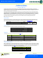
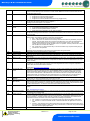
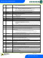
Mercury 3 M & E Installation Guide Network Configuration – IP comms Mercury 3 controllers with the IP interface as standard does not require any communications module and will already communicate on the IP network protocol. When networking the Ethernet variant, the ‘Net’ menu will have the following menus; Display IP-L / IP-r Id AtyP ESC Option Read/ Write Static IP address / Read Only DHCP IP address The 3 digit network address IP-r / IP-L selection Exit Menu Similar to the IP Futura / switch setup IP-L allows you to fix a static IP address into the controller and IP-r allows you to give each controller on the system a unique network number (using the Id). To firstly select between IP-L and IP-r navigate to ‘AtyP’. IP-r Once IP-r is selected the controller must be given a unique 3 digit ‘network address’ that no other device on the network has (note if logging on to a Data Manager, this will be the device ID). Once the ID has been set connect the controller to the IP network for it then to be given an IP address by the DHCP server. To view the IP address given, within the Net menu, navigate to ‘IP-r’. IP-L If IP-L has been selected from the ‘AtyP’ menu the IP address must be given to the controller by navigating to ‘IP-L’ within ‘Net’. The following menu’s will be available; Display Option IP-1 IP Address byte 1 IP-2 IP Address byte 2 IP-3 IP Address byte 3 IP-4 IP Address byte 4 nL Network Mask Length (see the network mask length table above) gt-1 Gateway Address byte 1 gt-2 Gateway Address byte 2 gt-3 Gateway Address byte 3 gt-4 Gateway Address byte 4 ESC Exit network menu. N.B. this option must be selected to save any changes made in this menu Once the IP address has been entered, the controller can be connected to the IP network. Warning Ensure that all power is switched off before installing or maintaining this product Revision 1.0 Page 21 of 29 www.resourcedm.com Please Note