1
M30220TF-PRB
Pod Probe for M30220 and M30221 Group MCUs
User's Manual
Rev.1.00
September 1, 2003
REJ10J0280-0100Z
• NQPACK, YQPACK and YQ-GUIDE are products of Tokyo Eletech Corporation.
Keep safety first in your circuit designs!
• Renesas Technology Corporation and Renesas Solutions Corporation put the maximum effort into making semiconductor products better
and more reliable, but there is always the possibility that trouble may occur with them. Trouble with semiconductors may lead to personal
injury, fire or property damage. Remember to give due consideration to safety when making your circuit designs, with appropriate
measures such as (i) placement of substitutive, auxiliary circuits, (ii) use of nonflammable material or (iii) prevention against any
malfunction or mishap.
Notes regarding these materials
• These materials are intended as a reference to assist our customers in the selection of the Renesas Technology product best suited to
the customer's application; they do not convey any license under any intellectual property rights, or any other rights, belonging to Renesas
Technology Corporation, Renesas Solutions Corporation or a third party.
• Renesas Technology Corporation and Renesas Solutions Corporation assume no responsibility for any damage, or infringement of any
third-party's rights, originating in the use of any product data, diagrams, charts, programs, algorithms, or circuit application examples
contained in these materials.
• All information contained in these materials, including product data, diagrams, charts, programs and algorithms represents information
on products at the time of publication of these materials, and are subject to change by Renesas Technology Corporation and Renesas
Solutions Corporation without notice due to product improvements or other reasons. It is therefore recommended that customers contact
Renesas Technology Corporation, Renesas Solutions Corporation or an authorized Renesas Technology product distributor for the latest
product information before purchasing a product listed herein. The information described here may contain technical inaccuracies or
typographical errors. Renesas Technology Corporation and Renesas Solutions Corporation assume no responsibility for any damage,
liability, or other loss rising from these inaccuracies or errors. Please also pay attention to information published by Renesas Technology
Corporation and Renesas Solutions Corporation by various means, including the Renesas home page (http://www.renesas.com).
• When using any or all of the information contained in these materials, including product data, diagrams, charts, programs, and algorithms,
please be sure to evaluate all information as a total system before making a final decision on the applicability of the information and
products. Renesas Technology Corporation and Renesas Solutions Corporation assume no responsibility for any damage, liability or
other loss resulting from the information contained herein.
• Renesas Technology semiconductors are not designed or manufactured for use in a device or system that is used under circumstances
in which human life is potentially at stake. Please contact Renesas Technology Corporation, Renesas Solutions Corporation or an
authorized Renesas Technology product distributor when considering the use of a product contained herein for any specific purposes,
such as apparatus or systems for transportation, vehicular, medical, aerospace, nuclear, or undersea repeater use.
• The prior written approval of Renesas Technology Corporation and Renesas Solutions Corporation is necessary to reprint or reproduce
in whole or in part these materials.
• If these products or technologies are subject to the Japanese export control restrictions, they must be exported under a license from the
Japanese government and cannot be imported into a country other than the approved destination. Any diversion or reexport contrary to
the export control laws and regulations of Japan and/or the country of destination is prohibited.
• Please contact Renesas Technology Corporation or Renesas Solutions Corporation for further details on these materials or the products
contained therein.
Precautions to be taken when using this product
• This product is a development supporting unit for use in your program development and evaluation stages. In mass-producing your
program you have finished developing, be sure to make a judgment on your own risk that it can be put to practical use by performing
integration test, evaluation, or some experiment else.
• In no event shall Renesas Solutions Corporation be liable for any consequence arising from the use of this product.
• Renesas Solutions Corporation strives to renovate or provide a workaround for product malfunction at some charge or without charge.
However, this does not necessarily mean that Renesas Solutions Corporation guarantees the renovation or the provision under any
circumstances.
• This product has been developed by assuming its use for program development and evaluation in laboratories. Therefore, it does not fall
under the application of Electrical Appliance and Material Safety Law and protection against electromagnetic interference when used in
Japan.
• This product is not qualified under UL or other safety standards and IEC or other industry standards. This fact must be taken into account
when taking this product from Japan to some other country.
For inquiries about the contents of this document or product, fill in the text file the installer of the emulator debugger generates in the
following directory and email to your local distributor.
\SUPPORT\Product-name\SUPPORT.TXT
Renesas Tools Homepage http://www.renesas.com/en/tools
( 2 / 54 )
Preface
The M30220TF-PRB is a pod probe for flash memory rewrite mode debug of the M30220 and
M30221 Group of Renesas 16-bit MCUs. The M30220TF-PRB is used by connecting to a PC4701
emulator main unit and the M30200T-RPD-E emulation pod main unit. This product can debug the
CPU rewrite mode.
CPU rewrite mode debug is a function for debugging rewrites of internal flash memory using your
application software. For details on specifications and writing conditions of CPU rewrite mode, refer
to the user's manual of M30220 Group MCUs.
This manual mainly explains specifications, how to set up the M30220TF-PRB and the debugging
procedure for CPU rewrite mode. For detail information about the emulator main unit, emulation pod
main unit, and emulator debugger, refer to each user's manual.
Emulator main unit:
Emulation pod main unit:
Emulator debugger:
PC4701 User's Manual
M30200T-RPD-E User's Manual
M3T-PD30 User's Manual
To check the components of this product, refer to "2.1 Package Components" (page 14) in this
manual. If there is any question or doubt about this product, contact your local distributor.
To use the product properly
Precautions for Safety:
• Both in this User's Manual and on the product itself, several icons are used to insure
proper handling of this product and also to prevent injuries to you or other persons,
or damage to your properties.
• The icons' graphic images and meanings are given in "Chapter 1. Precautions for
Safety". Be sure to read this chapter before using the product.
( 3 / 54 )
Contents
Terminology ........................................................................................................................... 6
Chapter 1. Precautions for Safety ........................................................................................... 7
1.1 Safety Symbols and Meanings .............................................................................. 8
Chapter 2. Preparation .......................................................................................................... 13
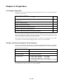
2.1 Package Components .......................................................................................... 14
2.2 Other Tool Products Required for Development ................................................ 14
2.3 System Configuration .......................................................................................... 15
Chapter 3. Setting Up ........................................................................................................... 17
3.1 Switch Settings .................................................................................................... 18
3.2 A-D Conversion Bypass Capacitor ..................................................................... 20
3.3 Connecting the M30200T-RPD-E ....................................................................... 21
3.4 Connecting the Target System ............................................................................ 22
3.5 Procedure for Making an MCU File for M3T-PD30 .......................................... 26
Chapter 4. Debugging Procedure for CPU Rewrite Mode ................................................... 27
4.1 Outline of Debugging Procedure ........................................................................ 28
4.2 Using Custom Commands dbg_reset and fmcr1set ............................................ 29
(1) Custom Command dbg_reset ................................................................... 29
(2) Custom Command fmcr1set ..................................................................... 30
4.3 Debugging Procedure .......................................................................................... 32
(1) Debugging Procedure for CPU Rewrite Mode (Microcomputer Mode) . 32
(2) Debugging Procedure for CPU Rewrite Mode (Boot Mode) ................... 34
4.4 How to Access Flash Memory Area ................................................................... 36
(1) Using Script Commands .......................................................................... 36
(2) Using the Dump Window ......................................................................... 36
(3) Using the RAM Monitor Window ........................................................... 36
4.5 Precautions for CPU Rewrite Mode .................................................................... 37
Chapter 5. Specifications ...................................................................................................... 41
5.1 Specifications ...................................................................................................... 42
5.2 External Dimensions ........................................................................................... 43
(1) External Dimensions of the Pod Probe .................................................... 43
(2) External Dimensions of the Converter Board (FLX-144NSD) ................ 43
(3) External Dimensions of the Converter Board (FLX-144NSE) ................ 44
(4) External Dimensions of the Converter Board (FLX-120NSE) ................ 44
( 4 / 54 )
Chapter 6. Troubleshooting .................................................................................................. 45
6.1 When the Emulator Debugger Does Not Start Up Properly ............................... 46
(1) When the LED Display of PC4701 is Abnormal ..................................... 46
(2) Errors Occur When Starting Up the Emulator Debugger
(When the target system is connected) .................................... 47
(3) Errors Occur When Starting Up the Emulator Debugger
(When the target system is not connected) .............................48
6.2 Operation Differs from That of Actual MCUs .................................................... 48
Chapter 7. Maintenance and Warranty ................................................................................. 49
7.1 Maintenance ........................................................................................................ 50
7.2 Warranty .............................................................................................................. 50
7.3 Repair Provisions ................................................................................................ 50
7.4 How to Request for Repair .................................................................................. 51
( 5 / 54 )
Terminology
Some specific words used in this user's manual are defined as follows:
Emulator system
This means an emulator system built around the PC4701 emulator. The PC4701 emulator system is
configured with an emulator main unit, emulation pod, pod probe, host machine and emulator
debugger.
Emulator main unit (Hereafter PC4701)
This means the generic name for emulators for 8 and 16-bit MCUs. For details on specific models
of PC4701, visit Renesas Tools Homepage at http://www.renesas.com/en/tools
Emulation pod main unit
This means the emulation pod M30200T-RPD-E for the M16C/20 Series MCUs.
Pod probe
This means pod probe M30220TF-PRB (this product) for the M30220 and M30221 Groups.
Host machine
This means a personal computer used to control the emulator and emulation pod.
Emulator debugger
This means a software tool M3T-PD30 to control the emulator from the host machine through an
interface.
Firmware
Program that analyzes contents of communication with the emulator debugger and controls the
emulator hardware. This program is installed in the EEPROM in the emulator main unit. This
program is downloadable from the emulator debugger to upgrade the firmware or to support other
MCUs.
Software break
A software break is a function to break the program before the system executes an instruction at the
specified address. The instruction at the preset address will not be executed.
Hardware break
A hardware break is a function to break the program when the system detects a write/read of data to/
from memory or a rise/fall edge of the signal entered from the external trace cable. The former break
function is called address break; and the latter break function is called trigger break. While the
instruction at the address where the software break is set is not executed, a hardware break is
performed after the specified instruction is executed.
Evaluation MCU
This means the MCU mounted on the pod probe which is operated in the specific mode for tools.
Target MCU
This means the MCU you are going to debug.
Target system
This means a user's application system using the MCU to be debugged.
*
In this user's manual, this symbol is used to show active LOW. (e.g. RESET*: Reset signal)
( 6 / 54 )
Chapter 1. Precautions for Safety
This chapter describes precautions for using this product safely and properly. For precautions for the emulator main unit,
the emulation pod main unit and the emulator debugger, refer to each user's manual included with your product.
1.1 Safety Symbols and Meanings ..................................................................................................... 8
IMPORTANT
Note on Final Evaluation ............................................................................................. 9
Note on Differences between Actual MCU and Emulator .......................................... 9
Note on Clock Supply to the MCU ............................................................................ 10
Notes on Interrupts ..................................................................................................... 10
Notes on DMA Transfer ............................................................................................ 10
Notes on NMI* Input ................................................................................................. 10
Notes on Referencing and Setting the Work Area ..................................................... 11
Notes on MAP References and Settings .................................................................... 11
Note on Reading SFR Area........................................................................................ 11
Note on Instructions that Access the Single-step Interrupt Vector Area ................... 11
Note on CPU Rewrite Mode ...................................................................................... 11
( 7 / 54 )
Chapter 1. Precautions for Safety
In both the user's manual and on the product itself, several icons are used to insure proper handling
of this product and also to prevent injuries to you or other persons, or damage to your properties.
This chapter describes the precautions which should be taken in order to use this product safely and
properly. Be sure to read this chapter before using this product.
1.1 Safety Symbols and Meanings
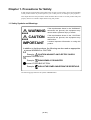
WARNING
If the requirements shown in the "WARNING"
sentences are ignored, the equipment may
cause serious personal injury or death.
CAUTION
If the requirements shown in the "CAUTION"
sentences are ignored, the equipment may
malfunction.
IMPORTANT
It means important information on using this
product.
In addition to the three above, the following are also used as appropriate.
means WARNING or CAUTION.
Example:
CAUTION AGAINST AN ELECTRIC SHOCK
means PROHIBITION.
Example:
DISASSEMBLY PROHIBITED
means A FORCIBLE ACTION.
Example:
UNPLUG THE POWER CABLE FROM THE RECEPTACLE.
The following pages describe the symbol "IMPORTANT".
( 8 / 54 )
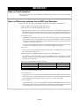
IMPORTANT
Note on Final Evaluation:
• Be sure to evaluate your system and make final confirmation with an CS (Commercial Sample)
version MCU.
Note on Differences between Actual MCU and Emulator:
• Operations of the emulator system differ from those of actual MCUs as listed below.
(1) Initial values of internal resource data at power-on
(2) Internal memories (ROM and RAM) capacities, etc.
With this emulator system, "INT" (emulation memory ON) is the default for mapping areas
other than the SFR area (addresses 000h - 3FFh). For this reason, the emulation memories can
be read and written into in an area other than the SFR, internal RAM or internal ROM area.
(3) Oscillator circuit
• Make note of the fact that in the oscillator circuit where an oscillator is connected between
the XIN and XOUT pins, oscillation does not occur because a flexible cable, buffer IC and other
devices are used between the evaluation MCU and the target system. It is same for sub-clock
oscillator circuits (XCIN and XCOUT ).
• For note on when using the oscillator circuit on the target system, refer to "4.2 (2) Using
target system's oscillator" (page 21) of the M30200T-RPD-E User's Manual.
(4) XOUT pin
The XOUT pin is not assigned to the evaluation MCU used by this product. For this reason, the
XOUT pin of this product is open.
(5) DBC, single-step and BRK instruction interrupt vector table addresses
It is possible to download to DBC, single-step and BRK instruction interrupt vector table
addresses. However, because the emulator system uses these areas, data different from the
expected value is read out.
Table 1.1 Vector table addresses for the emulator
Factor to interrupt
DBC*
Vector table addresses
1
Data for reading
FFFF4h - FFFF7h
Indefinite
Single-step*1
FFFECh - FFFEFh
Indefinite
BRK instruction*1
FFFE4h - FFFE7h
Indefinite
*1 Interrupts used for the debugger only
(6) A-D conversion
The characteristics of A-D converter differ from those of actual MCU because there are a
flexible cable, pitch converter and other devices between the evaluation MCU and the target
system. Make the final evaluation of the A-D converter with the actual MCU.
(7) D-A conversion
The characteristics of D-A converter differ from those of actual MCU because there are a
flexible cable, pitch converter and other devices between the evaluation MCU and the target
system. Make the final evaluation of the D-A converter with the actual MCU.
( 9 / 54 )
IMPORTANT
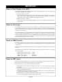
Note on Clock Supply to the MCU:
• Clock can be supplied to the evaluation MCU in one of the following two ways. This is determined
by emulator debugger clock selection.
(1) When "Internal" is selected:
The clock generated by the oscillation circuit in the emulation pod is supplied to the evaluation
MCU. The clock is continually supplied to the evaluation MCU regardless of "the state of
target system clock" and "the state of target program execution".
(2) When "External" is selected:
Clock supply to the evaluation MCU depends on the state of oscillation (oscillate/off) of the
target system.
Notes on Interrupts:
• Even while the target program is not being executed (i.e., even when the target program is paused
or while debug programs are running), the evaluation MCU is operating for controlling debug
programs. Therefore, take note that timers and other functions do not come to a halt when the target
program is not executed.
• If a maskable interrupt is requested while a target program is not being executed (when the target
program is paused or while debug programs are running), the interrupt is not accepted, because the
emulator disables maskable interrupts. If a maskable interrupt is requested while a target program
is not being executed and the program allow the interrupt, the interrupt is accepted immediately
after the target program execution is started.
Notes on DMA Transfer:
• If a DMA request occurs by a timer or other source when the target program is not being executed
(i.e., even when the target program is paused or while debug programs are running), DMA transfer
is executed.
• Make note of the fact that DMA transfer while the target program is stopped may not be performed
correctly.
• Note that the below registers are changed if DMA transfer is generated even when not executing
the target program.
DMA0 transfer counter register:
DMA1 transfer counter register:
DMA0 control register:
DMA1 control register:
TCR0
TCR1
DM0CON
DM1CON
Notes on NMI* Input:
• NMI* input from the target system is accepted only while a target program is being executed (i.e.,
only while the RUN status LED on the PC4701's front panel is lit).
• The NMI* interrupt is generated in the following situations.
(1) Immediately after the NMI* pin changes from "H" to "L" level during target program
execution
(2) Immediately after the reset from the target system is released with the NMI* pin "L" level
during target program execution
(3) Immediately after program execution starts with the NMI* pin "L" level, following the reset
is input from the debugger software or emulator
(4) Immediately after program execution starts with the NMI* pin "L" level, when the NMI* pin
is "H" level immediately before the target program stops
( 10 / 54 )
IMPORTANT
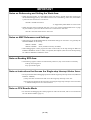
Notes on Referencing and Setting the Work Area:
• When using this product, set a start address of the work area to "2C00h" at the time of starting up
the emulator debugger (set by "F/W and Work Area" tab*1 of Init dialog). In this case, the emulator
system uses the area below as a work area.
02C00h - 02C0Fh: Work area
*1 Supported by M3T-PD30 Ver.4.00 or later
• When using the custom command "fmcr1set" (see "4.2 (2) Custom Command fmcr1set" on page
30), the emulator system uses the area below as a work area for "fmcr1set".
02C10h - 02C1Ah: Work area for "fmcr1set"
Notes on MAP References and Settings:
• When starting up the M30200T-RPD-E, initial MAP settings are as follows. Use generally the
M30200T-RPD-E in this setting.
00000h - 003FFh:
00400h - FFFFFh:
"EXT"
"INT" (emulation memory available)
• When debugging the control program for CPU rewrite mode, set the map setting for addresses
E0000h to FFFDFh to "EXT" or "INT", as required. (See Chapter 4.) Be sure to set the map setting
for addresses FFFE0h to FFFFFh to "INT".
Note on Reading SFR Area:
• The following registers cannot be read normally. However, they can be written to normally.
Pull-up control register 2
Key input mode register
Note on Instructions that Access the Single-step Interrupt Vector Area:
• Do not perform the below debugging operations with the single step interrupt vector area (addresses
FFFECh - FFFEFh).
(1) Step execution of instructions that access the single step interrupt vector area
(2) Program execution from the instruction accessing the single step interrupt vector area when
a software breakpoint is set at the instruction
Note on CPU Rewrite Mode:
• For the notes for debugging the control program for CPU rewrite mode, refer to "4.5 Precautions
for CPU Rewrite Mode" (page 37).
( 11 / 54 )
MEMO
( 12 / 54 )
Chapter 2. Preparation
This chapter describes the package components, the system configuration and the preparation for using this product for the
first time.
2.1 Package Components.................................................................................................................. 14
2.2 Other Tool Products Required for Development........................................................................ 14
2.3 System Configuration ................................................................................................................. 15
( 13 / 54 )
Chapter 2. Preparation
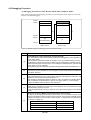
2.1 Package Components
This product consists of the following items. When unpacking, check to see if your product package
contains all of these items.
Table 2.1 Package components
Item
Quantity
M30220TF-PRB pod probe for flash memory rewrite mode debug of M30220 and M30221
Group MCUs
1
Screws for fixing pod probe
2
Floppy disk (custom program file)
1
M30220TF-PRB User's Manual (this manual)
1
M30220TF-PRB User's Manual (Japanese)
1
M30220TF-PRB Repair Request Sheet (English/Japanese)
1
Please keep the M30220TF-PRB's packing box and cushion material in your place for reuse at a later
time when sending your product for repair or other purposes. Always use these packing box and
cushion material when transporting the M30220TF-PRB.
If any of these items are missing or found faulty, please contact your local distributor. Also, if there
is any question or doubt about the packaged product, contact your local distributor.
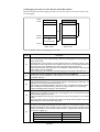
2.2 Other Tool Products Required for Development
To bring forward programs development on the M30220 and M30221 Group MCUs, the products
listed below are necessary in addition to the package components listed above. Get them separately.
Table 2.2 Other tool products
Emulator main unit
PC4701
Emulation pod main unit
M30200T-RPD-E
Emulator debugger
M3T-PD30 Ver.4.00 or later
Converter board
For 144-pin LQFP (144P6Q-A):
FLX-144NSD
For 144-pin TQFP (144PFB-A):
FLX-144NSE
For 120-pin LQFP (120P6R-A):
FLX-120NSE
The converter board which matches to the foot pattern of the target
system is required.
To purchase these products, contact your nearest distributer.
( 14 / 54 )
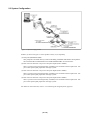
2.3 System Configuration
Figure 2.1 System configuration
Product (1) shown in Figure 2.1 is this product. Get (2) to (4) separately.
(1) Pod probe (M30220TF-PRB)
This pod probe is for flash memory rewrite mode debug of M30220 and M30221 Group MCUs.
The evaluation MCUs M30220GP-EVA and M30220GP-PORT are mounted on it.
(2) Pitch converter board for 144-pin 0.5-mm-pitch LQFP (FLX-144NSD)
This is a pitch converter board (separately available) to be mounted on the foot pattern for 144pin 0.5-mm-pitch LQFP prepared on the target system.
(3) Pitch converter board for 144-pin 0.4-mm-pitch TQFP (FLX-144NSE)
This is a pitch converter board (separately available) to be mounted on the foot pattern for 144pin 0.4-mm-pitch TQFP prepared on the target system.
(4) Pitch converter board for 120-pin 0.4-mm-pitch LQFP (FLX-120NSE)
This is a pitch converter board (separately available) to be mounted on the foot pattern for 120pin 0.4-mm-pitch LQFP prepared on the target system.
For details on the connection, refer to "3.4 Connecting the Target System" (page 22).
( 15 / 54 )
MEMO
( 16 / 54 )
Chapter 3. Setting Up
This chapter describes switch settings required for using this product and how to connect this product to the PC4701 and
the target system.
3.1 Switch Settings ........................................................................................................................... 18
3.2 A-D Conversion Bypass Capacitor ............................................................................................ 20
3.3 Connecting the M30200T-RPD-E .............................................................................................. 21
3.4 Connecting the Target System.................................................................................................... 22
3.5 Procedure for Making an MCU File for M3T-PD30.................................................................. 26
( 17 / 54 )
Chapter 3. Setting Up
With this product, it is necessary to set the following according to your target system.
• CNVSS pin to the target system
• XCIN/XCOUT pin to the target system
• Mounting the A-D conversion bypass capacitor
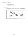
3.1 Switch Settings
It is necessary to set the switches of the M30220TF-PRB and FLX64-PRB for debugging according
to the target system. Figure 3.1 shows the positions of the switches of the M30220TF-PRB and
FLX64-PRB, and Table 3.1 shows the switch settings.
Figure 3.1 Positions of the switches and their factory-settings
( 18 / 54 )
Table 3.1 Switch settings of the M30220TF-PRB and FLX64-PRB
Board
Switch No.
Switch setting
Function
VDD
M30220TF-PRB
JP1
JP1
CNVSS
XCIN
CNVSS
CNVSS
When connecting CNVSS
to the target system
(Factory-setting)
Applies the VCC voltage to
CNVSS. When not
connecting the target,
applies 5 V.
The M30220TF-PRB does not use this switch.
XCIN is always selected in any setting.
FLX64-PRB
PORT
JP2
VDD
PORT
XCOUT
NC
NC
When connecting XCOUT to
the target system
(Factory-setting)
When not connecting
XCOUT to the target system
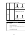
IMPORTANT
Note on CNVSS:
• To debug the control program for CPU rewrite mode, you need to apply 4.5 to 5.5
V voltage to the CNVSS pin.
When the target system is connected:
Set the jumper switch JP1 of the M30220TF-PRB to "CNVSS". The CNVSS is
connected to the target system. Apply 4.5V to 5.5V voltage to the CNVSS pin of the
target system.
When the target system is NOT connected:
Set the jumper switch JP1 of the M30220TF-PRB to "VDD". 5V voltage is applied
from the emulation pod to the CNVSS.
( 19 / 54 )
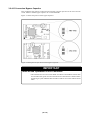
3.2 A-D Conversion Bypass Capacitor
This product has foot patterns on the board for mounting a bypass capacitor for the A-D converter
circuit. Mount a suitable bypass capacitor as occasion demands.
Figure 3.2 shows the position of the bypass capacitor.
Figure 3.2 Foot patterns of A-D conversion bypass capacitor
IMPORTANT
Note on the Operation of A-D Converter:
• The characteristics of A-D converter differ from those of actual MCU because there
are a flexible cable, pitch converter and other devices between the evaluation MCU
and the target system. Make the final evaluation of the A-D converter with the actual
MCU.
( 20 / 54 )
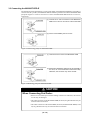
3.3 Connecting the M30200T-RPD-E
The emulation pod for flash memory rewrite mode debug of the M30220 and M30221 Group MCUs
consists of the two products, the M30200T-RPD-E emulation pod main unit and the M30220TF-PRB
pod probe. Figures 3.3 and 3.4 show how to connect the M30220TF-PRB and how to remove it,
respectively.
(1) Connect the J1 and J2 connectors of the M30220TFPRB to the J3 and J4 connectors of the FLX64-PRB.
(2) Fix the FLX64-PRB by the two screws.
Figure 3.3 Connecting pod probe M30220TF-PRB
(1) Unscrew the two screws of the M30220TF-PRB.
(2) Remove the M30220TF-PRB from the FLX64-PRB. In
this time, lift off the M30220TF-PRB horizontally.
Otherwise, the connector may cause a break.
Figure 3.4 Removing pod probe M30220TF-PRB
CAUTION
When Connecting Pod Probe:
• Be sure to turn off the power before making connections. Otherwise, the internal
circuits may be damaged.
• The small connectors of the M30220TF-PRB (J3 and J4) are guaranteed for only 50
insertion/removal iterations.
• The small connectors of the FLX64-PRB (J3 and J4) and M30220TF-PRB (J1 and
J2) are guaranteed for only 50 insertion/removal iterations.
( 21 / 54 )
3.4 Connecting the Target System
There are three ways available to connect this product to target system as shown in Figure 3.5.
Figure 3.5 Connecting the target system
( 22 / 54 )
Figures 3.6, 3.7 and 3.8 show how to connect the pitch converter board FLX-144NSD for 144-pin
0.5-mm-pitch package, how to connect the pitch converter board FLX-144NSE for 144-pin 0.4-mmpitch package and how to connect the pitch converter board FLX-120NSE for 120-pin 0.4-mm-pitch
package, respectively.
(1) Mount the NQPACK144SD included in the FLX144NSD (separately available) to the target system.
(2) Connect the YQPACK144SD included in the FLX144NSD to the NQPACK144SD. Secure the
YQPACK144SD using the YQ-GUIDE's.
(3) Connect the FLX-144NSD to the M30220TF-PRB.
(4) Connect the FLX-144NSD to the YQPACK144SD.
Figure 3.6 Connecting the pitch converter board FLX-144NSD for 144-pin 0.5-mm-pitch LQFP
CAUTION
Note on Connecting the Target System:
• Take care not to mount the pitch converter board in a wrong direction.
( 23 / 54 )
(1) Mount the NQPACK144SE included in the FLX144NSE (separately available) to the target system.
(2) Connect the YQPACK144SE included in the FLX144NSE to the NQPACK144SE. Secure the
YQPACK144SE using the YQ-GUIDE's.
(3) Connect the FLX-144NSE to the M30220TF-PRB.
(4) Connect the FLX-144NSE to the YQPACK144SE.
Figure 3.7 Connecting the pitch converter board FLX-144NSE for 144-pin 0.4-mm-pitch TQFP
CAUTION
Note on Connecting the Target System:
• Take care not to mount the pitch converter board in a wrong direction.
( 24 / 54 )
(1) Mount the NQPACK120SE included in the FLX120NSE (separately available) to the target system.
(2) Connect the YQPACK120SE included in the FLX120NSE to the NQPACK120SE. Secure the
YQPACK120SE using the YQ-GUIDE's.
(3) Connect the FLX-120NSE to the M30220TF-PRB.
(4) Connect the FLX-120NSE to the YQPACK120SE.
Figure 3.8 Connecting the pitch converter board FLX-120NSE for 120-pin 0.4-mm-pitch LQFP
CAUTION
Note on Connecting the Target System:
• Take care not to mount the pitch converter board in a wrong direction.
( 25 / 54 )
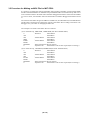
3.5 Procedure for Making an MCU File for M3T-PD30
It is necessary to change the contents of the MCU file according to the MCU to be developed. Make
the MCU file M30220.MCU for M30220 Group and M30221.MCU for M30221 Group and store it
in the "mcufiles" folder in the folder where emulator debugger M3T-PD30 is stored. For M3T-PD30
Ver.4.10 or earlier, store the MCU file in the same folder as emulator debugger M3T-PD30 is stored
in.
The contents of the MCU file give the addresses of SFR area, internal RAM area, internal ROM area
and the name of firmware file. Change the contents of the MCU file according to the MCU to be
debugged. Use your editor for changing the MCU file.
The examples of contents of the MCU file are as follows:
(1) For 30220 Group, 10KB RAM, 128KB ROM (file name: M30220.MCU)
0
3FF
400
2BFF
E0000
FFFFF
M30620B
0
: SFR area
Start address
:
End address
: Internal RAM
Start address
:
End address
: Internal ROM
Start address
:
End address
: Name of firmware (Do not change.)
: Expansion No.
M3T-PD30 V.4.00 or later required (Do not change.)
(2) For 30221 Group, 1.5KB RAM, 24KB ROM (file name: M30221.MCU)
0
3FF
400
9FF
FA000
FFFFF
M30620B
0
: SFR area
Start address
:
End address
: Internal RAM
Start address
:
End address
: Internal ROM
Start address
:
End address
: Name of firmware (Do not change.)
: Expansion No.
M3T-PD30 V.4.00 or later required (Do not change.)
( 26 / 54 )
Chapter 4. Debugging Procedure for CPU Rewrite Mode
This chapter describes procedure for debugging the control program for CPU rewrite mode and restrictions.
4.1 Outline of Debugging Procedure ................................................................................................ 28
4.2 Using Custom Commands dbg_reset and fmcr1set.................................................................... 29
(1) Custom Command dbg_reset ................................................................................................ 29
(2) Custom Command fmcr1set ................................................................................................. 30
4.3 Debugging Procedure ................................................................................................................. 32
(1) Debugging Procedure for CPU Rewrite Mode (Microcomputer Mode) .............................. 32
(2) Debugging Procedure for CPU Rewrite Mode (Boot Mode) ............................................... 34
4.4 How to Access Flash Memory Area ........................................................................................... 36
(1) Using Script Commands ....................................................................................................... 36
(2) Using the Dump Window ..................................................................................................... 36
(3) Using the RAM Monitor Window ........................................................................................ 36
4.5 Precautions for CPU Rewrite Mode ............................................................................................ 37
Note on Custom Command dbg_reset ........................................................................................ 37
Note on CNVSS ......................................................................................................................... 37
Note on Address E0000h - FFFDFh Memory ............................................................................ 37
Note on Boot Mode .................................................................................................................... 37
Notes on Setting Software Breaks .............................................................................................. 38
Note on RESET from the Target System ................................................................................... 38
Note on Setting the CPU Rewrite Mode Select Bit .................................................................... 38
Note on Address FFFE0h - FFFFFh ........................................................................................... 38
Note on Changing the Mode of Flash Memory .......................................................................... 38
Note on Step Execution .............................................................................................................. 38
Note on Number of Program/Erase ............................................................................................ 39
Note on Shutting OFF the Power ............................................................................................... 39
( 27 / 54 )
Chapter 4. Debugging Procedure for CPU Rewrite Mode
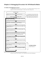
4.1 Outline of Debugging Procedure
You can use the flash memory in the evaluation MCU on the M30220TF-PRB to debug the control
program for CPU rewrite mode. Figure 4.1 shows a flow chart of the process.
Start M3T-PD30.
Register custom commands dbg_reset and fmcr1set.
Execute custom command dbg_reset.
<- Once registered in the M3T-PD30, there
is no need to register again. (See section
4.2.)
<- This command must be executed once
at M3T-PD30 startup. (See section 4.2.)
Execute the script command "MAP E0000, FFFDF, INT".
(emulation memory enabled)
Download the control program for CPU rewrite mode into the user
ROM area or boot ROM area (emulation memory).
Set a breakpoint so that the program can be stopped after
jumping to the RAM area, and before the CPU rewrite mode
select bit is set to "1".
Run the control program and transfer the rewrite program to the
RAM area (emulation memory).
Stop the control program using the preset breakpoint immediately
before the CPU rewrite mode select bit is set to "1" and when the
program counter (PC) value is in the internal RAM area.
Set a breakpoint so that the program stops immediately before
jumping to the user ROM area.
Execute the script command "MAP E0000, FFFDF, EXT". (MCU
enabled)
Execute the rewrite program to set the CPU rewrite mode select
bit to "1" (MCU's internal flash memory enabled), and rewrite to
the flash memory.
Using the preset breakpoint, stop the control program immediately
before jumping to the user ROM area (addresses E0000h to
FFFFFh).
Debugging is enabled in
CPU rewrite mode. See
notes in section 4.5.
Figure 4.1 Flowchart of CPU Rewrite Mode Control Program Debugging
The process shown in this flowchart is not required for normal program debugging.
( 28 / 54 )
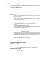
4.2 Using Custom Commands dbg_reset and fmcr1set
The custom commands dbg_reset and fmcr1set must be used when debugging in CPU rewrite mode.
The custom command program file is provided on the attached floppy disk.
(1) Custom Command dbg_reset
When debugging in CPU rewrite mode, you must execute custom command dbg_reset to initialize
tool control.
To use custom command dbg_reset, use the following procedure to register dbg_reset in the M3TPD30. Once registered, dbg_reset can be used without the need to reregister it each time.
How to register dbg_reset with M3T-PD30
Step 1:
Copy file.
Copy dbg_reset.p (program file of custom command dbg_reset) from the attached floppy
disk to the host machine.
Example 1:
Copy dbg_reset.p to the folder (e.g. C:¥MTOOL¥M3T-PD30) containing the executable
file of M3T-PD30 (M3T-PD30.exe).
Step 2:
Set the search path of the custom program.
Open the M3T-PD30 script window and execute the following script command:
MacroPATH "absolute directory to which dbg_reset.p was copied"
Example 1:
MacroPATH C:¥MTOOL¥M3T-PD30 <RET>
The MacroPATH command is the script command to set the path specified in the argument
as the path to the custom program in M3T-PD30.
Step 3:
Register custom command dbg_reset.
Execute the following script command in the M3T-PD30 script window:
MACRO dbg_reset <RET>
The MACRO command is the script command to register the custom command specified
in the argument in M3T-PD30. This completes registration of custom command dbg_reset
in M3T-PD30. Custom command dbg_reset can now be executed from the script window
command input area in the same way as script commands. See the specifications for the
custom command (shown below) for the input format, etc. Note that once the custom
command has been registered, the registration remains valid until deleted using the
DELMACRO or DELMACROALL script command.
Step 4:
Restart M3T-PD30.
After completing steps 1 to 3, restart M3T-PD30. To use the custom command dbg_reset,
make sure that the search path is the absolute directory to which dbg_reset.p was copied.
Custom command dbg_reset specifications
Input format:
dbg_reset
Function:
Initializes and resets tool control for debugging in CPU rewrite mode.
(Note)
• This command cannot be used while the target program is running.
Command execution example
Example 1:
dbg_reset must be executed after starting M3T-PD30 if you are debugging in
CPU rewrite mode.
> dbg_reset <RET>
DBG_RESET is done !!
>
( 29 / 54 )
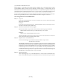
(2) Custom Command fmcr1set
When setting "1" in the CPU rewrite mode select bit (FMCR1) (bit 1 of the flash memory control
register (address 3B4h), you must write "0" followed consecutively by "1". Because of the interval
between the execution of two normal script commands, it is not possible using these normal script
commands to write "0" followed consecutively by "1". You can set "1" by using the custom command
fmcr1set, which consecutively writes "0", "1" to the CPU rewrite mode select bit (FMCR1).
To use custom command fmcr1set, use the following procedure to register fmcr1set in the M3TPD30. Once registered, fmcr1set can be used without the need to reregister it each time.
How to register fmcr1set with M3T-PD30
Step 1:
Copy file.
Copy fmcr1set.p (program file of custom command fmcr1set) from the attached floppy
disk to the host machine.
Example 1:
Copy fmcr1set.p to the directory (e.g. C:¥MTOOL¥M3T-PD30) containing the executable file of M3T-PD30 (M3T-PD30.exe).
Step 2:
Set the search path of the custom program.
Open the M3T-PD30 script window and execute the following script command:
MacroPATH "absolute directory to which fmcr1set.p was copied"
Example 1:
MacroPATH C:¥MTOOL¥M3T-PD30 <RET>
The MacroPATH command is the script command to set the path specified in the argument
as the path to the custom program in M3T-PD30.
Step 3:
Register custom command fmcr1set.
Execute the following script command in the M3T-PD30 script window:
MACRO fmcr1set <RET>
The MACRO command is the script command to register the custom command specified
in the argument in M3T-PD30. This completes registration of custom command fmcr1set
in M3T-PD30. Custom command fmcr1set can now be executed from the script window
command input area in the same way as script commands. See the specifications for the
custom command (shown below) for the input format, etc. Note that once the custom
command has been registered, the registration remains valid until deleted using the
DELMACRO or DELMACROALL script command.
Step 4:
Restart M3T-PD30.
After completing steps 1 to 3, restart M3T-PD30. To use the custom command fmcr1set,
make sure that the search path is the absolute directory to which fmcr1set.p was copied.
( 30 / 54 )
Custom command fmcr1set specifications
Input format:
fmcr1set
Function:
fmcr1set writes the instruction to write "0" and the instruction to write "1" to
the CPU rewrite mode select bit (FMCR1) at addresses 2C10h to 2C1Ah,
executes them, then sets back the program counter (PC). The program window
display starts at the address set in the program counter (PC).
(Notes)
• The fmcr1set command can set "1" in the CPU rewrite mode select bit
(FMCR1).
• This command cannot be used while the target program is running.
• When the PC is where there is no source file, the program window is
displayed in Dis Assemble Mode and the PC line may be displayed in black.
If displayed in black, it indicates that the line is selected. Select another line
so that the PC line is displayed in yellow.
Command execution example
Example 1:
To set "1" in the CPU rewrite mode select bit (FMCR1).
> fmcr1set <RET>
FMCR1SET is done !!
>
( 31 / 54 )
4.3 Debugging Procedure
(1) Debugging Procedure for CPU Rewrite Mode (Microcomputer Mode)
Here following describe the debugging procedure in microcomputer mode. Figure 4.2 shows the
memory map when debugging.
00000h
00400h
SFR area
Unused
RAM area
(3)
(4)
DE000h
(2)
Boot ROM area
E0000h
(5)
User ROM area
(1)
Inside of MCU
(MAP: "EXT")
Emulation memory
(MAP: "INT")
FFFFFh
Figure 4.2 Memory map when debugging in microcomputer mode
Procedure
Description
(1)
Downloading the control program for CPU rewrite mode
• You must execute custom command dbg_reset before debugging the control program for
CPU rewrite mode.
• Set the MAP for addresses E0000h to FFFDFh to "INT" (to enable emulation memory).
• Download the control program for CPU rewrite mode to be debugged to emulation memory.
• After downloading the control program, set a breakpoint as indicated below. (See the next
page, Table 4.1 for an example.)
"Stop after jumping to the RAM area, and before setting the CPU rewrite mode select bit to "1"."
(2)
Transfer the control program for CPU rewrite mode to the RAM area.
• Running the program transfers the control program for CPU rewrite mode to the RAM area
(emulation memory).
(3)
Set the map for user ROM area E0000h to FFFDFh to "EXT".
• Using the breakpoint set in (1), stop program execution after jumping to RAM area, and
before the CPU rewrite mode select bit is set to "1".
• Set the MAP for addresses E0000h to FFFDFh to "EXT" (to enable the evaluation MCU).
• Set a breakpoint as indicated below. (See the next page, Table 4.1 for an example).
"Stop immediately before jumping to user ROM area."
(4)
Write to flash memory.
• Flash memory is rewritten to by running the control program. See "4.5 Precautions for CPU
Rewrite Mode" (page 37) for notes.
• Using the breakpoint set in step (3), stop at the end of the control program for CPU rewrite
mode.
Check the contents of MCU's internal flash memory after rewriting.
• In step (4), by changing the settings as shown below, you can read the contents of the
MCU's internal flash memory using the script command, dump window and RAM monitor
window. For details on how to access, refer to Section 4.4 (page 36) and the precautions
to Section 4.5 (page 37).
(5)
Item
Setting
Map of addresses E0000h - FFFDFh
EXT
CPU rewrite mode select bit (FMCR1)
1
Mode of flash memory
Read array mode
( 32 / 54 )
Table 4.1 lists how to set breakpoints for procedures 1 and 3.
Table 4.1 How to set breakpoints for procedures 1 and 3
Procedure
Description
• Examples 1 and 2 show how to set breakpoints to have the result shown below.
"Stop after jumping to the RAM area, and before setting the CPU rewrite mode select bit to "1"."
Example 1:
1
Example 2:
Set a software break at the instruction to jump to the RAM area. After
stopping, set the program window to disassemble display mode and step
execute the jump to the RAM area. This allows you to stop in the RAM area.
If there are 10 or more cycles after jumping to the RAM area and before the
instruction to access the CPU rewrite mode select bit, set a hardware break
to the RAM area Fetch.
• Examples 1, 2, and 3 show how to set breakpoints to have the result shown below:
"Stop immediately before jumping to user ROM area."
Example 1:
3
Example 2:
Example 3:
A jump to the user ROM area is made at the end of the control program
written to RAM. Set a software break at the jump instruction.
Set a software break in the instruction to set "0" in the CPU rewrite mode
select bit.
If there are enough cycles between the instruction to set "0" in the CPU
rewrite mode select bit and the instruction to jump to the user ROM area,
set a hardware break to the Write access to the flash memory control
register (address 3B4h).
CAUTION
Note on Address E0000h - FFFDFh Memory:
• When both the MAP setting for addresses E0000h to FFFDFh is "INT" and the
FMCR1 is set to "1", both the emulation memory and the MCU's internal flash
memory are enabled and bus collisions occur. Please avoid combining these settings.
Table 4.2 Address E0000h - FFFDFh memory
Map setting
FMCR1 setting
Remarks
INT
1
Do not set in this way.
( 33 / 54 )
(2) Debugging Procedure for CPU Rewrite Mode (Boot Mode)
Here following describe the debugging procedure in boot mode. Figure 4.3 shows the memory map
when debugging.
00000h
00400h
SFR area
Unused
RAM area
(3)
(4)
DE000h
(2)
(1)
Boot ROM area
E0000h
(5)
User ROM area
FFFFFh
Inside of MCU
(MAP: "EXT")
Emulation memory
(MAP: "INT")
Figure 4.3 Memory map when debugging in boot mode
Procedure
Description
(1)
Downloading the control program for CPU rewrite mode
• You must execute custom command dbg_reset before debugging the control program for
CPU rewrite mode.
• Download the control program for CPU rewrite mode into emulation memory. Also,
download the value of the reset vector, DE000h. When you do not download the value of
the reset vector, write "DE000h" in the reset vector area using Fill command.
• After downloading the control program, set a breakpoint as indicated below. (See the next
page, Table 4.3 for an example.)
"Stop after jumping to the RAM area, and before setting the CPU rewrite mode select bit to "1"."
(2)
Transfer the control program for CPU rewrite mode to the RAM area.
• Running the program transfers the control program for CPU rewrite mode to the RAM area
(emulation memory).
(3)
Set the map for user ROM area E0000h to FFFDFh to "EXT".
• Using the breakpoint set in (1), stop program execution after jumping to RAM area, and
before the CPU rewrite mode select bit is set to "1".
• Set the MAP for addresses E0000h to FFFDFh to "EXT" (to enable the evaluation MCU).
• Set a breakpoint as indicated below. (See the next page, Table 4.3 for an example).
"Stop immediately before jumping to user ROM area."
(4)
Write to flash memory.
• Flash memory is rewritten to by running the control program. See "4.5 Precautions for CPU
Rewrite Mode" (page 37) for notes.
• Using the breakpoint set in step (3), stop at the end of the control program for CPU rewrite
mode.
• Set the program window to disassemble display mode (DIS) and execute the instruction
that jumps to the user ROM area in step mode.
Check the contents of MCU's internal flash memory after rewriting.
• In step (4), by changing the settings as shown below, you can read the contents of the
MCU's internal flash memory using the script command, dump window and RAM monitor
window. For details on how to access, refer to Section 4.4 (page 36) and the precautions
to Section 4.5 (page 37).
(5)
Item
Setting
Map of addresses E0000h - FFFDFh
EXT
CPU rewrite mode select bit (FMCR1)
1
Mode of flash memory
Read array mode
( 34 / 54 )
Table 4.3 lists how to set breakpoints for procedures 1 and 3.
Table 4.3 How to set breakpoints for procedures 1 and 3
Procedure
Description
• Examples 1 and 2 show how to set breakpoints to have the result shown below.
"Stop after jumping to the RAM area, and before setting the CPU rewrite mode select bit to "1"."
Example 1:
1
Example 2:
Set a software break at the instruction to jump to the RAM area. After
stopping, set the program window to disassemble display mode and step
execute the jump to the RAM area. This allows you to stop in the RAM area.
If there are 10 or more cycles after jumping to the RAM area and before the
instruction to access the CPU rewrite mode select bit, set a hardware break
to the RAM area Fetch.
• Examples 1, 2, and 3 show how to set breakpoints to have the result shown below:
"Stop immediately before jumping to user ROM area."
Example 1:
3
Example 2:
Example 3:
A jump to the user ROM area is made at the end of the control program
written to RAM. Set a software break at the jump instruction.
Set a software break in the instruction to set "0" in the CPU rewrite mode
select bit.
If there are enough cycles between the instruction to set "0" in the CPU
rewrite mode select bit and the instruction to jump to the user ROM area,
set a hardware break to the Write access to the flash memory control
register (address 3B4h).
CAUTION
Note on Address E0000h - FFFDFh Memory:
• When both the MAP setting for addresses E0000h to FFFDFh is "INT" and the
FMCR1 is set to "1", both the emulation memory and the MCU's internal flash
memory are enabled and bus collisions occur. Please avoid combining these settings.
Table 4.4 Address E0000h - FFFDFh memory
Map setting
FMCR1 setting
Remarks
INT
1
Do not set in this way.
( 35 / 54 )
4.4 How to Access Flash Memory Area
When flash memory is enabled (MAP setting for addresses E0000h to FFFDFh is "EXT" and CPU
rewrite mode select bit is "1"), you must invoke software commands to access flash memory area.
The following shows how to access the flash memory area using script commands, the dump window,
and the RAM monitor window.
(1) Using Script Commands
To execute Fill and Dump commands to the flash memory area, you need to issue software
commands. When flash memory is enabled, software commands can be used. You can use the
FillWord or setMemoryWord commands to write software command code to the user ROM area. In
the read array mode or the read status register mode, the DumpWord command allows you to read
values from flash memory or status register, respectively.
Example 1:
To read values from flash memory
If you want to read a value from flash memory, you must first select the read array
mode. Use the FillWord or setMemoryWord command to write the read array
command (FFh) to the user ROM area. In the read array mode, the DumpWord
command allows you to read values from flash memory.
Example 2:
To rewrite data to flash memory
If you want to rewrite data to flash memory, use the FillWord or setMemoryWord
command to write the program command (40h) to the user ROM area, then write the
data to the address to be programmed. Note that, because you are in the read status
register mode, to check that the data has been written, first invoke the read array
command, as in Example 1, then read the data.
If the data was not FFFFh prior to being programmed, the data after being programmed
may differ from the data that was written. The post-programming data is the AND
value of the pre-programming data and the data that was written.
Example 3:
To block-erase flash memory
If you want to block-erase flash memory, use the FillWord or setMemoryWord
command to write 20h to the user ROM area, then write D0h to the address of the block
to be erased. Note that, because you are in read status register mode, to check that the
data has been erased, first invoke the read array command, as in Example 1, then read
the data.
(2) Using the Dump Window
When flash memory is enabled, the values of flash memory or status register are displayed in the read
array mode or the read status register mode, respectively. Take note that after writing to or erasing
flash memory, the values of the status register is displayed in the read status register mode.
If flash memory is enabled, software commands are valid and the procedure for invoking the software
commands can be performed in the dump window. If the FillWord or setMemoryWord command is
used from the dump window as in (1) above to perform a write operation, you can change the mode
of flash memory and program and erase flash memory via the dump window.
(3) Using the RAM Monitor Window
When flash memory is enabled, the values of flash memory or status register are displayed in the read
array mode or the read status register mode, respectively. (If you have changed mode, press the
"Clear" button to update the data display, which is not updated automatically when you change
modes.) See (1) and (2) above for details of how to select the read array mode and the read status
register mode.
( 36 / 54 )
4.5 Precautions for CPU Rewrite Mode
Here following are precautions and restrictions for debugging the control program for CPU rewrite mode.
IMPORTANT
Note on Custom Command dbg_reset:
• To debug the control program for CPU rewrite mode, you must execute the custom
command dbg_reset once every time you start emulator debugger M3T-PD30.
If you set the MAP setting of addresses E0000h to FFFDFh to "EXT" without
executing dbg_reset, the emulator will run out of control.
Note on CNVSS:
• To debug the control program for CPU rewrite mode, you need to apply 4.5 to 5.5
V voltage to the CNVSS pin.
When the target system is connected:
Set the jumper switch JP1 of the M30220TF-PRB to "CNVSS". The CNVSS is
connected to the target system. Apply 4.5V to 5.5V voltage to the CNVSS pin of the
target system.
When the target system is NOT connected:
Set the jumper switch JP1 of the M30220TF-PRB to "VDD". 5V voltage is applied
from the emulation pod to the CNVSS.
Note on Address E0000h - FFFDFh Memory:
• Table 4.5 shows the areas of memory addresses E0000h to FFFDFh that are enabled
according to the MAP setting and the value of the CPU rewrite mode select bit
(FMCR1).
Table 4.5 Memory addresses E0000h to FFFDFh
Map setting
FMCR1 setting
0
INT
EXT
Valid area
Remarks
Emulation memory
1
-
0
No valid area
1
MCU's internal flash memory
Forbidden*1
*1. When both the MAP setting for addresses E0000h to FFFDFh is "INT" and the
FMCR1 is set to "1", both the emulation memory and the MCU's internal flash
memory are enabled and bus collisions can occur. Please avoid combining these
settings.
When both the MAP setting for addresses E0000h to FFFDFh is "EXT" and the
FMCR1 is set to "0", no memory area is enabled and undefined values will be read.
Note on Boot Mode:
• Even when the P74 (CE) pin is "H" and the CNVSS pin is "H", boot mode cannot
be selected when the reset is released.
If you want to debug the control program for CPU rewrite mode using operations as
in boot mode, download DE000h to the reset vector area as well as the control
program. If you do not download the reset vector, use script commands, etc., to write
DE000h to the reset vector area.
( 37 / 54 )
IMPORTANT
Notes on Setting Software Breaks:
• When setting software breaks in the control program for CPU rewrite mode
transferred to the RAM area, set the software break points after making the transfer.
The software breaks will not function if you set them before the program is
transferred to the RAM area.
• When setting "1" in the CPU rewrite mode select bit, you must write "0" followed
consecutively by "1". When a software break is set to the instruction to write "0", you
will not be able to set "1" in the CPU rewrite mode select bit even if you run the
program from this instruction.
If you run the program from this instruction after canceling the software break at this
instruction, you will be able to set "1" in the CPU rewrite mode select bit.
Note on RESET from the Target System:
• When the reset vector value is at a user ROM area address, the CPU will run out of
control when reset from the target if the MAP setting for addresses E0000h to
FFFDFh is set to "EXT". This is because undefined values are read, as shown in
"Note on Address E0000h - FFFDFh Memory" (page 37). When the MAP setting
is "INT", resets from the target function normally.
Note on Setting the CPU Rewrite Mode Select Bit:
• Normal script commands cannot be used to set the CPU rewrite mode select bit to
"1". However, you can use the custom command fmcr1set to set this bit to "1". (See
section 4.2 (2).)
Note on Address FFFE0h - FFFFFh:
• Addresses FFFE0h to FFFFFh are used for tool control, and the MCU's internal flash
memory is therefore not enabled. Therefore you cannot erase or program addresses
FFFE0h to FFFFFh.
Also, software commands in addresses FFFE0h to FFFFFh cannot be accepted.
Note on Changing the Mode of Flash Memory:
• If you change the mode of flash memory during debugging, the control program may
not run as normal.
Note on Step Execution:
• Do not source-line step an instruction jumping to the RAM area. Otherwise, the
emulator will be out of control. You can, however, step (machine language level step
execution) an instruction jumping to the RAM area.
Example for stepping an instruction:
Execute the script command StepInstruction(SI) by the script window.
> SI <RET>
( 38 / 54 )
IMPORTANT
Note on Number of Program/Erase:
• Flash memory is capable of 100 program/erase operations. If you are performing
more than 100 program/erase operations, please replace the M30220TF-PRB with
a new one.
Note on Shutting OFF the Power:
• When switching off the power supply to the emulator itself, first select read array
mode or either press emulator debugger M3T-PD30 "RESET" button or the reset
button of the emulator itself to protect the flash memory.
( 39 / 54 )
MEMO
( 40 / 54 )
Chapter 5. Specifications
This chapter describes specifications of this product.
5.1 Specifications ............................................................................................................................. 42
5.2 External Dimensions .................................................................................................................. 43
(1) External Dimensions of the Pod Probe ................................................................................. 43
(2) External Dimensions of the Converter Board (FLX-144NSD) ............................................ 43
(3) External Dimensions of the Converter Board (FLX-144NSE) ............................................. 44
(4) External Dimensions of the Converter Board (FLX-120NSE) ............................................. 44
( 41 / 54 )
Chapter 5. Specifications
5.1 Specifications
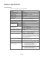
Table 5.1 lists the specifications of the M30220TF-PRB.
Table 5.1 Specifications of the M30220TF-PRB
Emulators
PC4701
Emulation pod main unit
M30200T-RPD-E
Applicable MCUs
M30220 and M30221 Group MCUs
Usable MCU mode
Single-chip mode
Emulation memory
1 MB
Flash memory
(128 K - 32) bytes (Address E0000h - FFFDFh; For how to
use the flash memory, refer to Chapter 4.)
Program/erase iterations of flash memory
Guaranteed for only 100 program/erase iterations
Operating power voltage
2.7 - 5.5 V
Operating frequency
4.0 - 5.5 V
10.0 MHz
2.7 - 5.5 V
7.0 MHz, 1-wait
For no-wait: 5.0 MHz or less
Operating frequency
in CPU rewrite mode
For 1-wait:
10.0 MHz or less
Stack capacity for the emulator
Max. 8 bytes
Suspended cycles in run-time debug
16-byte dump:
16-byte fill:
Power supply to emulation pod
1. Supplied from the emulator main unit
2. The operating voltage of the emulation pod main unit is
determined by detecting the supply voltage of the target
system. When no target system is connected, or when the
supply voltage of the target system is more than 5.0 V, the
operating voltage is 5.0 V.
Operating temperature range
5 to 35°C (no dew)
20 to 30°C (in CPU rewrite mode)
Storage temperature range
-10 to 60°C (no dew)
Connection to the target system
See "3.4 Connecting the Target
System" (page 22).
M30220 Group:
FLX-144NSD (separately available)
for 144-pin 0.5-mm-pitch LQFP (144P6Q-A)
FLX-144NSE (separately available)
for 144-pin 0.4-mm-pitch TQFP (144PFB-A)
approx. 312 BCLK cycles
approx. 283 BCLK cycles
M30221 Group:
FLX-120NSE (separately available)
for 120-pin 0.4-mm-pitch LQFP (120P6R-A)
( 42 / 54 )
5.2 External Dimensions
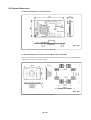
(1) External Dimensions of the Pod Probe
Unit: mm
Figure 5.1 External dimensions of the M30220TF-PRB
(2) External Dimensions of the Converter Board (FLX-144NSD)
Figure 5.2 shows the external dimensions and a sample foot pattern of the pitch converter board FLX144NSD for 144-pin 0.5-mm-pitch LQFP.
Sample foot pattern
Unit: mm
Figure 5.2 External dimensions of the FLX-144NSD
( 43 / 54 )
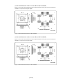
(3) External Dimensions of the Converter Board (FLX-144NSE)
Figure 5.3 shows the external dimensions and a sample foot pattern of the pitch converter board FLX144NSE for 144-pin 0.4-mm-pitch TQFP.
Sample foot pattern
Unit: mm
Figure 5.3 External dimensions of the FLX-144NSE
(4) External Dimensions of the Converter Board (FLX-120NSE)
Figure 5.4 shows the external dimensions and a sample foot pattern of the pitch converter board FLX120NSE for 120-pin 0.4-mm-pitch LQFP.
Sample foot pattern
Unit: mm
Figure 5.4 External dimensions of the FLX-120NSE
( 44 / 54 )
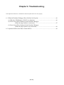
Chapter 6. Troubleshooting
This chapter describes how to troubleshoot when this product does not work properly.
6.1 When the Emulator Debugger Does Not Start Up Properly....................................................... 46
(1) When the LED Display of PC4701 is Abnormal .................................................................. 46
(2) Errors Occur When Starting Up the Emulator Debugger
(When the target system is connected) .................................................................. 47
(3) Errors Occur When Starting Up the Emulator Debugger
(When the target system is not connected) ........................................................... 48
6.2 Operation Differs from That of Actual MCUs ........................................................................... 48
( 45 / 54 )
Chapter 6. Troubleshooting
When this product does not work properly, check the following.
For the latest FAQs, refer to the URL below.
http://www.renesas.com/en/tools
6.1 When the Emulator Debugger Does Not Start Up Properly
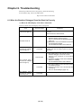
(1) When the LED Display of PC4701 is Abnormal
Table 6.1 LED's abnormal display and its checkpoints
Error
LEDs do not light up.
Connection to
the target system
Checkpoint
-
Recheck the power cable is connected to the
PC4701.
See the PC4701 User's Manual.
(1) Recheck the connection between the
M30200T-RPD-E and this product.
All LEDs remain lit.
-
See "3.3 Connecting the M30200T-RPD-E"
(page 21).
(2) Recheck the connection between the PC4701
and the M30200T-RPD-E.
See the M30200T-RPD-E User's Manual.
The POWER LED of
"STATUS OF TARGET"
does not light up.
Connected
Check power is properly supplied to the target
system and that the target system is properly
grounded.
(1) Check that both the main and sub clocks of the
emulator debugger are not set to "EXT".
Disconnected
See the CLK command of the emulator
debugger.
(2) Check the oscillation circuit in the M30200TRPD-E is oscillating.
The CLOCK LED of
"STATUS OF TARGET"
does not light up.
See the M30200T-RPD-E User's Manual.
Connected
(1) Check the oscillation circuit in the target system
is oscillating properly.
(2) Check the switches of the FLX64-PRB are
correctly set.
See "3.1 Switch Settings" (page 18).
The RESET LED of
"STATUS OF TARGET"
does not go out.
Connected
( 46 / 54 )
Check if the reset pin of the target system is pulled
up.
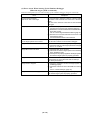
(2) Errors Occur When Starting Up the Emulator Debugger
(When the target system is connected)
Table 6.2 Checkpoints of errors when starting up the emulator debugger (target is connected)
Error
Checkpoint
Communication ERROR
Data is not sent to the target
Check all emulator debugger settings, interface cable
connections and switches on the rear of the PC4701
match.
See the user's manuals of the PC4701 and emulator
debugger.
Target system is not constructed properly (1) Download the proper firmware.
See the user's manual of the emulator debugger.
(2) Recheck the connection between the M30200T-RPDE and this product.
See "3.3 Connecting the M30200T-RPD-E" (page 21).
(3) Recheck the connection between the PC4701 and
the M30200T-RPD-E.
See the M30200T-RPD-E User's Manual.
The version of M3T-PD30 and the firmware Download the proper firmware.
on the target system are not same
See the user's manual of the emulator debugger.
Target MCU is reset state
(1) Check the reset pin of the target system is pulled up.
(2) Check the reset pin of the target system has changed
from "L" to "H" level.
Target MCU cannot be reset
(1) Check the NMI* pin is "H" level.
(2) If the reset circuit of the target system has a watchdog
timer, disable the timer.
(3) Check power is properly supplied to the target system
and that the target system is properly grounded.
Target MCU is in "HOLD" state
The MCU is either in the stop mode or wait mode. Either
reset the MCU or cancel the mode with an interrupt.
See MCU specifications.
Target clock is stopped
(1) Check the oscillation circuit in the target system is
oscillating properly.
(2) Check the switches of the FLX64-PRB are correctly
set.
See "3.1 Switch Settings" (page 18).
Target MCU is not receiving power
( 47 / 54 )
Check power is properly supplied to the target system
and that the target system is properly grounded.
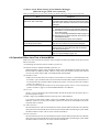
(3) Errors Occur When Starting Up the Emulator Debugger
(When the target system is not connected)
Table 6.3 Checkpoints of errors when starting up emulator debugger (target is not connected)
Error
Checkpoint
Communication ERROR
Data is not sent to the target
Check all emulator debugger settings, interface cable
connections and switches on the rear of the PC4701 match.
See the user's manuals of the PC4701 and emulator
debugger.
Target system is not constructed properly (1) Download the proper firmware.
See the user's manual of the emulator debugger.
(2) Recheck the connection between the M30200T-RPDE and this product.
See "3.3 Connecting the M30200T-RPD-E" (page 21).
(3) Recheck the connection between the PC4701 and
the M30200T-RPD-E.
See the M30200T-RPD-E User's Manual.
The version of M3T-PD30 and the firmware Download the proper firmware.
See the user's manual of the emulator debugger.
on the target are not same
The MCU is either in the stop mode or wait mode. Either
reset the MCU or cancel the mode with an interrupt.
Target MCU is in "HOLD" state
See MCU specifications.
Check the switches of the FLX64-PRB are correctly set.
Target clock is stopped
See "3.1 Switch Settings" (page 18).
6.2 Operation Differs from That of Actual MCUs
Make note of the fact that the operation when using the emulation pod differs from that of actual
MCUs as follows.
(1) Initializing the internal resources of MCU at power-on
(2) Internal memories (ROM and RAM) capacities, etc.
With this emulator system, "INT" (emulation memory ON) is the default for mapping areas other
than the SFR area (addresses 000h - 3FFh). For this reason, the emulation memory can read and
write in areas other than the SFR, internal RAM and internal ROM.
(3) Oscillator circuit
• Make note of the fact that in the oscillator circuit where a resonator is connected between the
XIN and XOUT pins, oscillation does not occur because a flexible cable, buffer IC and other devices
are used between the evaluation MCU and the target system. It is same for sub-clock oscillator
circuits (XCIN and XCOUT ).
• For note on when using the oscillator circuit on the target system, refer to "4.2 (2) Using target
system's oscillator" (page 21) in the M30200T-RPD-E User's Manual.
(4) XOUT pin
The XOUT pin is not assigned to the evaluation MCU used by this product. For this reason, the XOUT
pin of this product is open.
(5) DBC, single-step and BRK instruction interrupt vector table addresses
It is possible to download to DBC, single-step and BRK instruction interrupt vector table
addresses. However, because the emulator system uses these areas, data different from the
expected value is read out.
(6) A-D conversion
The characteristics of A-D converter differ from those of actual MCU because there are a flexible
cable, pitch converter and other devices between the evaluation MCU and the target system. Make
the final evaluation of the A-D converter with the actual MCU.
(7) D-A conversion
The characteristics of D-A converter differ from those of actual MCU because there are a flexible
cable, pitch converter and other devices between the evaluation MCU and the target system. Make
the final evaluation of the D-A converter with the actual MCU.
( 48 / 54 )
Chapter 7. Maintenance and Warranty
This chapter describes how to maintenance, repair provisions and how to request for repair.
7.1 Maintenance ............................................................................................................................... 50
7.2 Warranty ..................................................................................................................................... 50
7.3 Repair Provisions........................................................................................................................ 50
7.4 How to Request for Repair ......................................................................................................... 51
( 49 / 54 )
Chapter 7. Maintenance and Guarantee
7.1 Maintenance
If dust or dirt collects on any equipment of your emulation system, wipe it off with a dry soft cloth.
Do not use thinner or other solvents because these chemicals can cause the equipment's surface
coating to separate.
7.2 Guarantee
If your product becomes faulty within twelve months after its purchase while being used under good
conditions by observing "Precautions for Safety" described in Chapter 1 of this user's manual, we will
repair or replace your faulty product free of charge. Note, however, that if your product's fault is raised
by any one of the following causes, we will repair it or replace it with new one with extra-charge:
• Misuse, abuse, or use under extraordinary conditions
• Unauthorized repair, remodeling, maintenance, and so on
• Inadequate user's system or misuse of it
• Fires, earthquakes, and other unexpected disasters
In the above cases, contact your local distributor. If your product is being leased, consult the leasing
company or the owner.
7.3 Repair Provisions
(1) Repair with extra-charge
The products elapsed more than twelve months after purchase can be repaired with extra-charge.
(2) Replacement with extra-charge
If your product's fault falls in any of the following categories, the fault will be corrected by
replacing the entire product instead of repair, or you will be advised to purchase new one,
depending on the severity of the fault.
• Faulty or broken mechanical portions
• Flaw, separation, or rust in coated or plated portions
• Flaw or cracks in plastic portions
• Faults or breakage caused by improper use or unauthorized repair or modification
• Heavily damaged electric circuits due to overvoltage, overcurrent or shorting of power supply
• Cracks in the printed circuit board or burnt-down patterns
• Wide range of faults that makes replacement less expensive than repair
• Unlocatable or unidentified faults
(3) Expiration of the repair period
When a period of twelve months elapses after the model was dropped from production, repairing
products of the model may become impossible.
(4) Transportation fees at sending your product for repair
Please send your product to us for repair at your expense.
( 50 / 54 )
7.4 How to Request for Repair
If your product is found faulty, follow the procedure below to send your product for repair.
Customer
Fill in the Repair Request Sheet included with this product, then send it
along with this product for repair to your local distributor. Make sure
that information in the Repair Request Sheet is written in as much detail
as possible to facilitate repair.
Distributor
After checking the contents of fault, the distributor should please send
the faulty product along with the Repair Request Sheet to Renesas
Solutions Corp.
Renesas Solutions
When the faulty product is repaired, it will be returned to the customer
at the earliest convenience.
CAUTION
Note on Transporting the Product:
• When sending your product for repair, use the packing box and cushion material supplied with this
product when delivered to you and specify handling caution for it to be handled as precision
equipment. If packing of your product is not complete, it may be damaged during transportation.
When you pack your product in a bag, make sure to use conductive polyvinyl supplied with this
product (usually a blue bag). When you use other bags, they may cause a trouble on your product
because of static electricity.
( 51 / 54 )
MEMO
( 52 / 54 )
M30220TF-PRB User's Manual
Rev.1.00
September 1, 2003
REJ10J0280-0100Z
COPYRIGHT ©2003 RENESAS TECHNOLOGY CORPORATION
AND RENESAS SOLUTIONS CORPORATION ALL RIGHTS RESERVED