1
SAFETY PRECAUTIONS
(Always read these instructions before using this product.)
Before using this product, thoroughly read this manual and the relevant manuals introduced in this manual
and pay careful attention to safety and handle the products properly.
The precautions given in this manual are concerned with this product. For the safety precautions of the
programmable controller system, refer to the User's Manual for the CPU module.
In this manual, the safety precautions are ranked as "
WARNING" and "
CAUTION".
WARNING
Indicates that incorrect handling may cause hazardous conditions, resulting in
death or severe injury.
CAUTION
Indicates that incorrect handling may cause hazardous conditions, resulting in
minor or moderate injury or property damage.
Note that the
CAUTION level may lead to serious consequences according to the circumstances.
Always follow the precautions of both levels because they are important for personal safety.
Please save this manual to make it accessible when required and always forward it to the end user.
[Design Instructions]
WARNING
● When data change, program change, or status control is performed from a personal computer to a running
programmable controller, create an interlock circuit outside the programmable controller to ensure that the whole
system always operates safely.
Furthermore, for the online operations performed from a personal computer to a programmable controller CPU, the
corrective actions against a communication error due to such as a cable connection fault should be predetermined as
a system.
[Startup/Maintenance Instructions]
CAUTION
● The online operations performed from a personal computer to a running programmable controller CPU (Program
change when a programmable controller CPU is RUN, forced input output operation, operating status change such as
RUN-STOP switching, and remote control operation) must be executed after the manual has been carefully read and
the safety has been ensured.
When changing a program while a programmable controller CPU is RUN, it may cause a program corruption in some
operating conditions. Fully understand the precautions described in GX Works2 Version 1 Operating Manual
(Common) before use.
● The positioning test functions of OPR, JOG, inching or positioning data for QD75/LD75 positioning module must be
executed with the programmable controller set to STOP after the manual has been carefully read and the safety has
been ensured. Specially when executing the function on the network system, ensure the safety thoroughly since the
machinery whose operation cannot be checked by an operator may be activated. The operation failure may cause the
injury or machine damage.
● The online operations performed on the intelligent function module such as data writing to flash ROM must be
executed after the operations of the external devices have been carefully considered and the safety has been
ensured.
A-1
CONDITIONS OF USE FOR THE PRODUCT
(1) Mitsubishi programmable controller ("the PRODUCT") shall be used in conditions;
i) where any problem, fault or failure occurring in the PRODUCT, if any, shall not lead to any major or
serious accident; and
ii) where the backup and fail-safe function are systematically or automatically provided outside of the
PRODUCT for the case of any problem, fault or failure occurring in the PRODUCT.
(2) The PRODUCT has been designed and manufactured for the purpose of being used in general
industries.
MITSUBISHI SHALL HAVE NO RESPONSIBILITY OR LIABILITY (INCLUDING, BUT NOT LIMITED
TO ANY AND ALL RESPONSIBILITY OR LIABILITY BASED ON CONTRACT, WARRANTY, TORT,
PRODUCT LIABILITY) FOR ANY INJURY OR DEATH TO PERSONS OR LOSS OR DAMAGE TO
PROPERTY CAUSED BY the PRODUCT THAT ARE OPERATED OR USED IN APPLICATION NOT
INTENDED OR EXCLUDED BY INSTRUCTIONS, PRECAUTIONS, OR WARNING CONTAINED IN
MITSUBISHI'S USER, INSTRUCTION AND/OR SAFETY MANUALS, TECHNICAL BULLETINS AND
GUIDELINES FOR the PRODUCT.
("Prohibited Application")
Prohibited Applications include, but not limited to, the use of the PRODUCT in;
• Nuclear Power Plants and any other power plants operated by Power companies, and/or any other
cases in which the public could be affected if any problem or fault occurs in the PRODUCT.
• Railway companies or Public service purposes, and/or any other cases in which establishment of a
special quality assurance system is required by the Purchaser or End User.
• Aircraft or Aerospace, Medical applications, Train equipment, transport equipment such as Elevator
and Escalator, Incineration and Fuel devices, Vehicles, Manned transportation, Equipment for
Recreation and Amusement, and Safety devices, handling of Nuclear or Hazardous Materials or
Chemicals, Mining and Drilling, and/or other applications where there is a significant risk of injury to
the public or property.
Notwithstanding the above, restrictions Mitsubishi may in its sole discretion, authorize use of the
PRODUCT in one or more of the Prohibited Applications, provided that the usage of the PRODUCT is
limited only for the specific applications agreed to by Mitsubishi and provided further that no special
quality assurance or fail-safe, redundant or other safety features which exceed the general
specifications of the PRODUCTs are required. For details, please contact the Mitsubishi representative
in your region.
A-2
REVISIONS
The manual number is written at the bottom left of the back cover.
Print date
Manual number
Revision
Jan., 2010
SH(NA)-080921ENG-A First edition
Apr., 2010
SH(NA)-080921ENG-B
Model Addition
Q50UDEH, Q100UDEH, LJ72GF15-T2
Addition
Section 1.3, Section 2.1.3, Section 2.1.4, Section 2.1.9, Section 3.1 to Section 3.6,
Section 3.8.4, Section 3.8.5, Appendix 2, Appendix 3
Correction
SAFETY PRECAUTIONS, MANUALS, GENERIC TERMS AND ABBREVIATIONS IN
THIS MANUAL, Section 1.4, Section 2.1, Section 2.1.1, Section 2.1.6, Section 2.4.1,
Section 3.5.5, Appendix 1
Section 1.3 is changed to Section 1.4
Section 2.1.3 to Section 2.1.6 are changed to Section 2.1.5 to Section 2.1.8
Section 3.1 is changed to Section 3.7
Deletion
Section 2.5 to Section 2.10
Sep., 2010
SH(NA)-080921ENG-C
Addition
Section 3.1.3
Correction
GENERIC TERMS AND ABBREVIATIONS IN THIS MANUAL, Section 1.3,
Section 1.4.2, Section 2.1.7, Section 2.4.1, Section 2.4.2, Section 3.1.2,
Section 3.5.1, Section 3.5.2, Section 3.5.3, Section 3.5.5, Section 3.7.1, Appendix 2
Section 3.1.1 is changed to Section 3.1.2, Section 3.1.2 is changed to Section 3.1.1
Jan., 2011
SH(NA)-080921ENG-D
Addition
Section 3.5.1, Section 4.6.6, Section 4.6.7
Correction
Purpose of this manual, Section 1.3, Section 1.4.1, Section 1.4.6, Section 2.1.2,
Section 2.1.4, Section 2.1.7, Section 2.4, Section 3.6.1, Section 4.1, Section 4.5.1,
Section 4.6.1, Section 4.6.2, Section 4.7.2, Appendix 1.1, Appendix 1.2, Appendix 2,
Section 3.5.1 to Section 3.5.6 is changed to Section 3.5.2 to Section 3.5.7
Mar., 2011
SH(NA)-080921ENG-E
Addition
Section 1.4.12
Correction
Purpose of this manual, Section 1.3, Section 2.1.7
Jul., 2011
SH(NA)-080921ENG-F
Model Addition
L02-P, L26-PBT
Addition
Section 3.3.2
Correction
GENERIC TERMS AND ABBREVIATIONS IN THIS MANUAL, Section 1.2,
Section 1.3, Section 1.4.4, Section 2.1.2, Section 2.1.7, Section 2.1.9, Section 3.5.6,
Section 3.6.1, Section 4.2, Appendix 1.1
A-3
Print date
Manual number
Sep., 2011
SH(NA)-080921ENG-G
Revision
Addition
Section 3.5.7
Correction
GENERIC TERMS AND ABBREVIATIONS IN THIS MANUAL, Section 1.2,
Section 1.3, Section 1.4.4, Section 1.4.6, Section 2.1.1, Section 2.1.7, Section 3.3.2,
Section 3.5.8, Section 4.7.2, Appendix 3
Section 3.5.7 is changed to Section 3.5.8
Japanese Manual Version SH-080901-I
This manual confers no industrial property rights or any rights of any other kind, nor does it confer any patent licenses.
Mitsubishi Electric Corporation cannot be held responsible for any problems involving industrial property rights which may occur
as a result of using the contents noted in this manual.
© 2010 MITSUBISHI ELECTRIC CORPORATION
A-4
INTRODUCTION
Thank you for purchasing the Mitsubishi integrated FA software, MELSOFT series.
Before using the product, thoroughly read this manual to develop full familiarity with the functions and
performance to ensure correct use.
CONTENTS
SAFETY PRECAUTIONS ...................................................................................................................... A - 1
CONDITIONS OF USE FOR THE PRODUCT ...................................................................................... A - 2
REVISIONS ........................................................................................................................................... A - 3
INTRODUCTION ................................................................................................................................... A - 5
CONTENTS ........................................................................................................................................... A - 5
MANUALS.............................................................................................................................................. A - 8
GENERIC TERMS AND ABBREVIATIONS IN THIS MANUAL........................................................... A - 16
1
OVERVIEW
1.1
Overview
1-2
1.2
Features of Operations of Intelligent Function Module
1-2
1.3
Intelligent Function Module Data
1-5
1.4
List of Functions
1.4.1
2
1 - 1 to 1 - 18
List of functions common to intelligent function module ............................................................. 1 - 10
1.4.2
List of functions for analog module............................................................................................. 1 - 11
1.4.3
List of functions for temperature input module ........................................................................... 1 - 11
1.4.4
List of functions for temperature control module ........................................................................ 1 - 12
1.4.5
List of functions for counter module............................................................................................ 1 - 12
1.4.6
List of functions for QD75/LD75 positioning module .................................................................. 1 - 13
1.4.7
List of functions for QD70 positioning module ............................................................................ 1 - 15
1.4.8
List of functions for simple motion module ................................................................................. 1 - 15
1.4.9
List of functions for serial communication/modem interface module .......................................... 1 - 16
1.4.10
List of functions for AS-i master module..................................................................................... 1 - 16
1.4.11
List of functions for FL-net (OPCN-2) interface module ............................................................. 1 - 17
1.4.12
List of functions for MODBUS® interface module....................................................................... 1 - 17
COMMON OPERATIONS FOR INTELLIGENT FUNCTION MODULES
2.1
2.2
1 - 10
Operations of Intelligent Function Module Data
2 - 1 to 2 - 28
2-2
2.1.1
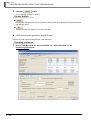
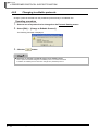
Adding intelligent function module data........................................................................................ 2 - 2
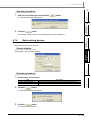
2.1.2
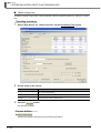
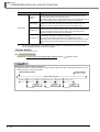
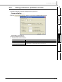
Setting intelligent function module data........................................................................................ 2 - 5
2.1.3
Channel copy/axis copy................................................................................................................ 2 - 9
2.1.4
Data initialization ........................................................................................................................ 2 - 10
2.1.5
Deleting intelligent function modules .......................................................................................... 2 - 10
2.1.6
Displaying properties of intelligent function modules.................................................................. 2 - 11
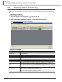
2.1.7
Checking/changing the number of settable intelligent function module parameters .................. 2 - 12
2.1.8
Checking device duplication of auto refresh setting ................................................................... 2 - 18
2.1.9
Changing intelligent function module type.................................................................................. 2 - 19
Utilizing Sample Comments of Intelligent Function Module
2 - 21
A-5
3
2.3
Writing/Reading Intelligent Function Module Data
2 - 21
2.4
Monitoring Intelligent Function Modules
2 - 22
2.4.1
Registering and monitoring intelligent function modules............................................................ 2 - 22
2.4.2
Registering intelligent function modules..................................................................................... 2 - 25
2.4.3
Canceling registration of intelligent function modules ................................................................ 2 - 27
OPERATING INTELLIGENT FUNCTION MODULES
3.1
3.2
Analog Module
3.4
Offset and gain settings ............................................................................................................... 3 - 2
3.1.2
Q61LD two-point calibration......................................................................................................... 3 - 5
3.1.3
Q61LD default settings................................................................................................................. 3 - 7
Temperature Input Module
Automatic tuning ........................................................................................................................ 3 - 10
3.3.2
Sensor correction ....................................................................................................................... 3 - 12
Counter Module
4
3 - 14
Preset function ........................................................................................................................... 3 - 14
QD75/LD75 Positioning Module
3 - 16
Positioning monitor..................................................................................................................... 3 - 16
3.5.2
Positioning test........................................................................................................................... 3 - 20
3.5.3
Wave trace ................................................................................................................................. 3 - 28
3.5.4
Location trace............................................................................................................................. 3 - 31
3.5.5
Requesting parameter initialization and flash ROM write .......................................................... 3 - 34
3.5.6
Convenient functions for editing data......................................................................................... 3 - 35
3.5.7
Saving/reading data of positioning module ................................................................................ 3 - 45
3.5.8
Importing GX Configurator-QP project files................................................................................ 3 - 47
Simple Motion Module
3.6.1
3.7
3 - 10
3.3.1
3.5.1
3.6
3-8
Offset and gain settings ............................................................................................................... 3 - 8
Temperature Control Module
3.4.1
3.5
3-2
3.1.1
3.2.1
3.3
3 - 1 to 3 - 54
3 - 48
Data setting of simple motion module ........................................................................................ 3 - 48
Serial Communication/Modem Interface Module
3 - 49
3.7.1
Applicable CPUs and Modules................................................................................................... 3 - 49
3.7.2
Circuit trace ................................................................................................................................ 3 - 50
3.7.3
Predefined protocol support function ......................................................................................... 3 - 54
3.7.4
Flash ROM operation ................................................................................................................. 3 - 54
PREDEFINED PROTOCOL SUPPORT FUNCTION
4 - 1 to 4 - 46
4.1
List of Functions of Predefined Protocol Support Function
4-2
4.2
Operating Procedure of Predefined Protocol Support Function
4-3
4.3
Starting and Exiting Predefined Protocol Support Function
4-4
4.4
Screen Configuration
4-5
4.5
A-6
4.4.1
Main frame configuration.............................................................................................................. 4 - 5
4.4.2
Status bar..................................................................................................................................... 4 - 6
File Operations of Predefined Protocol Support Function
4-7
4.6
4.7
4.5.1
Creating files................................................................................................................................. 4 - 7
4.5.2
Opening files................................................................................................................................. 4 - 9
4.5.3
Saving files ................................................................................................................................... 4 - 9
4.5.4
Closing files .................................................................................................................................. 4 - 9
Editing Protocols
4.6.1
Adding protocols......................................................................................................................... 4 - 10
4.6.2
Changing to editable protocols ................................................................................................... 4 - 12
4.6.3
Configuring details of protocols .................................................................................................. 4 - 13
4.6.4
Setting send/receive parameters in batch .................................................................................. 4 - 15
4.6.5
Deleting protocols/packets ......................................................................................................... 4 - 16
4.6.6
Saving protocols as user protocol library.................................................................................... 4 - 16
4.6.7
Registering predefined protocol library....................................................................................... 4 - 18
Setting Packets
4.7.1
4.8
4.9
4.10
4 - 10
4 - 19
Adding new elements ................................................................................................................. 4 - 22
4.7.2
Setting elements......................................................................................................................... 4 - 22
4.7.3
Changing element types............................................................................................................. 4 - 28
4.7.4
Batch-setting devices ................................................................................................................. 4 - 29
4.7.5
Confirming set devices in list view.............................................................................................. 4 - 30
Writing/Reading/Verifying Protocol Settings
4 - 31
4.8.1
Writing/reading protocol settings ................................................................................................ 4 - 31
4.8.2
Verifying protocol settings in personal computer side with those in module side....................... 4 - 33
Debugging
4 - 35
4.9.1
Selecting debugging target modules .......................................................................................... 4 - 35
4.9.2
Displaying protocol execution logs ............................................................................................. 4 - 36
4.9.3
State monitor .............................................................................................................................. 4 - 38
Printing Protocol Settings
4 - 43
4.10.1
Print screen ................................................................................................................................ 4 - 43
4.10.2
Print examples............................................................................................................................ 4 - 44
APPENDIX
App - 1 to App - 6
Appendix 1 List of Toolbars and Shortcut Keys
App - 2
Appendix 1.1
Common toolbars and shortcut keys ...............................................................................App - 2
Appendix 1.2
Shortcut keys for operating intelligent function module data ...........................................App - 4
Appendix 2 Compatibility with GX Configurator-QP
App - 5
Appendix 3 Procedure for Use of GX Configurator-QP
App - 5
INDEX
INDEX - 1 to INDEX - 3
A-7
■
MANUALS
Related manuals are separately issued according to the purpose of their functions in GX Works2.
● Related manuals
The manuals related to this product are shown below.
Refer to the following tables when ordering required manuals.
1)
Operation of GX Works2
Manual name
Manual number
(Model code)
GX Works2 Version 1 Operating Manual (Common)
Explains the system configuration of GX Works2 and the functions common to Simple project and
Structured project such as parameter setting, operation method for the online function. (Sold separately)
SH-080779ENG
(13JU63)
GX Works2 Version 1 Operating Manual (Simple Project)
Explains operation methods such as creating and monitoring programs in Simple project of GX Works2.
(Sold separately)
SH-080780ENG
(13JU64)
GX Works2 Version 1 Operating Manual (Structured Project)
Explains operation methods such as creating and monitoring programs in Structured project of GX
Works2.
(Sold separately)
SH-080781ENG
(13JU65)
GX Works2 Beginner's Manual (Simple Project)
Explains fundamental operation methods such as creating, editing, and monitoring programs in Simple
project for users inexperienced with GX Works2.
(Sold separately)
SH-080787ENG
(13JZ22)
GX Works2 Beginner's Manual (Structured Project)
Explains fundamental operation methods such as creating, editing, and monitoring programs in
Structured project for users inexperienced with GX Works2.
(Sold separately)
SH-080788ENG
(13JZ23)
2)
Structured programming
Manual name
Manual number
(Model code)
MELSEC-Q/L/F Structured Programming Manual (Fundamentals)
Explains the programming methods, types of programming languages, and other information required to
create structured programs.
(Sold separately)
SH-080782ENG
(13JW06)
MELSEC-Q/L Structured Programming Manual (Common Instructions)
Explains the specifications and functions of common instructions such as sequence instructions, basic
instructions, and application instructions, that can be used in structured programs.
(Sold separately)
SH-080783ENG
(13JW07)
MELSEC-Q/L Structured Programming Manual (Application Functions)
Explains the specifications and functions of application functions that can be used in structured
programs.
(Sold separately)
SH-080784ENG
(13JW08)
MELSEC-Q/L Structured Programming Manual (Special Instructions)
Explains the specifications and functions of special instructions such as module dedicated instruction,
PID control instruction, and built-in I/O function dedicated instruction, that can be used in structured
programs.
(Sold separately)
SH-080785ENG
(13JW09)
FXCPU Structured Programming Manual (Device & Common)
Explains the devices and parameters provided in GX Works2 for structured programming.
(Sold separately)
JY997D26001
(09R925)
FXCPU Structured Programming Manual (Basic & Applied Instruction)
Explains the sequence instructions provided in GX Works2 for structured programming.
(Sold separately)
JY997D34701
(09R926)
FXCPU Structured Programming Manual (Application Functions)
Explains the application functions provided in GX Works2 for structured programming.
(Sold separately)
A-8
JY997D34801
(09R927)
3)
Operation of iQ Works
Manual name
Manual number
(Model code)
iQ Works Beginner’s Manual
Explains fundamental operation methods such as managing the system using MELSOFT Navigator and
using system labels for users inexperienced with GX Works2.
(Sold separately)
SH-080902ENG
(13JZ44)
4)
User's manual of each intelligent function module
The Operating Manuals are included on the CD-ROM of the software package in a PDF file format.
Manuals in printed form are sold separately for single purchase. Order a manual by quoting the manual
number (model code) listed in the table above.
A-9
● Purpose of this manual
This manual explains the operation related to the intelligent function modules using the functions
supported by GX Works2.
Manuals for reference are listed in the following table according to their purpose.
For information such as the contents and number of each manual, refer to the list of 'Related
manuals'.
1)
Operation of GX Works2
Purpose
Installation
Learning the operating
environment and
installation method
GX Works2
Installation
Instructions
GX Works2
Beginner's Manual
Simple
Project
Structured
Project
Learning the operations
of available functions
regardless of project
type.
Learning the functions
and operation methods
for programming
Learning data setting
methods for intelligent
function module
A - 10
Structured
Project
Details
Details
Intelligent
Function
Module
Outline
Learning the project
types and available
languages in GX Works2
Learning the basic
operations and operating
procedures when
creating a structured
project for the first time
Simple
Project
Details
Learning all functions of
GX Works2
Operation of
GX Works2
Common
Details
Learning a USB driver
installation method
Learning the basic
operations and operating
procedures when
creating a simple project
for the first time
GX Works2 Version 1
Operating Manual
Outline
Details
Details
Details
Outline
Details
2)
Operations in each programming language
For details of instructions used in each programming language, refer to the section 3 on the next
page.
Purpose
GX Works2
Beginner's Manual
Simple
Project
GX Works2 Version 1
Operating Manual
Structured
Project
Ladder
Simple
Project
Structured
Project
Details
Outline
Simple
Project
SFC
*1
Details
Outline
ST
Details
Outline
Ladder
Details
Outline
SFC
*1
Details
Outline
Structured
Project
Structured ladder/FBD
Details
Outline
ST
Details
Outline
*1: MELSAP3 and FX series SFC only
A - 11
3)
Details of instructions in each programming language (for QCPU (Q mode)/LCPU)
Purpose
MELSECQ/L/F
Structured
Programming
Manual
Fundamentals
All
languages
MELSEC-Q/L Structured
Programming Manual
Common
Instructions
Special
Instructions
Application
Functions
Learning details of
programmable
controller CPU
error codes,
special relays,
and special
registers
SFC
Learning the
types and details
of instructions for
intelligent function
modules
Details
Details
Learning details of
specifications,
functions, and
instructions of
SFC (MELSAP3)
Learning the
types and details
of common
instructions
Learning the
types and details
Using
of instructions for
structured intelligent function
ladder/FBD modules
/ST
Learning the
types and details
language
of instructions for
network modules
Learning the
types and details
of instructions for
the PID control
function
Learning the
types and details
of application
functions
−
Details
Learning the
types and details
of instructions for
network modules
Learning the
fundamentals for
creating a
structured
program
A - 12
PID Control
Instructions
Details
Learning the
types and details
of instructions for
the PID control
function
Using SFC
language
Common
Instructions
MELSEC-Q/L/QnA
Programming Manual
Manual
for
module
to be
used
Details
Learning the
types and details
of common
instructions
Using
ladder
language
MELSECQ/L
Programming
Manual
Details
Details
Details
Details
Outline
Details
Outline
Details
Outline
Details
4)
Details of instructions in each programming language (for FXCPU)
Purpose
MELSECQ/L/F
Structured
Programming
Manual
Fundamentals
Using
ladder
language
Learning the
types and details
of basic/
application
instructions,
descriptions of
devices and
parameters
Using SFC
language
Learning details of
specifications,
functions, and
instructions of
SFC
Learning the
fundamentals for
creating a
structured
program
Using
structured
ladder/
FBD/ST
language
Learning the
descriptions of
devices,
parameters, and
error codes
Learning the
types and details
of sequence
instructions
Learning the
types and details
of application
instructions
FXCPU Structured Programming Manual
Device &
Common
Basic &
Applied
Instruction
Application
Functions
FXCPU Programming Manual
FX0, FX0S,
FX0N, FX1,
FXU, FX2C
FX1S, FX1N,
FX2N, FX1NC,
FX2NC
FX3G, FX3U,
FX3UC
Details
Details
Details
Details
Details
Details
Details
Details
Details
Details
A - 13
● How to read this manual
Screen display
Describes the screen display procedure.
Follow the
and select [(menu)] to open
the screen.
*Screen display may depend on the CPU.
In that case, typical example is described.
Chapter heading
Index on the right of the page number clarifies
the chapter of currently open page.
Display contents
Describes the display contents in the screen.
Operating procedure
Describes the operating procedure of the
function.
Section title
Clarifies the section of currently open page.
Screen button
Describes the buttons in the screen.
Reference location
leads to the reference location and
reference manual.
A - 14
This manual also uses the following columns:
This explains notes requiring attention or useful functions relating to the information given on the
same page.
Restrictions
This explains restrictions relating to the information given on the same page.
● Symbols used in this manual
The following shows the symbols used in this manual with descriptions and examples.
1
2
3
4
5
6
No.
1
Symbol
[
]
(Underline)
4
5
Menu name on a menu bar
Example
[Project]
Toolbar icon
2
3
Description
"
"
Screen name
Q Parameter Setting screen
Tab name in a screen
<<PLC System>>
Item name in a screen
"Timer Limit Setting"
6
Button on a screen
−
Keyboard key
button
A - 15
■
GENERIC TERMS AND ABBREVIATIONS IN THIS MANUAL
This manual uses the generic terms and abbreviations listed in the following table to discuss the
software packages and programmable controller CPUs. Corresponding module models are also listed if
needed.
Generic term and
abbreviation
Description
GX Works2
Generic product name for SWnDNC-GXW2-E
(n: version)
Existing application
−
GX Developer
Generic product name for SWnD5C-GPPW-E, SWnD5C-GPPW-EA, SWnD5C-GPPW-EV, and
SWnD5C-GPPW-EVA
(n: version)
GX IEC Developer
Generic product name for SWnD5C-MEDOC3
(n: version)
GX Simulator
Generic product name for SWnD5C-LLT-E, SWnD5C-LLT-EA, SWnD5C-LLT-EV, and SWnD5C-LLTEVA
(n: version)
GX Configurator
Generic product name for GX Configurator-AD/DA/SC/CT/TC/TI/FL/PT/AS/QP
MELSOFT Navigator
Product name for the integrated development environment included in SWnDNC-IQWK (iQ Platform
compatible engineering environment MELSOFT iQ Works)
(n: version)
iQ Works
Abbreviation for iQ platform supporting engineering environment MELSOFT iQ Works
Personal computer
Generic term for personal computer on which Windows® operates
Basic model QCPU
Generic term for Q00J, Q00, and Q01
High Performance
model QCPU
Generic term for Q02, Q02H, Q06H, Q12H, and Q25H
Universal model QCPU
Generic term for Q00UJ, Q00U, Q01U, Q02U, Q03UD, Q03UDE, Q04UDH, Q04UDEH, Q06UDH,
Q06UDEH, Q10UDH, Q10UDEH, Q13UDH, Q13UDEH, Q20UDH, Q20UDEH, Q26UDH,
Q26UDEH, Q50UDEH, and Q100UDEH
Built-in Ethernet port
QCPU
Generic term for Q03UDE, Q04UDEH, Q06UDEH, Q10UDEH, Q13UDEH, Q20UDEH, Q26UDEH,
Q50UDEH, and Q100UDEH
QCPU (Q mode)
Generic term for Basic model QCPU, High Performance model QCPU, and Universal model QCPU
LCPU
Generic term for L02, L02-P, L26-BT, and L26-PBT
CPU module
Generic term for QCPU (Q mode) and LCPU
A/D converter module
Generic term for Q64AD, Q68ADV, Q68ADI, Q64AD-GH, Q62AD-DGH, Q68AD-G, Q66AD-DG, and
L60AD4
D/A converter module
Generic term for Q62DAN, Q64DAN, Q68DAVN, Q68DAIN, Q62DA, Q64DA, Q68DAV, Q68DAI,
Q62DA-FG, Q66DA-G, and L60DA4
QD75M/QD75MH
Generic term for QD75M1, QD75M2, QD75M4, QD75MH1, QD75MH2, and QD75MH4
QD75 positioning
module
Generic term for QD75P1, QD75P2, QD75P4, QD75P1N, QD75P2N, QD75P4N, QD75D1,
QD75D2, QD75D4, QD75D1N, QD75D2N, QD75D4N, QD75M1, QD75M2, QD75M4, QD75MH1,
QD75MH2, and QD75MH4
LD75 positioning module Generic term for LD75P4 and LD75D4
A - 16
QD75/LD75 positioning
module
Generic term for QD75 positioning module and LD75 positioning module
Serial communication
module
Generic term for QJ71C24, QJ71C24-R2, QJ71C24N, QJ71C24N-R2, QJ71C24N-R4, LJ71C24,
and LJ71C24-R2
Simple Motion Module
Generic term for LD77MH4, LD77MH16
Q series C24N
Generic term for QJ71C24N, QJ71C24N-R2, and QJ71C24N-R4
L series C24
Generic term for LJ71C24 and LJ71C24-R2
Common instruction
Generic term for sequence instructions, basic instructions, application instructions, data link
instructions, multiple CPU dedicated instructions, and multiple CPU high-speed transmission
dedicated instructions
Special instruction
Generic term for module dedicated instructions, PID control instructions, socket communication
function instructions, built-in I/O function instructions, and data logging function instructions
OVERVIEW
2
This manual describes operating methods of the intelligent function module, such as setting parameters,
writing/reading data, monitoring.
For the features and functions of GX Works2, refer to the following manual.
GX Works2 Version 1 Operating Manual (Common)
COMMON OPERATIONS
FOR INTELLIGENT
FUNCTION MODULES
1
OVERVIEW
1
OPERATING
INTELLIGENT
FUNCTION MODULES
3
4
PREDEFINED
PROTOCOL SUPPORT
FUNCTION
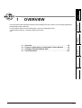
Overview . . . . . . . . . . . . . . . . . . . . . . . . . . . . . . . . . . . . . . . . . . 1-2
Features of Operations of Intelligent Function Module . . . . . 1-2
Intelligent Function Module Data . . . . . . . . . . . . . . . . . . . . . . . 1-5
List of Functions . . . . . . . . . . . . . . . . . . . . . . . . . . . . . . . . . . . 1-10
APPENDIX
A
I
INDEX
1.1
1.2
1.3
1.4
1-1
GX Works2
1 OVERVIEW
1.1
Overview
This manual describes operations of the intelligent function module with GX Works2.
The operations of the intelligent function module with GX Works2 enable to easily set, monitor, and test
settings and parameters, such as the intelligent function module parameters (initial setting/auto refresh) for
the analog module, the system settings for the serial communication module, and the positioning data and
parameters for the positioning module, without regard for the input/output signals and buffer memory.
For the detailed settings of the intelligent function module, refer to the user's manual of the module to be used.
1.2
■
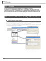
Features of Operations of Intelligent Function Module
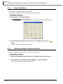
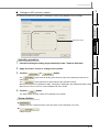
Adding intelligent function modules
By adding an intelligent function module to a project, its data such as the intelligent function module
parameters (initial setting/auto refresh) can be set, monitored, and tested.
In addition, the I/O assignment information of the added intelligent function module are reflected to the
I/O assignment setting of the PLC parameter.
Add an intelligent function module
Manage intelligent function modules
on the Project view
Reflect the settings to the I/O assignment setting of the PLC parameter
1-2
1.2 Features of Operations of Intelligent Function Module
1
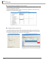
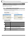
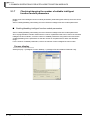
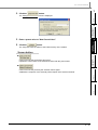
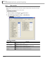
Setting data to intelligent function modules
<Intelligent function module parameter list>
3
OPERATING
INTELLIGENT
FUNCTION MODULES
<Data setting screen for the intelligent function module>
2
COMMON OPERATIONS
FOR INTELLIGENT
FUNCTION MODULES
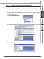
The intelligent function module parameters can be set by opening the data of each intelligent
function module on the Project view.
On the intelligent function module parameter list, the number of set parameters (initial setting/auto
refresh) can be checked. In addition, the enabled/disabled status of the parameters can be
switched.
The number of settable parameters (initial setting/auto refresh) may differ depending on the CPU
module to be used.
For details of the limit of the number of parameters depending on the CPU module, refer to Section
2.1.7.
OVERVIEW
● Intelligent function module parameters (initial setting/auto refresh)
PREDEFINED
PROTOCOL SUPPORT
FUNCTION
4
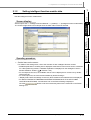
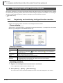
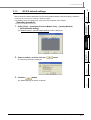
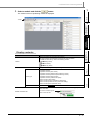
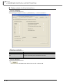
The switch setting of the intelligent function module can easily be performed without regard to the
order of bits.
The switch setting of the intelligent function module links with the switch setting of the PLC
parameter.
<Switch setting of the intelligent function module>
<Switch setting of the PLC parameter>
A
APPENDIX
● Switch setting of intelligent function module
I
INDEX
■
● Writing/reading data to/from intelligent function module
Using the Write to PLC and Read from PLC functions, the intelligent function module parameters
can be written/read. Data can also be written/read to/from the buffer memory and flash ROM.
1-3
GX Works2
1 OVERVIEW
■
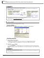
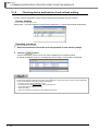
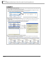
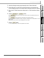
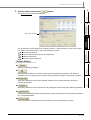
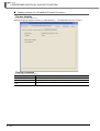
Monitoring/testing intelligent function modules
On the Intelligent Function Module Monitor windows, the input/output signals and buffer memory can be
monitored on module by module basis.
The input/output signals and buffer memory can be tested by changing their current values on the
Intelligent Function Module Monitor window.
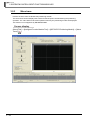
<Monitoring of the serial communication module>
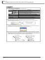
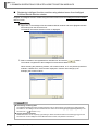
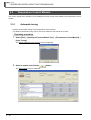
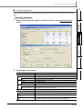
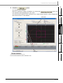
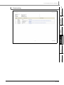
■
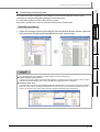
Intelligent function module tools
The offset/gain setting of the analog module and temperature input module, the circuit trace of the
serial communication module, and etc. can be performed using the intelligent function module tools.
For details of the intelligent function module tools, refer to Chapter 3.
<Offset/gain setting of the analog module>
1-4
<Circuit trace of the serial communication module>
1.3 Intelligent Function Module Data
● QCPU (Q mode)
Q64AD
Q68ADV
Q68ADI
Q64AD-GH
Q62AD-DGH
Q68AD-G
Q66AD-DG
Analog Module
Q62DAN
Q64DAN
Q68DAVN
Q68DAIN
Q62DA
Q64DA
Q68DAV
Q68DAI
Q62DA-FG
Q66DA-G
Q64AD2DA
Q61LD
Temperature
Input Module
Q64RD
Q64RD-G
Q64TD
Q64TDV-GH
Q68TD-G-H02
Q68TD-G-H01
Q68RD3-G
Data
Description
Initial
setting
Auto
refresh
−
−
Switch Setting
Set the intelligent function module switches.
Parameter
Set the basic settings and warning output function
settings.
Auto Refresh
Set the devices for auto refresh.
−
Switch Setting
Set the intelligent function module switches.
−
Parameter
Set the basic settings and warning output function
settings.
Auto Refresh
Set the devices for auto refresh.
−
Switch Setting
Set the intelligent function module switches.
−
Parameter (A/D
conversion part)
Set the basic settings, scaling function settings, shift
function, input signal error detected function, and logging
function.
−
Parameter (D/A
conversion part)
Set the basic settings, scaling function settings, and shift
function.
−
Auto Refresh
Set the devices for auto refresh.
Parameter
Set the basic settings and warning output function
settings.
Auto Refresh
Set the devices for auto refresh.
−
Switch Setting
Set the intelligent function module switches.
−
Parameter
Set the basic settings, warning output function settings,
and scaling function settings.
Auto Refresh
Set the devices for auto refresh.
−
4
−
−
PREDEFINED
PROTOCOL SUPPORT
FUNCTION
Module model
3
A
−
APPENDIX
Module type
Intelligent function
module parameter
2
COMMON OPERATIONS
FOR INTELLIGENT
FUNCTION MODULES
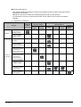
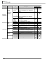
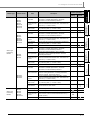
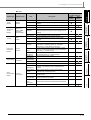
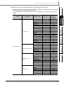
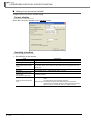
Intelligent function module parameters are created when the intelligent function data are set. The intelligent
function module parameters include the data for initial setting and auto refresh.
The following table shows the intelligent function module data and the data registered to the intelligent
function module parameters as initial setting and auto refresh.
Note that the auto refresh configures the settings to automatically store the error information and status
information stored in buffer memory to the specified device in the programmable controller CPU.
OPERATING
INTELLIGENT
FUNCTION MODULES
This section explains intelligent function module data which can be used in GX Works2.
For details of each item, refer to the user’s manual of the module to be used.
OVERVIEW
1
Intelligent Function Module Data
I
−
−
−
−
−
1-5
INDEX
1.3
GX Works2
1 OVERVIEW
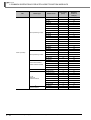
Module type
Temperature
Control Module
Module model
Q64TCTT
Q64TCTTBW
Q64TCRT
Q64TCRTBW
Q64TCTTN
Q64TCTTBWN
Q64TCRTN
Q64TCRTBWN
Q62HLC
QD62
QD62E
QD62D
QD63P6
Counter Module QD64D2
QD60P8-G
QD65PD2
1-6
Data
Description
Intelligent function
module parameter
Initial
setting
Auto
refresh
−
−
Switch Setting
Set the intelligent function module switches.
Parameter
Set the basic settings, control basic parameters, control
detailed parameters, warning function settings, and CT
settings.
Auto Refresh
Set the devices for auto refresh.
−
Switch Setting
Set the intelligent function module switches.
−
−
−
Set the basic setting, control basic parameters, control
Parameter (MAIN) detailed parameters, warning function settings, and
scaling settings.
−
Parameter
(Program Control
Function)
−
Set the program control function settings.
Auto Refresh
Set the devices for auto refresh.
−
Switch Setting
Set the intelligent function module switches.
−
Parameter
Set the basic settings and counter function settings.
Auto Refresh
Set the devices for auto refresh.
−
Switch Setting
Set the intelligent function module switches.
−
Parameter
Set the basic settings and periodic pulse counter function
settings.
−
−
−
−
Auto Refresh
Set the devices for auto refresh.
−
Switch Setting
Set the intelligent function module switches.
−
Parameter
Set the basic settings, coincidence output function, and
continuous comparison function settings.
Auto Refresh
Set the devices for auto refresh.
−
Switch Setting
Set the intelligent function module switches.
−
Parameter
Set the basic settings and warning output function
settings.
−
−
−
−
Auto Refresh
Set the devices for auto refresh.
−
Switch Setting
Set the intelligent function module switches.
−
Parameter
Set the basic settings.
Auto Refresh
Set the devices for auto refresh.
−
−
−
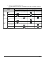
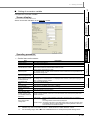
1.3 Intelligent Function Module Data
QD75 Type
Positioning
Module
QD75M1
QD75M2
QD75M4
QD75MH1
QD75MH2
QD75MH4
QD70 Type
Positioning
Module
QD70P4
QD70P8
QD70D4
QD70D8
QD72P3C3
Parameter
Set the basic parameters 1, basic parameters 2, detailed
parameters 1, detailed parameters 2, OPR basic
parameters, and OPR detailed parameters.
−
−
Positioning Data
Axis #n
Set the positioning data including the pattern, control
method, acceleration/deceleration time, and address for
each axis. (n = number of axes)
−
−
Block Starting
Data Axis #n
Set the execution sequence and execution conditions for
the positioning data. (n = number of axes)
−
−
Auto Refresh
Set the devices for auto refresh.
−
Parameter
Set the basic parameters 1, basic parameters 2, detailed
parameters 1, detailed parameters 2, OPR basic
parameters, and OPR detailed parameters.
−
Positioning Data
Axis #n
Set the positioning data including the pattern, control
method, acceleration/deceleration time, and address for
each axis. (n = number of axes)
−
−
Block Starting
Data Axis
Set the execution sequence and execution conditions for
the positioning data. (n = number of axes)
−
−
Auto Refresh
Set the devices for auto refresh.
−
Parameter
Set the basic parameters 1, basic parameters 2, detailed
parameters 1, detailed parameters 2, OPR basic
parameters, and OPR detailed parameters.
−
−
Servo parameter
Set the servo basic parameters, servo regulation
parameters, servo extended parameters, and servo
extended parameters 2.
−
−
Positioning Data
Axis #n
Set the positioning data including the pattern, control
method, acceleration/deceleration time, and address for
each axis. (n = number of axes)
−
−
Block Starting
Data Axis #n
Set the execution sequence and execution conditions for
the positioning data. (n = number of axes)
−
−
Auto Refresh
Set the devices for auto refresh.
−
Parameter
Set the basic parameters 1, basic parameters 2, detailed
parameters 1, detailed parameters 2, OPR basic
parameters, and OPR detailed parameters.
−
−
Servo Parameter
Set the basic setting parameters, gain/filter parameters,
extension setting parameters, I/O setting parameters,
extension settings, and special settings.
−
−
Positioning Data
Axis #n
Set the positioning data including the pattern, control
method, acceleration/deceleration time, and address for
each axis. (n = number of axes)
−
−
Block Starting
Data Axis #n
Set the execution sequence and execution conditions for
the positioning data. (n = number of axes)
−
−
Auto Refresh
Set the devices for auto refresh.
−
Switch Setting
Set the intelligent function module switches.
−
−
OVERVIEW
Auto
refresh
2
COMMON OPERATIONS
FOR INTELLIGENT
FUNCTION MODULES
Initial
setting
3
OPERATING
INTELLIGENT
FUNCTION MODULES
QD75D1
QD75D2
QD75D4
QD75D1N
QD75D2N
QD75D4N
Description
4
PREDEFINED
PROTOCOL SUPPORT
FUNCTION
QD75P1
QD75P2
QD75P4
QD75P1N
QD75P2N
QD75P4N
Data
A
APPENDIX
Module model
1
I
INDEX
Module type
Intelligent function
module parameter
−
Parameter
Set the basic parameters and OPR parameters.
−
Positioning Data
Axis #n
Set the positioning data including the operation pattern,
control method, and acceleration/deceleration time. (n =
number of axes)
−
Auto Refresh
Set the devices for auto refresh.
−
1-7
GX Works2
1 OVERVIEW
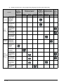
Module type
Serial
Communication/
Modem
Interface
Module
AS-i Master
Module
FL-net
(OPCN-2)
Interface
Module
MODBUS®
Interface
Module
Module model
QJ71C24N
QJ71C24N-R2
QJ71C24N-R4
QJ71C24
QJ71C24-R2
QJ71AS92
QJ71FL71-F01
QJ71FL71-T-F01
QJ71FL71-B2-F01
QJ71FL71-B5-F01
QJ71FL71
QJ71FL71-T
QJ71FL71-B2
QJ71FL71-B5
Data
Description
Initial
setting
Auto
refresh
Switch Setting
Set the intelligent function module switches.
−
−
Various Control
Specifications
Make system settings for transmission control, MC
protocol, nonprocedural protocol, and bidirectional
protocol.
−
−
PLC Monitoring
Function
Make system settings to use the programmable
controller CPU monitoring function.
−
−
Modem Function
Make system settings for data communications using the
model function. (Not available for QJ71C24N-R4)
−
−
User Register
Frame Content
Set the contents of user frames.
−
−
User Register
Frame
Specification
Set the frame numbers for data transmission/reception.
−
−
Auto Refresh
Set the devices for auto refresh.
−
Auto Refresh
(System
Common)
Set the devices for auto refresh.
−
Auto Refresh
(System
Individual)
Set the devices for auto refresh.
−
Switch Setting
Set the intelligent function module switches.
−
Parameter
Set the basic settings.
Auto Refresh
Set the devices for auto refresh.
−
Switch Setting
Set the intelligent function module switches.
−
Basic Parameter
(Router
Information)
Set the TCP/UDP/IP, GX Works2 connection.
−
Set the MODBUS®/TCP.
−
Set the automatic communication parameter.
−
Basic Parameter
(Preferred Node
Specification
QJ71MT91
QJ71MB91
Intelligent function
module parameter
(MODBUS®
−
−
/TCP
settings)
Automatic
Communication
Parameter
MODBUS® Device
Assignment
Set the MODBUS® device assignment parameter.
Parameter
Auto Refresh
1-8
−
Set the devices for auto refresh.
−
−
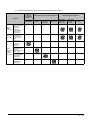
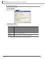
1.3 Intelligent Function Module Data
1
● LCPU
LD75 Type
Positioning
Module
Simple Motion
Serial
Communication
Module
LD62
LD62D
LD75P4
LD75D4
LD77MH4
LD77MH16
LJ71C24
LJ71C24-R2
Auto
refresh
−
−
Switch Setting
Set the intelligent function module switches.
Parameter
Set the basic settings and warning output function
settings.
Auto Refresh
Set the devices for auto refresh.
−
Switch Setting
Set the intelligent function module switches.
−
Parameter
Set the basic settings, control basic parameters, control
detailed parameters, warning function settings, and CT
settings.
Auto Refresh
Set the devices for auto refresh.
−
Switch Setting
Set the intelligent function module switches.
−
Parameter
Set the basic settings and warning output function
settings.
Auto Refresh
Set the devices for auto refresh.
−
Parameter
Set the basic parameters 1, basic parameters 2, detailed
parameters 1, detailed parameters 2, OPR basic
parameters, and OPR detailed parameters.
−
−
Positioning Data
Axis #n
Set the positioning data including the pattern, control
method, acceleration/deceleration time, and address for
each axis. (n = number of axes)
−
−
Block Starting
Data Axis #n
Set the execution sequence and execution conditions for
the positioning data. (n = number of axes)
−
−
Auto Refresh
Set the devices for auto refresh.
−
Simple Motion
Module Setting
Start the simple motion module setting tool.
−
Auto Refresh
Set the devices for auto refresh.
−
Switch Setting
Set the intelligent function module switches.
−
−
Various Control
Specifications
Make system settings for transmission control, MC
protocol, nonprocedural protocol, and bidirectional
protocol.
−
−
PLC Monitoring
Function
Make system settings to use the programmable
controller CPU monitoring function.
−
−
Modem Function
Make system settings for data communications using the
model function.
−
−
User Register
Frame Content
Set the contents of user frames.
−
−
User Register
Frame
Specification
Set the frame numbers for data transmission/reception.
−
−
Auto Refresh
Set the devices for auto refresh.
−
OVERVIEW
Initial
setting
2
COMMON OPERATIONS
FOR INTELLIGENT
FUNCTION MODULES
−
−
−
3
−
−
OPERATING
INTELLIGENT
FUNCTION MODULES
Counter
L60TCTT4
L60TCTT4BW
L60TCRT4
L60TCRT4BW
Description
4
PREDEFINED
PROTOCOL SUPPORT
FUNCTION
Temperature
Control
Module
L60AD4
L60DA4
Data
−
A
APPENDIX
Analog
Module
Module model
I
INDEX
Module type
Intelligent function
module parameter
1-9
GX Works2
1 OVERVIEW
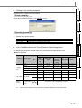
1.4
List of Functions
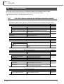
This section shows the list of functions of GX Works2 related to the intelligent function module.
For (Common) indicated in the Reference column, refer to the following manual.
GX Works2 Version 1 Operating Manual (Common)
1.4.1
List of functions common to intelligent function module
The following tables show the functions common to operations of the intelligent function module.
Project (common function)
Reference
−
Intelligent Function Module
New Module
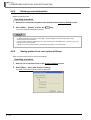
Add new intelligent function module data.
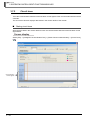
Section 2.1.1
Delete Module
Delete intelligent function module data.
Section 2.1.5
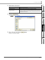
Property
Display properties of an intelligent function module data.
Section 2.1.6
Intelligent Function Module Parameter
List
Display a list of set/unset parameters of an intelligent
function module.
Section 2.1.7
Print Window
Print the open screen.
Print Window Preview
Display the print preview of the open screen.
Printer Setup
Change the printer settings.
View (common function)
(Common)
Reference
−
Docking Window
Intelligent Function Module Monitor
Intelligent Function Module Monitor Display/hide the Intelligent Function Module Monitor window.
1 to 10
Intelligent Function Module Guidance
Display/hide the Intelligent Function Module Guidance
window.
Online (common function)
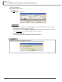
Read from PLC
Read data from the programmable controller CPU.
Write to PLC
Write data to the programmable controller CPU.
Section 3.5.6
Reference
(Common)
−
Monitor
Start Monitoring (All Windows)
Start monitoring of all open windows.
Stop Monitoring (All Windows)
Stop monitoring of all open windows.
Start Monitoring
Start monitoring of the open window.
Stop Monitoring
Stop monitoring of the open window.
(Common)
−
Watch
Start Watching
Start monitoring the current values of registered devices/
labels and intelligent function module.
Stop Watching
Stop monitoring the current values of registered devices/
labels and intelligent function module.
Tool (common function)
Check Auto Refresh Duplication
Section 2.4
Reference
−
Check Intelligent Function Module Parameter
1 - 10
Section 2.4
Check the duplication of devices set in the Auto refresh
function and displays the result.
1.4.1 List of functions common to intelligent function module
Section 2.1.8
1.4 List of Functions
1.4.2
1
List of functions for analog module
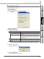
Utilize specified channel data to another channel.
Section 2.1.3
Auto Device Assignment
Assign sequential devices to the items selected for auto
refresh.
Section 2.1.2
2
Edit (analog module)
Reference
View (analog module)
Reference
Automatic Adjustment for Width
Automatically adjust the width of intelligent function module
data table.
3
Set an offset/gain of analog module.
Section 3.1.1
Q61LD Two-Point Calibration
Setting
Set a Q61LD two-point calibration.
Section 3.1.2
4
Reference
−
−
Analog Module
Q61LD Default Setting
Data Initialization
−
Configure the Q61LD default setting.
Section 3.1.3
Initialize the set data of specified channel.
Section 2.1.4
List of functions for temperature input module
PREDEFINED
PROTOCOL SUPPORT
FUNCTION
Offset/Gain Setting
Tool (analog module)
Intelligent Function Module Tool
1.4.3
Section 2.1.2
OPERATING
INTELLIGENT
FUNCTION MODULES
Automatic Adjustment for Height
Automatically adjust the height of intelligent function module
data table.
COMMON OPERATIONS
FOR INTELLIGENT
FUNCTION MODULES
Channel Copy
OVERVIEW
The following tables show the functions for analog module.
A
The following tables show the functions for temperature input module.
Reference
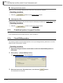
Utilize specified channel data to another channel.
Section 2.1.3
Auto Device Assignment
Assign sequential devices to the items selected for auto
refresh.
Section 2.1.2
APPENDIX
Edit (temperature input module)
Channel Copy
I
Automatic Adjustment for Height
Automatically adjust the height of intelligent function module
data table.
Automatic Adjustment for Width
Automatically adjust the width of intelligent function module
data table.
Tool (temperature input module)
Offset/Gain Setting
Data Initialization
Section 2.1.2
Reference
−
Intelligent Function Module Tool
Temperature Input Module
Reference
INDEX
View (temperature input module)
−
−
Set an offset/gain of temperature input module.
Section 3.2.1
Initialize the set data of specified channel.
Section 2.1.4
1.4.2 List of functions for analog module
1 - 11
GX Works2
1 OVERVIEW
1.4.4
List of functions for temperature control module
The following tables show the functions for temperature control module.
Edit (temperature control module)
Reference
Channel Copy
Utilize specified channel data to another channel.
Section 2.1.3
Auto Device Assignment
Assign sequential devices to the items selected for auto
refresh.
Section 2.1.2
View (temperature control module)
Automatic Adjustment for Height
Automatically adjust the height of intelligent function module
data table.
Automatic Adjustment for Width
Automatically adjust the width of intelligent function module
data table.
Tool (temperature control module)
Reference
−
−
Auto Tuning
Execute the Auto tuning function of temperature control
module.
Section 3.3.1
Sensor Correction
Execute the Sensor Correction function of the temperature
control module.
Section 3.3.2
Initialize the set data of specified channel.
Section 2.1.4
Data Initialization
1.4.5
Section 2.1.2
−
Intelligent Function Module Tool
Temperature Control Module
Reference
List of functions for counter module
The following tables show the functions for counter module.
Edit (counter module)
Utilize specified channel data to another channel.
Section 2.1.3
Auto Device Assignment
Assign sequential devices to the items selected for auto
refresh.
Section 2.1.2
View (counter module)
Automatic Adjustment for Height
Automatically adjust the height of intelligent function module
data table.
Automatic Adjustment for Width
Automatically adjust the width of intelligent function module
data table.
Tool (counter module)
Counter Module
Preset
Data Initialization
Reference
Section 2.1.2
Reference
−
Intelligent Function Module Tool
1 - 12
Reference
Channel Copy
−
−
Execute the Preset function of counter module.
Section 3.4.1
Initialize the set data of specified channel.
Section 2.1.4
1.4.4 List of functions for temperature control module
1.4 List of Functions
The following tables show the functions for QD75/LD75 positioning module.
−
−
Open Other Data
Import GX Configurator-QP Data
Read the data created with GX Configurator-QP, and add a
new positioning module.
Edit for Parameter (QD75/LD75 positioning module)
Set Maximum Value
Set the maximum value to the specified parameter item.
Set Minimum Value
Set the minimum value to the specified parameter item.
Set Default Value
Set the default to the specified parameter item.
Computation of Electronic Gear
Calculate the electronic gear from the data set on the
parameter screen.
Axis Copy
Utilize the specified axis data to another axis.
Edit for Servo Parameter (QD75/LD75 positioning module)
Set Maximum Value
Set the maximum value to the specified servo parameter
item.
Set Minimum Value
Set the minimum value to the specified servo parameter
item.
Set Default Value
Set the default to the specified servo parameter item.
Axis Copy
Utilize the specified axis data to another axis.
Edit for Positioning Data (QD75/LD75 positioning module)
Select All
Select all items.
Jump
Jump to the specified positioning data number.
Initialization of Row
Initialize the row at the cursor position.
Initialization of Column
Initialize the column at the cursor position.
Insert Row
Add a row above the cursor position.
Delete Row
Delete a row at the cursor position.
Positioning Data Copy
Copy the data in the row at the cursor position.
Positioning Data Paste
Paste the data to the row at the cursor position.
Axis Copy
Utilize specified axis data to another axis.
M Code Comment Edit
Edit the M code comment.
Condition Data Edit
Edit the condition data.
1.4.6 List of functions for QD75/LD75 positioning module
Section 3.5.8
Reference
Section 3.5.6
Section 2.1.3
Reference
Section 3.5.6
Section 2.1.3
Reference
COMMON OPERATIONS
FOR INTELLIGENT
FUNCTION MODULES
Read data from the positioning module and reflect it to the
positioning module selected on the Project view.
2
Section 3.5.7
3
OPERATING
INTELLIGENT
FUNCTION MODULES
Read from the Positioning Module
Data
Save data of the positioning module selected on the Project
view to a file.
4
PREDEFINED
PROTOCOL SUPPORT
FUNCTION
Save the Positioning Module Data
Reference
A
APPENDIX
Project (QD75/LD75 positioning module)
Intelligent Function Module
OVERVIEW
1
List of functions for QD75/LD75 positioning module
I
Section 3.5.6
Section 2.1.3
Section 3.5.6
1 - 13
INDEX
1.4.6
GX Works2
1 OVERVIEW
Edit for Block Starting (QD75/LD75 positioning module)
Select All
Select all items.
Jump
Jump to the specified positioning data number.
Initialization of Row
Initialize the row at the cursor position.
Initialization of Column
Initialize the column at the cursor position.
Insert Row
Add a row above the cursor position.
Delete Row
Delete a row at the cursor position.
Axis Copy
Utilize specified axis data to another axis.
Block Start Copy
Utilize specified block start data to another block start data.
Condition Data Edit
Edit the condition data.
Edit for Auto Refresh (QD75/LD75 positioning module)
Assign sequential devices to the items selected for auto
refresh.
Auto Device Assignment
View (QD75/LD75 positioning module)
Automatic Adjustment for Height
Automatically adjust the height of intelligent function module
data table.
Automatic Adjustment for Width
Automatically adjust the width of intelligent function module
data table.
Tool (QD75/LD75 positioning module)
1 - 14
Section 3.5.6
Section 2.1.3
Section 3.5.6
Reference
Section 2.1.2
Reference
Section 2.1.2
Reference
−
Intelligent Function Module Tool
QD75/LD75 Positioning Module
Reference
−
−
Positioning Monitor
Execute the positioning monitor.
Section 3.5.1
Positioning Test
Execute the positioning test.
Section 3.5.2
Wave Trace
Execute the wave trace.
Section 3.5.3
Location Trace
Execute the location trace.
Section 3.5.4
Data Initialization
Initialize the set data of specified axis.
Section 2.1.4
Request of Parameter Initialization/Flash
ROM Write Request
Request a command to write buffer memory data of QD75/
LD75 positioning module to the flash ROM.
Section 3.5.5
Offline Simulation
Simulate the waveform and location of set positioning data
offline.
Automatic Command Speed Calculation
Calculate the constant speed of traveling time between the
start position and the target position.
Automatic Sub Arc Calculation
Calculate the positioning data of circular interpolation control
to form a smooth arc (curve line) from the angle position
created by two continuous linear interpolation controls.
1.4.6 List of functions for QD75/LD75 positioning module
Section 3.5.6
1.4 List of Functions
Edit (QD70 positioning module)
Reference
Initialization of Row
Initialize the row at the cursor position.
Initialization of Column
Initialize the column at the cursor position.
Axis Copy
Utilize specified axis data to another axis.
Section 2.1.3
Auto Device Assignment
Assign sequential devices to the items selected for auto
refresh.
Section 2.1.2
View (QD70 positioning module)
Automatic Adjustment for Height
Automatic Adjustment for Width
Automatically adjust the height of intelligent function module
data table.
Automatically adjust the width of intelligent function module
data table.
Tool (QD70 positioning module)
Data Initialization
Initialize the set data of specified axis.
Section 3.5.6
Reference
Section 2.1.2
Reference
Section 2.1.4
2
COMMON OPERATIONS
FOR INTELLIGENT
FUNCTION MODULES
The following tables show the functions for QD70 positioning module.
OVERVIEW
1
List of functions for QD70 positioning module
3
OPERATING
INTELLIGENT
FUNCTION MODULES
1.4.7
List of functions for simple motion module
The following tables show the functions for simple motion module.
Edit (simple motion module)
Auto Device Assignment
Assign sequential devices to the items selected for auto
refresh.
View (simple motion module)
Automatic Adjustment for Height
Automatically adjust the height of auto refresh data table.
Automatic Adjustment for Width
Automatically adjust the width of auto refresh data table.
Tool (simple motion module)
Initialize the auto refresh data of specified axis.
Section 2.1.2
Reference
Section 2.1.2
A
I
Reference
Section 2.1.4
INDEX
Data Initialization
Reference
APPENDIX
1.4.8
PREDEFINED
PROTOCOL SUPPORT
FUNCTION
4
1.4.7 List of functions for QD70 positioning module
1 - 15
GX Works2
1 OVERVIEW
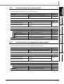
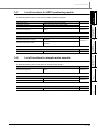
1.4.9
List of functions for serial communication/modem interface
module
The following tables show the functions for serial communication/modem interface module.
Edit (serial communication/modem interface module)
Reference
Channel Copy
Utilize specified channel data to another channel.
Section 2.1.3
Auto Device Assignment
Assign sequential devices to the items selected for auto
refresh.
Section 2.1.2
View (serial communication/modem interface module)
String/Hexadecimal Switch Format
Switch between the string display and the hexadecimal
display on the User Register Frame Content screen.
Automatic Adjustment for Height
Automatically adjust the height of intelligent function module
data table.
Automatic Adjustment for Width
Automatically adjust the width of intelligent function module
data table.
Tool (serial communication/modem interface module)
Section 2.1.2
Reference
−
Intelligent Function Module Tool
Serial Communication Module
Reference
−
Circuit Trace
Execute the circuit trace.
Predefined Protocol Support
Function
Start the predefined protocol support function.
−
Section 3.7.2
Chapter 4
Data Initialization
Initialize the set data of specified channel.
Section 2.1.4
Flash ROM Operation
Execute the flash ROM write permission/protection, module
initialization, and flash ROM write command of serial
communication module.
Section 3.7.4
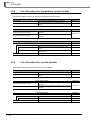
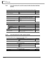
1.4.10
List of functions for AS-i master module
The following tables show the functions for AS-i master module.
Edit (AS-i master module)
Auto Device Assignment
Assign sequential devices to the items selected for auto
refresh.
View (AS-i master module)
Automatic Adjustment for Height
Automatically adjust the height of intelligent function module
data table.
Automatic Adjustment for Width
Automatically adjust the width of intelligent function module
data table.
Tool (AS-i master module)
Data Initialization
1 - 16
Initialize the set data of specified channel.
1.4.9 List of functions for serial communication/modem interface module
Reference
Section 2.1.2
Reference
Section 2.1.2
Reference
Section 2.1.4
1.4 List of Functions
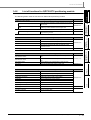
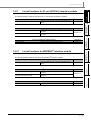
Auto Device Assignment
View (FL-net (OPCN-2) interface module)
Automatic Adjustment for Height
Automatically adjust the height of intelligent function module
data table.
Automatic Adjustment for Width
Automatically adjust the width of intelligent function module
data table.
Tool (FL-net (OPCN-2) interface module)
Data Initialization
1.4.12
Initialize the set data of specified channel.
Reference
Section 2.1.2
Reference
Section 2.1.2
3
Reference
Section 2.1.4
4
®
List of functions for MODBUS interface module
The following tables show the functions for MODBUS® interface module.
Edit (MODBUS® interface module)
Auto Device Assignment
Assign sequential devices to the items selected for auto
refresh.
View (MODBUS® interface module)
Automatic Adjustment for Height
Automatically adjust the height of intelligent function module
data table.
Automatic Adjustment for Width
Automatically adjust the width of intelligent function module
data table.
Tool (MODBUS® interface module)
Initialize the specified set data.
Reference
Section 2.1.2
Reference
Section 2.1.2
A
I
Reference
Section 2.1.4
INDEX
Data Initialization
2
OPERATING
INTELLIGENT
FUNCTION MODULES
Assign sequential devices to the items selected for auto
refresh.
PREDEFINED
PROTOCOL SUPPORT
FUNCTION
Edit (FL-net (OPCN-2) interface module)
COMMON OPERATIONS
FOR INTELLIGENT
FUNCTION MODULES
The following tables show the functions for FL-net (OPCN-2) interface module.
OVERVIEW
1
List of functions for FL-net (OPCN-2) interface module
APPENDIX
1.4.11
1.4.11 List of functions for FL-net (OPCN-2) interface module
1 - 17
GX Works2
1 OVERVIEW
MEMO
1 - 18
1.4.12 List of functions for MODBUS® interface module
COMMON OPERATIONS
FOR INTELLIGENT
FUNCTION MODULES
COMMON OPERATIONS
FOR INTELLIGENT
FUNCTION MODULES
2
This chapter explains common operations for the intelligent function modules, such as adding a new project,
setting the parameters, and etc.
4
PREDEFINED
PROTOCOL SUPPORT
FUNCTION
Operations of Intelligent Function Module Data. . . . . . . . . . . 2-2
Utilizing Sample Comments of Intelligent Function Module . . . . . 2-21
Writing/Reading Intelligent Function Module Data . . . . . . . . . . . . 2-21
Monitoring Intelligent Function Modules . . . . . . . . . . . . . . . . . . . 2-22
APPENDIX
A
I
INDEX
2.1
2.2
2.3
2.4
3
OPERATING
INTELLIGENT
FUNCTION MODULES
2
OVERVIEW
1
2-1
GX Works2
2 COMMON OPERATIONS FOR INTELLIGENT FUNCTION MODULES
2.1
Operations of Intelligent Function Module Data
This section explains how to set the intelligent function module data.
Adding an intelligent function module to a project, the data settings (parameter and switch settings) of the
intelligent function module become available.
2.1.1
Adding intelligent function module data
Add the intelligent function module data to the project being edited.
The installation slot number and start XY address of the added intelligent function module are reflected
to the I/O assignment setting of the PLC parameter.
Screen display
Select [Project] ⇒ [Intelligent Function Module] ⇒ [Add New Module].
< QCPU (Q mode) >
< LCPU >
Occupied I/O
points information
Occupied I/O
points information
Operating procedure
1.
Set the items on the screen.
Item
Module Selection
Module Type
Select the type of the intelligent function module to be added.
Module Name
Select the model of the intelligent function module to be added.
−
Mount Position
Base No.
*1
Set the slot number of the intelligent function module.
Specify start XY address
Set the start XY address of the intelligent function module.
Occupied I/O points
information
For QCPU (Q mode), displays the number of occupied slots and the number of
occupied I/O points of the module selected for "Module Name".
For LCPU, displays the number of logically-occupied modules and the number of
occupied I/O points of the module selected for "Module Name".
Title
2-2
Specify the base number where the intelligent function module is mounted.
Mounted Slot No.
Title Setting
*1 :
Description
−
−
Set the title.
(The number of applicable characters is 32)
QCPU (Q mode) only
2.1.1 Adding intelligent function module data
2.1 Operations of Intelligent Function Module Data
2.
Click the
1
button.
OVERVIEW
The specified intelligent function module data
are added to the Project view.
Screen button
●
Operation
1. Select the line of the mounting position for
the intelligent function module to be added.
2. Click the
3
OPERATING
INTELLIGENT
FUNCTION MODULES
Displays the Acknowledge I/O Assignment screen. On the Acknowledge I/O Assignment screen,
the current I/O assignment settings can be checked. The mounting position for the intelligent
function module to be added can also be set.
The following explains how to set the mounting position.
COMMON OPERATIONS
FOR INTELLIGENT
FUNCTION MODULES
2
button.
4
PREDEFINED
PROTOCOL SUPPORT
FUNCTION
The selected mounting position is set on the
New Module screen.
APPENDIX
A
INDEX
I
2.1.1 Adding intelligent function module data
2-3
GX Works2
2 COMMON OPERATIONS FOR INTELLIGENT FUNCTION MODULES
● Switch setting
The switch setting of the intelligent function module is reflected to the "Switch Setting" on the <<I/O Assignment>>
tab of the PLC parameter.
● Changing the positioning data display range
The display range of the positioning data can be changed by the following setting.
Select [Tool] ⇒ [Options] ⇒ "Intelligent Function Module" ⇒ "QD75/LD75 Type Positioning", and make settings for
"Display Specification of Positioning Data".
If the display range is enlarged by setting "Display specification of positioning data", it takes longer time to display
the positioning data editing window.
When positioning data No.101 and above are not necessary, select "Data No.1 to 100".
● Display when mismatches of data assignment exist between PLC parameters and intelligent function
module data
When mismatches of data assignment exist between the I/O assignment setting of the PLC parameter and the
intelligent function module data, the icon in the Project view is displayed as shown below.
<Normal display>
<Duplicate display>
● Opening project data which contain modules not supported by this version
When project data which contain an intelligent function module not supported by this version are opened,
"Reserved Module" is displayed in the tree of the Project view.
It cannot be edited, displayed, or printed, however, it can be saved in the project. In addition, its intelligent function
module parameters can be written to the programmable controller CPU.
(Example of display in the Project view)
2-4
2.1.1 Adding intelligent function module data
2.1 Operations of Intelligent Function Module Data
1
Setting intelligent function module data
OVERVIEW
Edit the intelligent function module data.
Screen display
Select Project view ⇒ "Intelligent Function Module" ⇒ "(module)" ⇒ "(intelligent function module data)".
The screen image below is an example when the data of QJ71C24N is selected.
2
COMMON OPERATIONS
FOR INTELLIGENT
FUNCTION MODULES
2.1.2
OPERATING
INTELLIGENT
FUNCTION MODULES
3
PREDEFINED
PROTOCOL SUPPORT
FUNCTION
4
Set the items on the screen.
For details of the setting items, refer to the manuals of each intelligent function module.
• Detailed explanation of a setting item is displayed at the bottom of the screen when it is selected.
For LD75 positioning module, a detailed explanation is displayed on the Intelligent Function
Module Guidance window. (
Section 3.5.6)
• For a multiple-choice item, the available choices can be displayed in a combo box by doubleclicking the cell.
• For a text input item, the cell becomes editable by double-clicking it.
• "Display Filter" filters the settings so that only those related to the selected item are displayed.
• For Q64TCTTN/Q64TCTTBWN/Q64TCRTN/Q64TCRTBWN/L60TCTT4/L60TCTT4BW/
L60TCRT4/L60TCRT4BW, "Control Mode" set on the Switch Setting is displayed.
Click the
Setting to '0'.
button to set the unnecessary items for the mode set on the Switch
2.1.2 Setting intelligent function module data
2-5
A
APPENDIX
•
I
INDEX
Operating procedure
GX Works2
2 COMMON OPERATIONS FOR INTELLIGENT FUNCTION MODULES
● Adjusting height/width of data table when characters are illegible
Height and width of cells can be adjusted by selecting [View] ⇒ [Automatic Adjustment for Height]/[Automatic
Adjustment for Width].
The adjusted height and width are saved to the project.
[View]
[Automatic Adjustment
for Height]
● Switching display on the setting screen of serial communication module.
The display can be switched to either string or hexadecimal format by selecting [View] ⇒ [String/Hexadecimal
Switch Format] on the User Register Frame Content screen.
■
Switch settings
Edit the switch setting of the intelligent function module.
Screen display
Select Project view ⇒ "Intelligent Function Module" ⇒ "(module)" ⇒ "Switch Setting".
Operating procedure
1.
Set the items on the screen
For details of the setting items, refer to the manual of each intelligent function module.
• The available choices can be displayed in a combo box by double-clicking the cell.
2.
Click the
button
This setting is applied to the switch setting on the <<I/O Assignment>> tab of the PLC parameter.
The switch setting set on the <<I/O Assignment>> tab of the PLC parameter is also applied to this
setting.
● Switch setting data not supported by this version
To set the switch setting data not supported by this version, do it in the switch setting under <<I/O assignment>> in
the PLC parameter.
2-6
2.1.2 Setting intelligent function module data
2.1 Operations of Intelligent Function Module Data
■
1
Auto refresh function
Set the auto refresh function of the intelligent function module.
OVERVIEW
Screen display
Select Project view ⇒ "Intelligent Function Module" ⇒ "(module)" ⇒ "Auto Refresh".
COMMON OPERATIONS
FOR INTELLIGENT
FUNCTION MODULES
2
OPERATING
INTELLIGENT
FUNCTION MODULES
3
For details of the setting items, refer to the manual of each intelligent function module.
• Detailed explanation of a setting item is displayed at the bottom of the screen when it is selected.
For LD75 positioning module, a detailed explanation is displayed on the Intelligent Function
Module Guidance window. (
Section 3.5.6)
• For Structured projects, device format and address format can be switched by selecting "Device
Program Display Mode".
• "Display Filter" filters the settings so that only those related to the selected item are displayed.
• For the items of which the offset values of buffer memory and the transfer word counts can be
changed, set the items such as auto refresh devices in another screen.
Example) Setting screens of AS-i master module and FL-net (OPCN-2) interface module
<AS-i master module>
< FL-net (OPCN-2) interface module >
A
APPENDIX
Setting devices
I
INDEX
•
PREDEFINED
PROTOCOL SUPPORT
FUNCTION
4
Operating procedure
2.1.2 Setting intelligent function module data
2-7
GX Works2
2 COMMON OPERATIONS FOR INTELLIGENT FUNCTION MODULES
● Contents displayed in explanation field
The following shows the contents displayed in the explanation field.
Item
Transfer
Direction
Description
Intelligent Function
Module → PLC
Transfers the buffer memory data of the intelligent function module to the
specified device of the programmable controller CPU.
PLC → Intelligent
Function Module
Transfers the specified device data of the programmable controller CPU to the
buffer memory of the intelligent function module.
Buffer Memory Address
Displays the buffer memory address of the item to be auto refreshed.
Offset
Displays the offset value according to the target buffer memory address.
Transfer Word Counts
Displays the transfer word counts of the item to be auto refreshed.
Maximum Transfer Word Counts
Displays the maximum transfer word counts of the item to be auto refreshed.
Device Comment
Displays the device comment that is set to the selected device.
● Items of which offset values of buffer memory and transfer word counts can be changed
The set value of the items of which the offset values of buffer memory and the transfer word counts can be
changed, is displayed as shown below.
Device number (offset value,
transfer word counts)
● Assigning sequential devices for auto refresh
The following screen is displayed by selecting [Edit] ⇒ [Auto Device Assignment] after selecting cells to assign
sequential devices. Devices are assigned sequentially from the one specified.
● Display of the Project view when the devices set in the auto refresh setting are duplicated in the module
When the screen is closed while the duplicated devices of the auto refresh setting exist, the icon in the Project view
is displayed as shown below. To check the device duplications in multiple intelligent function modules, select [Tool]
⇒ [Check Intelligent Function Module Parameter] ⇒ [Check Auto Refresh Duplication].
<Normal display>
2-8
2.1.2 Setting intelligent function module data
<Display when duplication occurs>
2.1 Operations of Intelligent Function Module Data
On the data setting screen of an intelligent function module, the setting status is identified by colors as
shown below.
2.1.3
Setting status
Background
Blue
White
Default values
Black
White
Values other than default values
White
Red
Red
White
Black
Gray
2
Items whose values outside the setting range
Items for which device is duplicated in auto refresh setting.
Items for which setting is not required.
Yellow
Green
White
Comments (Positioning module only)
Blue
Gray
Item with the transfer direction of [Intelligent Function Module → PLC]
Green
Gray
Item with the transfer direction of [PLC → Intelligent Function Module]
Channel copy/axis copy
4
Utilize specified channel/axis data to another channel/axis data when setting intelligent function module
data.
The Channel copy function is not supported by the Auto refresh function.
A
Operating procedure
1.
3
OPERATING
INTELLIGENT
FUNCTION MODULES
Black
Items for which setting (partner axis) is not required at the data number specified for axis
to be interpolated.
(QD75/LD75 positioning module only)
COMMON OPERATIONS
FOR INTELLIGENT
FUNCTION MODULES
Color
Text
OVERVIEW
1
Data setting screen of intelligent function modules
PREDEFINED
PROTOCOL SUPPORT
FUNCTION
■
Select [Edit] ⇒ [Channel Copy]/[Axis Copy].
APPENDIX
The Channel Copy screen is displayed.
The image below is a screen when the operation is performed on the data of Q68DAIN.
INDEX
I
2.
Select the copy target channel/axis and data, and click the
button.
The channel/axis data are copied.
2.1.3 Channel copy/axis copy
2-9
GX Works2
2 COMMON OPERATIONS FOR INTELLIGENT FUNCTION MODULES
2.1.4
Data initialization
Initialize the set data of intelligent function module.
For LD77MH4, LD77MH16, only the auto refresh data are initialized.
Operating procedure
1.
Select [Tool] ⇒ [Data Initialization].
The Data Initialization screen is displayed.
The image below is a screen when the operation is performed with the data of Q68DAIN.
2.
Select the target channel(s) whose data to be initialized, and click the
button.
The data of selected channel(s) are initialized.
2.1.5
Deleting intelligent function modules
Delete an intelligent function module from the project being edited.
Operating procedure
1.
Select the intelligent function module to be deleted from the Project view.
2.
Select [Project] ⇒ [Intelligent Function Module] ⇒ [Delete Module].
The selected intelligent function module is deleted.
2 - 10
2.1.4 Data initialization
2.1 Operations of Intelligent Function Module Data
1
Displaying properties of intelligent function modules
Check the setting information of an intelligent function module. This operation can also change the
installation slot number, start XY address, module name, and title.
OVERVIEW
2.1.6
2
Screen display
COMMON OPERATIONS
FOR INTELLIGENT
FUNCTION MODULES
Select [Project] ⇒ [Intelligent Function Module] ⇒ [Property].
OPERATING
INTELLIGENT
FUNCTION MODULES
3
Occupied I/O
points information
4
Set the items on the screen.
Item
Module Selection
Module Type
Display the type of the intelligent function module.
Module Name
Display the model of the intelligent function module.
Base No.
*1
Display the base number where the intelligent function module is mounted.
Mounted Slot No.
Display the current slot number.
Specify Start XY Address
Display the current start XY address.
Occupied I/O points
information
For QCPU (Q mode), display the number of occupied slots and the number of
occupied I/O points of the module selected for "Module Name".
For LCPU, display the number of logically-occupied modules and the number of
occupied I/O points of the module selected for "Module Name".
Title
I
−
Display the current title.
(The number of applicable characters is 32)
INDEX
Title Setting
2.
A
−
Mount Position
*1 :
Description
−
APPENDIX
1.
PREDEFINED
PROTOCOL SUPPORT
FUNCTION
Operating procedure
QCPU (Q mode) only
Click the
button.
Screen button
For the buttons on the screen, refer to Section 2.1.1.
2.1.6 Displaying properties of intelligent function modules
2 - 11
GX Works2
2 COMMON OPERATIONS FOR INTELLIGENT FUNCTION MODULES
2.1.7
Checking/changing the number of settable intelligent
function module parameters
Display a list of the intelligent function module parameters (initial setting/auto refresh) set to the current
project.
Set for enabling/disabling initial setting and auto refresh as intelligent function module parameters.
■
Enabling/disabling intelligent function module parameters
Set for enabling/disabling initial setting and auto refresh as intelligent function module parameters.
Since a programmable controller CPU limits the number of parameters that can be set for the mounted
intelligent function modules, check the number of settable parameters using this function and switch
enabling/disabling for the parameters so that the number of set parameters is within the allowable
range.
For the number of settable parameters, refer to the manual of each intelligent function module.
Screen display
Select [Project] ⇒ [Intelligent Function Module] ⇒ [Intelligent Function Module Parameter List].
2 - 12
2.1.7 Checking/changing the number of settable intelligent function module parameters
2.1 Operations of Intelligent Function Module Data
1
Operating procedure
Description
Display the model of the target intelligent function module.
Initialization (Count)
Select whether to enable/disable initial setting.
Uncheck the item if it is not set as an intelligent function module parameter.
For a module that has no initial setting, "-" is displayed.
Auto Refresh (Count)
Select whether to enable/disable auto refresh.
Uncheck the item if it is not set as an intelligent function module parameter.
For a module for which auto refresh is not set, "No setting" is displayed.
Intelligent Function Module
Parameter Setting Count Total
Display the number of settable intelligent function module parameters.
2.
2
COMMON OPERATIONS
FOR INTELLIGENT
FUNCTION MODULES
Module Name
Initial
Display the number of initial settings set as intelligent function module parameters.
Auto Refresh
Display the number of auto refreshes set as intelligent function module parameters.
Click the
button.
● When the initial setting and the number of auto refresh settings cannot be changed
In case of the following conditions, the number of initial settings and auto refresh settings can not be changed.
Even when the "Setting Exist" is selected, the display is masked and the check box is not displayed.
• Reserved module
• The access authority for security is in the write-protected mode.
■
4
A
Intelligent function module parameters
When the intelligent function module data are set, intelligent function module parameters are created.
The intelligent function module parameters consist of initial setting and auto refresh.
The intelligent function module parameters, when written to a programmable controller CPU, operate
as explained below. Write the intelligent function module parameters to the programmable controller
CPU using the Write to PLC function. (
GX Works2 Version 1 Operating Manual (Common))
● Initial setting
The parameters of the individual intelligent function module data are set as initial setting data.
The initial setting data are registered to the programmable controller CPU parameters and
automatically written to the intelligent function module when the programmable controller CPU
turns to the RUN state.
● Auto refresh
If auto refresh is set to the buffer memory of an intelligent function module, data are write/read
automatically to/from the specified devices when the END instruction is executed in the
programmable controller CPU.
For the intelligent function module type and the availability of initial setting/auto refresh setting, refer to
Section 2.1.1.
2.1.7 Checking/changing the number of settable intelligent function module parameters
3
OPERATING
INTELLIGENT
FUNCTION MODULES
Display the start XY address of the target intelligent function module.
PREDEFINED
PROTOCOL SUPPORT
FUNCTION
XY Address
2 - 13
APPENDIX
Item
OVERVIEW
Set the items on the screen.
I
INDEX
1.
GX Works2
2 COMMON OPERATIONS FOR INTELLIGENT FUNCTION MODULES
■
Number of parameter settings for intelligent function modules
The number of parameter settings for intelligent function modules (initial setting and auto refresh) are
limited depending on the programmable controller CPUs or MELSECNET/H Remote I/O modules. In
addition, the number of parameter settings are also limited depending on the type of intelligent function
modules.
Be sure to set the total number of parameter settings of the intelligent function modules, not exceeding
the maximum number of parameter settings of the programmable controller CPUs or MELSECNET/H
Remote I/O modules.
● Limit for the number of parameter settings of the programmable controller CPUs or
MELSECNET/H Remote I/O modules
The following table shows the number of parameter settings for the initial setting and the auto
refresh that can be set on the programmable controller CPUs or MELSECNET/H Remote I/O
modules.
Application target of intelligent function module
QCPU (Q mode)
LCPU
2 - 14
Maximum number of parameter settings
Initial setting
Auto refresh
Basic model QCPU,
High Performance model QCPU,
MELSECNET/H Remote I/O module
512
256
Q00UJ, Q00U, Q01U, Q02U
2048
1024
Q03UD, Q03UDE, Q04UDH, Q04UDEH,
Q06UDH, Q06UDEH, Q10UDH, Q10UDEH,
Q13UDH, Q13UDEH, Q20UDH, Q20UDEH,
Q26UDH, Q26UDEH, Q50UDEH,
Q100UDEH
4096
2048
L02, L02-P
2048
1024
L26-BT, L26-PBT
4096
2048
2.1.7 Checking/changing the number of settable intelligent function module parameters
2.1 Operations of Intelligent Function Module Data
QCPU (Q mode)
Temperature input module
Temperature control
module
Counter module
2
13
Q68ADV
1
25
1
25
Q64AD-GH
5
27
Q62AD-DGH
9
15
Q68AD-G
7
36
Q66AD-DG
11
28
Q62DAN
1
5
Q64DAN
1
9
Q68DAVN
1
17
Q68DAIN
1
17
Q62DA
1
5
Q64DA
1
9
Q68DAV
1
17
Q68DAI
1
17
Q62DA-FG
4
9
Q66DA-G
5
14
Q64AD2DA
8
61
Q61LD
3
14
Q64RD
5
18
Q64RD-G
5
18
Q64TD
6
13
Q64TDV-GH
6
13
Q68TD-G-H02
6
24
Q68TD-G-H01
6
24
Q68RD3-G
6
24
Q64TCTT
21
61
Q64TCTTBW
21
73
Q64TCRT
21
61
Q64TCRTBW
21
73
Q64TCTTN
52
103
Q64TCTTBWN
53
115
Q64TCRTN
51
103
Q64TCRTBWN
52
115
Q62HLC
22
52
QD62
8
14
QD62D
8
14
QD62E
8
14
QD63P6
6
48
QD64D2
6
16
QD60P8-G
24
8
QD65PD2
18
62
2.1.7 Checking/changing the number of settable intelligent function module parameters
3
OPERATING
INTELLIGENT
FUNCTION MODULES
Q68ADI
2
4
PREDEFINED
PROTOCOL SUPPORT
FUNCTION
Analog module
Q64AD
Module model
A
APPENDIX
Module type
Auto refresh
(Maximum
number of
settings)
I
INDEX
CPU
Initial setting
(Fixed)
COMMON OPERATIONS
FOR INTELLIGENT
FUNCTION MODULES
The following table shows the number of parameter settings for the initial setting and auto refresh
that can be set on the intelligent function modules.
'-' in the Initial setting column indicates that the corresponding module does not have the initial
setting.
OVERVIEW
1
● Limit for the number of parameter settings of the intelligent function modules
2 - 15
GX Works2
2 COMMON OPERATIONS FOR INTELLIGENT FUNCTION MODULES
CPU
Module type
Module model
QD75P1
QD75 positioning module
QCPU (Q mode)
QD70 positioning module
Serial communication/
Modem interface module
AS-i master module
FL-net
(OPCN-2)
interface module
MODBUS®
Interface Module
2 - 16
Initial setting
(Fixed)
Auto refresh
(Maximum
number of
settings)
−
7
QD75P2
−
14
QD75P4
−
28
QD75P1N
−
7
QD75P2N
−
14
28
QD75P4N
−
QD75D1
−
7
QD75D2
−
14
QD75D4
−
28
QD75D1N
−
7
QD75D2N
−
14
QD75D4N
−
28
QD75M1
−
7
QD75M2
−
14
QD75M4
−
28
QD75MH1
−
7
QD75MH2
−
14
QD75MH4
−
28
QD70P4
12
26
QD70P8
24
50
QD70D4
16
26
QD70D8
32
50
QD72P3C3
12
18
QJ71C24N
−
46
QJ71C24N-R2
−
47
QJ71C24N-R4
−
46
QJ71C24
−
46
QJ71C24-R2
−
47
QJ71AS92
−
30
QJ71FL71-F01
2
14
QJ71FL71-T-F01
2
14
QJ71FL71-B2-F01
2
14
QJ71FL71-B5-F01
2
14
QJ71FL71
2
14
QJ71FL71-T
2
14
QJ71FL71-B2
2
14
QJ71FL71-B5
2
14
QJ71MT91
3
5
QJ71MB91
3
5
2.1.7 Checking/changing the number of settable intelligent function module parameters
2.1 Operations of Intelligent Function Module Data
Temperature control
module
LCPU
Counter module
LD75 positioning module
Simple motion module
Serial communication
module
L60AD4
12
75
L60DA4
4
11
L60TCTT4
43
103
L60TCTT4BW
43
115
L60TCRT4
43
103
L60TCRT4BW
43
115
LD62
8
14
LD62D
8
14
LD75P4
−
28
LD75D4
−
28
LD77MH4
−
28
LD77MH16
−
112
LJ71C24
−
50
LJ71C24-R2
−
51
OVERVIEW
Analog module
Module model
1
2
COMMON OPERATIONS
FOR INTELLIGENT
FUNCTION MODULES
Module type
Auto refresh
(Maximum
number of
settings)
3
OPERATING
INTELLIGENT
FUNCTION MODULES
CPU
Initial setting
(Fixed)
4
PREDEFINED
PROTOCOL SUPPORT
FUNCTION
● Number of auto refresh settings
The number of auto refresh settings in which devices are set is counted.
In the following settings, the number of auto refresh settings is 8.
APPENDIX
A
INDEX
I
2.1.7 Checking/changing the number of settable intelligent function module parameters
2 - 17
GX Works2
2 COMMON OPERATIONS FOR INTELLIGENT FUNCTION MODULES
2.1.8
Checking device duplication of auto refresh setting
Check the device duplication of auto refresh settings among intelligent function modules.
Screen display
Select [Tool] ⇒ [Check Intelligent Function Module Parameter] ⇒ [Check Auto Refresh Duplication].
Operating procedure
1.
Select the modules to check the device duplication of auto refresh settings.
2.
Click the
button.
If device duplication is found, the check result is displayed in the Output window.
By double-clicking the result, the corresponding error location in the program is displayed.
● When the device duplication of auto refresh settings can not be checked
In case of the following conditions, the module is recognized as a module that cannot check the device duplication
of auto refresh settings, and "Cannot Select" is displayed.
• No device is set on the Auto Refresh screen.
• Not checked in the intelligent function module parameter list.
• The module start XY address is not set.
• Reserved module
• The access authority for security is in the read-protected mode.
2 - 18
2.1.8 Checking device duplication of auto refresh setting
2.1 Operations of Intelligent Function Module Data
The following explains the operating procedure to change intelligent function module type, for instance,
from QD75P4 to QD75D4, or from LD75D4 to LD75P4.
The intelligent function module type can be changed by copying and pasting the original data onto the
parameter setting screen of the new module data.
The following operating procedure is the instance when changing the type from QD75P4 to QD75D4.
Operating procedure
1.
Add new intelligent function
Section 2.1.1)
module data. (
OVERVIEW
1
Changing intelligent function module type
2
COMMON OPERATIONS
FOR INTELLIGENT
FUNCTION MODULES
2.1.9
Add a new module.
Display both parameter setting screens of the original module and the new module.
4
PREDEFINED
PROTOCOL SUPPORT
FUNCTION
2.
OPERATING
INTELLIGENT
FUNCTION MODULES
3
APPENDIX
A
3.
On the parameter setting screen of the original module, right-click the top left cell
and select [Copy] from the shortcut menu to copy all data.
2.1.9 Changing intelligent function module type
2 - 19
INDEX
I
GX Works2
2 COMMON OPERATIONS FOR INTELLIGENT FUNCTION MODULES
4.
2 - 20
On the parameter setting screen of the new module, right-click the top left cell and
select [Paste] from the shortcut menu to paste all data.
2.1.9 Changing intelligent function module type
2.2 Utilizing Sample Comments of Intelligent Function Module
2.2
Utilizing Sample Comments of Intelligent Function Module
OVERVIEW
Utilize sample comments of intelligent function module devices for device comments.
For details of the operation method, refer to the following manual.
1
GX Works2 Version 1 Operating Manual (Common)
2.3
Writing/Reading Intelligent Function Module Data
Write the set intelligent function module data to the programmable controller CPU, or the buffer memory and
flash ROM of the intelligent function module.
For details of the operation method, refer to the following manual.
3
OPERATING
INTELLIGENT
FUNCTION MODULES
GX Works2 Version 1 Operating Manual (Common)
COMMON OPERATIONS
FOR INTELLIGENT
FUNCTION MODULES
2
PREDEFINED
PROTOCOL SUPPORT
FUNCTION
4
APPENDIX
A
INDEX
I
2 - 21
GX Works2
2 COMMON OPERATIONS FOR INTELLIGENT FUNCTION MODULES
2.4
Monitoring Intelligent Function Modules
This section explains how to monitor input/output signals and buffer memory of an intelligent function module.
For QD75/LD75 positioning module, this function is used to debug a program such as ladder. For checking an
operation of QD75/LD75 positioning module or debugging, use the positioning monitor.
(
Section 3.5.1)
2.4.1
Registering and monitoring intelligent function modules
Register and monitor module information of an intelligent function module.
Screen display
Select [View] ⇒ [Docking Window] ⇒ [Intelligent Function Module Monitor] ⇒ [Intelligent Function Module
Monitor 1] to [Intelligent Function Module Monitor 10].
Display contents
Item
Description
Display the name of the module information.
Item
When "Data Type" is 'Detail Dialog' (
the head of each item.
)/'Error Code' or 'Warning Code' (
), an icon is displayed at
Current value
Display the current value of the module information.
Display character strings such as ON/OFF.
Device
Display the device assigned to the module information.
Data Type
Display the data type of the module information.
For 'Detail Dialog'/'Error Code'/'Warning Code', details of each item can be confirmed.
For details, refer to the Point in this section.
Operating procedure
1.
Register the intelligent function module to be monitored.
For the registration method, refer to Section 2.4.2.
2.
Select [Online] ⇒ [Watch] ⇒ [Start Watching].
The current values of the registered intelligent function module are displayed in the window.
2 - 22
2.4.1 Registering and monitoring intelligent function modules
2.4 Monitoring Intelligent Function Modules
1
Customizing monitoring items
OVERVIEW
The module information registered to the Intelligent Function Module Monitor window can be
customized by cutting/copying/pasting/deleting unnecessary items.
The customized settings are saved along with the project.
Note that the operations to 'undo' the customized items cannot be performed.
2
Operating procedure
•
Select unnecessary items on the Intelligent Function Module Monitor window, right-click
them and select [Cut]/[Copy]/[Paste]/[Delete] from the shortcut menu.
COMMON OPERATIONS
FOR INTELLIGENT
FUNCTION MODULES
■
OPERATING
INTELLIGENT
FUNCTION MODULES
3
PREDEFINED
PROTOCOL SUPPORT
FUNCTION
4
I
INDEX
● Paste
The cut/copied items can be pasted in the same project in the same window only.
● Project created in former version
If a project to which the Intelligent Function Module Monitor is registered in GX Works2 Version 1.08J or earlier is
opened in GX Works2 Version 1.53F or later, all registered module information is discarded.
● Changing current value
The current value can be changed by directly inputting the desired value in "Current value" area during monitoring.
When the current value to be changed is displayed in character strings such as ON/OFF, available choices are
shown in a combo box. The current value cannot be changed is displayed in gray background.
APPENDIX
A
2.4.1 Registering and monitoring intelligent function modules
2 - 23
GX Works2
2 COMMON OPERATIONS FOR INTELLIGENT FUNCTION MODULES
● Detailed display of history information
For the analog module, QD75/LD75 type positioning module, and FL-net (OPCN-2) interface module, details of the
history information can be displayed during the monitoring.
To display details of the history information, double-click a row in which 'Detail Dialog' is displayed in the "Data
Type" column, or right-click it and select [Detail Dialog] from the shortcut menu.
The following shows the Detail Dialog screen for QD75P4.
● Detailed display of error code/warning code
Details of the error code/warning code can be displayed from the intelligent function module monitor windows or
the Detail Dialog.
To display details of the error code/warning code, double-click a row in which an error code/warning code is
displayed, or right-click it and select [Detail Display] from the shortcut menu.
The following shows the Detail Display screen of error code for QD75P4.
● Using multiple Intelligent Function Module Monitor windows
Each axis of positioning module can be monitored by activating multiple Intelligent Function Module Monitor
windows and customizing the settings of each window.
For Axis #1
2 - 24
For Axis #2
2.4.1 Registering and monitoring intelligent function modules
For Axis #3
For Axis #4
2.4 Monitoring Intelligent Function Modules
Register an intelligent function module to the Intelligent Function Module Monitor window.
■
Registering intelligent function modules using shortcut menu from Project view
Register an intelligent function module using the shortcut menu from the Project view.
Operation
1. Select a module to be registered to the Intelligent Function Module Monitor window from the
Project view.
2. Right-click and select [Register to Intelligent Function Module Monitor] in the shortcut menu.
2
3
OPERATING
INTELLIGENT
FUNCTION MODULES
The module is registered to the Intelligent Function Module Monitor window.
OVERVIEW
1
Registering intelligent function modules
COMMON OPERATIONS
FOR INTELLIGENT
FUNCTION MODULES
2.4.2
PREDEFINED
PROTOCOL SUPPORT
FUNCTION
4
■
A
Registering intelligent function modules using drag-and-drop operation
Register an intelligent function module using the drag-and-drop operation from the Project view.
APPENDIX
Operation
1. Select a module to be registered from the Project view.
2. Drag and drop it to the Intelligent Function Module Monitor window.
I
INDEX
The module is registered.
Drag and drop
2.4.2 Registering intelligent function modules
2 - 25
GX Works2
2 COMMON OPERATIONS FOR INTELLIGENT FUNCTION MODULES
■
Registering intelligent function modules using shortcut menu from Intelligent
Function Module Monitor window
Register an intelligent function module using the shortcut menu from the Intelligent Function Module
Monitor screen.
Operation
1. Right-click on the Intelligent Function Module Monitor window and select [Register Module
Information] from the shortcut menu.
The Module Information Selection screen is displayed.
2. Select a module to be registered from "Module List" and click the
button.
The module is registered to the Intelligent Function Module Monitor window.
When selecting the positioning module, AS-i master module, or FL-net (OPCN-2) interface
module in "Module List", select an item displayed in "Monitor Item Category List".
Example) AS-i master module
● Customizing monitoring items
The registered intelligent function module information can be customized by right-clicking the desired module
information on the Intelligent Function Module Monitor window and selecting [Cut]/[Copy]/[Paste]/[Delete] in the
shortcut menu. (
Section 2.4.1)
● Copying module information
Module information can be copied by right-clicking a desired module information and selecting [Copy] from the
shortcut menu on the Intelligent Function Module Monitor window, and pasted to text files etc.
2 - 26
2.4.2 Registering intelligent function modules
2.4 Monitoring Intelligent Function Modules
1
Canceling registration of intelligent function modules
Cancel the registration of the module information which is registered to the intelligent function module
monitor.
Operation
1. On the Intelligent Function Module Monitor window to be canceled, right-click and select
2
COMMON OPERATIONS
FOR INTELLIGENT
FUNCTION MODULES
[Register Module Information] in the shortcut menu.
The Module Information Selection screen is displayed.
OVERVIEW
2.4.3
OPERATING
INTELLIGENT
FUNCTION MODULES
3
2. Select "(Disable registration)" and click the
PREDEFINED
PROTOCOL SUPPORT
FUNCTION
4
button.
The registration of the module is canceled.
APPENDIX
A
INDEX
I
2.4.3 Canceling registration of intelligent function modules
2 - 27
GX Works2
2 COMMON OPERATIONS FOR INTELLIGENT FUNCTION MODULES
MEMO
2 - 28
2.4.3 Canceling registration of intelligent function modules
OPERATING INTELLIGENT
FUNCTION MODULES
This chapter explains operations of the intelligent function module tools.
2
COMMON OPERATIONS
FOR INTELLIGENT
FUNCTION MODULES
3
OVERVIEW
1
OPERATING
INTELLIGENT
FUNCTION MODULES
3
4
PREDEFINED
PROTOCOL SUPPORT
FUNCTION
Analog Module. . . . . . . . . . . . . . . . . . . . . . . . . . . . . . . . . . . . . . 3-2
Temperature Input Module . . . . . . . . . . . . . . . . . . . . . . . . . . . . 3-8
Temperature Control Module . . . . . . . . . . . . . . . . . . . . . . . . . 3-10
Counter Module . . . . . . . . . . . . . . . . . . . . . . . . . . . . . . . . . . . . 3-14
QD75/LD75 Positioning Module . . . . . . . . . . . . . . . . . . . . . . . 3-16
Simple Motion Module . . . . . . . . . . . . . . . . . . . . . . . . . . . . . . 3-48
Serial Communication/Modem Interface Module . . . . . . . . . 3-49
APPENDIX
A
I
INDEX
3.1
3.2
3.3
3.4
3.5
3.6
3.7
3-1
GX Works2
3 OPERATING INTELLIGENT FUNCTION MODULES
3.1
Analog Module
This section explains the operations of the intelligent function module tools related to the analog module.
3.1.1
Offset and gain settings
Perform the offset/gain settings of the analog module.
For details of offset/gain settings, refer to the user's manual of the module to be used.
Operating procedure
1.
Select [Tool] ⇒ [Intelligent Function Module Tool] ⇒ [Analog Module] ⇒ [Offset/
Gain Setting] (
).
The Module Selection (Offset/Gain Setting) screen is displayed.
2.
Select a module and click the
button.
The Offset/Gain Setting screen is displayed.
The operations of offset and gain settings of analog modules differ between A/D converter module
and D/A converter module.
■ Settings on A/D converter module
■ Settings on D/A converter module
● Module operation mode
When the offset/gain settings are performed, the following operation mode transition confirmation message is
displayed according to the module's function version.
If the message is not displayed, the module operation mode needs to be set to the offset/gain setting mode by the
switch setting of intelligent function module.
For details, refer to the user's manual of the module to be used.
3-2
3.1.1 Offset and gain settings
3.1 Analog Module
■
1
Settings on A/D converter module
OVERVIEW
The following explains the operation of offset/gain settings using Q68AD-G as an example.
COMMON OPERATIONS
FOR INTELLIGENT
FUNCTION MODULES
2
3
OPERATING
INTELLIGENT
FUNCTION MODULES
Offset/Gain status
PREDEFINED
PROTOCOL SUPPORT
FUNCTION
4
Operating procedure
1.
Check the offset/gain setting target channel(s) under "Channel Selection".
2.
Apply an electric current or voltage to the module.
3.
Click the
button.
button sets the analog value which is input to the specified channel as an
The
button performs the gain setting to the specified channel.
When the settings are completed normally, "Changed" is displayed in the 'Offset/Gain status' fields.
When an error occurs, an error code is displayed at "Error Code".
4.
Click the
APPENDIX
The
offset value.
or
A
I
button.
INDEX
The offset values and gain values are registered to the module.
Screen button
●
Displays the error contents and the corrective action for the displayed error code.
●
Clears the error.
3.1.1 Offset and gain settings
3-3
GX Works2
3 OPERATING INTELLIGENT FUNCTION MODULES
■
Settings on D/A converter module
The following explains the operation of offset/gain settings using Q68DAIN as an example.
Offset/Gain status
Operating procedure
1.
Select the channel number and select either "Offset Setting" or "Gain Setting".
2.
Select or enter a value for "Adjustment Value".
3.
Click the
or
button.
The offset/gain values increase or decrease for the amount set as an adjustment value.
When the settings are completed normally, "Changed" is displayed in the 'Offset/Gain status' fields.
When an error occurs, an error code is displayed at "Error Code".
4.
Click the
button.
The offset values and gain values are registered to the module.
Screen button
For the screen buttons, refer to ■ Settings on A/D converter module.
3-4
3.1.1 Offset and gain settings
3.1 Analog Module
Perform the two-point calibration to use Q61LD as a measuring device.
For the detailed settings, refer to the user's manual of the module to be used.
1.
Select [Tool] ⇒ [Intelligent Function Module Tool] ⇒ [Analog Module] ⇒ [Q61LD
Two-Point Calibration Setting].
The Module Selection (Q61LD Two-Point Calibration Setting) screen is displayed.
OVERVIEW
1
Q61LD two-point calibration
2
COMMON OPERATIONS
FOR INTELLIGENT
FUNCTION MODULES
3.1.2
OPERATING
INTELLIGENT
FUNCTION MODULES
3
Select a module and click the
button.
The Two-Point Calibration Setting screen is displayed.
APPENDIX
A
I
INDEX
2.
PREDEFINED
PROTOCOL SUPPORT
FUNCTION
4
3.1.2 Q61LD two-point calibration
3-5
GX Works2
3 OPERATING INTELLIGENT FUNCTION MODULES
3.
Click the
button.
The Scale Initial Setting screen is displayed.
4.
Set the conditions on the left side of the screen, and click the
The settings are written to the module.
5.
Click the
button.
The two-point zero calibration is performed.
6.
Click the
button.
The two-point span calibration is performed.
Screen button
●
Opens the screen to set the installation site gravitational acceleration.
●
Opens the screen to correct the two-point calibration value of the scale.
3-6
3.1.2 Q61LD two-point calibration
button.
3.1 Analog Module
3.1.3
1
Q61LD default settings
OVERVIEW
Batch restore the Q61LD parameters to the factory default settings when the setting of module is
incorrect, an error occurs, or using in another system.
For details of such as setting items, refer to the user's manual of the module.
2
1.
COMMON OPERATIONS
FOR INTELLIGENT
FUNCTION MODULES
Operating procedure
Select [Tool] ⇒ [Intelligent Function Module Tool] ⇒ [Analog Module]
⇒ [Q61LD Default Setting].
The Module Selection (Q61LD Default Setting) screen is displayed.
OPERATING
INTELLIGENT
FUNCTION MODULES
3
2.
Select a module, and then click the
PREDEFINED
PROTOCOL SUPPORT
FUNCTION
4
button.
The following message is displayed.
APPENDIX
A
Click the
button.
The default settings are written to Q61LD.
INDEX
3.
I
3.1.3 Q61LD default settings
3-7
GX Works2
3 OPERATING INTELLIGENT FUNCTION MODULES
3.2
Temperature Input Module
This section explains the operations of the intelligent function module tools related to the temperature input
module.
3.2.1
Offset and gain settings
Perform the offset/gain settings of the temperature input module.
For details of offset/gain settings, refer to the user's manual of the module to be used.
Operating procedure
1.
Select [Tool] ⇒ [Intelligent Function Module Tool] ⇒ [Temperature Input Module] ⇒
[Offset/Gain Setting] (
).
The Module Selection (Offset/Gain Setting) screen is displayed.
2.
Select a module and click the
button.
The Offset/Gain Setting screen is displayed.
The following explains the operation of offset/gain settings using Q68TD-G-H02 as an example.
3-8
3.2.1 Offset and gain settings
3.2 Temperature Input Module
Set an offset value or a gain value on the thermocouple or the standard direct
current voltage generator for the channel whose offset/gain setting to be adjusted.
5.
Enter values to "Offset Temperature Setting Value" or "Gain Temperature Setting
Value".
6.
Click the
The
offset value.
or
button.
button sets the analog value which is input to the specified channel as an
The
button performs the gain setting to the specified channel.
When the settings are completed normally, "Changed" is displayed in the "Offset Status" or "Gain
Status" fields.
When an error occurs, an error code is displayed at "Error Code".
Click the
button.
The offset values and gain values are registered to the module.
3
PREDEFINED
PROTOCOL SUPPORT
FUNCTION
4
APPENDIX
A
I
INDEX
7.
2
COMMON OPERATIONS
FOR INTELLIGENT
FUNCTION MODULES
4.
OPERATING
INTELLIGENT
FUNCTION MODULES
Check the offset/gain setting target channel(s) under "Channel Selection".
OVERVIEW
1
3.
3.2.1 Offset and gain settings
3-9
GX Works2
3 OPERATING INTELLIGENT FUNCTION MODULES
3.3
Temperature Control Module
This section explains the operations of the intelligent function module tools related to the temperature control
module.
3.3.1
Automatic tuning
Perform the automatic tuning of the temperature control module.
For details of automatic tuning, refer to the user's manual of the module to be used.
Operating procedure
1.
Select [Tool] ⇒ [Intelligent Function Module Tool] ⇒ [Temperature Control Module] ⇒
[Auto Tuning].
The Module Selection (Auto Tuning) screen is displayed.
2.
Select a module and click the
The Auto Tuning screen is displayed.
3 - 10
3.3.1 Automatic tuning
button.
3.3 Temperature Control Module
3.
When "Mode" is set to "Setting Mode", click the
1
button.
4.
OVERVIEW
The operation mode of the temperature control function is changed to "Operation Mode".
Select the <<Auto Tuning Setting>> Tab.
COMMON OPERATIONS
FOR INTELLIGENT
FUNCTION MODULES
2
OPERATING
INTELLIGENT
FUNCTION MODULES
3
5.
PREDEFINED
PROTOCOL SUPPORT
FUNCTION
4
Configure the automatic tuning settings.
For details of the setting items, refer to the user's manual of the module to be used.
6.
Click the
button.
A
7.
Select the <<Auto Tuning Execution>> tab.
8.
Click the
APPENDIX
The set values are written to the buffer memory of the module.
button.
The automatic tuning is started.
I
Screen button
INDEX
For the screen buttons, refer to Section 3.1.1.
3.3.1 Automatic tuning
3 - 11
GX Works2
3 OPERATING INTELLIGENT FUNCTION MODULES
3.3.2
Sensor correction
Perform the sensor correction of temperature control module.
For details of sensor correction, refer to the user's manual of the module to be used.
Operating procedure
1.
Select [Tool] ⇒ [Intelligent Function Module Tool] ⇒ [Temperature Control Module]
⇒ [Sensor Correction].
he Module Selection (Sensor Correction Function) screen is displayed.
2.
Select a module, and click the
button.
The Sensor Correction screen is displayed.
3.
Select the target channel from "(1) Target Channel".
4.
Select a method for sensor correction from "(3) Sensor Correction Function
Selection".
For details of setting items, refer to the user's manual of the module to be used.
3 - 12
3.3.2 Sensor correction
3.3 Temperature Control Module
The set values are written to the buffer memory of the module.
7.
Click the
button.
2
COMMON OPERATIONS
FOR INTELLIGENT
FUNCTION MODULES
For "(4) Sensor Two-point Correction", click the
button.
The correction value is registered to the module.
Screen button
For details of screen buttons, refer to Section 3.1.1.
3
● Precautions when initial settings are set on PLC parameter
When the initial settings are set on the PLC parameter, if the power is turned OFF to ON, or the CPU module is
reset and then canceled after the execution of sensor correction on the Sensor Correction screen, the value of
"Sensor correction value setting" set on the PLC parameter is given priority at the start of the module.
When using the value set on the Sensor Correction screen after the power is turned OFF to ON, or the CPU
module is reset and then canceled, correct the setting value of "Sensor correction value setting" on the PLC
parameter, and execute Write to PLC.
OPERATING
INTELLIGENT
FUNCTION MODULES
6.
1
OVERVIEW
Enter a correction value on "(4) Normal Sensor Correction (One-point Correction)"
or "(4) Sensor Two-point Correction", and click the
/
/
button.
4
PREDEFINED
PROTOCOL SUPPORT
FUNCTION
5.
APPENDIX
A
INDEX
I
3.3.2 Sensor correction
3 - 13
GX Works2
3 OPERATING INTELLIGENT FUNCTION MODULES
3.4
Counter Module
This section explains the operations of the intelligent function module tools related to the counter module.
3.4.1
Preset function
Perform the preset function.
For details of preset function, refer to the user's manual of the module to be used.
Operating procedure
1.
Select [Tool] ⇒ [Intelligent Function Module Tool] ⇒ [Counter Module] ⇒ [Preset].
The Module Selection (Preset) screen is displayed.
2.
Select a module and click the
button.
The Preset screen is displayed.
3.
3 - 14
Select a channel number to which the preset is performed.
3.4.1 Preset function
3.4 Counter Module
4.
1
Click the
button.
OVERVIEW
The Change Preset Value screen is displayed.
COMMON OPERATIONS
FOR INTELLIGENT
FUNCTION MODULES
2
Enter a preset value to "New Preset Value".
6.
Click the
3
OPERATING
INTELLIGENT
FUNCTION MODULES
5.
button.
The set preset value is written to the buffer memory of the module.
Screen button
4
PREDEFINED
PROTOCOL SUPPORT
FUNCTION
●
Click to execute the preset from this screen.
Update the current value of the selected channel with the preset value.
●
A
APPENDIX
Click to execute the preset by the external control signal.
Validates the reception of the external preset request of the selected channel.
INDEX
I
3.4.1 Preset function
3 - 15
GX Works2
3 OPERATING INTELLIGENT FUNCTION MODULES
3.5
QD75/LD75 Positioning Module
This section explains the operations of the intelligent function module tools related to the QD75/LD75
positioning module.
CAUTION
● The positioning test functions of OPR, JOG, inching or positioning data for QD75/LD75 positioning module must
be executed with the programmable controller set to STOP after the manual has been carefully read and the safety
has been ensured. Specially when executing the function on the network system, ensure the safety thoroughly
since the machinery whose operation cannot be checked by an operator may be activated. The operation failure
may cause the injury or machine damage.
3.5.1
Positioning monitor
Execute the positioning monitor of QD75/LD75 positioning module.
The positioning monitor is used for checking an operation of QD75/LD75 positioning module or
debugging.
Section
When debugging a program such as ladder, use the Intelligent Function Module Monitor. (
2.4)
For details of the monitor items, refer to the user's manual of the module to be used.
Operating procedure
1.
Select [Tool] ⇒ [Intelligent Function Module Tool] ⇒ [QD75/LD75 Positioning Module]
⇒ [Positioning Monitor] (
).
The Module Selection (Positioning Monitor) screen is displayed.
3 - 16
3.5.1 Positioning monitor
3.5 QD75/LD75 Positioning Module
2.
Select a module and click the
1
button.
OVERVIEW
The monitor screen of positioning module is displayed.
Toolbar
COMMON OPERATIONS
FOR INTELLIGENT
FUNCTION MODULES
2
OPERATING
INTELLIGENT
FUNCTION MODULES
3
4
Item
PREDEFINED
PROTOCOL SUPPORT
FUNCTION
Display contents
Description
Display tool buttons for executing each function.
Check the histories and start/stop monitoring with each tool button.
For details of each history, refer to the following sections.
Toolbar
■ Starting history
A
■ Error history
■ Warning history
Display the monitoring result of positioning module.
Monitor type
Font Size
APPENDIX
Select a monitor item. The monitor items are as follows.
• Operation monitor
• Operation monitor (Axis control)
• Operation monitor (Speed-position switching control)
• Operation monitor (Position-speed switching control)
• Operation monitor (OPR monitor)
• Operation monitor (JOG/manual pulse)
• Servo monitor (Servo state)
• Servo monitor (Torque control/servo load factor)
• Servo monitor (Content of servo parameter setting)
• Servo monitor (Servo parameter error)
I
Set a font for the Axis Monitor screen.
Monitor the items such as QD75 READY (X0), Synchronization flag (X1), M code
ON for each axis.
Module Information list
The color is turned to green
when it is turned ON.
3.5.1 Positioning monitor
3 - 17
INDEX
Axis Monitor
GX Works2
3 OPERATING INTELLIGENT FUNCTION MODULES
Screen button
●
The Monitor Item Selection screen is displayed.
Select axes of monitor target or monitor items.
The screen when "Operation monitor" is selected as a monitor type is as shown below.
■
Starting history
Monitor the starting history which is stored in a buffer memory of QD75/LD75 positioning module.
Operating procedure
•
Right-click on the Positioning Monitor screen and select [Starting History
menu.
Screen button
●
Save the currently displayed history to a file in the CSV file format.
3 - 18
3.5.1 Positioning monitor
] from the shortcut
3.5 QD75/LD75 Positioning Module
■
1
Error history
OVERVIEW
Monitor the error history which is stored in a buffer memory of QD75/LD75 positioning module.
Operating procedure
Right-click on the Positioning Monitor screen and select [Error History
] from the shortcut menu.
2
COMMON OPERATIONS
FOR INTELLIGENT
FUNCTION MODULES
•
OPERATING
INTELLIGENT
FUNCTION MODULES
3
Screen button
For the screen buttons, refer to ■ Starting history.
Warning history
Monitor the warning history which is stored in a buffer memory of QD75/LD75 positioning module.
A
Operating procedure
Right-click on the Positioning Monitor screen and select [Warning History
menu.
] from the shortcut
APPENDIX
•
PREDEFINED
PROTOCOL SUPPORT
FUNCTION
■
4
INDEX
I
Screen button
For the screen buttons, refer to ■ Starting history.
3.5.1 Positioning monitor
3 - 19
GX Works2
3 OPERATING INTELLIGENT FUNCTION MODULES
3.5.2
Positioning test
Perform the positioning test of QD75/LD75 positioning module.
For details of testing items, refer to the user's manual of the module to be used.
Operating procedure
1.
Select [Tool] ⇒ [Intelligent Function Module Tool] ⇒ [QD75/LD75 Positioning Module]
⇒ [Positioning Test] (
).
The Module Selection (Positioning Test) screen is displayed.
3 - 20
3.5.2 Positioning test
3.5 QD75/LD75 Positioning Module
2.
Select a module and click the
1
button.
OVERVIEW
The Positioning Test screen is displayed.
COMMON OPERATIONS
FOR INTELLIGENT
FUNCTION MODULES
2
Test function selection
The test function can be switched by selecting an item in "Select Function" under "Test" section.
For details of each test function, refer to the following sections.
4
PREDEFINED
PROTOCOL SUPPORT
FUNCTION
■ Positioning start test
OPERATING
INTELLIGENT
FUNCTION MODULES
3
■ JOG, manual pulse generator, and OPR tests
■ Speed change test
■ Current value change test
Screen button
A
●
●
Decelerates and stops the currently-running sequential positioning operation, and starts the
operation of the next positioning number by clicking the button during the positioning operation.
APPENDIX
Starts the positioning operation.
I
●
INDEX
Stops the positioning control of the selected "Target Axis" by clicking the button during the
positioning operation.
●
Stops the positioning control of all the axes by clicking the button during the positioning operation.
●
Restarts the suspended positioning operation by clicking the button when the positioning operation
is in a suspended status.
●
Ends the positioning operation prior to the operation of the next positioning number.
3.5.2 Positioning test
3 - 21
GX Works2
3 OPERATING INTELLIGENT FUNCTION MODULES
●
Displays the Error/Warning Details Confirmation screen when an error or warning is occurring to
the axis set for "Target Axis". Check the error contents and the corrective action.
●
Clears the error or warning of the target axis when an error or warning is occurring to the axis set
for "Target Axis".
●
Turns the M code status OFF when the axis with M code ON is set for "Target Axis".
●
Performs the servo ON/OFF command for QD75M/MH.
● Testing before installing external devices such as servo amplifiers or motors.
The following message is displayed after selecting a module. Click the
3 - 22
3.5.2 Positioning test
button.
3.5 QD75/LD75 Positioning Module
1
Positioning start test
Perform the test operation by specifying a positioning data number or a point number of block start
data.
Operating procedure
Select "Positioning start signal" for "Select Function" on the Positioning Test
screen.
2
COMMON OPERATIONS
FOR INTELLIGENT
FUNCTION MODULES
1.
OVERVIEW
■
OPERATING
INTELLIGENT
FUNCTION MODULES
3
PREDEFINED
PROTOCOL SUPPORT
FUNCTION
4
APPENDIX
A
Set the items on the screen.
Item
Start Type
Positioning Start Signal
Positioning Data No.
Block Start
Block No.
Point No.
Multiple Axes Simultaneous Start
Description
Select a start type for the test operation.
Select this to perform the positioning start.
INDEX
2.
I
Set a positioning data number.
Select this to perform the block start.
Set a block number.
Set a point number.
Select this to perform the multiple axes simultaneous start.
Multiple Axes Simultaneous
Set positioning data numbers for each axis.
Positioning Start Data No.
Step
Check this to perform the step start, and select the step mode.
External Command
Validates a speed-position switch and/or a position-speed switch.
External Command Valid
Check this to validate external commands.
Speed-position Switching Enable
Flag
Check this to validate the external command of speed-position switch.
Position-speed Switching Enable
Flag
Check this to validate the external command of position-speed switch.
3.5.2 Positioning test
3 - 23
GX Works2
3 OPERATING INTELLIGENT FUNCTION MODULES
3.
Click the
button.
The positioning operation is started.
Screen button
●
Performs the step start from the next positioning data number when the button is clicked during the
step standby status.
●
Validates the items checked for "External Command".
■
JOG, manual pulse generator, and OPR tests
Perform the JOG, manual pulse generator, and OPR tests.
Operating procedure
1.
3 - 24
Select "JOG/Manual Pulse Generator/OPR" for "Select Function" on the
Positioning Test screen.
3.5.2 Positioning test
3.5 QD75/LD75 Positioning Module
1
Set the items on the screen.
Item
Description
Set the JOG speed for JOG operation.
This item is ignored for inching operation.
Inching Movement Amount
Set the travel amount for inching operation.
Set '0' for JOG operation.
Manual Pulse Generator
Check "Manual pulse generator enable flag" to perform the manual pulse generator
operation and enter a value for "Manual Pulse1 Pulse Generator Input
Magnification".
OPR Operation
Select the OPR method.
Click the
/
button.
For the JOG operation (when "Inching Movement Amount" is '0'), performs the JOG operation in
forward rotation or reverse rotation while pressing the button.
For the inching operation (when "Inching Movement Amount" is more than '1'), outputs pulses for
the amount of inching in forward rotation or reverse rotation by each click.
Screen button
2
COMMON OPERATIONS
FOR INTELLIGENT
FUNCTION MODULES
3.
JOG Speed
OVERVIEW
−
JOG
3
OPERATING
INTELLIGENT
FUNCTION MODULES
2.
4
●
PREDEFINED
PROTOCOL SUPPORT
FUNCTION
Performs the OPR control when the positioning operation is in a suspended status.
APPENDIX
A
INDEX
I
3.5.2 Positioning test
3 - 25
GX Works2
3 OPERATING INTELLIGENT FUNCTION MODULES
■
Speed change test
Change the speed of axis which is being operated under the positioning start test, JOG test, or OPR
test.
Operating procedure
1.
Select "New Speed" for "Select Function" on the Positioning Test screen.
2.
Set the items on the screen.
Item
3.
Description
New Speed
Set a speed.
Set '0' to stop the operation.
Override
Set a value to override the speed of positioning operation.
Acceleration/Deceleration Time
Change
Check this to permit the change on acceleration/deceleration time, and specify the
acceleration time and/or deceleration time.
Click the
button.
The speed is changed.
Screen button
●
Performs the speed override during the positioning operation.
3 - 26
3.5.2 Positioning test
3.5 QD75/LD75 Positioning Module
Change the current feed value when the positioning operation is in a suspended status or a step
standby status.
Operating procedure
1.
Select "Current Value Changing" for "Select Function" on the Positioning Test
screen.
OVERVIEW
1
Current value change test
2
COMMON OPERATIONS
FOR INTELLIGENT
FUNCTION MODULES
■
OPERATING
INTELLIGENT
FUNCTION MODULES
3
PREDEFINED
PROTOCOL SUPPORT
FUNCTION
4
APPENDIX
A
I
Set the items on the screen.
Item
Current Value Changing
3.
Click the
Description
INDEX
2.
Set a new current value.
button.
The current feed value is changed.
3.5.2 Positioning test
3 - 27
GX Works2
3 OPERATING INTELLIGENT FUNCTION MODULES
3.5.3
Wave trace
Perform the wave trace of QD75/LD75 positioning module.
The wave trace function displays the waveform data of speed command during the positioning
operation. The value shifts of each axis operated online by the positioning module are displayed.
This function is not supported by QD75M/QD75MH.
Screen display
Select [Tool] ⇒ [Intelligent Function Module Tool] ⇒ [QD75/LD75 Positioning Module] ⇒ [Wave
Trace] (
).
3 - 28
3.5.3 Wave trace
3.5 QD75/LD75 Positioning Module
1
Operating procedure
Click the
button.
OVERVIEW
1.
The Module Selection (Wave Trace) screen is displayed.
COMMON OPERATIONS
FOR INTELLIGENT
FUNCTION MODULES
2
2.
Select a module to perform the wave trace and click the
3.
Click the
OPERATING
INTELLIGENT
FUNCTION MODULES
3
button.
button.
The Wave Trace Condition Setting screen is displayed.
PREDEFINED
PROTOCOL SUPPORT
FUNCTION
4
Set the trace condition and click the
button.
I
INDEX
4.
APPENDIX
A
3.5.3 Wave trace
3 - 29
GX Works2
3 OPERATING INTELLIGENT FUNCTION MODULES
5.
Click the
button.
The wave trace is started.
When the completion condition is satisfied, or by clicking the
button, the
trace data are read and displayed on the screen.
The values at each position can be checked on the <<AB Cursor Position>> tab by dragging the
AB cursor in "Trace Result".
AB cursor
Screen button
●
Returns the width and height scales to 100%, and initializes the graph display scale.
●
Reads the trace data stored in a personal computer and displays them on the Wave Trace screen.
●
Stores the obtained trace data to a personal computer.
3 - 30
3.5.3 Wave trace
3.5 QD75/LD75 Positioning Module
Perform the location trace of QD75/LD75 positioning module.
The location trace function displays the location data of two-axis interpolation and simultaneous start
(two axes).
This function is not supported by QD75M/QD75MH.
Screen display
Select [Tool] ⇒ [Intelligent Function Module Tool] ⇒ [QD75/LD75 Positioning Module] ⇒
[Location Trace] (
).
OVERVIEW
1
Location trace
2
COMMON OPERATIONS
FOR INTELLIGENT
FUNCTION MODULES
3.5.4
OPERATING
INTELLIGENT
FUNCTION MODULES
3
PREDEFINED
PROTOCOL SUPPORT
FUNCTION
4
APPENDIX
A
INDEX
I
3.5.4 Location trace
3 - 31
GX Works2
3 OPERATING INTELLIGENT FUNCTION MODULES
Operating procedure
1.
Click the
button.
The Module Selection (Location Trace) screen is displayed.
2.
Select a module to perform the location trace and click the
3.
Click the
button.
The Location Trace Condition Setting screen is displayed.
4.
3 - 32
Set the trace condition and click the
3.5.4 Location trace
button.
button.
3.5 QD75/LD75 Positioning Module
5.
Click the
1
button.
When the completion condition is satisfied, or by clicking the
button, the
trace data are read and displayed on the screen.
The values at each position can be checked on the <<ABcd Cursor Position>> tab by dragging the
AB cursor/cd cursor in "Trace Result".
2
COMMON OPERATIONS
FOR INTELLIGENT
FUNCTION MODULES
AB cursor
OVERVIEW
The location trace is started.
OPERATING
INTELLIGENT
FUNCTION MODULES
3
PREDEFINED
PROTOCOL SUPPORT
FUNCTION
4
APPENDIX
A
I
cd cursor
Screen button
INDEX
For the screen buttons, refer to Section 3.5.3.
3.5.4 Location trace
3 - 33
GX Works2
3 OPERATING INTELLIGENT FUNCTION MODULES
3.5.5
Requesting parameter initialization and flash ROM write
Request a buffer memory data write from the QD75/LD75 positioning module to the flash ROM. Buffer
memory data can be initialized and applied to the flash ROM.
Parameters, servo parameters, positioning data, and block start data (including condition data) of all
ranges are written in batch from the buffer memory to the flash ROM.
Operating procedure
1.
Select [Tool] ⇒ [Request of Parameter Initialization/Flash ROM Write Request].
The Request of Parameter Initialization/Flash ROM Write Request screen is displayed.
2.
Select an item under "Execution Item", and click the
The request of the selected item is executed.
3 - 34
3.5.5 Requesting parameter initialization and flash ROM write
button.
3.5 QD75/LD75 Positioning Module
The following explains the convenient functions for editing data of QD75/LD75 positioning module.
■
Displaying guidance of QD75/LD75 positioning module
2
For QD75/LD75 positioning module, the explanations of each item of intelligent function module data
can be checked on the Intelligent Function Module Guidance window.
A detailed explanation of the item at the cursor position is displayed when editing data.
Screen display
3
).
OPERATING
INTELLIGENT
FUNCTION MODULES
Select [View] ⇒ [Docking Window] ⇒ [Intelligent Function Module Guidance] (
OVERVIEW
1
Convenient functions for editing data
COMMON OPERATIONS
FOR INTELLIGENT
FUNCTION MODULES
3.5.6
PREDEFINED
PROTOCOL SUPPORT
FUNCTION
4
● Items displayed in blue
A detailed explanation of the selected item can be displayed by clicking the item displayed in blue.
● Displaying/Hiding Intelligent Function Module Guidance window
To display/hide the Intelligent Function Module Guidance window, select [Tool] ⇒ [Options] ⇒ "Intelligent Function
Module" ⇒ "Guidance" ⇒ "Display intelligent function module guidance".
For details of displaying/hiding the Intelligent Function Module Guidance window, refer to the following manual.
APPENDIX
A
I
INDEX
GX Works2 Version 1 Operating Manual (Common)
3.5.6 Convenient functions for editing data
3 - 35
GX Works2
3 OPERATING INTELLIGENT FUNCTION MODULES
■
Jump
Move the cursor to the specified data number on the positioning data setting screen.
Operating procedure
1.
Select [Edit] ⇒ [Jump].
The Jump screen is displayed.
2.
Enter a positioning data number of the jump destination.
3.
Click the
button.
The cursor moves to the specified positioning data number.
■
Setting maximum/minimum/default value
Set a maximum value, minimum value, or default value on the setting screen of parameters or servo
parameters.
Operating procedure
1.
Select the item to which a maximum value, minimum value, or default value is set.
2.
Select [Edit] ⇒ [Set Maximum Value]/[Set Minimum Value]/[Set Default Value].
The maximum/minimum/default value is set.
■
Calculating electronic gear
Check the electronic gear on the parameter setting screen according to the set data.
Operating procedure
•
Select [Edit] ⇒ [Computation of Electronic Gear].
The calculation result of the electronic gear is displayed.
3 - 36
3.5.6 Convenient functions for editing data
3.5 QD75/LD75 Positioning Module
Initialize data in the rows/columns on the positioning data setting screen or the block start data setting
screen.
Operating procedure
Select the row(s) or column(s) whose data to be initialized.
2.
Select [Edit] ⇒ [Initialization of Row]/[Initialization of Column].
2
COMMON OPERATIONS
FOR INTELLIGENT
FUNCTION MODULES
1.
The data of the selected row(s) or column(s) are initialized.
■
Inserting/deleting rows
3
OPERATING
INTELLIGENT
FUNCTION MODULES
Insert/delete rows on the positioning data setting screen or the block start data setting screen.
Operating procedure
1.
2.
Select the item(s) where a row(s) is/are inserted above or whose row(s) to be
deleted.
4
Select [Edit] ⇒ [Insert Row]/[Delete Row].
The row(s) is/are inserted above the selected item, or the row(s) of the selected item(s) is/are
deleted.
■
OVERVIEW
1
Initialization of rows/columns
Copying/Pasting positioning data
PREDEFINED
PROTOCOL SUPPORT
FUNCTION
■
A
Copy/paste the setting of positioning data on the positioning data setting screen.
1.
Select the item of the positioning data number to be copied.
2.
Select [Edit] ⇒ [Positioning Data Copy].
APPENDIX
Operating procedure
I
Data of the positioning data number at the cursor position are copied.
Select the item of the positioning data number to be pasted.
4.
Select [Edit] ⇒ [Positioning Data Paste].
INDEX
3.
The copied data of positioning data number is pasted to the selected row.
3.5.6 Convenient functions for editing data
3 - 37
GX Works2
3 OPERATING INTELLIGENT FUNCTION MODULES
■
Block start copy
Utilize specified block start data to another axis or block on the block start data setting screen.
Operating procedure
1.
Select [Edit] ⇒ [Block Start Copy].
The Block Start Copy screen is displayed.
The screen image below is an example when the operation is performed on the data of QD75P4.
2.
Specify the axis or block number of the copy destination, and click the
button.
The block start copy is executed.
■
Editing M code comments
Set comments to the M code, which is required for synchronizing with the positioning control, on the
positioning data setting screen. M code comments are saved only within the project.
Operating procedure
1.
Select [Edit] ⇒ [M Code Comment Edit].
The M Code Comment Edit screen is displayed.
2.
Set the items on the screen.
Item
3.
Description
M Code
Enter M code numbers within the range from 1 to 65535.
A maximum number of M code comments that can be set is 50.
M Code Comment
Enter M code comments.
Click the
button.
M code comments are set.
3 - 38
3.5.6 Convenient functions for editing data
3.5 QD75/LD75 Positioning Module
1
Screen button
Reflects the M code at the cursor position on the M Code Comment Edit screen to the row where
the cursor is positioned on the positioning data setting screen.
●
Editing condition data
Set condition data such as condition start, wait start, simultaneous start of block start data, and start
condition of FOR condition on the positioning data setting screen or the block start data setting screen.
1.
3
OPERATING
INTELLIGENT
FUNCTION MODULES
Operating procedure
COMMON OPERATIONS
FOR INTELLIGENT
FUNCTION MODULES
2
Deletes the M code and M code comment of the row at the cursor position.
■
OVERVIEW
●
Select [Edit] ⇒ [Condition Data Edit].
The Condition Data List screen is displayed.
PREDEFINED
PROTOCOL SUPPORT
FUNCTION
4
2.
Select the item to which condition data are set, and click the
button.
A
APPENDIX
The Condition Data Edit screen is displayed.
3.
INDEX
I
Set the items on the screen.
Item
Description
Condition Operator
Select a condition operator.
"**" indicates buffer memory address.
"P1" and "P2" indicate parameters (values to be specified).
"Device" indicates X and Y devices.
Condition Identifier
Select a condition identifier.
Condition Data
Enter the condition data such as buffer memory address or parameter.
3.5.6 Convenient functions for editing data
3 - 39
GX Works2
3 OPERATING INTELLIGENT FUNCTION MODULES
4.
Click the
button.
The condition data are set.
Screen button
●
Deletes the condition data at the cursor.
■
Offline simulation
Simulate the waveform and location of set positioning data offline.
Operating procedure
•
Open the positioning data setting screen, and select [Tool] ⇒ [Offline Simulation], or click
the
button.
The Offline Simulation screen is displayed.
3 - 40
3.5.6 Convenient functions for editing data
3.5 QD75/LD75 Positioning Module
1
Automatic command speed calculation
Automatically calculate the constant speed of traveling time between the start position and the target
position.
Operating procedure
Open the positioning data setting screen, and select [Tool] ⇒ [Automatic Command
Speed Calculation], or click the
button.
2
COMMON OPERATIONS
FOR INTELLIGENT
FUNCTION MODULES
1.
OVERVIEW
■
The Automatic Command Speed Calculation screen is displayed.
OPERATING
INTELLIGENT
FUNCTION MODULES
3
PREDEFINED
PROTOCOL SUPPORT
FUNCTION
4
2.
Set the items according to the instructions on the screen.
3.
Click the
APPENDIX
A
I
button.
INDEX
The calculation result of command speed is displayed under "Calculation Result".
3.5.6 Convenient functions for editing data
3 - 41
GX Works2
3 OPERATING INTELLIGENT FUNCTION MODULES
4.
Click the
button.
The Simulate Calculation Result screen is displayed.
5.
Click the
6.
Click the
button.
button.
The calculation result is applied to the positioning data.
3 - 42
3.5.6 Convenient functions for editing data
3.5 QD75/LD75 Positioning Module
Automatically calculate the positioning data of circular interpolation control to form a smooth arc (curve
line) from the angle position created by two continuous linear interpolation controls.
Operating procedure
1.
Open the positioning data setting screen, and select [Tool] ⇒ [Automatic Sub Arc
Calculation], or click the
button.
The Automatic Sub Arc Calculation screen is displayed.
OVERVIEW
1
Automatic sub arc calculation
2
COMMON OPERATIONS
FOR INTELLIGENT
FUNCTION MODULES
■
OPERATING
INTELLIGENT
FUNCTION MODULES
3
PREDEFINED
PROTOCOL SUPPORT
FUNCTION
4
APPENDIX
A
I
Set the items according to the instructions on the screen.
3.
Click the
INDEX
2.
button.
The calculation result of sub arc is displayed under "Calculation Result".
3.5.6 Convenient functions for editing data
3 - 43
GX Works2
3 OPERATING INTELLIGENT FUNCTION MODULES
4.
Click the
button.
The Simulate Calculation Result screen is displayed.
5.
Click the
6.
Click the
button.
button.
The arc interpolation control data are added to the positioning data.
3 - 44
3.5.6 Convenient functions for editing data
3.5 QD75/LD75 Positioning Module
■
2
COMMON OPERATIONS
FOR INTELLIGENT
FUNCTION MODULES
Save the data of positioning module set with GX Works2. Also, read the data of positioning module
from the saved file, and update the data of positioning module on a project.
Use this operation to utilize only the data of positioning module from a GX Works2 project.
The parameter, positioning data, block starting data, servo parameter data of the QD75/LD75
positioning module can be saved/read.
OVERVIEW
1
Saving/reading data of positioning module
Saving data of positioning module
Save the data of positioning module to a file.
3
Operating procedure
1.
Select a positioning module to be saved to a file from the Project view.
2.
Select [Project] ⇒ [Intelligent Function Module] ⇒ [Save the Positioning Module
Data].
The Save the Positioning Module Data screen is displayed.
OPERATING
INTELLIGENT
FUNCTION MODULES
3.5.7
PREDEFINED
PROTOCOL SUPPORT
FUNCTION
4
APPENDIX
A
Enter a name of the file to be saved, and click the
I
button.
The data of positioning module is saved in the save destination.
INDEX
3.
3.5.7 Saving/reading data of positioning module
3 - 45
GX Works2
3 OPERATING INTELLIGENT FUNCTION MODULES
■
Reading data of positioning module
Read the data of positioning module from a file, and update the data of positioning module on an open
project.
Operating procedure
1.
Select a positioning module to which the data of positioning module is updated
from the Project view.
2.
Select [Project] ⇒ [Intelligent Function Module] ⇒ [Read from the Positioning
Module Data].
The Read from the Positioning Module Data screen is displayed.
3.
Select a file name, and click the
button.
The Select Data to Read screen is displayed.
4.
Check the data of positioning module to be read, and select the
button.
The following message is displayed.
5.
Click the
button.
The data of positioning module selected on the Project view is overwritten.
● Reading applicability by module model
For QD75M/QD75MH, data can be read only when the module from which data is read and the module selected
on the Project view are the same model.
For the QD75/LD75 positioning module other than QD75M/QD75MH, data can be read from the modules whose
number of axes is same, even when the module from which data is read and the module selected on the Project
view are the different model.
3 - 46
3.5.7 Saving/reading data of positioning module
3.5 QD75/LD75 Positioning Module
3.5.8
1
Importing GX Configurator-QP project files
OVERVIEW
Utilize a project file created in GX Configurator-QP and add a new intelligent function module.
Operating procedure
2
Select [Project] ⇒ [Open Other Data] ⇒ [Import GX Configurator-QP Data].
COMMON OPERATIONS
FOR INTELLIGENT
FUNCTION MODULES
1.
The Import GX Configurator-QP Data screen is displayed.
OPERATING
INTELLIGENT
FUNCTION MODULES
3
2.
Select a project file to be utilized.
3.
Click the
PREDEFINED
PROTOCOL SUPPORT
FUNCTION
4
button.
A
The New Module screen is
displayed.
APPENDIX
Section 2.1.1
INDEX
I
● Auto refresh
The setting of auto refresh is not configured when the GX Configurator-QP data are imported, because a GX
Configurator-QP project file does not contain the auto refresh data.
Configure the auto refresh setting as necessary.
3.5.8 Importing GX Configurator-QP project files
3 - 47
GX Works2
3 OPERATING INTELLIGENT FUNCTION MODULES
3.6
Simple Motion Module
This section explains the operations of the intelligent function module tools related to the simple motion
module.
3.6.1
Data setting of simple motion module
Parameters and positioning data of simple motion module are set by the simple motion module setting
tool.
For the operating method of simple motion module setting tool, refer to the following manual.
"Help" on the Simple Motion Module Setting Tool
Screen display
Select Project view ⇒ "Intelligent Function Module" ⇒ "(module)", and double-click "Simple Motion
Module Setting".
● Saving simple motion module settings
The simple motion module settings are managed as a project of simple motion module setting tool.
Therefore, the simple motion module settings are not saved by saving a project of GX Works2.
Save the simple motion module settings with the simple motion module setting tool.
3 - 48
3.6.1 Data setting of simple motion module
3.7 Serial Communication/Modem Interface Module
3.7
1
Serial Communication/Modem Interface Module
2
Applicable CPUs and Modules
COMMON OPERATIONS
FOR INTELLIGENT
FUNCTION MODULES
3.7.1
OVERVIEW
This section explains the operations of the intelligent function module tools related to the serial
communication module.
The following table shows CPUs and modules applicable to each function.
Applicable module
QJ71C24, QJ71C24-R2
QCPU (Q mode)
*1
Circuit trace
Predefined protocol
support function
×
×
3
*1
QJ71C24N , QJ71C24N-R2 ,
OPERATING
INTELLIGENT
FUNCTION MODULES
Applicable CPU
QJ71C24N-R4*1
Use a module of which the function version is B with a serial number of which the first five
digits are '10122' or later.
PREDEFINED
PROTOCOL SUPPORT
FUNCTION
4
A
APPENDIX
*1 :
LJ71C24, LJ71C24-R2
I
INDEX
LCPU
3.7.1 Applicable CPUs and Modules
3 - 49
GX Works2
3 OPERATING INTELLIGENT FUNCTION MODULES
3.7.2
Circuit trace
Trace the communication data and communication control signals of the communication with the device
controller.
The circuit trace function displays data stored in the monitor buffer of the module.
■
Starting circuit trace
Store the trace data in the monitor buffer to trace the communication data and communication control
signal status.
Screen display
Select [Tool] ⇒ [Intelligent Function Module Tool] ⇒ [Serial Communication Module] ⇒ [Circuit Trace]
( ).
Communication
control signals
3 - 50
3.7.2 Circuit trace
3.7 Serial Communication/Modem Interface Module
1
Operating procedure
Click the
button.
OVERVIEW
1.
The Module Selection (Circuit Trace) screen is displayed.
COMMON OPERATIONS
FOR INTELLIGENT
FUNCTION MODULES
2
2.
Select a module to perform the circuit trace, and click the
3.
Select a channel from "Channel Selection".
4.
Click the
OPERATING
INTELLIGENT
FUNCTION MODULES
3
button.
4
button.
5.
Click the
PREDEFINED
PROTOCOL SUPPORT
FUNCTION
The message shown on the right is
displayed.
button.
A
The circuit trace is started.
Item
Send Packet
Receive Packet
Communication control
signals
APPENDIX
Display contents
Description
Display send data and receive data respectively.
For the data display format, the ASCII code or hexadecimal can be selected.
I
Display the status of the RS/DTR/DSR/CS/CD signal and the receive error.
All signals are displayed with blue lines.
When the obtained data does not have signal information, the signal is displayed as an OFF status.
Signal status
Display
INDEX
RS/DTR/DSR/
CS/CD signal
When signal is ON
When signal is OFF
Reception error
Display three kinds of errors: errors of overrun error, parity error and framing error.
3.7.2 Circuit trace
3 - 51
GX Works2
3 OPERATING INTELLIGENT FUNCTION MODULES
Screen button
●
The Find screen is displayed.
Operation
1. Enter contents to search for in "Direct/Support Input", or select data to search for in "Control
Code Input", and click the
/
.
Enter contents in "Direct/Support Input" in display format selected in "Send/Receive Packet"
on the Circuit Trace screen (Hexadecimal or ASCII characters).
2. Click the
button.
The cursor moves to the corresponding part of the circuit trace.
● When the circuit trace has already been executed
When the circuit trace has already been executed, the following message is displayed.
3 - 52
3.7.2 Circuit trace
3.7 Serial Communication/Modem Interface Module
1
Setting circuit trace option
Set the monitor buffer area starting address and size of the module in which the circuit trace data are
stored, and the stopping condition.
Screen display
button on the Circuit Trace Option screen.
2
COMMON OPERATIONS
FOR INTELLIGENT
FUNCTION MODULES
Click the
OVERVIEW
■
OPERATING
INTELLIGENT
FUNCTION MODULES
3
PREDEFINED
PROTOCOL SUPPORT
FUNCTION
4
Operating procedure
Set the items on the screen.
A
Item
Description
Set the starting address of the monitor buffer area to which the trace data
are stored.
Start Address
Set the size of the monitor buffer area to which the trace data are stored.
Set the maximum address*1 for the trace data storage space in the range
between 2602H to 3FFFH (C02H to 1AFFH for the user-specified area). Note
that the range of this value is checked at start of the circuit trace when using
the user-specified area.
Size
Stop Setting
2.
Check this to stop the circuit trace when the timer 0 is timeout.
The maximum address for the trace data storage space can be calculated by the following formula.
Maximum address for the trace data storage space = "Monitor buffer starting address" + "Monitor buffer size" - 1
Click the
button.
The following message is displayed.
3.
Click the
I
-
Stop by occurrence of timer 0 timeout error
*1 :
APPENDIX
Circuit Trace Data Storage Area Setting
button.
The set values are written to the module.
3.7.2 Circuit trace
3 - 53
INDEX
1.
GX Works2
3 OPERATING INTELLIGENT FUNCTION MODULES
■
Saving circuit trace result
Save the circuit trace data obtained by the circuit trace to the personal computer.
Operating procedure
•
Click the
■
button on the Circuit Trace screen.
Opening trace files
Read the trace data saved on the personal computer and display the data on the Circuit Trace screen.
Operating procedure
•
Click the
3.7.3
button on the Circuit Trace screen.
Predefined protocol support function
For the predefined protocol support function, refer to Chapter 4.
3.7.4
Flash ROM operation
The following explains the flash ROM operation such as permitting/prohibiting data write to the flash
ROM of serial communication module.
Operating procedure
1.
Open the intelligent function module data to which the flash ROM operation is
performed.
2.
Select [Tool] ⇒ [Flash ROM Operation].
The Flash ROM Operation screen is displayed.
3.
Select an item under "Execution Item", and click the
The selected item is executed.
3 - 54
3.7.3 Predefined protocol support function
button.
PREDEFINED PROTOCOL
SUPPORT FUNCTION
2
3
OPERATING
INTELLIGENT
FUNCTION MODULES
This chapter explains the operations of the predefined protocol support function of the serial communication
module.
COMMON OPERATIONS
FOR INTELLIGENT
FUNCTION MODULES
4
OVERVIEW
1
4
PREDEFINED
PROTOCOL SUPPORT
FUNCTION
List of Functions of Predefined Protocol Support Function . . . . . . 4-2
Operating Procedure of Predefined Protocol Support Function . . . 4-3
Starting and Exiting Predefined Protocol Support Function. . . . . . 4-4
Screen Configuration . . . . . . . . . . . . . . . . . . . . . . . . . . . . . . . . 4-5
File Operations of Predefined Protocol Support Function . . . . . . . 4-7
Editing Protocols. . . . . . . . . . . . . . . . . . . . . . . . . . . . . . . . . . . 4-10
Setting Packets . . . . . . . . . . . . . . . . . . . . . . . . . . . . . . . . . . . . 4-19
Writing/Reading/Verifying Protocol Settings . . . . . . . . . . . . 4-31
Debugging . . . . . . . . . . . . . . . . . . . . . . . . . . . . . . . . . . . . . . . . 4-35
Printing Protocol Settings . . . . . . . . . . . . . . . . . . . . . . . . . . 4-43
APPENDIX
A
I
INDEX
4.1
4.2
4.3
4.4
4.5
4.6
4.7
4.8
4.9
4.10
4-1
GX Works2
4 PREDEFINED PROTOCOL SUPPORT FUNCTION
4.1
List of Functions of Predefined Protocol Support Function
This section shows the list of functions of the predefined protocol support function.
New
File
Reference
Create a new protocol setting file.
Section 4.5.1
Open
Open an existing protocol setting file.
Section 4.5.2
Close
Close an open protocol setting file.
Section 4.5.4
Save
Save a protocol setting file.
Save As
Name and saves a protocol setting file.
Print
Print a protocol setting etc.
Section 4.10
Exit
Exit the predefined protocol support function.
Section 4.3
Add Protocol
Add a protocol.
Section 4.6.1
Change to Editable Protocol
Change a protocol selected from the predefined protocol library to an
editable one.
Section 4.6.2
Protocol Detailed Setting
Configure the number of retries of a protocol and whether to clear OS
area (receive data area) before protocol execution etc.
Section 4.6.3
Add Receive Packet
Add a receive packet.
Delete
Delete a protocol.
Copy
Copy a protocol.
Paste
Paste a protocol.
Delete Multiple Protocols
Batch-delete multiple protocols.
Copy Multiple Protocols
Batch-copy multiple protocols.
Paste Multiple Protocols
Batch-paste multiple protocols.
Edit
Reference
−
Section 4.6.5
−
Device Batch Setting
Batch-set devices used in a protocol.
Section 4.7.4
Save User Protocol Library
Save the protocol being set as a user protocol library.
Section 4.6.6
Read from Module
Read protocol settings from a module.
Write to Module
Write registered protocol settings to a module.
Module Verification
Compare protocol settings being opened with those written in a module.
Setting Device List
Display the list of devices used in protocols.
Section 4.7.5
Register Predefined Protocol Library
Import the predefined protocol library provided by Mitsubishi Electric
Corporation.
Section 4.6.7
Debugging Support Function
Reference
Module Selection
Select a module to be debugged.
Section 4.9.1
Protocol Execution Log
Display the protocol execution logs and the protocol execution results.
Section 4.9.2
State Monitor
Monitor signals, communication error information, operation setting
switches, and protocol execution status of the Q series C24N/L series
C24 module.
Section 4.9.3
Cascade
Tile windows in overlapping display.
Tile Horizontally
Tile windows horizontally.
(Switch to other window)
Display the open window.
Module Read/Write
Tool
Window
4-2
Section 4.5.3
Reference
Section 4.8.1
Section 4.8.2
Reference
Reference
−
4.2 Operating Procedure of Predefined Protocol Support Function
This section shows the operating procedure for writing protocols to the module using the predefined protocol
support function.
Start up the predefined protocol support function
Section 4.3
COMMON OPERATIONS
FOR INTELLIGENT
FUNCTION MODULES
2
Open the Protocol Setting screen
Section 4.5.1
Section 4.5.2
3
OPERATING
INTELLIGENT
FUNCTION MODULES
Add a protocol to be used
Section 4.6.1
Set the protocol as an editable one?
Section 4.6.1
1
OVERVIEW
Operating Procedure of Predefined Protocol Support Function
YES
4
Select a registered protocol from
the predefined protocol library
Section 4.6.1
PREDEFINED
PROTOCOL SUPPORT
FUNCTION
NO
Configure details of the protocol
Section 4.6
Section 4.7
A
APPENDIX
Write protocols to a module
Section 4.8.1
Exit the predefined protocol support function
Section 4.3
I
● Executing a predefined protocol by a dedicated instruction
To execute a predefined protocol, a program to execute the dedicated instruction (CPRTCL instruction) is required.
For details of the dedicated instruction, refer to the following manual.
User's manual of each module
When using the dedicated instruction in structured ladder/FBD, refer to the following manual
MELSEC-Q/L Structured Programming Manual (Special Instructions)
4-3
INDEX
4.2
GX Works2
4 PREDEFINED PROTOCOL SUPPORT FUNCTION
4.3
Starting and Exiting Predefined Protocol Support Function
This section explains how to start and exit the predefined protocol support function.
■
Starting up
Start the predefined protocol support function.
Operating procedure
•
Select GX Works2 menu [Tool] ⇒ [Intelligent Function Module Tool] ⇒ [Serial
Communication Module] ⇒ [Predefined Protocol Support Function].
The Predefined protocol support function is started up.
■
Exiting
Exit the predefined protocol support function.
Operating procedure
•
4-4
Select [File] ⇒ [Exit].
4.4 Screen Configuration
4.4
1
Screen Configuration
2
Main frame configuration
COMMON OPERATIONS
FOR INTELLIGENT
FUNCTION MODULES
4.4.1
OVERVIEW
This section explains the main frame (basic screen) of the predefined protocol support function that is
displayed when it is started up.
The following shows the configuration of the main frame.
Screen display
3
OPERATING
INTELLIGENT
FUNCTION MODULES
Title bar
Menu bar
Toolbar
Protocol
Setting screen
PREDEFINED
PROTOCOL SUPPORT
FUNCTION
4
A
Status bar
Item
Description
APPENDIX
Display contents
Reference
−
Title bar
Display a file name.
Menu bar
Display menu options for executing each function.
−
Toolbar
Display tool buttons for executing each function.
−
Protocol Setting screen
A sub screen to configure/change protocols to be set to a
module.
Status bar
Display information about a protocol being edited.
I
Section 4.5
INDEX
Section 4.4.2
4.4.1 Main frame configuration
4-5
GX Works2
4 PREDEFINED PROTOCOL SUPPORT FUNCTION
4.4.2
Status bar
The status bar displays information about a protocol being edited at the bottom of the screen.
Protocols
Packets
Packet Data Area Usage
Module for Debugging
Caps Num
Lock Lock
Scroll
Lock
The following shows the information to be displayed.
Item
Protocols
4-6
Description
Display the number of registered protocols.
Packets
Display the number of registered packets.
Packet Data Area Usage
Display the percentage of the size of packet data being registered in the maximum registrable
area of the packet data area (flash ROM area in a module to store packet data for
communication with other devices).
Module for Debugging
Display the module name, IO address, and channel of a debugging object module being
selected.
Caps Lock
Display the effective status of the Caps Lock.
Num Lock
Display the effective status of the Num Lock.
Scroll Lock
Display the effective status of the Scroll Lock.
4.4.2 Status bar
4.5 File Operations of Predefined Protocol Support Function
This section explains the basic file operations of the predefined protocol support function, such as creating
new files, opening files, and saving files.
2
Creating files
COMMON OPERATIONS
FOR INTELLIGENT
FUNCTION MODULES
4.5.1
Create a new file of the protocol setting.
Operating procedure
•
Select [File] ⇒ [New] (
1
OVERVIEW
File Operations of Predefined Protocol Support Function
).
3
OPERATING
INTELLIGENT
FUNCTION MODULES
The Protocol Setting screen is displayed.
Protocol row
Send packet row
Receive packet row
Cell for
adding protocol
4
PREDEFINED
PROTOCOL SUPPORT
FUNCTION
4.5
APPENDIX
A
INDEX
I
4.5.1 Creating files
4-7
GX Works2
4 PREDEFINED PROTOCOL SUPPORT FUNCTION
Display contents
Item
Protocol No.
Description
Display the protocol number to be used in a pre-defined protocol dedicated instruction for ladder
programs.
The protocol number can be changed by selecting a number from the list.
The assignable number is 1 to 128.
Manufacturer
Display the manufacturer's name of a target device of a protocol to be set.
Model
Display the target model of a protocol to be set.
Protocol Name
Display the name of a protocol to be set.
Display the communication type in a protocol to be set.
Send Only
: Send one send packet once.
Receive Only
Communication Type
:
Receive a packet if it matches any of up-to-16 defined receive packets.
Send&Receive :
Send one send packet, and receives a packet if it matches any of up-to-16
defined receive packets.
Display the packet direction.
->
: Send
-> Send/<- Receive
Packet Name
<-(1) to <-(16)
:
Receive
A receive packet number is displayed in ().
Display the packet name.
Display the existence or non-existence of variables in an element, and set or unset of the variables.
With 'Variable Unset', 'Element Unset', or 'Element error', the setting cannot be written to a module.
No Variable
: There is no variable in the element.
Packet Setting
Protocol row
Variable Set (in blue)
:
All variables are set.
Variable Unset (in red)
:
There are one or more unset variables.
Element Unset (in red)
:
There is no element in the editable protocol.
Element error (in red)
:
The element does not meet requirement.
One protocol row is displayed for each protocol.
The background is displayed in the following colors.
Deep sky blue : Protocol selected from the predefined protocol library
Orange
Send packet row
4-8
:
Editable protocol
One receive packet row is displayed for each receive packet. ('Receive' means the communication
toward a module from an external device.)
The background is displayed in the following colors.
Pale green
: Protocol selected from the predefined protocol library
Yellow
Cell for adding
protocol
Editable protocol
One send packet row is displayed for each send packet. ('Send' means the communication toward an
external device from a module.)
The background is displayed in the following colors.
Light sky blue : Protocol selected from the predefined protocol library
Light yellow
Receive packet row
:
:
Editable protocol
Display the Add Protocol screen by clicking this cell or pressing the
4.5.1 Creating files
key.
4.5 File Operations of Predefined Protocol Support Function
Read a protocol setting file saved in the hard disk or other memory media of a personal computer.
Operating procedure
1.
Select [File] ⇒ [Open] (
).
2
COMMON OPERATIONS
FOR INTELLIGENT
FUNCTION MODULES
The Open screen is displayed.
2.
Select a protocol setting file (*.pcf) and open the file.
The Protocol Setting screen is displayed.
4.5.3
3
Saving files
Save a protocol setting being edited in the hard disk or other memory media of a personal computer.
■
Saving protocol settings under the specified name
PREDEFINED
PROTOCOL SUPPORT
FUNCTION
4
Save a protocol setting being edited under the specified name.
Operating procedure
1.
Select [File] ⇒ [Save As].
The Save As screen is displayed.
2.
OVERVIEW
1
Opening files
OPERATING
INTELLIGENT
FUNCTION MODULES
4.5.2
A
Set "Save in" and "File name" and save the file.
■
APPENDIX
The file is saved with the specified name and in the specified destination.
Saving protocol settings
I
Overwrite and save a protocol setting being edited.
Operating procedure
Select [File] ⇒ [Save] (
).
INDEX
•
The data to be saved is overwritten on the existing protocol setting file.
4.5.4
Closing files
Close a protocol setting being opened.
Operating procedure
•
[File] ⇒ [Close].
4.5.2 Opening files
4-9
GX Works2
4 PREDEFINED PROTOCOL SUPPORT FUNCTION
4.6
Editing Protocols
This section explains how to configure/change protocols to be set to a module on the Protocol Setting screen.
4.6.1
Adding protocols
Add a protocol.
Screen display
Click the "Add" cell, or press the
key on the Protocol Setting screen.
Operating procedure
•
Set the items on the screen.
Item
Selection of Protocol Type to Add
Type
Description
Select a protocol type to be added.
For "User Protocol Library", click the
protocol library.
(
Protocol to Add
button and specify the file of user
■Protocol type)
Protocol No.
Set the number of the protocol to be added.
Manufacturer
Set a manufacturer's name of the protocol to be added.
Model
Set a model of the protocol to be added.
Protocol Name
Set a name of the protocol to be added.
● "Select from Predefined Protocol Library"
When "Select from Predefined Protocol Library" is selected, configure only "Send/Receive Data Storage Area" in a
Non-conversion Variable/Conversion Variable among packet elements.
4 - 10
4.6.1 Adding protocols
4.6 Editing Protocols
■
1
Protocol type
Item
Section 4.6.6)
COMMON OPERATIONS
FOR INTELLIGENT
FUNCTION MODULES
(Saving protocols as user protocol library
Add a protocol which can be edited by specifying only "Protocol No.".
"Manufacturer", "Model", and "Protocol Name" can be changed after a protocol addition.
OPERATING
INTELLIGENT
FUNCTION MODULES
3
4
PREDEFINED
PROTOCOL SUPPORT
FUNCTION
Add New
(Editable Protocol)
2
Add a protocol by utilizing a protocol saved as a user protocol library.
A
APPENDIX
User Protocol Library
Description
Add a protocol by selecting a protocol from the predefined protocol library and specifying "Protocol
No.", "Manufacturer", "Model", and "Protocol Name".
I
INDEX
Predefined Protocol
Library
OVERVIEW
The following shows the 3 types of the protocol types.
4.6.1 Adding protocols
4 - 11
GX Works2
4 PREDEFINED PROTOCOL SUPPORT FUNCTION
4.6.2
Changing to editable protocols
Change a protocol selected from the predefined protocol library to an editable one.
Operating procedure
1.
Select a row of a protocol to be changed on the Protocol Setting screen.
2.
Select [Edit] ⇒ [Change to Editable Protocol].
The following message is displayed.
3.
Click the
button.
● Restriction on changing a predefined protocol to an editable protocol
Once a protocol has been changed to an editable protocol, it cannot be restored.
In addition, an editable protocol cannot be changed to a predefined protocol.
4 - 12
4.6.2 Changing to editable protocols
4.6 Editing Protocols
1
Configuring details of protocols
Configure the number of retries of a protocol and whether to clear the OS area (receive data area).
Screen display
2
COMMON OPERATIONS
FOR INTELLIGENT
FUNCTION MODULES
Select a protocol row on the Protocol Setting screen and select [Edit] ⇒ [Protocol Detailed Setting].
OVERVIEW
4.6.3
OPERATING
INTELLIGENT
FUNCTION MODULES
3
PREDEFINED
PROTOCOL SUPPORT
FUNCTION
4
Operating procedure
A
Set the items on the screen.
Description
Manufacturer
Set a manufacturer's name of the protocol.
Connected
Device
Type
Set a device type of the protocol.
Model
Set a model of the protocol.
Information*1
Version
Set a device version of the protocol.
Explanation
Set a description for a device of the protocol.
APPENDIX
Item
I
Protocol No.
Displays a protocol number of the selected protocol.
Protocol Setting
Protocol Name
Set a protocol name of the protocol.
Information*1
Communication
Type
Select a communication type of the protocol.
Clear OS area
(receive data
area) before
protocol
execution
Select whether to clear the OS area (receive data area) of the Q series C24N/L
series C24 module before the protocol execution.
If 'Disable' is selected, the data received in the Q series C24N/L series C24 module
before the protocol execution also become a receive target of the protocol.
Receive Wait
Time
Set waiting time after the Q series C24N/L series C24 module turns to the 'waiting
for reception' status.
If the communication with other devices is not available due to a cable
disconnection etc. and no matched packet can be received within the set time, the
Q series C24N/L series C24 module determines an error and cancels the 'waiting
for reception' status.
Receive
Setting
4.6.3 Configuring details of protocols
4 - 13
INDEX
•
GX Works2
4 PREDEFINED PROTOCOL SUPPORT FUNCTION
Item
Description
Number of
Retries
Set the number of times the Q series C24N/L series C24 module retries to send
when the sending from the Q series C24N/L series C24 module has not been
completed within the set time of "Monitoring Time".
The Q series C24N/L series C24 module determines an error if the sending has not
been completed despite the specified number of times of sending retries.
Retry Interval
Set the interval between the failure of sending from the Q series C24N/L series C24
module and the retry when the sending from the Q series C24N/L series C24
module has not been completed within the set time of "Monitoring Time".
Standby Time
Set standby time between when a protocol set to the Q series C24N/L series C24
module turns to the execution status and when it actually sends the data. By setting
this item, the send timing of the Q series C24N/L series C24 module can be
adjusted to readiness of other devices to receive data.
Send Setting
Set waiting time between when the Q series C24N/L series C24 module turns to the
'sending' status and when the sending is completed.
If the communication with other devices is not available due to a cable
Monitoring Time
disconnection etc. and the sending cannot be completed within the set time, the Q
series C24N/L series C24 module determines an error and cancels the 'sending'
status.
*1 :
For a protocol selected from the predefined protocol library, "Connected Device Information" and
"Protocol Setting Information" cannot be modified.
Screen button
●
Displays the Communication Parameter Batch Setting screen. (
Section 4.6.4)
● Example of when the data cannot be sent
When the set value of "Number of Retries" is 2, the Q series C24N/L series C24 module determines an error at the
following timing if it cannot send the data.
CPRTCL instruction
instruction execution
execution
CPRTCL
CPRTCL instruction
instruction
CPRTCL
abnormal completion
completion
abnormal
Q series
series C24N/L
C24N/L series
series C24
C24
Q
Standby time
time
Standby
Monitoring time
time
Monitoring
Retry interval
interval
Retry
Monitoring time
time
Monitoring
Monitoring
Monitoring
timeout
timeout
Data sending
sending
Data
4 - 14
4.6.3 Configuring details of protocols
Retry interval
interval
Retry
Monitoring time
time
Monitoring
Monitoring
Monitoring
timeout
timeout
First retry
retry
First
Monitoring
Monitoring
timeout
timeout
Second retry
retry
Second
4.6 Editing Protocols
4.6.4
1
Setting send/receive parameters in batch
OVERVIEW
Configure parameters used for sending/receiving a protocol.
Screen display
button on the Protocol Detailed Setting screen.
2
COMMON OPERATIONS
FOR INTELLIGENT
FUNCTION MODULES
Click the
OPERATING
INTELLIGENT
FUNCTION MODULES
3
Operating procedure
Set the items on the screen.
Item
Description
Setting Protocol No. Range
Select the start number and end number of the range of protocols to be set at once.
Receive Setting
Check items to be set at once.
Specified values of selected items are to be set at once.
A
APPENDIX
Send Setting
I
INDEX
•
PREDEFINED
PROTOCOL SUPPORT
FUNCTION
4
4.6.4 Setting send/receive parameters in batch
4 - 15
GX Works2
4 PREDEFINED PROTOCOL SUPPORT FUNCTION
4.6.5
Deleting protocols/packets
Delete a protocol/packet.
Operating procedure
1.
Select a row of a protocol/packet to be deleted on the Protocol Setting screen.
2.
Select [Edit] ⇒ [Delete], or press the
key.
The row of the protocol/packet is deleted.
● Deleting protocols/packets
• To delete multiple protocols at once, select [Edit] ⇒ [Delete Multiple Protocols] and specify the range.
• A send packet cannot be deleted.
• A receive packet cannot be deleted when the communication type is "Send&Receive" or "Receive Only" and
there is only one receive packet.
• A packet in a protocol selected from the predefined protocol library cannot be deleted.
4.6.6
Saving protocols as user protocol library
Save a protocol being set as a user protocol library.
Operating procedure
1.
Select a cell of a protocol line on the Protocol Setting screen.
2.
Select [Edit] ⇒ [Save User Protocol Library]
The Save User Protocol Library screen is displayed.
4 - 16
4.6.5 Deleting protocols/packets
4.6 Editing Protocols
1
Set the items on the screen.
Item
Select this to save all protocols.
Selected Protocol No.
Select this to save a protocol of protocol number being selected.
Specify Protocol No.
Select this to save a protocol by specifying a protocol number.
For specifying multiple protocol numbers, separate each protocol number with ",".
For specifying consecutive protocol numbers, connect the first protocol number
and last protocol number with "-".
Click the
2
COMMON OPERATIONS
FOR INTELLIGENT
FUNCTION MODULES
4.
Description
ALL
OVERVIEW
3.
button.
The Save As screen is displayed.
OPERATING
INTELLIGENT
FUNCTION MODULES
3
PREDEFINED
PROTOCOL SUPPORT
FUNCTION
4
Enter a file name and click the
A
button.
APPENDIX
Saved as a user protocol library.
I
INDEX
5.
4.6.6 Saving protocols as user protocol library
4 - 17
GX Works2
4 PREDEFINED PROTOCOL SUPPORT FUNCTION
4.6.7
Registering predefined protocol library
Register the predefined protocol library provided by Mitsubishi Electric Corporation.
Registering the predefined protocol library enables to select the predefined protocol library which is
registered on "Predefined Protocol Library" of the Add Protocol screen.
Operating procedure
1.
Select [Edit] ⇒ [Register Predefined Protocol Library].
The Open screen is displayed.
2.
Select a file name and click the
button.
After the registration is completed, the following message is displayed.
4 - 18
4.6.7 Registering predefined protocol library
4.7 Setting Packets
4.7
1
Setting Packets
OVERVIEW
Set packet elements of a registered protocol.
Screen display
Click a desired packet setting on the Protocol Setting screen.
COMMON OPERATIONS
FOR INTELLIGENT
FUNCTION MODULES
2
OPERATING
INTELLIGENT
FUNCTION MODULES
3
PREDEFINED
PROTOCOL SUPPORT
FUNCTION
4
Operating procedure
Set the items on the screen.
Item
A
Description
Display the protocol number of the specified protocol.
Protocol Name
Display the protocol name of the specified protocol.
Packet Type
Display 'Send Packet' or 'Receive Packet' as the type of the specified packet.
Packet Name
Set the packet name of the specified packet.*1
Packet No.
(Receive packet only)
Display the packet number of the receive packet.
Element No.
APPENDIX
Protocol No.
I
Display the number of the packet element.
The element number can be changed by selecting a number from the list.
Display the type of each element.
For details, refer to the user's manual of the module.
Data division
Element Type
Element
List
Header
Conversion
Conversion Conversion
Conversion
Variable
Variable
Variable
Variable
Static
Data
Check
Code
INDEX
•
Terminator
Up to 32 elements can be allocated
Element Name
Display the name of each element.
Element Setting
Display the setting outline of each element.
For details, refer to "■ Display examples of element settings" in this section.
Display contents may vary depending on types of elements.
To display the respective setting screen, click an editable cell*2, or press the
key.
*1 :
Not editable for a protocol selected from the predefined protocol library.
*2 :
Displayed in red when a Variable unset error, Element error, or Calculating range error occurs, and
displayed in blue when no error occurs.
4 - 19
GX Works2
4 PREDEFINED PROTOCOL SUPPORT FUNCTION
Screen button
●
Changes the type of the packet element. (
Section 4.7.3)
●
Adds a new packet element. (
Section 4.7.1)
●
Copies the packet element at the cursor position.
●
Pastes the copied packet element to the row next to the cursor position.
●
Deletes the packet element at the cursor position.
■
Display examples of element settings
Element type
Header
Static Data
Terminator
Length
Display content
"Code Type" is 'ASCII
String'
Display the set value (ASCII string) with
" ", and data length with ( ).
"TEXT"(4Byte)
"Code Type" is 'ASCII
Control Code'
Display the set value (ASCII control
code) with [ ], and data length with ( ).
[CR](1Byte)
"Code Type" is 'HEX'
Display the set value (HEX), and data
length with ( ).
1AB2C3(3Byte)
Range for calculation of data length
Object element3-8
Display the code type using elliptical expressions.
ASCII Hexadecimal : Hexadecimal
ASCII Decimal
: Decimal
HEX
: HEX
Hexadecimal
Display the data flow using elliptical expressions.
Forward Direction (Upper Byte -> Lower Byte) : Forward
Reverse Direction (Lower Byte -> Upper Byte) : Reverse
Byte Swap (by Word)
: Byte
Forward
Data size
2Byte
For 'Fixed Length', display the address range of a device or
buffer to be specified as a variable with [ ].
For 'Variable Length', additionally display the starting address of
a device or buffer memory which specifies the data length (or
number of data) with another [ ].
Fixed Length: [D1-D2]
Variable Length: [D1] [D2-D11]
Fixed length/Variable length
Non-conversion
Length of send/receive data
Variable
Displays the unit of stored data using elliptical expressions.
Lower Byte + Upper Byte : Lower/Upper Byte
Lower Bytes Only
: Lower Byte
Displays the byte swap using elliptical expressions.
Disable (Lower -> Upper) : No Swap
Enable (Upper -> Lower) : Swap
4 - 20
Display example
Fixed Length
600Byte
Lower/Upper Byte
Swap
4.7 Setting Packets
Check Code
Non-verified
Reception
(Receive only)
1
Display example
For 'Fixed Number of Data', display the address range of a
device or buffer to be specified as a variable with [ ].
For 'Variable Number of Data', additionally display the starting
address of a device or buffer memory which specifies the data
length with another [ ].
Fixed Number of Data: [D1-D2]
Variable Number of Data: [D1] [D2-D11]
Display "Conversion" using elliptical expressions.
HEX -> ASCII Decimal
: -> Dec
HEX -> ASCII Hexadecimal : -> Hex
ASCII Decimal -> HEX
: Dec ->
ASCII Hexadecimal -> HEX : Hex ->
-> Hex
Digit (3)
Display a blank-padded character (0/Space).
Padded (0)
Display the conversion unit using elliptical expressions.
Word
: Word
Double Word : Double
Double
Display whether signed or not.
Unsigned
Signed
Signed
When 'Signed' is selected in "Sign", display the sign character
using elliptical expressions.
None : none
+
:+
0
:0
Space :space
Sign character (none)
Display the number of decimals using elliptical expressions.
Decimal point (5)
Display the delimiter using elliptical expression.
No Delimiter : none
Comma
: comma
Space
: space
Delimiter (comma)
Range for calculation of a check code
Object element2-7
Display the processing method using elliptical expressions.
Horizontal Parity
: Parity
Sum Check
: Sum check
16-bit CRC (for MODBUS) : CRC MOD
Parity
Display "Code Type" using elliptical expressions.
ASCII Hexadecimal : Hexadecimal
ASCII Decimal
: Decimal
HEX
: HEX
Hexadecimal
Display the complement calculation using elliptical expressions.
No Complement Calculation : No calculation
One's Complement
: 1 complement
Two's Complement
: 2 complement
1 complement
Display the data flow using elliptical expressions.
Forward Direction (Upper Byte -> Lower Byte) : Forward
Reverse Direction (Lower Byte -> Upper Byte) : Reverse
Byte Swap (by Word)
: Byte
Forward
Data size
2Byte
Display the check size with ( ). ("Variable" is displayed when the
set value is '0'.)
(123Byte)
COMMON OPERATIONS
FOR INTELLIGENT
FUNCTION MODULES
Number of digits of data
3
OPERATING
INTELLIGENT
FUNCTION MODULES
Number of data (3)
4
PREDEFINED
PROTOCOL SUPPORT
FUNCTION
Variable Number
Display "Number of data" using elliptical expressions.
A
APPENDIX
Fixed number of data/Variable number of data
2
I
INDEX
Conversion
Variable
Display content
OVERVIEW
Element type
4 - 21
GX Works2
4 PREDEFINED PROTOCOL SUPPORT FUNCTION
4.7.1
Adding new elements
Add an element.
Screen button
Click the
button on the Packet Setting screen.
Operating procedure
•
Select "Element Type" and click the
button.
The Element Setting screen for the selected element type is displayed.
For details, refer to Section 4.7.2.
4.7.2
Setting elements
Set each element.
■
Setting of header/static data/terminator
Configure the header/static data/terminator setting.
Screen display
Select "Header"/"Static Data"/"Terminator" on the Add New screen.
Operating procedure
•
Set the items on the screen.
Item
4 - 22
Description
Element Name
Set a name of the element.
Code Type
Set a data type of the setting value.
Setting Value
Set value of the Header/Static Data/Terminator.
4.7.1 Adding new elements
4.7 Setting Packets
1
Screen button
When "Code Type" is 'ASCII Control Code', input a control code to be set on the ASCII Code Input
screen.
OVERVIEW
●
COMMON OPERATIONS
FOR INTELLIGENT
FUNCTION MODULES
2
Operation
1. Select an ASCII code from the list of "ASCII Code Input".
OPERATING
INTELLIGENT
FUNCTION MODULES
3
2. Click the
button.
The ASCII code is inserted to the cursor position.
4
Setting of length
PREDEFINED
PROTOCOL SUPPORT
FUNCTION
■
Configure the length setting.
Screen display
Select "Length" on the Add New screen.
APPENDIX
A
I
Operating procedure
Set the items on the screen.
Item
Element Name
INDEX
•
Description
Set a name of the element.
Code Type
Set a data type of the setting value.
Data Length
Select the data length on the line.
Data Flow
Select the sequence of data when "Data Length" is other than '1'.
Calculating Range
(Start)/
Calculating Range
(End)
Select element numbers for the start and end of the calculating range.
4.7.2 Setting elements
4 - 23
GX Works2
4 PREDEFINED PROTOCOL SUPPORT FUNCTION
■
Setting of non-conversion variable
Configure the non-conversion variable setting.
Screen display
Select "Non-conversion Variable" on the Add New screen.
Operating procedure
•
Set the items on the screen.
Item
Description
Element Name
Set a name of the element.
Fixed Length/Variable Length
Select 'Fixed Length'/'Variable Length'.
Data Length/ Maximum Data
Length
Set the data length.
For 'Variable Length', set the maximum data length that can be specified to the data
storage area.
Unit of Stored Data
Select 'Lower Byte + Upper Byte'/'Lower Bytes Only'.
Byte Swap
Select 'Disable (Lower -> Upper)'/'Enable (Upper -> Lower)'.
Send (Receive) Data Length
Storage Area
(For 'Variable Length' only)
Set a starting address of devices in which the data length of the send (receive) data of
the element is stored.
Fixed Length
Send (Receive) Data Storage
Area
4 - 24
4.7.2 Setting elements
: Set a starting address of devices in which the value of a variable is
stored.
An ending address is automatically displayed.
Variable Length : According to the setting of the data storage area for the send
(receive) area, automatically displays a starting address and ending
address of devices in which the value of a variable is stored.
4.7 Setting Packets
■
1
Setting of conversion variable
Configure the conversion variable.
OVERVIEW
Screen display
Select "Conversion Variable" on the Add New screen.
COMMON OPERATIONS
FOR INTELLIGENT
FUNCTION MODULES
2
OPERATING
INTELLIGENT
FUNCTION MODULES
3
PREDEFINED
PROTOCOL SUPPORT
FUNCTION
4
Operating procedure
Set the items on the screen.
Description
A
Set a name of the element.
Conversion
Select a conversion type.
Fixed Number of Data/
Variable Number of Data
Select 'Fixed Number of Data'/'Variable Number of Data'.
Number of Send
(Receive) Data
Set the number of the data (1 to 256).
For 'Variable Number of Data', set the maximum number of data that can be specified to the
data number storage area.
Number of Send
(Receive) Digits of Data
APPENDIX
Item
Element Name
Select 1 to 10 or 'Variable Number of Digits'.
I
Blank-padded Character
at Send (Receive)
Select 'Space'/'0'.
The setting value is invalidated and '-' is displayed when "Number of Send (Receive) Digits of
Data" is 'Variable Number of Digits'.
Conversion Unit
Select 'Word'/'Double Word'.
Sign
Select 'Unsigned'/'Signed'.*1
Sign Character
Select 'None'/'+'/'0'/'Space' when "Sign" is 'Signed'.
Number of Decimals
Select 'No Decimal Point'/1 to 9/'Variable Point'.*1
Delimiter
Select 'No Delimiter'/'Comma'/'Space'.
Send (Receive) Data
Quantity Storage Area
(For Variable Number of
Data only)
Specify a starting address of devices in which the number of the send (receive) data of the
element is stored.*2
INDEX
•
Fixed Length
Send (receive) data
storage area
: Specify a starting address of devices in which the value of a variable is
stored.*2
An ending address is automatically displayed.
Variable Length : According to the setting of the data storage area for the send (receive) area,
automatically displays a starting address and ending address of devices in
which the value of a variable is stored.
*1 :
Settable only when "Conversion" is 'HEX -> ASCII Decimal' or 'ASCII Decimal -> HEX'.
*2 :
For the setting range, refer to ■ List of available devices for "Send (Receive) Data Storage Area".
4.7.2 Setting elements
4 - 25
GX Works2
4 PREDEFINED PROTOCOL SUPPORT FUNCTION
■
Setting of check code
Configure the check code setting.
Screen display
Select "Check Code" on the Add New screen.
Operating procedure
•
Set the items on the screen.
Item
Set a name of the element.
Processing Method
Select a calculating method.
Code Type
*1
Data Length
*1
Data Flow*1
Complement
Calculation*1
Calculating Range
(Start)/Calculating
Range (End)
*1 :
4 - 26
Description
Element Name
Select a send/receive format of the check code.
Select the data length on the line.
Select the sequence of data when "Data Length" is other than '1'.
Select a type of complement calculation.
Select element numbers for the start and end of the calculating range.
Not settable when "Processing Method" is '16-bit CRC (for MODBUS)'.
4.7.2 Setting elements
4.7 Setting Packets
■
1
Setting of non-verified reception
Configure the non-verified reception setting.
OVERVIEW
Screen display
Select "Non-verified Reception" on the Add New screen.
COMMON OPERATIONS
FOR INTELLIGENT
FUNCTION MODULES
2
3
•
OPERATING
INTELLIGENT
FUNCTION MODULES
Operating procedure
Set the items on the screen.
Item
Description
Element Name
Set a name of the element.
Data Length
Set the number of characters not to be verified.
List of available devices for "Send (Receive) Data Storage Area"
The following list shows the available devices for "Send (Receive) Data Storage Area".
● QCPU (Q mode)
Device range
Internal
user*1,*2
Sym
bol
Device type
A
Basic model
QCPU
Universal
model QCPU
(except for
Q00UJ/Q00U/
Q01U)
Q00U/Q01U
Q00UJ
Input
X
0 to 1FFFH
0 to 7FFH
0 to 1FFFH
0 to 1FFFH
0 to 1FFFH
Output
Y
0 to 1FFFH
0 to 7FFH
0 to 1FFFH
0 to 1FFFH
0 to 1FFFH
Internal relay
M
0 to 32767
0 to 32767
0 to 61439
0 to 61439
0 to 61439
Latch relay
L
Link relay
B
0 to 7FFFH
0 to 7FFFH
0 to EFFFH
0 to EFFFH
0 to EFFFH
Data register
D
0 to 32767
0 to 32767
0 to 4212735
0 to 94207
0 to 32767
Link register
W
0 to 7FFFH
0 to 7FFFH
0 to 4047FFH
0 to 16FFFH
0 to 7FFFH
R*2
0 to 32767
0 to 32767
0 to 32767
0 to 32767
−
ZR
0 to
1042431
0 to 1042431
0 to 4184063
0 to 65535
−
File register
File register
Buffer
memory
Intelligent
function module U \G
device
0 to 32767
1024 to 6911, 9728 to 16383, 20480 to 24575
*1 :
Do not specify a local device.
*2 :
Specify devices within the range specified in the Device setting of the PLC parameter.
4.7.2 Setting elements
4 - 27
APPENDIX
Category
Other than
those
mentioned
right
I
INDEX
■
PREDEFINED
PROTOCOL SUPPORT
FUNCTION
4
GX Works2
4 PREDEFINED PROTOCOL SUPPORT FUNCTION
● LCPU
Category
Internal
user*1,*2
Device type
Symbol
Device range
L02/L02-P
L26-BT/L26-PBT
Input
X
0 to 1FFFH
Output
Y
0 to 1FFFH
Internal relay
M
0 to 61439
Latch relay
L
0 to 32767
Link relay
B
0 to EFFFH
Data register
D
0 to 94207
0 to 421887
Link register
W
0 to 16FFFH
0 to 66FFFH
File register
File register
Buffer
memory
Intelligent
function module
device
R*2
ZR
U \G
0 to 32767
0 to 65535
0 to 393215
1024 to 6911, 9728 to 16383, 20480 to 24575
*1 :
Do not specify a local device.
*2 :
Specify devices within the range specified in the Device setting of the PLC parameter.
● CPU device
When a CPU device is specified as the data storage area, the Q series C24N/L series C24 module performs the
read/write CPU device process.
If the total length of variables used in a packet exceeds 1920 bytes, 'read CPU device process'/'write CPU device
process' of the Q series C24N/L series C24 module needs to be performed more than once, and the processing
time might be longer.
● Intelligent function module device (buffer memory)
High-speed protocol processing is available because a Intelligent function module device (buffer memory) is not
affected by the sequence scan of a programmable controller CPU.
● Execution of a protocol including a Non-conversion Variable or Conversion Variable
When executing a protocol including a Non-conversion Variable or Conversion Variable, do not change the value
of a CPU device specified as a variable during execution of the dedicated instruction.
4.7.3
Changing element types
Change a type of an element to another.
Screen display
Select a cell of an element to be changed on the Packet Setting screen and click the
4 - 28
4.7.3 Changing element types
button.
4.7 Setting Packets
1
Operating procedure
1.
Select a new element type and click the
button.
OVERVIEW
The following message is displayed.
2.
Click the
COMMON OPERATIONS
FOR INTELLIGENT
FUNCTION MODULES
2
button.
The element setting screen for the selected element type is displayed.
4.7.4
OPERATING
INTELLIGENT
FUNCTION MODULES
3
Batch-setting devices
Batch-set devices used in protocols.
Screen display
4
PREDEFINED
PROTOCOL SUPPORT
FUNCTION
Select [Edit] ⇒ [Device Batch Setting].
APPENDIX
A
Operating procedure
Item
2.
I
Set the items on the screen.
Description
Setting Protocol No. Range
Select a starting number and ending number of protocols to be batch-set.
Start Device No.
Select a starting number of devices to be batch-set.
Click the
INDEX
1.
button.
The following message is displayed.
3.
Click the
button.
The devices are set at once.
4.7.4 Batch-setting devices
4 - 29
GX Works2
4 PREDEFINED PROTOCOL SUPPORT FUNCTION
4.7.5
Confirming set devices in list view
Display a list of devices used in protocols in list view.
Screen display
Select [Tool] ⇒ [Setting Device List].
4 - 30
4.7.5 Confirming set devices in list view
4.8 Writing/Reading/Verifying Protocol Settings
1
Writing/Reading/Verifying Protocol Settings
4.8.1
OVERVIEW
This section explains how to write/read/verify protocol settings to/from/with the module.
Writing/reading protocol settings
2
Write data of the registered protocol settings to a selected module, and read the protocol settings from
a selected module.
Screen display
Select [Module Read/Write] ⇒ [Write to Module]/[Read from Module].
COMMON OPERATIONS
FOR INTELLIGENT
FUNCTION MODULES
4.8
OPERATING
INTELLIGENT
FUNCTION MODULES
3
PREDEFINED
PROTOCOL SUPPORT
FUNCTION
4
Operating procedure
Select a module and click the
A
button.
APPENDIX
For the write to module process, the following message is displayed.
I
INDEX
•
4.8.1 Writing/reading protocol settings
4 - 31
GX Works2
4 PREDEFINED PROTOCOL SUPPORT FUNCTION
■
Workaround when the Q series C24N/L series C24 module detects a protocol
setting data error
The settings of editable protocols may not be correct when the Q series C24N/L series C24 module
detects a protocol setting data error after the protocol settings are written to the module.
In such case, correct the protocol settings according to the following procedure and rewrite them to the
module.
Operation
1. Confirm the protocol number, packet number, and element number of the detected error in the
protocol setting data error information (buffer memory 4086H to 4089H) of the Q series C24N/L
series C24 module.
2. Confirm whether or not the following conditions are met in the packet setting in which the error
has been detected.
When any elements of No.1 and any elements of No.2 described in the following table are in
the same packet, No.1 must be placed before No.2.
No.
Setting
1
• Conversion Variable (Fixed number of data, Fixed number of digits (1 to 10
digits), No sign character)
• Conversion Variable (Fixed number of data, Fixed number of digits (1 to 10
digits), Variable decimal point)
• Conversion Variable (Fixed number of data, Variable number of digits,
Number of data is 1, Delimiter is comma or space)
2
• Non-conversion Variable (Variable length)
• Conversion Variable (Variable number of data)
• Conversion Variable (Fixed number of data, Variable number of digits,
Number of data is 1, No delimiter)
• Conversion Variable (Fixed number of data, Variable number of digits,
Number of data is 2 or more)
• Non-verified Reception (Variable number of characters)
3.Modify the protocol settings, and rewrite them to the module.
● Settings which may cause a 'protocol setting data error'
A protocol setting data error may occur when any of the following data are set and written to the Q series C24N
module with the serial number of which the first five digits are '10122'.
Element type
Setting
Conversion
Variable
• "Sign" is 'Signed'
• "Number of Decimals" is 1 to 9 or 'Variable Point'
• "Delimiter" is 'Comma' or 'Space'
Non-verified
Reception
• "Data Length" is '0' (variable number of characters)
● Execution of write to module function during execution of CPRTCL instruction
An error may occur when the protocol setting data is written to a module during execution of the CPRTCL
instruction.
● Data not to be written to module
The following data cannot be written to a module. Save these data in a protocol setting file.
• Manufacturer
• Packet Name
• Type, Version, Explanation in the protocol detailed setting
• Element Name in the packet setting
4 - 32
4.8.1 Writing/reading protocol settings
4.8 Writing/Reading/Verifying Protocol Settings
Verifying protocol settings in personal computer side with
those in module side
Compare the protocol setting being opened with that written to a selected module.
Operating procedure
2
Select [Module Read/Write] ⇒ [Module Verification].
COMMON OPERATIONS
FOR INTELLIGENT
FUNCTION MODULES
1.
1
OVERVIEW
4.8.2
OPERATING
INTELLIGENT
FUNCTION MODULES
3
Select a module and click the
4
button.
PREDEFINED
PROTOCOL SUPPORT
FUNCTION
2.
If any mismatches are found, the following message is displayed.
A
Click the
button.
APPENDIX
The verification result screen is displayed.
I
INDEX
3.
4.8.2 Verifying protocol settings in personal computer side with those in module side
4 - 33
GX Works2
4 PREDEFINED PROTOCOL SUPPORT FUNCTION
Display contents
Item
Description
Target Item
Display mismatch items.
For items displayed in "Target Item", refer to ■ Contents displayed in "Target Item".
Result
Display 'Mismatch'.
Screen button
●
Copies all contents being displayed on the screen to the clip board in text format.
■
Contents displayed in "Target Item"
The following table shows items displayed in "Target Item" of the verification result screen.
Item
Description
Number of Protocols
This item is displayed when the total of registered protocols is mismatched.
Protocol No.1 to 128
The protocol number of a protocol which include any mismatches is displayed.
Protocol No.
Predefined Protocol Library/
Editable Protocol
Protocol Detailed Setting
Information
The first mismatched item is displayed by comparing items in top down order.
Number of Packets
Packet Setting Information
● Target of verification
As the following data cannot be written to a module, these data are not compared.
• Manufacturer
• Packet Name
• Type, Version, Explanation in the protocol detailed setting
• Element Name in the packet setting
4 - 34
4.8.2 Verifying protocol settings in personal computer side with those in module side
4.9 Debugging
This section explains how to debug the communication processing between the Q series C24N/L series C24
module and device controller.
4.9.1
OVERVIEW
1
Debugging
2
Selecting debugging target modules
Select a module to be debugged. The protocol execution log display function and the state monitor
function are executed against the module selected in this function.
Screen display
COMMON OPERATIONS
FOR INTELLIGENT
FUNCTION MODULES
4.9
3
OPERATING
INTELLIGENT
FUNCTION MODULES
Select [Debugging Support Function] ⇒ [Module Selection].
PREDEFINED
PROTOCOL SUPPORT
FUNCTION
4
A
Operating procedure
Set the items on the screen.
Item
2.
Description
The Present Object
Module
Display the information of the selected module.
Module List
Select a debugging target module.
Channel Specification
Select the channel of the module.
Click the
APPENDIX
1.
I
button.
3.
Click the
INDEX
The selected module and channel are set to "The Present Object Module".
button.
The set values displayed in "The Present Object Module" are set as the target module.
Screen button
●
Displays the latest module list.
4.9.1 Selecting debugging target modules
4 - 35
GX Works2
4 PREDEFINED PROTOCOL SUPPORT FUNCTION
4.9.2
Displaying protocol execution logs
Display the protocol execution logs and the protocol execution results when the protocol settings are
set.
Operating procedure
1.
Select a module to be debugged. (
2.
Select [Debugging Support Function] ⇒ [Protocol Execution Log].
Section 4.9.1)
The Protocol Execution Log screen is displayed.
Display contents
Item
Description
Object Module
Display the target module (I/O address and module type) and channel of the protocol execution
logs being displayed.
No.
Display the execution logs in the order from the latest.
Start Time and Date
Display the start date of the protocol execution.
End time and Date
Display the end date of the protocol execution.
Model
Display the external device name.
Protocol No.
Display the executed protocol number.
Protocol Name
Display the executed protocol name.
Type
Display the communication type of protocol: 'Send Only', 'Receive Only', or 'Send&Receive'.
When a functional protocol is executed, "Functional protocol" is displayed.
When a protocol is executed using the dedicated instruction (CPRTCL instruction) by specifying
its protocol number which is not written to the module, "Unregistered protocol No." is displayed.
Execution Result
Display the execution results of the protocols.
Error completion : Displayed with red background.
Normal completion: Displayed with light green background.
For protocols with the 'waiting for transmission', 'sending', 'waiting for reception', or 'receiving'
status, the corresponding logs are displayed in light blue.
(To the next page)
4 - 36
4.9.2 Displaying protocol execution logs
4.9 Debugging
Item
Display the error code of error completion in red when the execution result is an error completion.
When the result is a normal completion, '-' is displayed.
Retry
Display the number of send retries.
Packet No.
Display the receive packet numbers which are matched by the verification.
OVERVIEW
Error Code
1
Description
3
OPERATING
INTELLIGENT
FUNCTION MODULES
● Execution log option
The registration conditions of logs can be specified by the execution log option specification for buffer memory
(buffer memory address: 40E2H, 40F2H) or by the various control designations of the intelligent function module
utility.
The following are the registration conditions.
0th bit is OFF (0) : Stores the execution log for the protocols with the error completion only.
0th bit is ON (1) : Stores the execution status and the execution logs of all protocols.
Note that, only the logs of error protocols are displayed at the default setting. To display all protocol logs, set the
registration condition in "Execution log options" of the various control designations in the intelligent function
module data.
For details, refer to the following manuals.
Q Corresponding Serial Communication Module User's Manual (Basic)
MELSEC-L Serial Communication Module User's Manual (Basic)
COMMON OPERATIONS
FOR INTELLIGENT
FUNCTION MODULES
2
PREDEFINED
PROTOCOL SUPPORT
FUNCTION
4
APPENDIX
A
INDEX
I
4.9.2 Displaying protocol execution logs
4 - 37
GX Works2
4 PREDEFINED PROTOCOL SUPPORT FUNCTION
4.9.3
State monitor
Monitor signals, communication error information, operation setting switches, and protocol execution
status.
For details, refer to the user's manual of each module.
Operating procedure
1.
Select a module to be debugged. (
2.
Select [Debugging Support Function] ⇒ [State Monitor].
Section 4.9.1)
The State Monitor screen is displayed.
Display contents
Item
4 - 38
Description
<<Signal>>
Display the ON/OFF status of the X/Y/RS-232 signals.
■ Display contents of <<Signal>>
<<Error Information>>
Display the information of errors, such as a communication error.
■ Display contents of <<Error Information>>
<<Operation Setting Switch>>
Display the information of the operation switches, mode switch, and etc.
■ Display contents of <<Operation Setting Switch>>
<<Predefined Protocol
Function>>
Display the information of the protocol execution status and etc.
■ Display contents of <<Predefined Protocol Function>>
4.9.3 State monitor
4.9 Debugging
■
1
Display contents of <<Signal>>
OVERVIEW
Screen display
Select [Debugging Support Function] ⇒ [State Monitor] ⇒ <<Signal>>.
COMMON OPERATIONS
FOR INTELLIGENT
FUNCTION MODULES
2
OPERATING
INTELLIGENT
FUNCTION MODULES
3
PREDEFINED
PROTOCOL SUPPORT
FUNCTION
4
A
Item
APPENDIX
Display contents
Description
X signal state monitor
Display the ON/OFF status of the X signals.*1
Y signal state monitor
Display the ON/OFF status of the Y signals.
RS-232 signal monitor
Display the ON/OFF status of the RS-232 control signals.
Protocols can be executed while the Predefined protocol ready (X1D) is ON.
INDEX
*1 :
I
4.9.3 State monitor
4 - 39
GX Works2
4 PREDEFINED PROTOCOL SUPPORT FUNCTION
■
Display contents of <<Error Information>>
Screen display
Select [Debugging Support Function] ⇒ [State Monitor] ⇒ <<Error Information>>.
Display contents
Item
Description
Communication Error Status
Display the communication error status.
Switch Setting, Mode Switching
Error
Display the switch setting and/or mode selection error status.
Communication Result
Display the error status of the communication result.
Screen button
●
Resets the error information when XnE on CH1 or XnF on CH2 is ON.
4 - 40
4.9.3 State monitor
4.9 Debugging
■
1
Display contents of <<Operation Setting Switch>>
OVERVIEW
Screen display
Select [Debugging Support Function] ⇒ [State Monitor] ⇒ <<Operation Setting Switch>>.
COMMON OPERATIONS
FOR INTELLIGENT
FUNCTION MODULES
2
OPERATING
INTELLIGENT
FUNCTION MODULES
3
PREDEFINED
PROTOCOL SUPPORT
FUNCTION
4
A
Display contents
Item
Description
Mode Switch
Display the communication protocol setting.
Station Switch
Display the station number setting.
APPENDIX
Display the operation switch setting status.
I
INDEX
Switch Setting Status for The
Operation
4.9.3 State monitor
4 - 41
GX Works2
4 PREDEFINED PROTOCOL SUPPORT FUNCTION
■
Display contents of <<Predefined Protocol Function>>
Screen display
Select [Debugging Support Function] ⇒ [State Monitor] ⇒ <<Predefined Protocol Function>>.
Display contents
Item
Description
Execution Status
Display the protocol execution status.
Protocol Cancel Designation
Display the protocol cancel designation status.
Predefined Protocol Function Error
Display the error code of the result from the error completion.
Code
4 - 42
4.9.3 State monitor
4.10 Printing Protocol Settings
4.10
1
Printing Protocol Settings
Print screen
2
COMMON OPERATIONS
FOR INTELLIGENT
FUNCTION MODULES
4.10.1
OVERVIEW
This section explains how to print protocol settings, packet settings, and setting device lists.
Execute printing.
Screen display
Select [File] ⇒ [Print] (
).
OPERATING
INTELLIGENT
FUNCTION MODULES
3
PREDEFINED
PROTOCOL SUPPORT
FUNCTION
4
Operating procedure
1.
Set "Print item".
2.
Click the
button.
A
Screen button
APPENDIX
●
Displays the Printer Setting screen.
●
I
INDEX
Displays the Print Preview screen.
4.10.1 Print screen
4 - 43
GX Works2
4 PREDEFINED PROTOCOL SUPPORT FUNCTION
4.10.2
Print examples
The following shows print examples.
■
4 - 44
Protocol setting
4.10.2 Print examples
APPENDIX
PREDEFINED
PROTOCOL SUPPORT
FUNCTION
OPERATING
INTELLIGENT
FUNCTION MODULES
COMMON OPERATIONS
FOR INTELLIGENT
FUNCTION MODULES
OVERVIEW
■
INDEX
4.10 Printing Protocol Settings
Packet setting
1
2
3
4
A
I
4.10.2 Print examples
4 - 45
GX Works2
4 PREDEFINED PROTOCOL SUPPORT FUNCTION
■
4 - 46
Setting device list
4.10.2 Print examples
OVERVIEW
1
APPENDIX
COMMON OPERATIONS
FOR INTELLIGENT
FUNCTION MODULES
2
OPERATING
INTELLIGENT
FUNCTION MODULES
3
4
PREDEFINED
PROTOCOL SUPPORT
FUNCTION
List of Toolbars and Shortcut Keys. . . . . . . . . . . App-2
Compatibility with GX Configurator-QP . . . . . . . App-5
Procedure for Use of GX Configurator-QP . . . . . App-5
APPENDIX
A
I
INDEX
Appendix 1
Appendix 2
Appendix 3
App - 1
GX Works2
APPENDIX
Appendix 1
List of Toolbars and Shortcut Keys
This section shows the list of toolbars and shortcut keys that can be used in operations of the intelligent
function module.
For (Common) indicated in the Reference column and details of functions not described in this section, refer
to the following manual.
GX Works2 Version 1 Operating Manual (Common)
Appendix 1.1 Common toolbars and shortcut keys
The following explains the toolbars that are available regardless of the editing target and the
corresponding shortcut keys.
■
"Program Common" toolbar icons
The following table shows the "Program Common" toolbar icons and the corresponding shortcut keys.
Toolbar
icon
Shortcut key
Description
−
Write to PLC
Write data to the programmable
controller CPU.
−
Read from PLC
Read data from the programmable
controller CPU.
−
Start Monitoring (All
Windows)
Start monitoring all windows being
opened.
−
Stop Monitoring (All
Windows)
Stop monitoring all windows being
opened.
Start Monitoring
Start monitoring the window being
operated.
Stop Monitoring
Stop monitoring the window being
operated.
+
■
Corresponding menu
Reference
(Common)
"Docking Window" toolbar icons
The following table shows the "Docking Window" toolbar icons.
Toolbar
icon
App - 2
Shortcut key
Corresponding menu
Description
Reference
−
Intelligent Function Module Display/hide the Intelligent Function
Monitor
Module Monitor window.
Section 2.4
−
Intelligent Function Module Display/hide the Intelligent Function
Guidance
Module Guidance window.
Section
3.5.6
Appendix 1.1 Common toolbars and shortcut keys
Appendix 1 List of Toolbars and Shortcut Keys
■
1
"Intelligent Function Module" toolbar icons
Description
Reference
−
QD75/LD75 Positioning
Module Wave Trace
Execute a wave trace of the QD75/LD75
positioning module.
Section
3.5.3
−
QD75/LD75 Positioning
Module Location Trace
Execute a location trace of the QD75/
LD75 positioning module.
Section
3.5.4
−
Serial Communication
Module Circuit Trace
Execute a circuit trace of the serial
communication module.
Section
3.7.2
−
QD75/LD75 Positioning
Module Test Monitor
Execute a positioning monitor of the
QD75/LD75 positioning module.
Section
3.5.1
−
QD75/LD75 Positioning
Module Test
Execute a positioning test of the QD75/
LD75 positioning module.
Section
3.5.2
−
Offset/Gain Setting of
Temperature Input Module
Execute offset/gain setting of the
temperature input module.
Section
3.2.1
−
Offset/Gain Setting of
Analog Module
Execute offset/gain setting of the analog
module.
Section
3.1.1
Other shortcut keys
−
−
+ E
+
+
+
Description
Reference
Add New Module
Add the intelligent function module data
to the project being edited.
Section
2.1.1
Start Watching
Start monitoring the current values of
registered devices/labels and intelligent
function module.
Stop Watching
Stop monitoring the current values of
registered devices/labels and intelligent
function module.
A
Section 2.4
APPENDIX
+
Corresponding menu
I
INDEX
−
Shortcut key
3
4
The following table shows other shortcut keys that are available regardless of the editing target.
Toolbar
icon
2
COMMON OPERATIONS
FOR INTELLIGENT
FUNCTION MODULES
Corresponding menu
OPERATING
INTELLIGENT
FUNCTION MODULES
■
Shortcut key
PREDEFINED
PROTOCOL SUPPORT
FUNCTION
Toolbar
icon
OVERVIEW
The following table shows the "Intelligent Function Module" toolbar icons.
Appendix 1.1 Common toolbars and shortcut keys
App - 3
GX Works2
APPENDIX
Appendix 1.2 Shortcut keys for operating intelligent function module
data
The following explains the toolbar icons and the corresponding shortcut keys for operating intelligent
function module data.
■
Toolbar icons for positioning monitor function
The following table shows the toolbar icons for the positioning monitor function.
Toolbar
icon
Shortcut key
Corresponding menu
-
-
Monitor the operating status of
positioning module.
-
-
Monitor the start history.
-
-
Monitor the error history.
-
-
Monitor the warning history.
-
Start the positioning monitor.
-
-
Stop the positioning monitor.
-
+
■
Description
Reference
Section
3.5.1
Toolbar icons and shortcut keys for predefined protocol support function
The following table shows the toolbar icons and the corresponding shortcut keys for the predefined
protocol support function.
Toolbar
icon
App - 4
Shortcut key
Corresponding menu
Description
Reference
+
New
Create a new protocol setting.
Section
4.5.1
+
Open
Open an existing protocol setting.
Section
4.5.2
+
Save
Save the protocol information.
Section
4.5.3
+
Copy
Copy the selected data.
−
+
Paste
Paste the cut/copied data at the cursor
position.
−
−
Print
Print the protocol information.
−
Write to Module
Write data to a module.
−
Read from Module
Read data from a module.
Appendix 1.2 Shortcut keys for operating intelligent function module data
Section 4.10
Section
4.8.1
Appendix 2 Compatibility with GX Configurator-QP
The QD75/LD75 positioning module functions in GX Works2 are different in functionality and operability
compared to the functions of GX Configurator-QP. Review the following precautions before use.
(
GX Works2 Version 1 Operating Manual (Common))
Use the positioning test function.
Diagnostics
(
Section 3.5.2)
GX Configurator-QP is included on the CD-ROM of GX Works2. For the installation procedure, refer to
Appendix 3. Note that GX Works2 and GX Configurator-QP can be used simultaneously.
Appendix 3
Procedure for Use of GX Configurator-QP
GX Configurator-QP is included on the CD-ROM (Disc2) of GX Works2 and can be installed by the
following procedure.
4
Operating procedure
1.
Copy the compressed file of GX Configurator-QP from the CD-ROM (Disc2) onto
HDD of the personal computer.
The compressed file of GX Configurator-QP means the following file on the CD-ROM.
• 'CD-ROM drive'\Others\qp2-xxx.dat*1
*1 :
3
OPERATING
INTELLIGENT
FUNCTION MODULES
Use the sampling trace function.
COMMON OPERATIONS
FOR INTELLIGENT
FUNCTION MODULES
2
Use GX Configurator-QP*1
Sampling monitor
*1 :
Precautions on using GX Works2
'xxx' are replaced with numbers and/or alphabets.
PREDEFINED
PROTOCOL SUPPORT
FUNCTION
GX Configurator-QP function
Navigation
OVERVIEW
1
Compatibility with GX Configurator-QP
A
2.
Change the extension of the file copied onto the personal computer from 'dat' to
'exe'.
The file name changes from 'qp2-xxx.dat' to 'qp2-xxx.exe'.
3.
Double-click 'qp2-xxx.exe' and unpack it to the desired directory.
4.
Execute 'SETUP.EXE' among the unpacked files.
APPENDIX
Appendix 2
I
INDEX
The installation of GX Configurator-QP starts.
For details of the installation procedure, refer to the following manual.
Use the product ID of GX Works2 for the installation.
GX Configurator-QP Version2 Operating Manual
App - 5
GX Works2
APPENDIX
MEMO
App - 6
INDEX
APPENDIX
PREDEFINED
PROTOCOL SUPPORT
FUNCTION
OPERATING
INTELLIGENT
FUNCTION MODULES
COMMON OPERATIONS
FOR INTELLIGENT
FUNCTION MODULES
INDEX
OVERVIEW
1
2
3
4
A
I
INDEX - 1
GX Works2
INDEX
[A]
A/D converter module ............................................ A-16, 3-3
AB cursor ....................................................................... 3-30
AB cursor/cd cursor ........................................................ 3-33
Acknowledge I/O Assignment .......................................... 2-3
Add New Module .............................................................. 2-2
analog module ................................................................ 1-11
ASCII code input ............................................................ 4-23
ASCII control code ......................................................... 4-23
AS-i master module ........................................................ 1-16
Auto Device Assignment .................................................. 2-8
auto refresh ..................................................... 1-5, 2-7, 2-13
Automatic command speed calculation .......................... 3-41
Automatic sub arc calculation ........................................ 3-43
Automatic tuning ............................................................ 3-10
enable/disable ................................................................ 2-12
execution log options ..................................................... 4-37
[F]
Find Packet Data ............................................................ 3-52
Flash ROM operation ..................................................... 3-54
FL-net (OPCN-2) interface module ................................ 1-17
[G]
GX Configurator-QP ....................................................... 3-47
[H]
Header ........................................................................... 4-22
[B]
[I]
Block start copy .............................................................. 3-38
initial setting ............................................................1-5, 2-13
Initialization of Column ................................................... 3-37
Initialization of Row ........................................................ 3-37
Insert Row ...................................................................... 3-37
intelligent function module .........................................2-2, 2-5
Intelligent Function Module Guidance ............................ 3-35
Intelligent Function Module Monitor ............................... 2-22
Intelligent Function Module Parameter List .................... 2-12
intelligent function module parameters
.............................................................1-5, 2-12, 2-13, 2-14
[C]
Calculating electronic gear ............................................. 3-36
cell for adding protocol ..................................................... 4-8
changing current value ................................................... 2-23
changing the positioning data display range .................... 2-4
Channel copy/axis copy ................................................... 2-9
Check Code ................................................................... 4-26
circuit trace ..................................................................... 3-50
circuit trace result ........................................................... 3-54
control code input ........................................................... 3-52
Conversion Variable ....................................................... 4-25
counter module .............................................................. 1-12
CPRTCL instruction ......................................................... 4-3
Current value change test .............................................. 3-27
[D]
D/A converter module ............................................ A-16, 3-4
Data initialization ............................................................ 2-10
dedicated instruction ........................................................ 4-3
Delete Row ..................................................................... 3-37
deleting intelligent function modules .............................. 2-10
deleting protocols/packets .............................................. 4-16
Detail Dialog ................................................................... 2-24
Detail Display ................................................................. 2-24
detailed display of history information ............................ 2-24
Device Program Display Mode ......................................... 2-7
direct/support input ......................................................... 3-52
display examples of element settings ............................ 4-20
Display Filter ............................................................ 2-5, 2-7
[E]
Editing condition data ..................................................... 3-39
Editing M code comments .............................................. 3-38
INDEX - 2
[J]
JOG, manual pulse generator, and OPR tests ............... 3-24
Jump .............................................................................. 3-36
[L]
LD75 positioning module ................................................A-16
Length ............................................................................ 4-23
list of functions of predefined protocol support function ... 4-2
Location trace ................................................................. 3-31
[M]
M code ........................................................................... 3-38
main frame ....................................................................... 4-5
maximum address for the trace data storage space ...... 3-53
Module Information Selection ......................................... 2-26
Module Selection ............................................................ 4-35
monitor buffer area staring address ............................... 3-53
[N]
Non-conversion Variable ................................................ 4-24
Non-verified Reception ................................................... 4-27
number of settable intelligent function module parameters
....................................................................................... 2-12
packet element ...............................................................4-19
packet setting .................................................................4-19
Positioning Data Copy ....................................................3-37
Positioning Data Paste ...................................................3-37
Positioning start test .......................................................3-23
Positioning test ...............................................................3-20
predefined protocol support function ................................4-1
Preset function ................................................................3-14
properties of intelligent function modules .......................2-11
Property ..........................................................................2-11
Protocol Detailed Setting ................................................4-13
protocol execution log .....................................................4-36
protocol setting ..................................................... 4-10, 4-36
protocol setting data error ...............................................4-32
protocol setting file ............................................................4-9
[T]
temperature control module ...........................................1-12
temperature input module ..............................................1-11
two-point calibration .........................................................3-5
two-point span calibration .................................................3-6
two-point zero calibration .................................................3-6
[W]
Wave trace .....................................................................3-28
OVERVIEW
[P]
1
2
COMMON OPERATIONS
FOR INTELLIGENT
FUNCTION MODULES
Offline simulation ............................................................3-40
Offset and gain settings ............................................ 3-2, 3-8
option ..............................................................................3-53
stop setting .....................................................................3-53
switch setting ............................................................ 2-4, 2-6
3
OPERATING
INTELLIGENT
FUNCTION MODULES
[O]
4
PREDEFINED
PROTOCOL SUPPORT
FUNCTION
[Q]
QD70 positioning module ...............................................1-15
QD75 positioning module .............................................. A-16
QD75/LD75 positioning module ............................A-16, 1-13
QD75M/QD75MH .......................................................... A-16
A
[R]
APPENDIX
Register Module Information ................................ 2-26, 2-27
Requesting parameter initialization and flash ROM write
........................................................................................3-34
reserved module ...............................................................2-4
I
[S]
INDEX
Scale Initial Setting ...........................................................3-6
send (receive) data storage area ....................................4-27
Sensor Correction ...........................................................3-12
serial communication module ................................. 3-49, 4-1
serial communication/modem interface module .............1-16
Set Default Value ............................................................3-36
Set Maximum Value .......................................................3-36
Set Minimum Value ........................................................3-36
simple motion module .....................................................1-15
Simple Motion Module Setting ........................................3-48
Simulate Calculation Result .................................. 3-42, 3-44
size .................................................................................3-53
Speed change test ..........................................................3-26
state monitor ...................................................................4-38
Static Data ......................................................................4-22
status bar ..........................................................................4-6
stop by occurrence of timer 0 time-out error ...................3-53
INDEX - 3
Microsoft, Windows are registered trademarks of Microsoft Corporation in the United States and other countries.
Ethernet is a trademark of Xerox Corporation.
All other company names and product names used in this manual are trademarks or registered trademarks of their
respective companies.