1
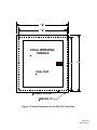
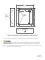
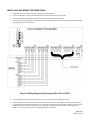
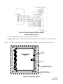
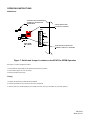
SP4-LOC SAFEPATH REMOTE MICROPHONE AND LOCAL OPERATING CONSOLE INSTALLATION AND OPERATION MANUAL LOCAL OPERATING CONSOLE Part Number: P85173 Rev. B Copyright 2012 Cooper Wheelock Inc., dba Cooper Notification. All rights reserved. INTRODUCTION Thank you for using our products. Use this product according to this instruction manual. Please keep this instruction manual for future reference. The SP4–LOC Remote Microphone and Local Operating Console is designed to be used with the Facility Communications System using the SafePath SP40S panel. It contains the SafePath SPRM Remote Microphone Module and eight, black Push On/Push Off buttons which provide a contact closure to activate the SP40S digital messages in the Push On position. These buttons have an LED that illuminates when in the ON position. A message name plate holder is located above the pushbuttons. An optional red mushroom type, cutoff pushbutton is available for HVAC emergency shutoff. The Remote Microphone (SPRM) incorporates a Push-To-Talk (PTT) microphone and system status LED indicators. The SPRM provides a microphone override for any tone generation, digital voice module prerecorded message, background music, or telephone paging. It is equipped with a keyed lock that, when activated, allows the use of the module. The key cannot be removed in the ON position. The SPRM is fully supervised from the SP40S panel and contains front panel LEDs for remote indications of System Normal, System Trouble and Alarm conditions. Voice frequency response must be 275 Hz to -6.5 kHz +/- 2.4 dB. Power requirements must be 24VDC and are supplied by the SP40S. Input current for standby mode must be 26mA and 35mA in the alarm mode (20mA Max – All Buttons ON). Shielded 6-wire cable must be used. Approvals for the system must include; UL Standard 864, UL Standard 1711, FCC Part 15, and CSFM. The panel must be OSHA 1910.165 and ADA compliant. The SP4-LOC is available in two models: flush-mount and surface-mount. The flush-mount model has a 1/2-inch skirt around the door section, while the surface-mount model door section is flush with the backbox. Both models use the same white 3-1/2-inch deep backbox with three 1/2inch and 3/4-inch double knockouts, one each in the back center, and top and bottom of the backbox. The flush-mount door section has exterior dimensions of 15-1/2 inches wide and 16-1/4 inches high. The surface mount model has dimensions of 14-1/2 inches wide, 15-1/2 inches high and 3-1/2 inches deep. Both models have a pull slam latch to open the continuous hinged door. Both models are available in white. The SP4-LOC can be installed up to 2,000 feet (609.6 meters) from the SP40S panel using 14-18 AWG shielded wiring. NOTATION CONVENTIONS This manual uses the following notation conventions: INDICATES A POTENTIALLY HAZARDOUS SITUATION THAT, IF NOT AVOIDED, COULD RESULT IN SERIOUS PERSONAL INJURY OR DEATH TO YOU AND OR OTHERS. Indicates a potentially hazardous situation that, if not avoided, could result in minor or moderate injury. It may also be used to alert against unsafe practices. SAFETY DE-ENERGIZE ALL ELECTRICAL CIRCUITS AND EQUIPMENT ASSOCIATED WITH INSTALLING THE SP4-LOC. IF THE HVAC PUSHBUTTON OPTION IS BEING ADDED, THE CIRCUIT CAN CONTAIN HIGH VOLTAGE THAT CAN CAUSE SERIOUS INJURY OR DEATH TO THE INSTALLER. Additional copies of this manual may be obtained from www.coopernotification.com in the Technical Support section, or from: Cooper Notification 273 Branchport Ave. Long Branch, N.J. 07740 Tel: (800) 631-2148 Fax: (732) 222- 2588 E-mail: [email protected] P85173 B Sheet 2 of 10 TECHNICAL SPECIFICATIONS Mechanical Dimensions (H x W x D) See Figure 1. Backbox: 15-1/4 x 14-1/2 x 3.5 in. Surface Front: 15-1/4 x 14-1/2 x 1/8 in. Flush Front: 16-1/4 x 15-1/2 x 1/8 in. Weight 8 lbs. Finish White Mounting Indoor Surface Mount Indoor Flush Mount Wiring Entry Top, bottom and back knockouts (1/2-inch and 3/4-inch) (3 total) Door Lock Pull slam latch with 1/8-inch security tamper indicator installation holes. PC Boards SPRM and Pushbutton Environmental Operating Temperature 0 to 49 °C (32 to 120 °F) Storage Temperature -20 to 70 °C (-4 to 158 °F) Humidity, Non-condensing 85±5% at 30±2 °C (86 4 °F) Electrical Pushbutton Switch Rating 20 mA at 24VDC HVAC Mushroom Pushbutton 230VAC at 3 Amps SPRM from the SP40S Maximum distance from SP40S is 2,000 feet using 14–18 AWG shielded wire. 14-18 American Wire Gauge (AWG) 6 Conductor cable with overall Shield. The shield must be connected only at the SP40S Panel. Input Voltage 24VDC at 20mA Max (connected to the Pushbutton Board). 1VRMS audio output to SP40S Contact closure to SP40S P85173 B Sheet 3 of 10 15.50" 14.50" LOCAL OPERATING CONSOLE 15.25" 16.25" PANEL DOOR BACKBOX OUTLINE TRIM RING 1/2" Figure 1: Outside Dimensions for the SP4-LOC Front Door P85173 B Sheet 4 of 10 MOUNTING Comply with all of the latest applicable codes, regulations, laws, standards, and guidelines. 1. Remove the FRONT DOOR ASSEMBLY from the backbox by removing the eight (8) nuts holding the assembly in place (flush-mount only). 2. Remove the INNER PANEL ASSEMBLY (Figure 2) from the backbox. Figure 2: Inner Panel Assembly 3. Mount the backbox assembly. See Figure 3 for mounting holes. Ensure the assembly is properly orientated. NOTE: All mounting holes are laser cut as knockouts. Punch out the holes required for either flush or surface mounting. P85173 B Sheet 5 of 10 14.50" 9.25" FLUSH MOUNT HOLES (8) 1/4"x1/2" SURFACE MOUNT HOLES (4) 11.00" 15.25" DOUBLE KNOCKOUT (3) TOP, BOTTOM, AND BACK 1/2"/3/4" Figure 3: Mounting Holes for Mounting the Backbox, Flush and Surface 4. Connect the conduit fittings to the desired cable knockouts and run the appropriate pushbutton and SPRM wiring into the backbox. If the optional HVAC pushbutton is installed, run the HVAC wiring through a separate conduit away from the pushbutton and remote microphone wiring. Do not use the rear panel knockout. This prevents electrical interference and false troubles from appearing on the SP40S. NOTE: If the SP4-LOC is being flush-mounted and finish work on the location has to be completed, stop here and complete the work before connecting and mounting the inner panel and outer door. P85173 B Sheet 6 of 10 INSTALLING AND WIRING THE INNER PANEL 1. If applicable, mount and wire the optional HVAC Emergency Shutoff Pushbutton. 2. Connect the pushbutton IN wiring to the terminal blocks (TB2 and TB3) as shown in Figure 4 (SP40S). 3. Connect the pushbutton RET (TB4 and TB5) wiring to the next LOC’s IN pushbutton terminal blocks. 4. Connect 28V wiring to the terminal blocks as shown in Figure 4 (SP40S). 28V wiring is needed on the Pushbutton Board to illuminate indicator LEDs when a button is pressed. Figure 4: Wiring Diagram (Pushbuttons) SP4-LOC to SP40S 5. Connect the SPRM to the SP40S. Figure 5 shows the proper wiring connections for the SPRM to the SP40S. 6. To activate supervision at the SP40S, switch the corresponding DIP switch (SP40S – SW7 positions 1 through 8) to the ON position. 7. To eliminate the need for external 10K EOLRs, the user can activate on board EOLRs by the DIP switch (positions 1 through 8) on the Pushbutton Board of the SP4-LOC (shown in Figure 4). Turn the switch ON if the 10K EOLR is needed. If the 10K EOLR is not needed or if it is not the end-of-line, turn the corresponding DIP switch position OFF. P85173 B Sheet 7 of 10 Figure 5: Wiring Diagram SPRM to SP40S Wiring is power limited. 8. Mount the INNER PANEL to the backbox using the four #8-32 truss head screws. 9. Mount the FRONT DOOR to the backbox using the eight washers and #8-32 nuts in the locations shown in Figure 8 (flush-mount only). NOTE: Figure 6 shows a diagram of a surface mount FRONT DOOR with a dotted line indicating the trim ring for a flush-mount door. LOCAL OPERATING CONSOLE 1/8" SECURITY WIRE HOLES SLAM LATCH 1/2" TRIM RING ON FLUSH MOUNT MODEL FRONT RING #8-32 X 3/4" STUDS (8) ON BACK OF FRONT RING Figure 6: Front Door Layout P85173 B Sheet 8 of 10 OPERATING INSTRUCTIONS SP40S Panel AUXILIARY INPUT SUPERVISION JUMPER JP4. REMOVE FOR SUPERVISION. AUX SUP CC/NAC SWITCH SW6 PLACE IN CC POSITION TB6 JP4 _ + CC/NAC SP40S _ +CC/NAC +24V OUT _ 1V 100V 70V 25V J4 AUX IN AUX SW6 AUXILIARY INPUT SELECTION JUMPER J4. SELECT 1V POSITION Figure 7: Switch and Jumper Locations on the SP40S for SPRM Operation See Figure 7 for switch and jumper locations. 1. Set the NAC/CC Switch (SW6) on the SP40S PC Board to the CC position. 2. Set the AUX IN jumper J4 to the 1V position. 3. Remove AUX SUP jumper (JP4) Testing 1. Energize the SP40S Panel. Install the backup batteries. 2. Test each pushbutton circuit to insure the SP4-LOC is operational. 3. Insert key and turn to the ON position for the controls to function. (The key is removable only in the OFF position.) P85173 B Sheet 9 of 10 Figure 8: Exploded View of the SP4-LOC 9/12 P85173 B Sheet 10 of 10 FRONT DOOR ASSEMBLY (SURFACE AND FLUSH) LOCAL OPERATING CONSOLE 3 6 INNER PANEL LOCAL OPERATING CONSOLE HVAC SHUTOFF 5 PARTS LEGEND: 4 2 SP4-LOC BACKBOX 6 1/8" HOLES (2) FOR SECURITY TAMPER INDICATOR 5 OPTIONAL "HVAC SHUTOFF" LABEL AND MUSHROOM HEAD PUSHBUTTON SWITCH SEMS NUT (8) PROVIDED. 4 STUDS FROM FRONT DOOR PANEL #8-32 1/4" DIAMETER HOLE (8) TO ACCEPT #8-32 #8-32 TRUSS HEAD (4) INNER PANEL 3 MOUNTING SCREW 2 ELECTRICAL CONDUIT AND FIELD WIRES. 1 (1/2" AND 3/4" KNOCKOUTS PROVIDED ON TOP, BOTTOM AND BACK FACE.) BACKBOX 1