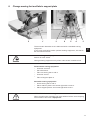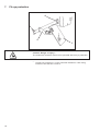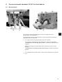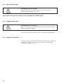
1
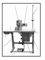
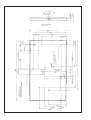
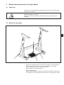
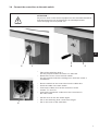
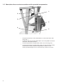
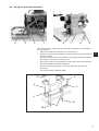
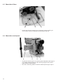
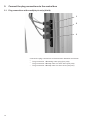
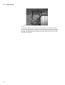
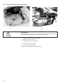
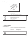
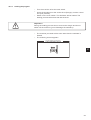
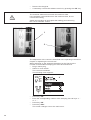
510 CNC automat for bartacking seams and short seams Operating Instructions 1 Installation Instructions 2 Service Instructions 3 Postfach 17 03 51, D-33703 Bielefeld Potsdamer Straße 190, D-33719 Bielefeld Telefon +49 (0) 5 21/ 59 25-00 Telefax +49 (0) 5 21/ 9 25 24 35 www.duerkopp-adler.com Ausgabe / Edition: 02/2006 Printed in Federal Republic of Germany Teile-Nr.:/Part-No.: 0791 510001 Summary Operating Instructions Installation Instructions Service Instructions Interconnection-diagram 9890 510001 B Foreword This instruction manual is intended to help the user to become familiar with the machine and take advantage of its application possibilities in accordance with the recommendations. The instruction manual contains important information on how to operate the machine securely, properly and economically. Observation of the instructions eliminates danger, reduces costs for repair and down-times, and increases the reliability and life of the machine. The instruction manual is intended to complement existing national accident prevention and environment protection regulations. The instruction manual must always be available at the machine/sewing unit. The instruction manual must be read and applied by any person that is authorized to work on the machine/sewing unit. This means: – – – Operation, including equipping, troubleshooting during the work cycle, removing of fabric waste, Service (maintenance, inspection, repair and/or Transport. The user also has to assure that only authorized personnel work on the machine. The user is obliged to check the machine at least once per shift for apparent damages and to immediatly report any changes (including the performance in service), which impair the safety. The user company must ensure that the machine is only operated in perfect working order. Never remove or disable any safety devices. If safety devices need to be removed for equipping, repairing or maintaining, the safety devices must be remounted directly after completion of the maintenance and repair work. Unauthorized modification of the machine rules out liability of the manufacturer for damage resulting from this. Observe all safety and danger recommendations on the machine/unit! The yellow-and-black striped surfaces designate permanend danger areas, eg danger of squashing, cutting, shearing or collision. Besides the recommendations in this instruction manual also observe the general safety and accident prevention regulations! General safety instructions The non-observance of the following safety instructions can cause bodily injuries or damages to the machine. 1. The machine must only be commissioned in full knowledge of the instruction book and operated by persons with appropriate training. 2. Before putting into service also read the safety rules and instructions of the motor supplier. 3. The machine must be used only for the purpose intended. Use of the machine without the safety devices is not permitted. Observe all the relevant safety regulations. 4. When gauge parts are exchanged (e.g. needle, presser foot, needle plate, feed dog and bobbin) when threading, when the workplace is left, and during service work, the machine must be disconnected from the mains by switching off the master switch or disconnecting the mains plug. 5. Daily servicing work must be carried out only by appropriately trained persons. 6. Repairs, conversion and special maintenance work must only be carried out by technicians or persons with appropriate training. 7. For service or repair work on pneumatic systems, disconnect the machine from the compressed air supply system (max. 7-10 bar). Before disconnecting, reduce the pressure of the maintenance unit. Exceptions to this are only adjustments and functions checks made by appropriately trained technicians. 8. Work on the electrical equipment must be carried out only by electricians or appropriately trained persons. 9. Work on parts and systems under electric current is not permitted, except as specified in regulations DIN VDE 0105. 10. Conversion or changes to the machine must be authorized by us and made only in adherence to all safety regulations. 11. For repairs, only replacement parts approved by us must be used. 12. Commissioning of the sewing head is prohibited until such time as the entire sewing unit is found to comply with EC directives. It is absolutely necessary to respect the safety instructions marked by these signs. Danger of bodily injuries ! Please note also the general safety instructions. Index Page: Part 2: Installation Instructions cl. 510 (DAC III) 1. Scope of delivery. . . . . . . . . . . . . . . . . . . . . . . . . . . . . . . . . . . . . . . . . . . . . . 3 2. General notes and transport securing devices . . . . . . . . . . . . . . . . . . . . . . . . . . 3 3. 3.1 3.2 3.3 3.4 3.5 3.6 Mount stand and control circuitry cabinet Table tops . . . . . . . . . . . . . . . . . . . . . . . . . . . . Mount the stand parts. . . . . . . . . . . . . . . . . . . . . Complete the table top . . . . . . . . . . . . . . . . . . . . Connect the control box to the main switch . . . . . . . . Mount the reference value transmitter and the potential Adjust working height . . . . . . . . . . . . . . . . . . . . . . . . . . . . . . . . . . . . . . . . . . . . . . . . . . . . . . . . . compensation . . . . . . . . . . . . . . . . . . . . . . . . . . . . . . . . . . . . . . . . . . . . . . . . . . . . . . . . . . . . . . . . . . . . . . . . . . . . . . . . . . . . . . . . . . . . . 5 5 6 7 8 9 4. 4.1 4.2 4.3 4.4 4.5 Assembly of automatic bartacker Mount the oil pan . . . . . . . . . . . Set up the automatic bartacker . . . Mount the oil lines . . . . . . . . . . . Mount the control panel . . . . . . . Mount the covering cap . . . . . . . . . . . . . . . . . . . . . . . . . . . . . . . . . . . . . . . . . . . . . . . . . . . . . . . . . . . . . . . . . . . . . . . . . . . . . . . . . . 10 11 12 12 13 5. 5.1 5.2 5.3 Connect the plug connections to the control box Plug connections at the multiple pin strip (4-fold) . . . . . . . . . . . . . . . . . . . . . . . . . . . Plug connections at the multiple pin strip (15-fold) . . . . . . . . . . . . . . . . . . . . . . . . . . Cable laying . . . . . . . . . . . . . . . . . . . . . . . . . . . . . . . . . . . . . . . . . . . . . . . . . 14 15 16 6. Change sewing feet and fabric support plate . . . . . . . . . . . . . . . . . . . . . . . . . . . . 17 7. Fit eye protection . . . . . . . . . . . . . . . . . . . . . . . . . . . . . . . . . . . . . . . . . . . . . 18 8. 8.1 8.2 8.3 8.4 Convert automatic bartacker 510-213 to General notes . . . . . . . . . . . . . . . . . Adjust clamp height . . . . . . . . . . . . . . Change thread wiper . . . . . . . . . . . . . Change stop position . . . . . . . . . . . . . . . . . 19 20 20 20 9. 9.1 9.2 9.3 Oil lubrication Fill up oil . . . . . . . . . . . . . . . . . . . . . . . . . . . . . . . . . . . . . . . . . . . . . . . . . . . Oil wicks and felt part in the oil pan . . . . . . . . . . . . . . . . . . . . . . . . . . . . . . . . . . . Oil hook path . . . . . . . . . . . . . . . . . . . . . . . . . . . . . . . . . . . . . . . . . . . . . . . . . 21 22 23 10. 10.1 10.2 10.2.1 10.2.2 10.2.3 10.3 Putting into operation Standard delivery . . . . . . Software installationl . . . . General . . . . . . . . . . . . Loading the program . . . . Dongle-Update via internet Sewing test . . . . . . . . . . . . . . . . 23 24 24 24 26 27 11. 11.1 Optional equipment Sewing light . . . . . . . . . . . . . . . . . . . . . . . . . . . . . . . . . . . . . . . . . . . . . . . . . 28 . . . . . . . . . . . . . . . . . . . . . . . . . . . . . . . . . . . . . . . . . . . . . . . . . . . . . . . . . . . . . . . . . . . . . . . . . . . . . . . . . . . . . . . . . . . . . . . . . . . . . . . . . . . . . . . . . . thick fabrics . . . . . . . . . . . . . . . . . . . . . . . . . . . . . . . . . . . . . . . . . . . . . . . . . . . . . . . . . . . . . . . . . . . . . . . . . . . . . . . . . . . . . . . . . . . . . . . . . . . . . . . . . . . . . . . . . . . . . . . . . . . . . . . . . . . . . . . . . . . . . . . . . . . . . . . . . . . . . . . . . . . . . . . . . . . . . . . . . . . . . . . . . . . . . . . . . . . . . . . . . . . . . . . . . . . . . . . . . . . . . . . . . . . . . . . . . . . . . . . . . . . . . . . . . . . . . . . . . . . . . . . . . . . . . . . . . . . . . . . . . . . . . . . . . . . . . . . . . . . . . . . . . . . . . . . . . . . . . . . . . . . . . . . . . . . . . . . . . . . . 2 1 2 3 4 9 8 5 7 6 1. Scope of delivery What items are supplied dependens on your order. Please check before the installation whether all required parts are available. This description refers to an automatic bartacker the individual components of which are completely delivered by Dürkopp Adler AG. – 1 Machine head incl. oil pan Set of parts “Electro” with: – 2 Control panel – 5 Main switch – 6 DAC control Dürkopp-Adler accessories with: – 3 Yarn stand – Protection cover (not shown) 2. – 8 Stand (optional) – 7 Pedal and bars (optional) – 4 Table top (optional) – 9 Drawer (optional) 2 General notes and transport securing devices ATTENTION ! The automatic bartacker must only be installed by trained specialist staff. Transport securing devices If you have bought an assembled automatic bartacker, the following transport securing devices have to be removed: – Securing tapes and wood battens at machine head, table and stand. 3 4 Screwed nut (4 x) from the underside M6 x 20; observe DIN 7965 Punch-marks from the underside (8 x) 3. Mount stand and control circuitry cabinet 3.1 Table tops The cutouts of self-manufactured table tops must have the dimensions indicated in the sketch. Caution: Danger of injury ! The table tops must have the required load-carrying capacity and strength. 3.2 Mount the stand parts 2 3 1 2 – – – – Mount the individual parts of the stand as shown in the illustration. Set the adjusting screw 3 to ensure the stability of the stand. All four feet of the stand must touch the floor. Screw pedal 2 on the stand strut 1. Align pedal laterally. Shift the pedal sideways so that it is positioned centrally to the oil pan. The stand strut is provided with slotted holes for aligning the pedal. 5 3.3 Complete the table top 6 5 4 – – – – – – 3 2 1 Place the table top on a worktop upside down. Screw the main switch 6 on the underside of the table top on the left. Screw cable duct 5 tight behind the main switch 6. Screw cable duct 2 tight to the left of the lead-through 1. Put the access line 4 in the cable duct. Fasten the access line 4 by means of strain relief 3. 7 – – 6 Place the control box 7 on the underside of the table top and position it in such a way that the side with the 4 sockets points to the left (towards the thread reel holder). Screw the control box with four screws on the punch-marked spot at the underside of the table top. 3.4 Connect the control box to the main switch ATTENTION ! Any kind of work on the electric equipment of the automatic bartacker must be carried out only by electricians or trained personnel. The mains plug has to be pulled out! 2 2 1 4 – – – – – – 5 – – – 3 Take off the switching knob 1. For this purpose loosen the screw 2 in the knob. Remove the cover 3 from the main switch. For this purpose unlock the locking bar in drill-hole 4 with a screwdriver. Run the cable from the control box into the cable duct. Insert the cable in the main switch. Connect the cable cores of the control box to the screws ”T1” and “T2”. Connect the protective conductor of the control box in the main switch. Put the cover on the line switch again. Put on the switching knob 1 and screw it tight. Put on the cover of the cable duct. 7 3.5 Mount the reference value transmitter and the potential compensation 1 6 5 2 4 3 – – – – 8 Screw the reference value transmitter 5 on the stand strut with fixing link 1. Hook the ball mugs of the pedal bars 6 in at the pedal and at the reference value transmitter 5. Screw the potential compensation cable 2 on the fixing link 1. Screw the potential compensation cable 2 of the reference value transmitter and the potential compensation cable 4 of the sewing automate tight on the control box by means of screw 3. 3.6 Adjust working height 1 2 2 The working height is adjustable between 750 and 950 mm (measured up to the top edge of the table top). – Loosen screws 1 at both legs of the stand. In order to prevent twisting, pull out or push in the table top equally on both sides. The scales 10 at the exterior surfaces of the legs serve as adjusting aid. – Tighten both screws 1. 9 4. Assembly of automatic bartacker 4.1 Mount the oil pan 3 2 1 – – 10 Lay oil pan 1 on table top 3, align it and screw it tight through the two through bore-fits 2 with two wood screws. Insert thread reel holder 1 in the drill-hole of the table top and screw tight with nuts and washers. Mount and align the thread reel arms and the thread guides. The thread reel arms and thread guides must be positioned exactly one above the other. 4.2 Set up the automatic bartacker 4 3 2 1 8 7 6 5 The small parts for setting up the automatic bartacker are included in the accessories. – Place the automatic bartacker 1 on the oil pan 4. – Fasten the automatic bartacker on the left and on the right with the fixtures 5 and 8. For this purpose screw the fixtures 5 and 8 tight with the screws 9, the sheets 11 and the counternuts 10. – Insert the machine head support 6 in the drill-hole of the table top. – Tilt the automatic bartacker sideways. – Run the connecting cables 2 under the table top through the opening 3. – Tilt the automatic bartacker back. 9 9 5 8 10 10 11 11 2 4.3 Mount the oil lines 10 – 9 8 Fasten the oil lines 8 and 9 in the oil pan by means of fitting 10. The oil filter must be completely surrounded by the felt. 4.4 Mount the control panel 4 – – 12 3 2 1 Screw the control panel 4 on the automatic bartacker with angle 3. Lay rubber washers between the mounting angle of the control panel and the cast housing. Run the connecting cable 2 under the table top through oil pan 1. 4.5 Mount the covering cap 9 8 10 6 – – – Place the covering cap 9 on the retaining spring 10 from above. Lay the cable of the control panel in the gap 1 of the covering cap before. Screw the covering cap on the automatic bartacker with two screws through the drill-holes 6 and 8. 1 13 2 5. Connect the plug connections to the control box 5.1 Plug connections at the multiple pin strip (4-fold) 1 2 3 Connect the plug connections of the automatic bartacker as follows: – Plug connection 1 è sewing motor plug (four-pole) – Plug connection 2 è step motor for the X-drive (five-pole) – Plug connection 3 è step motor for the Y-drive (five-pole) 14 5.2 Plug connections at the multiple pin strip (15-fold) 5 1 2 3 4 6 2 Connect the plug connections of the automatic bartacker, the control panel and the reference value transmitter as follows: – Plug light barrier /sensor to plug connection 1 (REF-signals) Note: The 8-pole plug is encoded. – Plug magnets to plug connection 5 (PWM) Note: The 8-pole plug is encoded. – Plug encoder signal sewing motor to plug connection 2 (encoder sewing motor) – Plug control panel to plug connection 3 (control panel) – Plug operating elements (pedal switch) via adapter 6 to plug connection 4 (I/O 1-8) 15 5.3 Cable laying 2 To make the tilting of the machine head possible, the cables leading from the head through the opening in the table top to either the multiple pin strip (15-fold) at the control box and to the cable duct must be long enough. For this purpose the cables must be laid to form an arc 2 with the help of cable ties. 16 6. Change sewing feet and fabric support plate 2 1 3 6 5 4 3 The automatic bartacker 510 is delivered with a standard sewing equipment. If you have received a further optional sewing equipment, this has to be mounted as follows: 2 Caution: Danger of injury ! Switch off main switch. Change sewing equipment only when main switch is switched off. Disassemble sewing equipment – Unscrew screws 3. – Pull off holder 5. – Take out sewing feet 4 and 6. – Unscrew screw 1. – Take off support plate 2. Assemble sewing equipment – Insert sewing feet 4 and 6. – Place retainer plate 5 and screw tight with screws 3. – Place support plate 2 and screw tight with screw 1. ATTENTION Risk of breakage ! When changing the clamping foot enter without fail the new clamping foot number in the menu “Equipment“. 17 7. Fit eye protection 4 3 2 1 Caution: Danger of injury ! The automatic bartacker must not be operated without eye protection. – 18 Screw eye protection 1 on the automatic bartacker 4 with fixing bracket 2 and the two screws 3. 8. Convert automatic bartacker 510-213 to thick fabrics 8.1 General notes 2 3 1 2 2 Ex works the automatic bartacker 510-213 is equipped for the processing of normal fabrics. In case thicker fabrics are to be sewn on the automate the following alterations have to be made: · The stop position of the automate has to be altered. Ex works the positioning of the automate is done in the position “Thread lever 3 in the top dead centre” (needle bar stands a little deeper). When converting to thicker fabrics the positioning is done in the position “Thread lever 15° before the top dead centre” (needle bar stands higher). · The standard long thread wiper 1 has to be exchanged for a shorter one. 19 8.2 Adjust clamp height ATTENTION Risk of breakage! When converting the automatic bartacker to thicker fabrics adjust the clamp height in any case. See service instructions chapter 6.3 for adjusting the clamp height. 8.3 Change thread wiper ATTENTION Risk of breakage! When converting the automatic bartacker to thicker fabrics change without fail the thread wiper. See service instructions chapter 4.3 for changing the thread wiper. 8.4 Change stop position The stop position is set in the technician mode in the menu “Machine configuration” via the menu item “Stop position” (see operating instructions chapter 8.5.4.1). 20 9. Oil lubrication Caution: Danger of injury ! Oil can cause skin eruption. Avoid a longer contact with the skin. Wash yourself thoroughly after a contact. ATTENTION ! The handling and disposal of mineral oils is subject to legal regulations. Deliver used oil to an authorized collecting station. Conserve your environment. Be careful not to spill any oil. Fill up the oil reservoirs exclusively with lubricating oil DA-10 or an equivalent oil with the following specification: – Viscosity at 40° C: 10 mm 2 /s – Ignition point: 150° C DA-10 can be bought at the sales points of DÜRKOPP-ADLER AG under the following parts numbers: 250-ml-Container: 9047 000011 1-Litre-Container: 9047 000012 2-Litre-Container: 9047 000013 5-Litre-Container: 9047 000014 2 9.1 Fill up oil 3 2 1 Oil reservoir for lubricating the automatic bartacker – Fill up oil through drill-hole 1. Check oil level in both inspection glasses 2 and 3. The oil level must be above the red marking of both inspection glasses. 21 9.2 Oil wicks and felt part in the oil pan 1 2 ATTENTION ! When assembling the machine and after a longer stop the wicks and the felt parts 1 and 2 have to be soaked with some oil. – – – – – Tilt automatic bartacker sidewards. Soak felt 1 with some oil. Tilt back automatic bartacker . Screw off cover of winder. Give a drop of oil on felt 2. Place on cover of winder and screw tight. 22 9.3 Oil hook path 2 1 Oil – – – hook path Open hook cover. Give a drop of oil between driver 2 and path 1. Shut hook cover. 2 ATTENTION ! When assembling the machine and after a longer stop the hook path and the connecting rod have to be oiled. Caution: Danger of injury ! Switch off main switch. Oil automatic bartacker only when switched off. 10. Putting into operation 10.1 Standard delivery The automatic bartackers are delivered with the following clamping feet: Class 510-211 with clamping foot No. 1 Class 510-212 with clamping foot No. 8 Class 510-213 with clamping foot No. 2 ATTENTION Risk of breakage ! If the standard clamping foot is changed, the corresponding clamping foot number has to be entered. 23 10.2 Software installation 10.2.1 General Loading a specific sewing software in the DACIII control unit is possible with the help of the “Programmed Dongle”. The “Programmed Dongle” has a label indicating the class and software version. Such a loading (booting) may be used in order to provide several DACIII control unit with a sewing software (first installation) or to install a newer machine software (update). With the delivery of the machine only the test software (allowing the loading of sewing software) is installed in the control unit. The test software offers no further functions. If the test software gets damaged during the loading process, it is no longer possible to load a software using a dongle. In such a case use a PC with a loader cable. The detailed procedure for this is described at the homepage of Dürkopp Adler AG “www.duerkopp-adler.com” among the section of “Download Area” and “Software”. The version of the software to used depends on the serial number of control unit: Serial numbers 0302-00101 ... 0307-00643: the control unit should be used with an Axx.x-Version Serial numbers 0307-00644 and higher: the control unit should be used with an Bxx.x-Version The serial number (Serien-Nr./serial no.) is written on the specification plate of the DAC III control unit : CAUTION ! Turn off the main switch before connecting the dongle. 24 10.2.3 Loading the program – Turn the machine off at the main switch. – Insert the dongle 2 into the socket X110 (Dongle) 1 of the control unit (see pictures). Switch on the main switch. The Software will be loaded. The loading process takes less than 60 seconds. – Important ! During the loading process do not remove the dongle and do not switch off the machine (you will damage the software)! – – The machine proceeds with a warm start after the software is loaded. The following screen appears. INFORMATION 2 25 – Remove the dongle 2. – If necessary confirm the software version by pressing the “OK” key. CAUTION ! The machine software must match the machine class. If the software version differs from the machine class, do not confirm the loading. Switch the machine off and repeat the loading proccess using the correct software version. 1 2 The adjustment of the control is described in the operating instructions chapter 8 “Operating the control 510". When switching on the automatic bartacker for the first time the number of the installed clamping foot must be entered first. – Plug in mains plug. – Switch on main switch. The control is initialized. The following menu appears: Configuration 26 – – Press key “OK”. Enter the corresponding number of the clamping foot via keys “ñ ” or “ò ”. – Press key “OK”. – Press key “ESC” The screen changes over to the main menu. Note The menu cannot be left before the clamping foot number has been entered. Calling the configuration menu is only possible after entering the clamping foot number. For the optional equipment, please check the operating instructions (Chapter: Optional Equipment). – 10.2.3 The machine is now ready for use. Dongle-Update via Internet Dongles can be updated with programs available from the Dürkopp Adler homepage. Please open our homepage “www.duerkopp-adler.com” where you will find the relevant programs in the “Download” - section. Prerequisite is our auxiliary download software “ Dongle Copy ” which is available in the same section together with instructions for easy use. 2 27 10.3 Sewing test After completion of the assembly a sewing test should be made. – Plug in mains plug. – Wind up bobbin thread (see operating instructions chapter 7.5) Caution: Danger of injury! Switch off main switch. Thread in needle and bobbin thread only when the automatic bartacker is switched off. – – – – – – – 28 Thread in needle thread (see operating instructions chapter 7.1). Insert hook thread bobbin (see operating instructions chapter 7.6). Switch on main switch. The control is initialized. Choose workpiece to be processed. Make sewing test at low speed first and then at a continuously increasing speed. Check whether the bartack pattern corresponds to the required demands. If the requirements are not met, change thread tensions (see operating instructions chapters 7.2 and 7.7). Possibly the adjustments indicated in the service instructions have to be checked, too, and corrected, if necessary. Check the oil level at both inspection glasses during the operation of the automatic bartacker. 11. Optional equipment 11.1 Sewing light 3 2 1 4 Sewing light 1 (Order No. 9822 510026) and table clamp 3 (Order No. 9822 510027) are available for the automatic bartacker 510. – Clamp sewing light to table top 2. 2 5 – – – – Mount the socket adapter kit 5 (Order No. 9870 001021). Connect the wires to the terminal L1 and L2 of the power switch (see also cahpter 3.4) Connect the safety earth connection to the power switch. Insert the plug to the socket 4 under the table top. 29