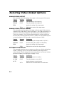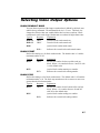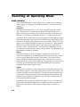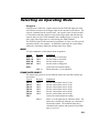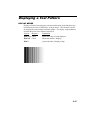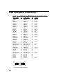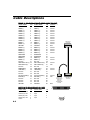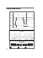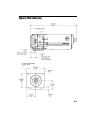
1
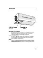
Users Manual Model ES 310 MOTION ANALYSIS SYSTEMS DIVISION EASTMAN KODAK COMPANY EASTMAN KODAK COMPANY Motion Analysis Sytems Division 11633 Sorrento Valley Rd. San Diego California 92121-1097 800-854-7006 KODAK and MEGAPLUS are trademarks. © Copyright Eastman Kodak Company, 1998 91000086-001 Rev. A Printed in U.S.A. Table of Contents CHAPTER 1. INTRODUCTION Introduction ....................................................................................................... 1.1 How to Use This Manual .................................................................................. 1.2 Warranty ........................................................................................................... 1.3 Precautions ........................................................................................................ 1.4 CHAPTER 2. CONTROLS AND CONNECTORS Camera .............................................................................................................. 2.1 Camera Rear Panel ............................................................................................ 2.2 Cables ................................................................................................................ 2.4 Hardware Setup ................................................................................................. 2.5 Routine Maintenance ........................................................................................ 2.6 CHAPTER 3. CAMERA OPERATION Introduction ....................................................................................................... 3.1 Serial Interface Protocol ................................................................................... 3.2 Using RS485 Multi-Drop .................................................................................. 3.4 Selecting Video Output Options ....................................................................... 3.6 Selecting an Operating Mode ............................................................................ 3.8 Setting Exposure Time ...................................................................................... 3.10 Selecting a Trigger Mode .................................................................................. 3.13 Controlling Camera Black Level ...................................................................... 3.14 Setting Camera Gain ......................................................................................... 3.15 Saving Camera Configurations ......................................................................... 3.16 Displaying a Test Pattern .................................................................................. 3.17 Query Commands ............................................................................................. 3.18 CHAPTER 4. INTERFACE SPECIFICATIONS AIA Interface Connector ................................................................................... 4.1 Cable Descriptions ............................................................................................ 4.3 Timing Waveforms ........................................................................................... 4.5 Specifications .................................................................................................... 4.7 Chapter 1. Introduction Introduction How to Use This Manual Warranty Precautions Introduction INTRODUCTION The KODAK MEGAPLUS Camera, Model ES 310 is intended for machine vision, medical imaging, and many other applications. The camera package is compact and is operated through a connection to a host computer. The AIA interface connector, located on the cameras rear panel, sends digital output video to the computer and receives control commands from the computer. Featuring an interline Charge Coupled Device (CCD) sensor array, the camera has 648(H) x 484 (V) light sensitive elements (pixels). These pixels are 9 microns square and have a center to center spacing of 9 microns with a 60 % fill ratio. The camera operates continuously or in a triggered mode. Exposure times as short as 94 microseconds are possible with the cameras electronic shutter and the frame rate is unaffected by the exposure time in continuous mode. The camera has a dual output channel data rate of 20 MHz, with the fastest full frame rate being 85 frames per second. Faster frame rates are possible in some operating modes. The camera can be connected to many commercially available frame grabber boards capable of handling eight bits of digital video data, and requires only eight watts of power. 1.1 How to Use This Manual CHAPTER 1. INTRODUCTION Chapter one describes this Users Manual, a warranty statement and some general precautions to observe when operating this product. CHAPTER 2. CONTROLS AND CONNECTORS Chapter two explains the function of the controls and connectors of the MEGAPLUS Camera. CHAPTER 3. SETUP AND OPERATION Chapter three contains the commands used to operate the camera. The camera is remotely operated by entering commands into a computer connected to the camera. CHAPTER 4. INTERFACE SPECIFICATIONS Chapter four details the signals carried by the AIA interface connector including timing waveforms. 1.2 Warranty New Equipment Warranty KODAK MEGAPLUS Camera EASTMAN KODAK COMPANY, MOTION ANALYSIS SYSTEMS DIVISION, WARRANTS THIS KODAK MEGAPLUS CAMERA AND ACCESSORIES MANUFACTURED BY EASTMAN KODAK COMPANY, TO FUNCTION PROPERLY FOR ONE YEAR FROM THE DATE OF SHIPMENT. Kodak agrees to perform the following equipment warranty services in the United States. 1. Repair service: If shipped to us, repairs will be made at no charge. 2. Parts replacement: Replacement parts installed under warranty will be provided at no charge. THIS WARRANTY DOES NOT APPLY UNDER THE FOLLOWING CONDITIONS: Failure to operate the KODAK MEGAPLUS Camera in accordance with Kodaks written instructions, including environmental specifications listed in the Users Manual. If there is evidence of the KODAK MEGAPLUS Camera being subjected to accidental damage, misuse or abuse. If the KODAK MEGAPLUS Camera has been repaired or tampered with by persons other than Kodak personnel, customer personnel trained by Kodak or without permission of Kodak. Shipping damage is not covered by this warranty. The purchaser has the responsibility to place a claim of damage in shipment with the carrier. KODAK MAKES NO OTHER WARRANTIES, EXPRESSED, IMPLIED, OR OF MERCHANTABILITY FOR THIS EQUIPMENT. IF THIS KODAK MEGAPLUS CAMERA DOES NOT FUNCTION PROPERLY DURING THE WARRANTY PERIOD, KODAK WILL REPAIR IT WITHOUT CHARGE ACCORDING TO THE TERMS STATED ABOVE. REPAIR WITHOUT CHARGE IS KODAKS ONLY OBLIGATION UNDER THIS WARRANTY. KODAK WILL NOT BE RESPONSIBLE FOR ANY CONSEQUENTIAL OR INCIDENTAL DAMAGES RESULTING FROM THE SALE, USE OR IMPROPER FUNCTIONING OF THIS EQUIPMENT EVEN IF LOSS OR DAMAGE IS CAUSED BY THE NEGLIGENCE OR OTHER FAULT OF KODAK. KODAK and MEGAPLUS are trademarks. © Copyright Eastman Kodak Company, 1998 1.3 Precautions FEDERAL COMMUNICATIONS COMMISSION STATEMENTS WARNING: This equipment generates, uses and can radiate radio frequency energy, and if not installed and used in accordance with the instruction manual, may cause interference to radio communications. It has been tested and found to comply with the limits for a Class A computing device pursuant to Subpart B of Part 15 of the FCC Rules and VDE 0871 Class B, which are designed to provide reasonable protection against such interference when operated in a commercial environment. Operation of this equipment in a residential area is likely to cause interference in which case the user at his own expense will be required to take whatever measures may be required to correct the interference. This device complies with Part 15 of the FCC Rules and VDE 0871. Operation is subject to the following two conditions: (1) this device may not cause harmful interference, and (2) this device must accept any interference received including interference that may cause undesired operation. CAUTION A laser beam focused on the sensor, either directly or by specular reflection, can cause permanent damage to the sensor. Any laser powerful enough to produce localized heating at the surface of the sensor will cause damage, even if the camera power is off. A sensor damaged by laser light is not covered by the warranty. OPERATING TEMPERATURE The KODAK MEGAPLUS Camera is designed to operate satisfactorily in an environment where the ambient temperature is between 0 and 40 degrees Centigrade (32 and 104 degrees Fahrenheit), and there is no water condensation present. STORAGE TEMPERATURE Do not store the equipment in an area where the temperature will drop below -25 degrees or exceed 80 degrees Centigrade (-13 to 176 degrees Fahrenheit). Do not allow moisture to condense on the system. SHIPPING When shipping, use the shipping carton in which the unit was originally delivered. Do not ship the equipment in a cargo area where the temperature will drop below -25 degrees or exceed 80 degrees Centigrade (-13 to 176 degrees Fahrenheit). Do not allow moisture to condense on the system. 1.4 Chapter 2. Controls and Connectors Camera Camera Rear Panel Cables Hardware Setup Routine Maintenance Camera MOUNTING THE CAMERA The KODAK MEGAPLUS Camera has a 1/4-20 threaded screw hole for mounting on the bottom of the camera body. There is a second hole, 0.228 inches in diameter, to accommodate a locating pin. ATTACHING THE LENS The KODAK MEGAPLUS Camera uses a C-mount lens. To mount the lens, screw the lens clockwise into the adapter until you are no longer able to turn the lens with light pressure. NOTE A lens cap is installed and shipped with each camera to keep dust from getting on the optical sensor or components. Remove the lens cap and install your lens in a dust free environment. 2.1 Camera Rear Panel The mating connector for the DC power input is manufactured by LEMO as part number FGG.0B.302.CLAD42 Power AIA Video STROBE TRIGGER TRIGGER A coaxial SMA type connector that accepts CMOS TTL signal inputs with a threshold of approximately 2.5 volts. The trigger pulse should have a duration of at least 100 nanoseconds and be transmitted to the camera using a coaxial cable terminated at the camera. The camera synchronizes to an external event using this input. The operator can set the polarity of the trigger signal that the camera will respond to. Timing waveforms are shown on page 4.5, and 4.6 of this manual. STROBE A coaxial SMA type connector that outputs a TTL compatible signal. The strobe output pulse should be transmitted through a 50 ohm coaxial cable with a 50 ohm terminating resistor at the receiving end. The leading edge of this output signal can be used to fire a strobe light. The output signal polarity is user definable. See timing Waveforms in chapter four of this manual. 2.2 Camera Rear Panel DC POWER INPUT This two pin connector is the power input for the camera. The power supply voltage should be between 12 and 28 volts DC measured at the connector on the camera rear panel. The current draw is a maximum of 0.8 amps at the lowest input supply voltage and 0.3 amps at the highest input supply voltage. WARNING Reversing the polarity of the DC voltage input or voltage levels in excess of 30 volts may permanently damage the camera. AIA INTERFACE This is a 68 pin, high density, dual row, D type connector that connects the camera to a frame grabber board and a serial communication interface for camera control. The frame grabber board processes and displays digital 0video from the camera. A complete technical description of the connector and the signals that it carries is contained in chapter four of this manual. VIDEO OUTPUT A BNC type connector provides a 1 volt peak to peak video signal output. This output is intended to drive a coaxial cable terminated in 75 ohm to ground at the receiving end. The video output can be user configured for CCIR or RS170 video standards. See the VFR command on page 3.6 of this manual. 2.3 Cables There are three different cables available to connect the MEGAPLUS Camera to your computer. 68 Pin Male Connector 68 Pin Connector Mates with camera 68 Pin Connector Mates with camera RS232 Cable RS485 Cable Female 9 Pin D-subminiature mates with RS485 Control Line Cable 68 Pin Male Connector 56 0XOWL'URS &DEOH 2.4 Male 68 Pin Connector mates with RS422 Frame Grabber 56 &DEOH Male 68 Pin Connector mates with Frame Grabber 56 &DEOH Female 9 Pin D-subminiature mates with Computer COM port Hardware Setup CONNECT THE CABLES Install the cables as illustrated in component hookup diagram. COMPONENT HOOKUP DIAGRAM 2.5 Routine Maintenance There are no user serviceable parts in the camera. The camera must be returned to the factory for repair if a malfunction occurs. The lens and the sensor cover glass should be cleaned using dust free compressed air. Clean the exterior of the camera with a soft dry cloth. You may dampen a soft cloth with a mild soap solution for stubborn dirt. 2.6 Chapter 3. Camera Operation Introduction Serial Interface Protocol Using RS485 Multi-Drop Selecting Video Output Options Selecting an Operating Mode Setting Exposure Time Selecting a Trigger Mode Controlling Camera Black Level Setting Camera Gain Saving Camera Configurations Displaying a Test Pattern Query Commands Introduction The KODAK MEGAPLUS Camera, Model ES 310, does not have any manual controls. Camera operation is accomplished by commands sent to the camera through a serial data link from a personal computer. In this chapter we will present the various operating modes of the camera with an explanation of the function followed by the command sequence that must be transmitted by the computer. The camera serial data link is configurable as RS232 or RS422/ RS485. The command syntax is the same in either case. A list of the camera functions, their commands, and the page where an explanation of each function can be found follows: Function Command Page Set Communications Port ..............................SCP ........................................... 3.3 RS485 Multi-Drop Address Set ....................ADR ......................................... 3.4 RS485 Multi-Drop Select ..............................MDD ........................................ 3.5 RS485 Multi-Drop, Log Camera ..................LOG ......................................... 3.5 Analog Video Output ....................................VID ........................................... 3.6 Analog Video Output Format ....................... VFR .......................................... 3.6 Alternate Row Select ....................................ALT .......................................... 3.6 Block Readout Mode ....................................BLK .......................................... 3.7 Block Start ..................................................... BST .......................................... 3.7 Block End ......................................................BSP ........................................... 3.7 Mode .............................................................MDE ......................................... 3.9 Frame Rate Select ......................................... FRS ........................................... 3.9 Exposure ........................................................EXE .......................................... 3.10 Auto Expose Select ....................................... AEX ......................................... 3.10 Auto Expose Video Level ............................. SET ........................................... 3.10 Auto Expose Vertical Address ...................... AXX ......................................... 3.11 Auto Expose Horizontal Address ..................AXY ......................................... 3.12 Trigger ........................................................... TRS, TRM, TRE ...................... 3.13 Black Level ................................................... BKE .......................................... 3.14 Black Level Balance .....................................BKB ......................................... 3.14 Digital Gain ................................................... DGN ......................................... 3.15 Gain Balance .................................................GAB ......................................... 3.15 Strobe Polarity ............................................... STP ........................................... 3.15 Restore Factory Settings ...............................RFS ........................................... 3.16 Save ............................................................... SAV .......................................... 3.16 Reset ..............................................................RST .......................................... 3.16 Display Wedge .............................................. WDG ........................................ 3.17 Status Query ..................................................STS ........................................... 3.18 Identification Query ......................................IDN ........................................... 3.18 3.1 Serial Interface Protocol SERIAL COMMUNICATIONS PROTOCOL The camera uses a full duplex UART type asynchronous system, using standard nonreturn-to-zero (NRZ) format (one start bit, eight data bits, one stop bit, no parity). The baud rate is fixed at 9600. The character code is based on the ASCII standard. The character flow control protocol is XON/XOFF. XON is assigned DC1 (control-Q) and XOFF is assigned DC3 (control-S). The receiver sends the XOFF character when it wants the sender to pause in sending data and an XON character when it wants the sender to resume. The camera will recognize a command as three command characters, followed by a space character, followed by an argument that consists of one or more characters, ended by the carriage return and line feed characters. The camera responds to a valid command with a carriage return and line feed (CR-LF) The camera will recognize a query as three command characters followed by the question mark character, then ended by the carriage return character. The camera responds to a query with three command characters, followed by a space bar character, followed by an argument that consists of one or more characters, then ended by carriage return and line feed (CR-LF). ERROR MESSAGES The camera can respond to an erroneous command or query in one of four possible ways. Message from camera Explanation ERROR-SYNTAX The camera cannot make sense of the command. ERROR-ARG RANGE The command is recognized but the argument is out of range or indecipherable. ERROR-TRANSMISSION The receiver detected a transmission error such as buffer overflow, parity, or framing. ERROR-MULTIDROP CONFIGURATION NOTE 3.2 The command was recognized but conflicts with current multidrop settings In the following text the command and argument that are sent to the camera are in bold type. The carriage return and line feed at the end of each command are not shown as they are required in every instance. Serial Interface Protocol SETTING SERIAL COMMUNICATIONS MODE The camera can use either an RS232 or an RS422/RS485 connection for serial communication, but your host computer must have both RS232 and RS422/ RS485 communications capability to use this command. NOTE Type In: Response Explanation SCP 232 CR-LF Sets the camera serial port to respond to RS232 signals. SCP 422 SCP? CR-LF Sets the camera serial port to respond to RS422 signals. Queries the COM port setting. SCP x Means the COM mode is set to x. RS422 and RS485 signal levels and connections are the same. Only two devices can communicate using RS422 electronic driver circuits. Multiple devices can be connected together using RS485 electronic driver circuits, as illustrated by Multi-Drop on the next pages. Procedure Assuming you are using an RS232 connection, type in SCP 422. With power still applied to the camera, disconnect the RS232 cable and substitute an RS422/RS485 connection. Type in SAV to lock in the RS422 option. The camera ignores the SCP command if power is turned off before the SAV command is entered. 3.3 Using RS485 Multi-Drop RS485 MULTI-DROP, ADDRESS SET This command is invalid when multi-drop mode is on (see below). Assign an address to a camera with this command and then execute a SAV command (page 3.15). The cameras address will default to zero when its power is turned off if you do not issue a save command after changing a cameras address. The address is used to send a camera commands when in RS485 multi-drop mode. Type In: ADR x Response CR-LF Explanation Where x must be a unique address for each camera connected to your RS485 network. An address must be an integer between 0 and 99. Cameras are shipped from the factory with their address set to 0. ADR? Queries a camera for its address setting. ADR x Means the camera address is set to x. RS485 MULTI-DROP SELECT Use this command to turn the multi-drop mode on or off. This command should be used when you are connected to only one camera, at the same time you assign a camera its address, for example. This command is not valid if you are using an RS232 communications link. When multi-drop mode is on, all cameras connected to the RS485 communications link listen for commands, however only the camera addressed by the last LOG command will respond to commands. Type In: Response Explanation MDD OF CR-LF Turns multi-drop mode off. MDD ON CR-LF Turns multi-drop mode on. MDD? Queries the multi-drop mode setting. MDD x Multi-Drop is set to x LOG CAMERA RS485 MULTI-DROP The log command instructs a specific camera to respond to subsequent commands. The camera addressed with the LOG command is the only camera that will respond to serial commands until you use the LOG command to address another camera. This command is invalid when multi-drop mode is off. Type In: Response Explanation LOG x CR-LF Where x is the address of the camera that you want to respond to all subsequent commands. The address range is from 0 to 99. Use the ADR? command to get the address of the currently logged camera. 3.4 Using RS485 Multi-Drop Procedure 1. Switch each camera to RS422 operation using the procedure detailed on page 3.3 of this manual. 2. Give each camera a unique address using the ADR and SAV commands. Assign the camera that will be furthest away from the host computer an address of 99. When you are using multi-drop communications the camera furthest away from the host computer must have resistive terminators connected to the RS485 signal lines. Setting the last cameras address to 99 connects internal termination resistors to the RS485 lines of that camera. 3. Use the MDD ON command to turn multi-drop mode on prior to connecting a camera to a network like the one illustrated at the bottom of this page. Each computer has a frame grabber board to process the images from the camera connected to it. Personal computer number one is controlling all of the cameras through its RS485 I/O card. 3.5 Selecting Video Output Options ANALOG VIDEO OUTPUT This command controls the analog video output on the rear panel of the camera. Type In: Response Explanation VID ON CR-LF Turns the analog video output on. VID OF CR-LF Turns the analog video output off. VID? Queries the analog video output status. VID x Indicates the current video output status. ANALOG VIDEO OUTPUT FORMAT This command causes the analog video output on the rear panel of the camera to conform to the CCIR or RS170 video specification. The CCIR specification is in general use outside the United States with the RS170 specification being the U. S. television standard. The CCIR specification defines a vertical resolution of 625 lines and a vertical refresh rate of 50 Hz. The RS170 video standard requires a vertical resolution of 525 lines and a vertical refresh rate of 60 Hz. Type In: Response Explanation VFR NTS CR-LF Sets the analog video output to RS170 (NTSC). VFR PAL CR-LF Sets the analog video output to CCIR (PAL). VID? Queries the analog video output status. VFR x Indicates the current video output format. ALTERNATE ROW SELECT This command causes the sensor to output every other row of pixels during frame readout. With only 242 rows of valid video data the picture height will be reduced by half. The advantage of this mode of operation is an increase in frame rate from 85 frames per second (fps) to roughly 133 fps. Type In: Response Explanation ALT ON CR-LF Turns the alternate row mode on. ALT OF CR-LF Turns the alternate row mode off. ALT? Queries alternate row mode status. ALT x 3.6 Indicates the current alternate row mode status. Selecting Video Output Options BLOCK READOUT MODE You can choose a portion of the image to readout that is defined by the block start and block stop commands. The minimum block size is 17 rows. The block size changes the effective fame rate, smaller blocks take less time to read out. Block readout mode can be used along with alternate row readout for higher frame rates. Type In: Response Explanation BLK ON CR-LF Turns the block readout mode on. BLK OF CR-LF Turns the block readout mode off. BLK? Queries block readout mode status. BLK x Indicates the current block readout mode status. BLOCK START Defines the starting row for block readout mode. The default value is 1 and the maximum number is 225. Type In: Response Explanation BST x CR-LF Sets the row number for the top of the read out block. Where x is a number between 1 and 225 with 1 as the default value BST? Queries block readout starting row number. BST x Indicates the current block starting number. BLOCK STOP Defines the ending row for block readout mode. The default value is 242 and the minimum number is 18. The block stop number must be seventeen or more rows greater than the block start number. Type In: Response Explanation BSP x CR-LF Sets the row number for the bottom of the read out block. Where x is a number between 18 and 242 with 242 as the default value BSP? Queries block readout ending row number. BSP x Indicates the current block ending number. 3.7 Selecting an Operating Mode MODE CONTROL The KODAK MEGAPLUS Camera operates in one of four modes, continuous, control, trigger, or retriggered. The mode of operation is selected by the mode command. Continuous The camera can take pictures at 15, 25, 30, 50, 60, and 85 frames per second (fps). The frame rate is set by the FRS command, The default frame rate is 30 fps. The exposure time range is from 94 microseconds to one divided by the frame rate. For example, the maximum exposure is 11 milliseconds at 85 fps. The camera can be synchronized to an external trigger source through the Trigger input on the rear panel of the camera or the EXPOSE input of the AIA interface connector. The trigger input frequency must be between 84.5 and 85.5 Hz. If the camera is not externally triggered its frame rate will be 84.5 fps. When multiple cameras are driven from the same trigger source they will be synchronized to each other within ± 100 nanoseconds. The digital video output pauses for one row time at the time the exposure starts for the next frame. See continuous mode timing diagram in chapter 4 for details. Control The start and exposure time of each image is controlled directly by the user. Control is accomplished by the EXPOSE input pins in the AIA interface connector or the trigger input on the rear panel of the camera. The exposure time is equal to the time the EXPOSE input signal is true. The frame rate is inversely proportional to the exposure plus readout time. The exposure time can be as long as needed, but at room temperatures dark field nonuniformities become more noticeable with increasing exposure times. Trigger Each exposure is started by a signal connected to the EXPOSE input pins of the AIA interface connector or the trigger input on the rear panel of the camera. The exposure command sets the exposure time. An exposure starts 20 microseconds (± 100 nanoseconds) after the active edge of the trigger pulse and ends after the exposure time set by the EXE command. The active edge of the trigger pulse is selected using the TRM command. The EXPOSE input sets the start time for each frame of video. The camera will ignore additional EXPOSE signals until it completes the current exposure. The trigger mode of operation is used to capture a single image or sequence of images. 3.8 Selecting an Operating Mode Retriggered Each exposure is started by a signal connected to the EXPOSE input pins of the AIA interface connector or the trigger input on the rear panel of the camera. The exposure command sets the exposure time. An exposure starts 20 microseconds (± 100 nanoseconds) after the active edge of the trigger pulse and ends after the exposure time set by the EXE command, unless another trigger is received. The active edge of the trigger pulse is selected using the TRM command. The EXPOSE input sets the start time for each frame of video, even if the preceding frame readout is not complete. An EXPOSE signal stops the current frame, outputs the video data to that point, and then starts a new frame. MODE Use this command to set the camera mode of operation. Type In: Response Explanation MDE CS MDE CD MDE TR MDE RT CR-LF CR-LF CR-LF CR-LF Sets the mode to continuous. Sets the mode to controlled. Sets the mode to trigger. Sets the mode to retriggered. MDE? Queries the current mode setting. MDE xx Means the mode is set as indicated. FRAME RATE SELECT The camera may operate in several different frame rates specified in frames per second (fps) Type In: Response Explanation FRS 15 FRS 25 FRS 30 FRS 50 FRS 60 FRS 85 CR-LF CR-LF CR-LF CR-LF CR-LF CR-LF Sets the camera frame rate to 15 fps. Sets the camera frame rate to 25 fps. Sets the camera frame rate to 30 fps. Sets the camera frame rate to 50 fps. Sets the camera frame rate to 60 fps. Sets the camera frame rate to 85 fps. FRS? Queries the camera frame rate setting. FRS xx Where xx is the frame rate in continuous mode. The frame rate is modified by alternate row readout and block mode readout. The modified frame rate is calculated in the camera, and reported when a FRS? query is received. 3.9 Setting Exposure Time EXPOSURE This command sets the camera exposure time. Enter an exposure time value between 94 microseconds, and about (1/frame rate), in milliseconds, when you are in continuous mode. The maximum exposure time is 96 milliseconds in trigger and retrigger modes. The camera picks a valid exposure time closest to the value you entered. The exposure time setting is not valid in control mode. The exposure time range is affected by the alternate row and block mode settings. Type In Response Explanation EXE xx.xxx CR-LF Sets the exposure time in milliseconds EXE? Queries the current exposure setting. EXE xx.xxx Where xx.xxx is the exposure time expressed in milliseconds. AUTO EXPOSE SELECT The camera adjusts its exposure time to hold a user set video level as scene illumination changes. The camera takes a digital video sample within an exposure window. The exposure window is a 128 pixels wide by 256 rows high. The user can set the location of the exposure window or accept the default location near the center of the image. The average amplitude of the video in the exposure window is then used to control the exposure time. Type In Response Explanation AEX ON CR-LF Turns auto expose on, holding the video in the exposure window to the value selected by the SET command. AEX OF CR-LF Turns auto expose off. AEX CAL CR-LF The camera checks the video level within the exposure window, and then turns on the auto exposure function to maintain that video level, rather than using the level selected by the SET command. AEX? Queries the auto expose status. AEX x NOTE 3.10 Means that auto expose is set to x. When you are using alternate row and/or block readout modes avoid having black pixels fall inside the exposure window. Black areas inside the exposure window will cause errors in the auto exposure process. Adjust the block start and stop values or the exposure window position so that only valid video data is sampled for the auto exposure function. Setting Exposure Time AUTO EXPOSE VIDEO LEVEL Sets the target video level for the auto expose function. Video level ranges from 0 at black to 127 for white. Type In: Response Explanation SET xxx CR-LF Sets the target video level to xxx with a range between 0 and 127. SET? Queries the camera for the current target video level. SET xxx Means that the target video level is set as indicated. AUTO EXPOSE VERTICAL ADDRESS Sets the vertical location of the top edge of the 256 rows high exposure window. The auto expose function samples every other row so the image heighth becomes 242, and the exposure window becomes 128 high. The default value of 55 places the exposure window near the center of the image, top to bottom. Type In: Response Explanation AXY yyy CR-LF Sets the vertical row address for the upper left corner of the exposure window. The default value is 55 and the range of values is from 1 to 114. AXY? Queries the camera for the current sample box vertical location. AXY yyy Where yyy is the auto expose vertical address. 648 pixels 255 pixels 128 pixels 265 pixels Auto Exposure Window Actual picture height is 484 rows. Auto Exposure uses every other row when positioning the Auto Exposure Window for a row pair count of 242. 55 row pairs 242 row pairs 128 row pairs 59 row pairs 3.11 Setting Exposure Time AUTO EXPOSE HORIZONTAL ADDRESS Sets the horizontal location of the left hand edge of the 128 pixel wide exposure window. The default value of 255 puts the exposure window near the center of the image, left to right. Type In: Response Explanation AXX xxx CR-LF Sets the horizontal pixel address for the upper left corner of the exposure window. The default value is 255 and the range of values is from 1 to 517. AXX? Queries the camera for the current sample box horizontal location. AXX xxx 3.12 Where xxx is the auto expose horizontal address. Selecting a Trigger Mode TRIGGER This command selects the trigger source and polarity. There are two trigger inputs, the SMA connector labeled Trigger, and the EXPOSE input carried by the AIA interface connector, on the rear panel of the camera. Type In: Response Explanation TRS AIA CR-LF Selects the AIA interface connector EXPOSE signal as the trigger source. TRS EXT CR-LF Selects the trigger connector on the rear panel as the trigger source. TRS? Queries the trigger source. TRM P CR-LF A positive going edge at the EXPOSE input of the AIA interface connector will start an exposure. This command automatically enables the EXPOSE input if it was disabled. TRM N CR-LF A negative going edge at the EXPOSE input of the AIA interface connector will start an exposure. This command automatically enables the EXPOSE input if it was disabled. TRM? Queries current EXPOSE polarity. TRM P Means a positive going edge at the EXPOSE input triggers the camera. TRM N Means a negative going edge at the EXPOSE input triggers the camera. TRM O Means EXPOSE input port has been disabled. This can only occur if TRE 0 or TRE 1 has been executed. TRE 0 CR-LF Forces the EXPOSE signal true and disables the EXPOSE input. Use the TRM command to enable the EXPOSE input. Control mode only. TRE 1 CR-LF Forces the EXPOSE signal false and disables the EXPOSE input. Use the TRM command to enable the EXPOSE input. Control mode only. TRE? Queries current state of TRIGGER command. TRE 0 TRE 1 Means an exposure is taking place. Means the camera is in the transfer frame and then idle state. 3.13 Controlling Camera Black Level BLACK LEVEL The black level control functions much like the brightness control on a television set. The fixed video black level is set at the factory so that the output video is just above the black clipping level with the lens capped. The black level can be varied over a range of plus or minus 50 percent of peak white video. Type In: Response Explanation BKF CR-LF Sets the black level to an internal fixed value of approximately 10 counts above zero. BKE xxxx CR-LF The black level range, xxxx, is from -2730 to 1365. BKE? Queries current black level setting. BKF BKE xxxx NOTE Means the black level is at the factory preset level. Means black level externally set to the value indicated. The video will be clipped to 0 counts until it overcomes a negative offset. The video will be offset towards white by a positive offset. BLACK LEVEL BALANCE The black level of the two output video channels are matched at the factory to minimize row to row shading. The black level balance command adjusts the black level of one channel with respect to the other. The adjustment range is from -128 to 127. With the camera in dual channel readout operation and the lens capped observe the video monitor and change the black level balance until you are satisfied with the pictures that you see. Type In: Response Explanation BKB xxxx CR-LF Sets the black level of one channel with respect to the other where xxxx ranges between -128 and 127. BKB? Queries the current black level balance setting. BKB xxxx Means the black level is set to xxxx Sample commands with arguments: 3.14 BKB 0 Sets the camera black level balance to a value of 0. BKB -100 Sets the camera black level balance to a value of -100. BKB 30 Sets the camera black level balance to a value of 30. Setting Camera Gain DIGITAL GAIN Sets the camera gain to a factor of 1, 2 or 4. Type In: Response Explanation DGN 1 CR-LF Sets the camera gain to unity. DGN 2 DGN 4 CR-LF CR-LF Sets the camera gain to times two. Sets the camera gain to times four. DGN? Queries the current gain setting. DGN x Indicates that the gain is set to the factor value given. GAIN BALANCE The gain of the two output video channels are matched at the factory to minimize row to row shading. The gain balance command adjusts the gain of one channel with respect to the other. The adjustment range is from -128 to 127. With the camera in dual channel readout mode observe a uniform white field with a video amplitude of 70 % on the video monitor. Change the gain balance until the best possible image is obtained. Type In: Response Explanation GAB xxxx CR-LF Sets the gain of one channel with respect to the other where xxxx ranges between -128 and 127. GAB? Queries the current gain setting. Sample commands with arguments: GAB 0 GAB -100 GAB 30 Sets the camera gain balance to a value of 0. Sets the camera gain balance to a value of -100. Sets the camera gain balance to a value of 30. STROBE POLARITY The strobe output on the rear panel of the camera provides a trigger pulse for the user. The polarity of the strobe signal is set by this command. The strobe output can drive a 50 ohm load and has a pulse width of 5 microseconds. Type In: Response Explanation STP P CR-LF Makes the strobe output pulse polarity positive. STP N STP? CR-LF Makes the strobe output pulse polarity negative. Queries the strobe output polarity. 3.15 Saving Camera Configurations RESTORE FACTORY SETTINGS Use this command to return the camera black level balance and gain balance settings to their original values as set by the factory. SAVE Type In: Response Explanation RFS CR-LF Restores the factory settings for black level balance and gain balance. Type In: Response Explanation SAV RESET Type In: RST 3.16 CR-LF Saves the current camera settings to the cameras internal memory; these settings will be recalled by performing a reset or turning the camera power on. Response Explanation CR-LF Resets the camera to the settings as last saved. Removing and then restoring power to the camera also performs a reset. Displaying a Test Pattern DISPLAY WEDGE Displays a linearly increasing gray scale that reaches peak white and then resets to black near the center of the picture, as shown below. This function is useful for aligning the camera image to a frame grabber. The display wedge defaults to off when the power to the camera is turned off. Type In: Response Explanation WDG ON CR-LF Means the wedge is being displayed. WDG OF CR-LF Means the camera is imaging. WDG? Queries the state of display wedge. 3.17 Query Commands STATUS QUERY The status query command enables the user to get all the camera operating parameter information with a single command. Type In: Response STS? Response Explanation Gives complete camera status with one query. The following parameters are transmitted with a carriage return after each parameter: Definition Example GAB xxxx .. Shows the gain balance setting. ...................................GAB 36 BKB xxxx .. Shows the black level balance setting. ........................BKB 100 BKE xxxx ... Shows black level setting. ...........................................BKE 58 MDE xx ...... Shows the operating mode. .........................................MDE CS EXE xx ....... Shows the exposure time ............................................. EXE 58 STP x .......... Show the strobe pulse polarity ....................................STP P TRM x ........ Shows the trigger logic polarity. ................................. TRM P TRS xxx ..... Selects the trigger source ............................................. TRS AIA TRE x ......... Shows the exposure state. ............................................TRE 1 DGN x ........ Shows the digital gain setting. .....................................DGN 1 AEX xx ...... Shows the auto exposure setting. ................................AEX ON AXX x ........ Shows the auto exposure horizontal address. ..............AXX 260 AXY x ........ Shows the auto exposure vertical address. ..................AXY 89 BLK xx ....... Shows the block select setting. ....................................BLK ON BST x ......... Shows the block start address. .....................................BST 1 BSP x .......... Shows the block stop address. .....................................BSP 242 ALT x ......... Shows alternate row select setting. ..............................ALT OF MDD x ....... Shows the multi-drop select setting. ............................ MDD OF ADR x ........ Shows the camera multi-drop address. ........................ADR 1 SET xx ........ Shows the auto exposure reference level. ...................SET 64 SCP xxx ...... Sets the communications port protocol .......................SCP 232 IDENTIFICATION QUERY Type In: Response IDN ? KODAK MEGAPLUS Camera Model ES 310,V1.00 Explanation Queries the camera for model number and software version. 3.18 Chapter 4. Interface Specifications AIA Interface Connector Cable Descriptions Timing Waveforms Specifications AIA Interface Connector INTRODUCTION Chapter four gives you the information needed to interface the KODAK MEGAPLUS Camera, Model ES 310 to a frame grabber device. The KODAK MEGAPLUS Camera, Model ES 310 is a black and white camera with dual eight bit digital video outputs. Each frame has 648 columns and 484 rows of pixels (picture elements) containing valid video data. AIA INTERFACE CONNECTOR All the signals referred to in this section are present at the AIA interface connector on the rear panel of the camera. Table 1 lists each signal and its pin number. The connector for this port is a 68 pin, high density, dual row, D type connector. This connector is the same as that used for the SCSI-2 B cable interface. The connector has .050 pin spacing and a D-type shell that is 2.5 inches long. DIGITAL VIDEO OUTPUTS The camera has two digital video output channels, A and B, each with eight bits labeled MSB through MSB-7. The MSB is the Most Significant Bit and MSB-7 is the LSB (Least Significant Bit) in your camera configuration. These signals are output as differential pairs with signal levels conforming to the RS422 specification. The non inverting part of the differential pair is present on the output labeled (+), while the inverting part of the differential pair is present on the output labeled (-). TIMING OUTPUTS There are three timing outputs presented on the AIA interface connector. They are FRME ENA (frame enable), LINE ENA (line enable) and PIX DATA STRB (pixel data strobe). These signals are output as differential pairs with signal levels conforming to the RS422 specification. The non inverting part of the differential pair is present on the (+) output , while the inverting part of the differential pair is present on the (-) output. A signal is true when the (+) line is more positive than the (-) line. CONTROL INPUTS The control input EXPOSE is provided as a means of externally synchronizing the camera. This input is designed to accept RS422 differential, or single ended TTL. To drive this input differentially connect both the (+) and (-) inputs to an RS422 driver. Connect one input to a TTL driver and leave the other input floating to drive the EXPOSE input from a single ended signal source. 4.1 AIA Interface Connector TABLE 1 AIA INTERF ACE CONNECT OR PINOUT ON REAR OF CAMERA INTERFA CONNECTOR SIGNAL NAME GROUND AMSB (+) AMSB-1 (+) AMSB-2 (+) AMSB-3 (+) AMSB-4 (+) AMSB-5 (+) AMSB-6 (+) AMSB-7 (+) BMSB (+) BMSB-1 (+) GROUND BMSB-2 (+) BMSB-3 (+) BMSB-4 (+) BMSB-5 (+) RESERVED RESERVED BMSB-6 (+) BMSB-7 (+) Not used SER CNTRL OUT(+) SER CNTRL IN(+) Not used FRME ENA(+) LINE ENA(+) Not used Not used PIX DATA STRB(+) EXPOSE(+) Not used Not used Not used GROUND PIN 1 2 3 4 5 6 7 8 9 10 11 12 13 14 15 16 17 18 19 20 21 22 23 24 25 26 27 28 29 30 31 32 33 34 SIGNAL NAME GROUND AMSB (-) AMSB-1 (-) AMSB-2 (-) AMSB-3 (-) AMSB-4 (-) AMSB-5 (-) AMSB-6 (-) AMSB-7 (-) BMSB (-) BMSB-1 (-) GROUND BMSB-2 (-) BMSB-3 (-) BMSB-4 (-) BMSB-5 (-) RESERVED RESERVED BMSB-6 (-) BMSB-7 (-) Not used SER CNTRL OUT(-) SER CNTRL IN(-) Not used FRME ENA(-) LINE ENA(-) Not used Not used PIX DATA STRB(-) EXPOSE(-) Not used Not used Not used GROUND 35 68 1 34 As viewed from the rear panel 4.2 PIN 35 36 37 38 39 40 41 42 43 44 45 46 47 48 49 50 51 52 53 54 55 56 57 58 59 60 61 62 63 64 65 66 67 68 SOURCE Both Camera Camera Camera Camera Camera Camera Camera Camera Camera Camera Both Camera Camera Camera Camera Camera Camera Camera User Camera Camera Camera User Both Cable Descriptions TABLE 2 INTERF ACE CABLE PIN OUT INTERFA OUT,, SIGNAL NAME GROUND AMSB (+) AMSB-1 (+) AMSB-2 (+) AMSB-3 (+) AMSB-4 (+) AMSB-5 (+) AMSB-6 (+) AMSB-7 (+) BMSB (+) BMSB-1 (+) GROUND BMSB-2 (+) BMSB-3 (+) BMSB-4 (+) BMSB-5 (+) RESERVED RESERVED BMSB-6 (+) BMSB-7 (+) Not used RESERVED RESERVED Not used FRME ENA(+) LINE ENA(+) Not used Not used PIX DATA STRB(+) EXPOSE(+) Not used Not used Not used GROUND PIN 1 2 3 4 5 6 7 8 9 10 11 12 13 14 15 16 17 18 19 20 21 22 23 24 25 26 27 28 29 30 31 32 33 34 SIGNAL NAME GROUND AMSB (-) AMSB-1 (-) AMSB-2 (-) AMSB-3 (-) AMSB-4 (-) AMSB-5 (-) AMSB-6 (-) AMSB-7 (-) BMSB (-) BMSB-1 (-) GROUND BMSB-2 (-) BMSB-3 (-) BMSB-4 (-) BMSB-5 (-) RESERVED RESERVED BMSB-6 (-) BMSB-7 (-) Not used RESERVED RESERVED Not used FRME ENA(-) LINE ENA(-) Not used Not used PIX DATA STRB(-) EXPOSE(-) Not used Not used Not used GROUND PIN 35 36 37 38 39 40 41 42 43 44 45 46 47 48 49 50 51 52 53 54 55 56 57 58 59 60 61 62 63 64 65 66 67 68 MA TES WITH PC COM POR T MATES PORT SIGNAL NAME Open Transmit, Cam (TX) Receive, User (RX) Open Ground PIN 1 2 3 4 5 SIGNAL NAME Open Connect to pin 8 Connect to pin 7 Open PIN 6 7 8 9 SOURCE Both Camera Camera Camera Camera Camera Camera Camera Camera Camera Camera Both Camera Camera Camera Camera Camera Camera Camera Camera Camera User Both 1 34 35 68 1 5 6 9 4.3 Cable Descriptions TABLE 3. RS422/RS485 MUL TI-DROP CABLE PIN OUT MULTI-DROP OUT,, SIGNAL NAME GROUND AMSB (+) AMSB-1 (+) AMSB-2 (+) AMSB-3 (+) AMSB-4 (+) AMSB-5 (+) AMSB-6 (+) AMSB-7 (+) BMSB (+) BMSB-1 (+) GROUND BMSB-2 (+) BMSB-3 (+) BMSB-4 (+) BMSB-5 (+) RESERVED RESERVED BMSB-6 (+) BMSB-7 (+) Not used SER CNTRL OUT(+) SER CNTRL IN(+) Not used FRME ENA(+) LINE ENA(+) Not used Not used PIX DATA STRB(+) EXPOSE(+) Not used Not used Not used GROUND PIN 1 2 3 4 5 6 7 8 9 10 11 12 13 14 15 16 17 18 19 20 21 22 23 24 25 26 27 28 29 30 31 32 33 34 SIGNAL NAME GROUND AMSB (-) AMSB-1 (-) AMSB-2 (-) AMSB-3 (-) AMSB-4 (-) AMSB-5 (-) AMSB-6 (-) AMSB-7 (-) BMSB (-) BMSB-1 (-) GROUND BMSB-2 (-) BMSB-3 (-) BMSB-4 (-) BMSB-5 (-) RESERVED RESERVED BMSB-6 (-) BMSB-7 (-) Not used SER CNTRL OUT(-) SER CNTRL IN(-) Not used FRME ENA(-) LINE ENA(-) Not used Not used PIX DATA STRB(-) EXPOSE(-) Not used Not used Not used GROUND PIN 35 36 37 38 39 40 41 42 43 44 45 46 47 48 49 50 51 52 53 54 55 56 57 58 59 60 61 62 63 64 65 66 67 68 MA TES WITH RS422/RS485 I/O CARD MATES 4.4 SIGNAL NAME PIN SIGNAL NAME PIN Transmit (TX+) Cam 1 Open 6 Transmit (TX-) Cam 2 Open 7 Receive (RX-) User 3 Open 8 Receive (RX+) User 4 Open 9 Ground 5 SOURCE Both Camera Camera Camera Camera Camera Camera Camera Camera Camera Camera Both Camera Camera Camera Camera Male 68 Pin Connector Camera Camera Camera User Camera Camera Camera User Both Female 9 Pin D-subminiature mates with Computer RS422/RS485 I/O Card Male 68 Pin Connector 1 34 35 68 1 5 6 9 Timing Waveforms CONTINUOUS MODE - VARIABLE EXPOSURE TIMING TRIGGER FDV 100 nS MIN 376 µsec @ 85 fps IDLE LATENCY FOR SYNC 242 LINE PAIRS LDV PROGRAMMED EXPOSURE INSERTED WAIT LINE SYNC JOG STROBE OUT TRIGGERED MODE TIMING TRIGGER FDV LDV 100 nS MIN 25 µS 20 µS 242 LINE PAIRS PROGRAMMED EXPOSURE STROBE OUT CONTROLLED MODE TIMING TRIGGER FDV EXPOSURE 20 µS 25 µS 242 LINE PAIRS LDV STROBE OUT RETRIGGERED MODE TIMING TRIGGER FDV LDV STROBE OUT 100 nS MIN 20 µS RETRIGGER 25 µS PROGRAMMED EXPOSURE NEW FRAME 242 LINE PAIRS 4.5 Timing Waveforms PIXEL TIMING PIX STRB LDV FDV THCE TSCE DATA THCD STROBE OUT TSCD TDCS 500nS typ THCE < 25nS TSCE < 25nS THCD < 10nS TSCD < 10nS TDCS < 25nS LINE TIMING PIX STRB LDV FDV DATA 1 940 2 647 648 649 Valid Pixel Data LDV 913 916 Valid Video Data 4.6 940 1 2 3 Valid Dark Pixels 648 649 656 No Usable Data 659 Specifications SENSOR BLOCK DIAGRAM 680 Columns Active Image Area 648 x 484 8 Dark Columns 496 Rows 24 Dark Columns 4 Dark Rows First Active Pixel 8 Dark Rows Horizontal Shift Register A 9LGHR 2XW Horizontal Shift Register B VIDEO PERFORMANCE Black Level: Clamped to black reference at the start of each frame. Gamma: Unity. Scanning: Non-Interlaced, progressive. Synchronization: Pixel clock internal. Dynamic Range: 48 dB 8 bit. Antibloom: 100 times at 30 millisec. exposure with unity gain at 30 fps. Pixel Clock Rate: 20 MHz. Frame Rate: Greater than 85 fps in dual channel mode. 4.7 Specifications CAMERA MECHANICAL Housing: Two piece sheet metal steel case. Dimensions: 2.0"H x 2.7"W x 6.0"L (50.8 x 68.6 x 152.4mm) Lens: C-Mount Weight: 1.5 lbs approx. (0.68Kgs) Mount: One 1/4 - 20 threaded hole with additional locating pin hole. Vibration: 3 g, sinusoidal from 5 to 150 Hz Shock: 20g (non-operating) TEMPERATURE Operating: Storage: HUMIDITY Operational: Storage: 4.8 0 to 40 º C (32 to 104º F), non - condensing (Image quality will degrade with increasing temperature) -25 to +80º C (-13 to 176º F), non-condensing. < 80% @ 40º C (104º F) < 40% @ 80º C (176º F) Specifications 4.9 Notes 4.10