1
ACS
Color 320 x 240 LCD
Display Terminal
User's Manual
11 September 2014
Table of Contents
Overview ......................................................................................................................................... 1
Features .......................................................................................................................................... 1
Manual Conventions ...................................................................................................................... 2
Block Diagram ................................................................................................................................ 4
Connections.................................................................................................................................... 5
Supplying Power.......................................................................................................................................5
Via SERIAL Connector with ACS Power Injector ............................................................................5
Via USB DEVICE Connector with USB Cable ................................................................................6
Via ETHERNET Connector with Power Over Ethernet ....................................................................6
SERIAL Connector...................................................................................................................................7
DB-9P Signals ...................................................................................................................................7
JB1 Configuration Jumpers ...............................................................................................................7
RS-232 Connection to PC .................................................................................................................8
RS-232 LCD (JB1 jumpered as DCE) to PC (DTE) ...................................................................8
RS-232 LCD (JB1 jumpered as DTE) to PC (DTE) ...................................................................9
RS-485 Connection...................................................................................................................................9
USB Connector .......................................................................................................................................10
Ethernet Connector .................................................................................................................................11
How the Communication Works.............................................................................................................12
Speaker Connector..................................................................................................................................13
microSD Card Connector .......................................................................................................................13
Startup ....................................................................................................................................................14
Configuration Settings Mode ..................................................................................................................14
Touch Screen Calibration Mode .............................................................................................................16
Diagnostics Mode ...................................................................................................................................17
Program Resource Flash .........................................................................................................................17
User Configuration ....................................................................................................................... 18
Entering User Configuration ...................................................................................................................18
Configuration Settings ............................................................................................................................19
Touch Screen................................................................................................................................ 20
Touch Keypad ........................................................................................................................................21
Serial Flow Control ...................................................................................................................... 23
RS-485 Driver Enable ................................................................................................................... 23
Display Operating Modes ............................................................................................................ 24
ANSI Mode ............................................................................................................................................24
Displayed Characters .......................................................................................................................24
BELL ...............................................................................................................................................24
Backspace (BS) ...............................................................................................................................24
Horizontal Tab (HT) .......................................................................................................................24
Line Feed (LF).................................................................................................................................25
Vertical Tab (VT) ............................................................................................................................25
Form Feed (FF) ...............................................................................................................................25
Carriage Return (CR) ......................................................................................................................25
Cancel (CAN) ..................................................................................................................................25
Escape (ESC)...................................................................................................................................25
Reset Display (ESC c) .....................................................................................................................25
Cursor Down (ESC D).....................................................................................................................25
Cursor Down to column 1 (ESC E) .................................................................................................25
Cursor Up (ESC M) .........................................................................................................................25
ANSI Escape Sequences (ESC [ ) ...................................................................................................26
Cursor Up n lines (ESC [ n A).........................................................................................................26
Cursor Up n lines to column 1 (ESC [ n F) .....................................................................................26
Cursor Down n lines (ESC [ n B) ....................................................................................................26
Cursor Down n lines to column 1 (ESC [ n E) ................................................................................26
Cursor Right n characters (ESC [ n C) ............................................................................................26
Cursor Left n characters (ESC [ n D) ..............................................................................................26
Move cursor to n (ESC [ n G) .........................................................................................................26
Move cursor to r, c (ESC [ r ; c H) ..................................................................................................26
Erase all or part of display (ESC [ n J) ............................................................................................26
Erase all or part of line (ESC [ n K) ................................................................................................27
Save cursor position (ESC [ s) .........................................................................................................27
Restore cursor position (ESC [ u) ....................................................................................................27
Query (ESC [ 6 n) ............................................................................................................................27
Select Graphic Rendition (ESC [ n [;k] m) .....................................................................................27
SOH/ETX Modes ...................................................................................................................................28
Display Addressing .........................................................................................................................28
SOH128Mono Mode .......................................................................................................................29
SOH320Mono Mode .......................................................................................................................30
SOH320Color Mode .......................................................................................................................31
Quick Start ...............................................................................................................................32
Drawing Graphics .............................................................................................................32
Drawing Text ....................................................................................................................35
Clearing the Display ..........................................................................................................40
Command Structure .................................................................................................................41
Command Responses ................................................................................................................41
Resources .................................................................................................................................42
Resource Commands .........................................................................................................43
Resource Load All From Flash ..................................................................................43
Resource Save All To Flash .......................................................................................43
Resource Load All From File .....................................................................................43
Resource Save All To File .........................................................................................43
Resource Add From File ............................................................................................43
Resource Remove ......................................................................................................43
Resource File Generation ..................................................................................................43
Initial Resource Table Load ..............................................................................................44
Fonts ........................................................................................................................................45
Font Commands ................................................................................................................45
Font Name..................................................................................................................45
Font Colors ................................................................................................................46
Font Attributes ...........................................................................................................46
Font Table Load from File .........................................................................................47
Font Table Save to File ..............................................................................................47
Font File Generation .........................................................................................................47
Drawing ...................................................................................................................................48
Draw Commands ...............................................................................................................49
Draw Surface .............................................................................................................49
Draw Surface Set .......................................................................................................49
Draw Surface Copy ....................................................................................................49
Draw Surface Translate ..............................................................................................51
Draw Surface Toggle .................................................................................................51
Draw Fill ...........................................................................................................................52
Draw Fill Flat .............................................................................................................52
Draw Fill Gradient .....................................................................................................52
Draw Fill Darkened ....................................................................................................53
Draw Pixel.........................................................................................................................53
Draw Line .........................................................................................................................53
Draw Dashed Line .............................................................................................................54
Draw Arc ...........................................................................................................................55
Draw Arc Empty ........................................................................................................55
Draw Arc Styled.........................................................................................................55
Draw Box ..........................................................................................................................56
Draw Box Empty .......................................................................................................56
Draw Box Filled .........................................................................................................56
Draw Box Dashed ......................................................................................................57
Draw Circle .......................................................................................................................57
Draw Ellipse ......................................................................................................................58
Draw Ellipse Empty ...................................................................................................58
Draw Ellipse Filled ....................................................................................................58
Draw Text .........................................................................................................................59
Draw Image .......................................................................................................................60
Supported Image Formats ..........................................................................................60
Draw Image Normal ...................................................................................................60
Indexed Images ..........................................................................................................61
Draw Image Indexed ..................................................................................................61
BMP Transparency ....................................................................................................62
Draw Image Transparent ............................................................................................62
Queries .....................................................................................................................................63
Query Commands ..............................................................................................................63
Query Configuration ..................................................................................................63
Query Configuration All .....................................................................................63
Query Configuration Item ...................................................................................64
Query Configuration All Formatted ....................................................................64
Query Configuration Formatted item ..................................................................64
Query Draw Surface ...................................................................................................65
Query File ..................................................................................................................65
Query Font .................................................................................................................67
Query Font All ....................................................................................................67
Query Font Item ..................................................................................................68
Query Font Width Text .......................................................................................69
Query Font Height ..............................................................................................69
Query Resource ..........................................................................................................70
Query Scheme ............................................................................................................71
Query Scheme All ...............................................................................................71
Query Screen ..............................................................................................................72
Query Screen Object ...........................................................................................72
Query Screen All.................................................................................................73
Schemes ....................................................................................................................................74
Scheme Commands ...........................................................................................................74
Scheme Colors ...........................................................................................................74
Scheme Attributes ......................................................................................................75
Scheme Load All from File ........................................................................................76
Scheme Save All to File .............................................................................................76
Screens .....................................................................................................................................77
Screen Commands .............................................................................................................78
Screen Background Image .........................................................................................78
Screen Attribute .........................................................................................................78
Screen Object Commands ..........................................................................................79
Screen Object Attributes .....................................................................................79
Screen Object Image ...........................................................................................80
Screen Object Overlay Image .............................................................................80
Screen Object Options ........................................................................................81
Screen Object Types ...........................................................................................81
Icon Screen Object.......................................................................................81
Button Screen Object ...................................................................................81
Toggle Button Screen Object.......................................................................82
Back Button Screen Object ..........................................................................82
Slider Screen Object ....................................................................................82
Label Screen Object.....................................................................................83
Touchscreen Screen Object .........................................................................84
Radial Gauge Screen Object ........................................................................84
Linear Gauge Object ....................................................................................85
Listbox Screen Object..................................................................................87
Spinner Knob Object ...................................................................................87
Screen Navigation Commands ...................................................................................88
Screen Change To ...............................................................................................88
Screen Push To ...................................................................................................88
Screen Pop ..........................................................................................................88
Screen Load All from File..........................................................................................88
Screen Save All to File...............................................................................................88
Screen Responses .......................................................................................................89
Screen Changed Event Response ........................................................................89
Screen Object Event Response ...........................................................................89
Touch Screen ............................................................................................................................90
Touchscreen Commands ...................................................................................................90
Touch Keypad ............................................................................................................90
Touchscreen Responses ....................................................................................................91
Touch Keypad Status .................................................................................................91
Touch Keypad Key ....................................................................................................91
Touch Screen Status ...................................................................................................91
Backlight ..................................................................................................................................92
Backlight Commands ........................................................................................................92
Backlight ....................................................................................................................92
Power Up / Reset Response ......................................................................................................92
AcsBasic Mode.......................................................................................................................................93
Network Support .......................................................................................................................... 94
MAC Address .........................................................................................................................................94
IP Address ..............................................................................................................................................95
IP Mask ..................................................................................................................................................95
Router IP Address...................................................................................................................................96
FTP Server Port ......................................................................................................................................97
VNC Server Port ....................................................................................................................................98
HTTP Server Port .................................................................................................................................100
TCP/IP Raw Port ..................................................................................................................................100
NTP Server ...........................................................................................................................................101
NTP Client Port .............................................................................................................................101
Local Timezone .............................................................................................................................101
Daylight Savings............................................................................................................................101
IO Expansion .............................................................................................................................. 102
Appendices ................................................................................................................................. 104
Mechanical Mounting Diagram ............................................................................................................104
Board Legend .......................................................................................................................................105
Wiring Harness Diagram ......................................................................................................................106
RS-232 Connection to PC .............................................................................................................106
RS-232 LCD (JB1 jumpered as DCE) to PC (DTE) ...............................................................106
RS-232 LCD (JB1 jumpered as DTE) to PC (DTE) ...............................................................107
Multiple Display Wiring (RS-232) .......................................................................................................108
Multiple Display Wiring (RS-485) .......................................................................................................108
Displayed Characters ............................................................................................................................109
US ASCII ......................................................................................................................................109
UTF-8 Extended Characters ..........................................................................................................109
ASCII Table ..................................................................................................................................112
JSON File Formats ...............................................................................................................................115
Fonts JSON Format .......................................................................................................................115
Schemes JSON Format ..................................................................................................................116
Screens JSON Format....................................................................................................................117
Embedded Font Generation ..................................................................................................................119
Resource File Generation .....................................................................................................................120
Updating the Color LCD 320x240 firmware ........................................................................................121
Firmware Revisions ..............................................................................................................................124
NOTICE:....................................................................................................................................... 125
ACS Color 320 x 240 LCD Display Terminal User’s Manual
11 September 2014
Overview
The ACS Color 320 x 240 LCD Display Terminal is designed to provide a cost effective RS-232/RS485/USB/Ethernet operator interface or stand-alone controller. A high contrast Color 320 x 240 pixel LED
backlight TFT LCD provides viewing in direct light, and well as indoors. It is equipped with a resistive
touchscreen. It has a 12:00 to 6:00pm viewing angle, which means that it can be viewed from straight on to
about 80 degrees downward.
Features
FLASH based design for easy in-field software updates
Color TFT LCD display with touchscreen, LED backlight and noon to 6:00PM viewing angle
Single Power Supply
Emulation of earlier ACS-128x64 and ACS-320x240 monochrome displays
Fully scriptable using powerful ACS Basic
RS-232 Serial Port for communication.
USB port for connection to PC as a Flash Drive or Serial device.
Ethernet connection with programmable configuration and multiple protocol support: DHCP
client, FTP server, VNC server, HTTP, TCP/IP Raw, NTP client, SMTP client (via Basic) and
Art-Net™.
Optional Power Over Ethernet operation.
On board 250mW audio amplifier for sounds and tone generator
On board diagnostic LED
Support for either a front or rear loadable micro SD memory card
User configurable non-volatile settings for:
o Operating mode
o Baud rate
o Display communications address for multi-drop operation
o Backlight timeout seconds
o Optional display logo on power-up
o Optional display settings on power-up
o Optional pop-up touchscreen QWERTY / NUMERIC keypad
o Protocol selection:
SOH / ETX commands for full graphics
ANSI subset for scrolling character data
Full scripting using ACS Basic
o MAC and IP address
o other
Small form-factor, mounts in standard dual-gang electrical switchbox with optional mounting plate
and overlay
Low power
o 25mA Typical with LED Backlight Off
o 75mA Typical with LED Backlight On
Copyright©2010-2014 by ACS, Sarasota, Florida
-1-
ALL RIGHTS RESERVED
ACS Color 320 x 240 LCD Display Terminal User’s Manual
11 September 2014
Manual Conventions
In this manual the following assumptions, abbreviations and conventions are used:
ASCII - Is the abbreviation for the American Standard Code for Information Interchange. As ASCII
code is the agreed upon 7-bit numerical representation of a character. (see ASCII Table appendix)
BASIC - Is the abbreviation for Beginners All purpose Symbolic Instruction Code – a family of general
purpose, high-level programming languages.
ASCII Hex - The use of one or more ASCII characters to represent one or more hexadecimal digits to
encode a decimal value:
ASCII
Character(s)
‘0’
‘1’
‘2’
‘3’
‘4’
‘5’
‘6’
‘7’
‘8’
‘9’
‘A’
‘B’
‘C’
‘D’
‘E’
‘F’
‘10’
…
‘28’
…
‘7F’
‘80’
…
‘FF’
…
‘0EF’
…
‘13F’
Represents
Decimal Value
0
1
2
3
4
5
6
7
8
9
10
11
12
13
14
15
16
…
40
…
127
128
…
255
…
239
…
319
DTE - Data Terminal Equipment – an end piece of equipment that converts signals to and from user
information.
DCE - Data Communications Equipment – a piece of equipment that sits between the data terminal
equipment (DTE) and a transmission circuit
EIA - Electronic Industries Association – a standards and trade organization composed as an alliance of
trade associations for electronic manufacturers in the United States. They developed standards to ensure
that equipment of different manufacturers was compatible and interchangeable.
USB - Is the abbreviation for Universal Serial Bus.
UCS - Is the abbreviation for Universal Character Set. A standard set of characters upon which many
character encodings are based.
Copyright©2010-2014 by ACS, Sarasota, Florida
-2-
ALL RIGHTS RESERVED
ACS Color 320 x 240 LCD Display Terminal User’s Manual
11 September 2014
UTF-8 - Is the abbreviation for UCS Transformation Format – 8-bit. This is a variable width encoding
that provides support for extended characters beyond 7-bit ASCII yet is backward-compatible. (See the
Displayed Characters, Extended Characters appendix)
<SOH> - Is the printed representation of a single ASCII Start of Heading character; CTRL-A, 01
decimal, 01 hex. This character delineates the start of a command or response in SOH/ETX the protocol
modes.
<ETX> - Is the printed representation of a single ASCII End of Text character; CTRL-C, 03 decimal, 03
hex. This character delineates the end of a command or response in SOH/ETX the protocol modes.
<CR> - Is the printed representation of a single ASCII Carriage Return character, CTRL-M, 13 decimal,
0D hex.
<LF> - Is the printed representation of a single ASCII Line Feed character, CTRL-J, 10 decimal, 0A hex.
<GS> - Is the printed representation of a single ASCII Group Separator character, CTRL-], 29 decimal,
1D hex.
<RS> - Is the printed representation of a single ASCII Record Separator character, CTRL-^, 30 decimal,
1E hex.
<US> - Is the printed representation of a single ASCII Unit Separator character, CTRL-_, 31 decimal, 1F
hex.
SOH/ETX Protocol - The use of a command/response protocol where the messages are bracketed by
the non-printing, non-displaying SOH and ETX characters and the bracketed message contents are
expressed by a sequence of one or more printable, displayable characters.
BPP - Is the abbreviation for Bits Per Pixel. This value controls the number of possible color
combinations with larger values providing more accurate color at the expense of requiring larger amounts of
memory.
RGB565 - Is the printed representation of a 16-bit color comprised of 5 bits of Red, 6 bits of Green and 5
bits of Blue shown as a four digit hexadecimal number:
15
MSB
14
13
12
11
10
Red
Copyright©2010-2014 by ACS, Sarasota, Florida
9
8
7
Green
-3-
6
5
4
3
2
1
0
LSB
Blue
ALL RIGHTS RESERVED
ACS Color 320 x 240 LCD Display Terminal User’s Manual
11 September 2014
Block Diagram
The ACS Color LCD 320x240 consists of the following elements:
Ethernet
Audio
Amp
250mW
Expand
uSD
Card
Power
over
Ethernet
RX62N
Processor
4M
Flash
100MHz
Power
Supply
512K Flash
96K SRAM
32K
EEProm
USB
32M
SDRAM
RS-232
RS-485
3.5" Color TFT
with
Touchscreen
Copyright©2010-2014 by ACS, Sarasota, Florida
-4-
ALL RIGHTS RESERVED
ACS Color 320 x 240 LCD Display Terminal User’s Manual
11 September 2014
Connections
There are three communication connections: EIA Serial, USB and Ethernet.
The SERIAL connection may be either full duplex RS-232 configurable as DCE or DTE with hardware
flow control, or half duplex RS-485. The display may be optionally powered using two pins on the DB-9
serial connector.
The USB connection may be configured to emulate a flash drive or virtual serial port. The display may be
optionally powered from the USB port.
The ETHERNET connection provides a 10Base-T/100Base-T with auto negotiation and auto MDI/MDI-X
detection and correction. The display may be optionally powered using IEEE802.3af Power Over Ethernet.
Supplying Power
The display requires a source of power to operate. There are three ways to power the display:
1.
Using a couple of pins on the SERIAL connector to connect an external power supply.
2.
Using a USB connection to supply power.
3.
Using the optional Power Over Ethernet (POE) module and an external Ethernet power injection
module.
WARNING: Do not install the USB_POWER jumper if powering the display through the SERIAL
connector or external Ethernet power injection module. High voltage will be injected back through
your USB cable to the host computer.
Let’s look at each of these options in more detail.
Via SERIAL Connector with ACS Power Injector
This consists of a back-to-back pair of DB-9 serial connectors with a wall transformer. The Color LCD can
be powered through two pins on its SERIAL connector. This injector supplies that power while allowing the
other serial connector pins to pass through to your application cabling and hardware.
ACS LCD Power Injector
Copyright©2010-2014 by ACS, Sarasota, Florida
-5-
ALL RIGHTS RESERVED
ACS Color 320 x 240 LCD Display Terminal User’s Manual
11 September 2014
Via USB DEVICE Connector with USB Cable
This consists of a USB A to Micro B cable that connects the Color LCD’s DEVICE connector to your PC.
The USB_POWER jumper by the USB DEVICE connector must be installed.
WARNING: Do not install the USB_POWER jumper if powering the display through the SERIAL
connector or external Ethernet power injection module. High voltage will be injected back through
your USB cable to the host computer.
USB A to Micro B Cable
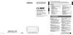
Via ETHERNET Connector with Power Over Ethernet
This requires the optional POE module be installed on the Color LCD and an IEEE802.3af Ethernet power
injector cabled to the ETHERNET jack on the display.
PWR128RA 19W Power Over Ethernet Injector
The connection supports Power Over Ethernet (POE) if the optional POE module is installed on the
controller and can be used to power the display with remote power injection. The POE support is
IEEE802.af compliant and provides a Class 0 signature. Both DC power on Spares (mode B) and DC power
on Data (mode A) operation is supported:
ETHERNET
Pin #
1
2
3
4
5
6
7
8
POE DC Power on Spares
MDI Signal
MDIX Signal
TX+
TXRX+
PSE+
PSE+
RXPSEPSE-
Copyright©2010-2014 by ACS, Sarasota, Florida
RX+
RXTX+
PSE+
PSE+
TXPSEPSE-6-
POE DC on Data
MDI Signal
MDIX Signal
TX+ PSE+
TX- PSE+
RX+ PSE-
RX+ PSE+
RX- PSE+
TX+ PSE-
RX- PSE-
TX- PSE-
ALL RIGHTS RESERVED
ACS Color 320 x 240 LCD Display Terminal User’s Manual
11 September 2014
SERIAL Connector
The display can function as either a RS-232 DTE (Data Terminal Equipment) or RS-232 DCE (Data
Communications Equipment) device. There is a jumper block site on the controller labeled JB1 that can be
used to reverse the pins of the signals pairs TxD, RxD and RTS, CTS on the SERIAL connector to
accomplish this change.
DB-9P Signals
Connection to the SERIAL connector requires a female DB-9S mating connector. The following signals
appear on the male SERIAL DB-9P connector:
PIN
SERIAL DB-9P Connector
1
2
3
4
5
6
7
8
9
DCE
Signal
JB1 as DCE
Direction
DTE
Signal
JB1 as DTE
Direction
RS-485 BRS-232 TxD
RS-232 RxD
I/O
OUT
IN
RS-485 BRS-232 RxD
RS-232 TxD
I/O
IN
OUT
GND
RS-485 A+
RS-232 CTS
RS-232 RTS
+12-15VDC
PWR
I/O
IN
OUT
PWR
GND
RS-485 A+
RS-232 RTS
RS-232 CTS
+12-15VDC
PWR
I/O
OUT
IN
PWR
JB1
Copyright©2010-2014 by ACS, Sarasota, Florida
RS-232
DCE
JB1
DTE
JB1
RS-485
JB1 Configuration Jumpers
JB1
-7-
ALL RIGHTS RESERVED
ACS Color 320 x 240 LCD Display Terminal User’s Manual
11 September 2014
RS-232 Connection to PC
The PC is configured as a DTE device. A one-to-one, female DB-9S to DB-9S cable can be used to connect
the PC communication port to the Color LCD SERIAL connector when the Color LCD is configured as
DCE. Only four wired connections are required.
The RTS connection is for optional flow control of the transmit data to the display to prevent over-flowing
the display input buffer at higher baud rates. It requires disabling the RS-485 enable in the display
configuration and implementation of flow control on the host device supplying the data to the display.
RS-232 LCD (JB1 jumpered as DCE) to PC (DTE)
The Color LCD can be connected with a one-to-one cable between the display and host PC when JB1 is
configured for DCE:
Female
Female
(To LCD) From Back!
(To PC) From Back!
5
6
1
9
5
6
DCE
+12 - +15VDC
2 - TxD
3 - RxD
8 - RTS (optional)
5 - GROUND
9 - POWER
JB1
GND
1
9
2 - RxD
3 - TxD
8 - CTS (optional)
5 - GROUND
Power
Supply
Copyright©2010-2014 by ACS, Sarasota, Florida
-8-
ALL RIGHTS RESERVED
ACS Color 320 x 240 LCD Display Terminal User’s Manual
11 September 2014
RS-232 LCD (JB1 jumpered as DTE) to PC (DTE)
The Color LCD can be connected with a null modem cable (or one-to-one cable with null modem adaptor)
between the display and host PC when JB1 is configured for DTE:
Female
Female
(To LCD) From Back!
(To LCD) From Back!
1
1
5
9
6
DTE
+12 - +15VDC
3 - RxD
2 - TxD
7 - RTS (optional)
5 - GROUND
9 - POWER
JB1
GND
6
5
9
2 - RxD
3 - TxD
8 - CTS (optional)
5 - GROUND
Power
Supply
RS-485 Connection
The LCD display can be used with RS-485 serial connections. The RS-485 Enable configuration item must
be turned on to control when the driver is enabled on the bus:
SERIAL
Pin #
6
1
5
9
Power Supply
LCD SIGNAL
GND
+12 → +15VDC
A+
BGND
+12 → +15VDC
NOTE: Be sure to connect both the Ground of the PC or Host computer and the Ground of your +12
→ +15VDC Power supply together!
The RS-485 A+ and B- signals are terminated with a 100 ohm resistor between them. In addition, there is a
10K pull-up resistor on the A+ signal to +3.3v and a 10K pull-down resistor on the B- signal to Ground, to
put the received data line in an idle state when there is no connection.
Copyright©2010-2014 by ACS, Sarasota, Florida
-9-
ALL RIGHTS RESERVED
ACS Color 320 x 240 LCD Display Terminal User’s Manual
11 September 2014
USB Connector
The ColorLCD can be connected as a USB peripheral device. A standard micro USB B receptacle
connector is provided and it can be connected to a PC using a standard USB-A to micro USB B cable. The
ColorLCD can be configured to function as either a USB flash drive or USB serial device. When configured
as a flash drive (the default) the ColorLCD SD card appears as a USB drive on the host PC and supports
file transfers. When configured as a serial device the ColorLCD sends and receives serial data as if
connected to the RS-232 port.
DEVICE
Pin #
Signal
Name
1
2
3
4
5
VBUS
DD+
ID
GND
Description
USB Power +4.5v
Data Data +
Identification (nc)
Ground
A ColorLCD.inf file is available that identifies the Color LCD as a virtual serial port device that implements
the Communications Device Class. (A Linux USB CDC configuration file is also available)
WARNING: Do not install the USB_POWER jumper if powering the display through the SERIAL
connector or external Ethernet power injection module. High voltage will be injected back through
your USB cable to the host computer.
Connect the USB A to Micro B cable to the Color LCD DEVICE connector. Connect the other end of the
cable into a USB port on your PC.
DEVICE
ColorLCD.inf
PC
USB
ACS Color 320x240
LCD
USB A
Micro B
Cable
Windows will indicate that it has found new hardware and will eventually prompt for the location of a
driver for the Color LCD. Browse to the location of the ColorLCD.inf file that you have downloaded and
select it. Windows should now finish installing the new hardware and it should be ready to use. The COM
port identifier that Windows will assign to the Color LCD will depend upon what other communications
devices are present in the system and can be determined using the Device Manager.
Copyright©2010-2014 by ACS, Sarasota, Florida
- 10 -
ALL RIGHTS RESERVED
ACS Color 320 x 240 LCD Display Terminal User’s Manual
11 September 2014
Ethernet Connector
The LCD display can be connected as an Ethernet device. A standard RJ-45 connector is provided and it
can be connected to a network with a standard Ethernet cable – either straight or crossover, detection and
correction is automatic via HP Auto MDI/MDI-X configuration. The network speed can be either 10 or 100
mbps with auto link negotiation. A link activity indicator is provided on the ETHERNET jack.
Network
PC
ETHERNET
ACS Color 320x240
LCD
Hub / Switch
ETHERNET
Patch
Cable
Patch
Cable
Optional
Power
Injection
Patch
Cable
The LCD display supports a configurable MAC address and configurable static IP address and IP mask.
Communication is performed using TCP/IP Raw Sockets with a configurable port address.
Copyright©2010-2014 by ACS, Sarasota, Florida
- 11 -
ALL RIGHTS RESERVED
ACS Color 320 x 240 LCD Display Terminal User’s Manual
11 September 2014
How the Communication Works
The RS-232 SERIAL connection is essentially always connected – even if no physical connection is
present.
The USB connection is ‘connected’ when the cable is plugged into a host PC where the driver has been
installed and the display is configured for USB Mode: SERIAL.
The ETHERNET connection is ‘connected’ when the display has been connected to the network and a
TCP/IP raw sockets link has been established.
Incoming data from each of the three sources are combined asynchronously in parallel into the display
protocol that is running.
Any output that the display protocol generates is copied to all three outputs synchronously. If a connected
output queue fills up, the other outputs are delayed until the full queue has space available - so the slowest
connected output limits the output data rate to all of the outputs.
Note that some USB hosts will stop responding to the USB connection if it is connected and there is no
application running to receive the incoming data – stopping the output data to all of the outputs.
queue
USB
connection
queue
Connected
SERIAL
connection
Connected
Here’s a diagram:
ETHERNET
connection
queue
queue
queue
queue
Display
Protocol
Copyright©2010-2014 by ACS, Sarasota, Florida
- 12 -
ALL RIGHTS RESERVED
ACS Color 320 x 240 LCD Display Terminal User’s Manual
11 September 2014
Speaker Connector
The following signals appear on the two pin KK-100 SPKR connector:
PIN
SIGNAL
1
2
Speaker +
Speaker -
Mating Connector: KK-100 0.1” 2 position
microSD Card Connector
There are two slots for use of a microSD memory card – one along the upper left-hand edge of the display,
and the other on the display controller board. These two slots are parallel – there can only be a single
microSD card installed in either slot at the same time. All card accesses are performed in SPI mode using
the following signals:
uSD Pin #
1
2
3
4
5
6
7
8
Signal Name
DAT2 / NC
CD / DAT3 / CSCMD / DI
VDD
CLK
VSS
DAT0 / DO
DAT1 / RSV
Description
No connection
Chip Select (active low)
Data Input
Power (+3.3v)
Clock
Ground
Data Output
No connection
MicroSD cards of Standard Capacity (SDSC or SD, 1MB to 4GB) and High Capacity (SDHC, 2GB to
32GB) are supported.
Copyright©2010-2014 by ACS, Sarasota, Florida
- 13 -
ALL RIGHTS RESERVED
ACS Color 320 x 240 LCD Display Terminal User’s Manual
11 September 2014
Startup
When power is applied or the ACS Color LCD 320x240 Display is reset, the controller initializes the
display, turns on the backlight, then initializes the non-volatile memory, keypad, serial communications and
touch screen. Next, if the touch screen reports that it has a continuous touch, the coordinate of the touch
location is used to force the display into one of four startup modes depending upon which quadrant is being
touched:
Touchscreen
Calibration
Diagnostics
Configuration
Settings
Program
Resource
Flash
If there is no touch held in any quadrant, the display finishes powering up:
Configuration Settings Mode
In Configuration Settings mode, the touch keypad is used to adjust or default User Configuration settings. In
this mode, the touch keypad is displayed, and the ↑ and ↓ keys are used to scroll between configuration
items, one at a time. Let’s try it. Press and release the down arrow once. The screen shows the Protocol:
setting.
Notice that the fine print legend under the setting and above the keypad indicates that the ← and → keys
can also be used to scroll between settings. Try scrolling between the various settings and notice how the
settings wrap around after the End Of Config: 0 setting is reached.
Copyright©2010-2014 by ACS, Sarasota, Florida
- 14 -
ALL RIGHTS RESERVED
ACS Color 320 x 240 LCD Display Terminal User’s Manual
11 September 2014
The legend indicates that you can Edit a setting by pressing the Enter key. Try it – scroll to the Protocol:
setting and press the Enter key. The setting highlights to show that it is being edited and the legend changes:
Try changing the setting using the arrow keys. Note that the display supports five different Protocols and
that the setting value doesn’t wrap around. You can Save the setting at any time by pressing the Enter key
again. You can also default the individual setting when editing it by pressing the * key. The Default this
Setting question appears:
Some settings allow numeric entry of a new value via the number keys.
The legend also indicates that we can default all of the settings – probably a good idea so we start with a
clean slate. Press and release the * key. The Default ALL Settings question appears:
If you press any key other than the # key, the question is answered NO and all the settings will not be
defaulted.
Press and release the # key to answer yes. The settings are defaulted and the settings screen reverts to the
first setting.
Copyright©2010-2014 by ACS, Sarasota, Florida
- 15 -
ALL RIGHTS RESERVED
ACS Color 320 x 240 LCD Display Terminal User’s Manual
11 September 2014
Touch Screen Calibration Mode
When the screen is held touched in this quadrant during power-up, the LCD enters the Touch Screen
calibration process.
Incorrect entry of the touch screen coordinates during calibration can result in the inability of the touch
screen to function properly and require that the touch screen calibration be defaulted and re-attempted. The
protective plastic covering should be removed before attempting calibration.
Calibration is a six step process. A soft pointed stylus should be used to touch each point in sequence for
improved accuracy. As each point is touched, the display computes and displays the alignment coefficients.
After the last point is touched, the display shows a Save button and allows testing the alignment by showing
touches on the screen. When the Save button is pressed the coefficients are saved to non-volatile memory.
Further touch screen activity is then compensated by the saved coefficients so that touch screen coordinates
align with display pixel locations.
1 - First Corner
2 - Second Corner
3 - Third Corner
4 - Fourth Corner
5 - Test and Save if OK
6 - Calibration done
Copyright©2010-2014 by ACS, Sarasota, Florida
- 16 -
ALL RIGHTS RESERVED
ACS Color 320 x 240 LCD Display Terminal User’s Manual
11 September 2014
Diagnostics Mode
When the screen is held touched in this quadrant during power-up, the LCD enters the Diagnostics Mode.
In Diagnostics Mode, the display alternates between drawing a grid and color bars, toggles the backlight on
and off, produces an intermittent tone and shows the status of any touch screen touch interaction:
Grid with Touch Coordinates
Color Bars
Program Resource Flash
When the screen is held touched in this quadrant during power-up, the LCD enters the Program Resource
Flash Mode.
The Color LCD uses a serial flash memory to optionally hold fonts and other graphics that it can display. In
order to program the contents of this flash an external programming utility is used in conjunction with the
display operating in this mode.
1.
Start the SPIBOOT programming utility.
2.
Select the hex file containing the resources to be programmed.
3.
Click the SPIBOOT Program button to start the resource programming.
Copyright©2010-2014 by ACS, Sarasota, Florida
- 17 -
ALL RIGHTS RESERVED
ACS Color 320 x 240 LCD Display Terminal User’s Manual
11 September 2014
User Configuration
Entering User Configuration
User configuration can be entered in two ways:
1.
Pressing on the Lower Left touch screen quadrant during power-up or Reset.
2.
Shorting EXP connector pin 7 to EXP pin 8 during power-up or Reset.
To enter the User configuration screen using the quadrant method:
1.
Press and hold the lower-left quadrant of the screen:
Touchscreen
Calibration
Diagnostics
Configuration
Settings
Program
Resource
Flash
2.
Press and release the RESET button or power cycle the display
3.
Release the lower-left quadrant of the screen.
To enter the User configuration screen using the second jumper method:
1.
Remove power, or hold the RESET button
2.
On the EXP connector connect pin 7 to pin 8 using a jumper shunt:
EXP
1
3.
Power up the display, or release the RESET button if power was not removed.
4.
The display should initialize and default the Non Volatile Memory (configuration settings).
The Configuration Settings screen should appear.
5.
Remove the EXP connector pin 7 to pin 8 jumper from step 2.
Follow the on screen soft menus to edit, select, and edit the configuration values as required.
NOTE: Some configuration setting changes will not take effect until the display is Reset.
Copyright©2010-2014 by ACS, Sarasota, Florida
- 18 -
ALL RIGHTS RESERVED
ACS Color 320 x 240 LCD Display Terminal User’s Manual
11 September 2014
Configuration Settings
#
00
01
02
03
04
05
06
07
08
09
10
11
12
13
14
15
16
17
18
19
20
21
22
23
24
25
26
27
28
29
30
31
32
33
34
35
36
37
38
39
40
41
42
43
44
45
46
47
48
49
50
51
52
53
54
55
56
Setting
Firmware Version
Protocol
Serial Baud Rate
Serial Data Bits
Serial Stop Bits
Serial Parity
RS485 Mode
USB Mode
ANSI Line Wrap
ANSI Add LF to CR
ANSI Add CR to LF
ANSI Local Echo
Display Comm Addr
Backlight on Recv
Backlight on Key
Backlight Timeout
Backlight On Level
Backlight Off Level
Send Key Opens
Power Up Disp Logo
Power Up Disp Setng
Auto Clear Disp Sec
Auto Clear DispLogo
Key Beep Enable
Key Beep Frequency
Key Beep Secs/50
TPad in SOH Raw
TPad Show Up Left-X
TPad Show Up Left-Y
TPad Show Lo Right-X
TPad Show Lo Right-Y
Power Up Quad Detect
TPad Style
TPad Scheme
PS/2 Enable
MAC Address
Use Static IP
IP Address
IP Mask
Router IP Address
FTP Server Port
VNC Server Port
HTTP Server Port
TCP/IP Raw Port
NTP Server
NTP Client Port
Local Time Zone
Daylight Savings
Serial Number
Volume
Art-Net IP Port
Art-Net Net
Art-Net Sub-Net
Art-Net Universe
Art-Net Target IP
End of Config
NV Status Byte
Description
= version # of firmware
0 = ANSI (default), 1 = SOH128Mono, 2 = SOH320Mono, 3 = SOH320Color, 4 = ACS Basic
1200, 2400, 4800, 9600 (default), 19200, 38400, 57600
7, 8 (default)
1 (default), 2
NONE (default), EVEN, ODD
None (default), Primary, Secondary
SD Card (default), Serial port
0 = no wrap (default), 1 = ANSI lines exceeding screen width wrap to next line
0 = CR (default), 1 = incoming CR replaced by CR/LF pair
0 = LF (default), 1 = incoming LF replaced by CR/LF pair
0 = no echo (default), 1 = echo
0 = no address (default), xx = display’s address for SOH/ETX protocol
0 = disabled, 1 = backlight on for time when characters received
0 = disabled, 1 = backlight on for time when switch pressed
= number of seconds backlight stays lit (default = 30)
0 = off, 12 = default, 15 = full brightness
0 = off, 5 = default, 15 = full brightness
0 = no (default), 1 = yes
0 = no logo upon reset, 1 = display graphic page 0 (logo) upon reset (default)
0 = no settings shown upon reset, 1 = display settings screen upon reset (default)
= number of seconds before display clears (default = 0, off)
= number of seconds before logo clears (default = 0, off)
0 = disabled (default), 1 = enabled
262Hz, 440Hz, 880Hz, 1397Hz (default), 1760Hz, 2093Hz, 3520Hz
= duration of key beep in fiftieths of a second (default = 12)
= Touch Keypad characters sent outside of SOH/ETX protocol
= Touch Keypad Show upper left X coordinate (0 – 319) (default=270)
= Touch Keypad Show upper left Y coordinate (0 – 239) (default=0)
= Touch Keypad Show upper left x coordinate (0 – 319) (default=319)
= Touch Keypad Show upper left x coordinate (0 – 239) (default=48)
= 0 no touchscreen quadrant detect upon reset, 1 = detect touchscreen quadrant held upon reset (default)
= NONE, QWERTY, NUMERIC, QWERTY TOP, NUMERIC TOP
= RED, GREEN, BLUE, GRAY 25%, GRAY 50%
0 = disabled (default), 1 = enabled (requires external adaptor on EXP)
= 02:01:23:45:67:89 (default)
= 0-DHCP client, 1-static IP (default)
= 192.168.1.200 (default)
= 255.255.255.0 (default)
= 192.168.1.1 (default)
= 21 (default)
= 5900 (default)
= 80 (default)
= 23 (default)
= 192.168.1.1 (default)
= 123 (default)
= -5 hours from UTC (default)
0 = no (default) adds one hour to received NTP time
00000000 (default)
Last volume setting (not currently implemented)
6454
0 (default) – 127
0 (default) – 15
0 (default) – 15
255.255.255.255 (default)
= end of configuration items placeholder
= NV status byte (default = 227)
Note that if you disable the Power Up Quad Detect you will have to use a hardware jumper to force the
display into the Configuration Settings screen on power-up.
Copyright©2010-2014 by ACS, Sarasota, Florida
- 19 -
ALL RIGHTS RESERVED
ACS Color 320 x 240 LCD Display Terminal User’s Manual
11 September 2014
The built-in HTTP configuration server is accessed using a web browser to access the ColorLCD’s
URL: http://192.168.1.200/config.cgi. The following built-in configuration page is displayed:
Touch Screen
The ACS LCD320x240 display is equipped with a four wire resistive touch screen. Touch event coordinates
may be reported to the host computer. An optional pop-up touch keypad may be displayed to allow
interactive data entry. The calibration data to align the touch screen coordinates with the display is stored in
non-volatile memory on the display.
Copyright©2010-2014 by ACS, Sarasota, Florida
- 20 -
ALL RIGHTS RESERVED
ACS Color 320 x 240 LCD Display Terminal User’s Manual
11 September 2014
Touch Keypad
A touch keypad is also available. The touch pad overlays graphics or text underneath. There are five
available styles: QWERTY, QWERTY TOP, NUMERIC, NUMERIC TOP and CONFIGURATION.
The touch pad appears on the display when a calibrated touch screen is tapped within a designated pop-up
box. The location and size of this pop-up box is configurable and defaults to a small box at the lower right
of the screen. It may be disabled by configuring the designated pop-up box coordinates to all zeroes or by
selecting a TPad Style of NONE. The touch pad can also be controlled by receipt of serial commands in
SOH/ETX protocol mode.
Here are the layouts of the various touch pads. Notice that with this configured TPad Scheme (RED) the
keys highlight when pressed:
QWERTY un-shifted
QWERTY shifted
QWERTY top, un-shifted
NUMERIC
NUMERIC top
CONFIGURATION
When the display is operating in SOH/ETX protocol mode, the keys that are touched are sent as Keypad
Closed (‘K’) response messages. See the Keypad Closed Response in the SOH/ETX Modes section for
details.
Copyright©2010-2014 by ACS, Sarasota, Florida
- 21 -
ALL RIGHTS RESERVED
ACS Color 320 x 240 LCD Display Terminal User’s Manual
11 September 2014
When the display is operating in ANSI mode, the keys are sent via the serial connection as ASCII
characters.
When the display is operating in ACS Basic mode, the keys are presented to the Basic interpreter as if they
were received from a serial connection.
Note that the small key size on the QWERTY keypads may require the use of a stylus for accurate entry.
Copyright©2010-2014 by ACS, Sarasota, Florida
- 22 -
ALL RIGHTS RESERVED
ACS Color 320 x 240 LCD Display Terminal User’s Manual
11 September 2014
Serial Flow Control
CFSound firmware provides optional support for flow control of transmit data to the player to prevent
overflowing the input buffer at higher baud rates.
The CFSound will assert its RTS signal on power-up and whenever there is room in its input buffer.
The CFSound will de-assert its RTS signal whenever the input buffer is at 90% of its 1024 byte capacity or
higher.
It will re-assert its RTS signal whenever the input buffer is below 80% capacity.
The host device that the CFSound is connected to should monitor the RTS signal, typically by connecting it
to the host’s CTS input, and only send transmit data to the player when the signal is asserted.
Without flow control it is possible to overrun the CFSound input buffer at baud rates above 9600 baud.
Symptoms of input buffer overflow include missing or incorrectly displayed data or commands.
RS-485 Driver Enable
CFSound firmware provides configurable support for enabling the RS-485 transceiver to operate in a halfduplex mode. This allows multiple devices to exist on a multi-drop bus with devices receiving from the bus
when they are not transmitting.
The player will enable its transceiver driver whenever it needs to transmit data, then it will disable the
driver after the data is fully transmitted.
Enabling this option in the configuration menu overrides the Serial Flow Control via RTS above as it uses
the RTS signal to control the RS-485 driver enable.
Copyright©2010-2014 by ACS, Sarasota, Florida
- 23 -
ALL RIGHTS RESERVED
ACS Color 320 x 240 LCD Display Terminal User’s Manual
11 September 2014
Display Operating Modes
The display supports five different operating modes selectable by the Protocol configuration item:
Protocol
ANSI Mode
SOH128Mono Mode
SOH320Mono Mode
SOH320Color Mode
ACS Basic Mode
Description
ANSI terminal emulation with UTF-8 support
ACS LCD 128x64 emulation
ACS LCD 320x240 emulation
ACS Color LCD 320x240
ACS Basic programmable
These different operating modes are further defined in the following sections.
ANSI Mode
The ANSI subset protocol allows the display to be used as a limited ANSI terminal with scrolling. The
display consists of 20 lines of 45 characters shown using a fixed pitch 6 x 10 pixel font that is drawn in a 7
x 12 pixel matrix. The display supports the concept of a ‘cursor’, which is displayed as a blinking underline,
and represents the insertion point on the display where the next printable character that is received will be
placed.
The following ANSI characters and commands are supported:
Displayed Characters
The ANSI mode supports UTF-8 character coding. Receipt of byte values of printable US ASCII characters
(32 decimal / 20 hex through 126 decimal / 7E hex) displays those characters. Extended characters may be
displayed using a multi-byte UTF-8 sequence. (See the Displayed Characters appendix for details)
Receipt of these printable characters cause the display to show the character on the screen at the current
cursor location, and then move the cursor right to the next position. Escape character sequences may be
used to pre-position the cursor, clear one or more lines and/or set the coloring for subsequently displayed
text.
There is a User Configuration setting that will automatically wrap the cursor to the beginning of the next
line, if required, scrolling up if the cursor was on the last line.
BELL
Value (ASCII 7 decimal / 07 hex) Receipt of this character causes the display to produce a 1KHz tone for
0.2 seconds.
Backspace (BS)
Value (ASCII 8 decimal / 08 hex) Receipt of this character causes the display to move the cursor one
position to the left.
Horizontal Tab (HT)
Value (ASCII 9 decimal / 09 hex) Receipt of this character causes the display to move the cursor right to
the next tab stop. Moving past the rightmost tab stop causes the cursor to move to the beginning of the
following line with display scrolling up if the cursor was on the last line. There are 9 tab stops per line at
positions 4, 8, 12, 16, 20, 24, 28, 32 and 36.
Copyright©2010-2014 by ACS, Sarasota, Florida
- 24 -
ALL RIGHTS RESERVED
ACS Color 320 x 240 LCD Display Terminal User’s Manual
11 September 2014
Line Feed (LF)
Value (ASCII 10 decimal / 0A hex) Receipt of this character causes the display to move the cursor down to
the next line in the same column. The display will scroll up if the cursor was on the last line. Lines scrolled
off the top of the screen are discarded. There is a User Configuration setting that will automatically add
receipt of a Carriage Return (CR) character after a line feed if required.
Vertical Tab (VT)
Value (ASCII 11 decimal / 0B hex) Receipt of this character causes the display to move the cursor down to
the next line in the same column. The display will scroll up if the cursor was on the last line.
Form Feed (FF)
Value (ASCII 12 decimal / 0C hex) Receipt of this character causes the display to move the cursor down to
the next line in the same column. The display will scroll up if the cursor was on the last line.
Carriage Return (CR)
Value (ASCII 13 decimal / 0D hex) Receipt of this character causes the display to move the cursor left to
the first column on the current line. There is a User Configuration setting that will automatically add receipt
of a Line Feed (LF) character after a carriage return if required.
Cancel (CAN)
Value (ASCII 24 decimal / 18 hex) Receipt of this character causes the display to abort any escape
sequence that may be in process. No other action is taken.
Escape (ESC)
Value (ASCII 33 decimal / 1B hex) Receipt of this character causes the display to attempt to decode one or
more of the following characters as a control or escape sequence that will affect the display.
Reset Display (ESC c)
Values (ASCII 33, 99 decimal / 1B, 63 hex) Receipt of this character sequence causes the display to clear,
and the cursor position to move to the upper left corner.
Cursor Down (ESC D)
Values (ASCII 33, 68 decimal / 1B, 44 hex) Receipt of this character sequence causes the display to move
the cursor down to the next line in the same column. The cursor will not move and the display will not scroll
up if the cursor was on the last line.
Cursor Down to column 1 (ESC E)
Values (ASCII 33, 69 decimal / 1B, 45 hex) Receipt of this character sequence causes the display to move
the cursor down to the next line and the first column. The cursor will not move and the display will not
scroll up if the cursor was on the last line.
Cursor Up (ESC M)
Values (ASCII 33, 77 decimal / 1B, 4D hex) Receipt of this character sequence causes the display to move
the cursor up to the previous line in the same column. The cursor will not move if the cursor was on the first
line.
Copyright©2010-2014 by ACS, Sarasota, Florida
- 25 -
ALL RIGHTS RESERVED
ACS Color 320 x 240 LCD Display Terminal User’s Manual
11 September 2014
ANSI Escape Sequences (ESC [ )
Values (ASCII 33, 91 decimal / 1B, 5B hex) Receipt of this character sequence causes the display to
attempt to decode one or more of the following characters as an ANSI control sequence. These sequences
can have 1 or 2 parameters that are expressed as decimal numbers separated by a semicolon. These are
represented by the italic letters in the sequence description.
Cursor Up n lines (ESC [ n A)
Values (ASCII 33, 91, 48-57, 65 decimal / 1B, 5B, 30-39, 41 hex) Receipt of this character sequence causes
the display to move the cursor up ‘n’ (default n=1) lines in the same column. The cursor will not move up past
the first line in the display.
Cursor Up n lines to column 1 (ESC [ n F)
Values (ASCII 33, 91, 48-57, 70 decimal / 1B, 5B, 30-39, 46 hex) Receipt of this character sequence causes
the display to move the cursor up ‘n’ (default n=1) lines and to the first column. The cursor will not move up
past the first line in the display.
Cursor Down n lines (ESC [ n B)
Values (ASCII 33, 91, 48-57, 66 decimal / 1B, 5B, 30-39, 42 hex) Receipt of this character sequence causes
the display to move the cursor down ‘n’ (default n=1) lines in the same column. The cursor will not move past
the bottom line in the display and the display will not scroll up.
Cursor Down n lines to column 1 (ESC [ n E)
Values (ASCII 33, 91, 48-57, 69 decimal / 1B, 5B, 30-39, 45 hex) Receipt of this character sequence causes
the display to move the cursor down ‘n’ (default n=1) lines and to the first column. The cursor will not move
past the bottom line in the display and the display will not scroll up.
Cursor Right n characters (ESC [ n C)
Values (ASCII 33, 91, 48-57, 67 decimal / 1B, 5B, 30-39, 43 hex) Receipt of this character sequence causes
the display to move the cursor right ‘n’ (default n=1) characters on the same line. The cursor will not move
past the end of the current line.
Cursor Left n characters (ESC [ n D)
Values (ASCII 33, 91, 48-57, 68 decimal / 1B, 5B, 30-39, 44 hex) Receipt of this character sequence causes
the display to move the cursor left ‘n’ (default n=1) characters on the same line. The cursor will not move past
the beginning of the current line.
Move cursor to n (ESC [ n G)
Values (ASCII 33, 91, 48-57, 71 decimal / 1B, 5B, 30-39, 47 hex) Receipt of this character sequence causes
the display to move the cursor to column ‘n’ (default n=1) on the current line. The cursor will not move past
the beginning or end of the current line.
Move cursor to r, c (ESC [ r ; c H)
Values (ASCII 33, 91, [[48-57], 59, [48-57]], 72 decimal / 1B, 5B, [[30-39], 3B, [30-39]], 48 hex) Receipt
of this character sequence causes the display to move the cursor to row ‘r’, column ‘c’. The value for ‘r’
ranges from 1 – 20 ((default r=1), the value for ‘c’ ranges from 1 – 44 (default c=1).
Erase all or part of display (ESC [ n J)
Values (ASCII 33, 91, 48-50, 74 decimal / 1B, 5B, 30-32, 4A hex) Receipt of this character sequence
causes part or all of the display to clear. If ‘n’ = 0 (default), the display is cleared from the cursor position to
Copyright©2010-2014 by ACS, Sarasota, Florida
ALL RIGHTS RESERVED
- 26 -
ACS Color 320 x 240 LCD Display Terminal User’s Manual
11 September 2014
the end. If ‘n’ = 1, the display is cleared from the beginning to the cursor position. If ‘n’ = 2 the entire
display is cleared, and the cursor is moved to the upper left (0, 0).
Erase all or part of line (ESC [ n K)
Values (ASCII 33, 91, 48-50, 75 decimal / 1B, 5B, 30-32, 4B hex) Receipt of this character sequence
causes part or all of the line that the cursor is on to clear. If ‘n’ = 0 (default), the line is cleared from the
cursor position to the end of the line. If ‘n’ = 1, the line is cleared from the beginning to the cursor position.
If ‘n’ = 2 the entire line is cleared. The position of the cursor is not affected by this command.
Save cursor position (ESC [ s)
Values (ASCII 33, 91, 114 decimal / 1B, 5B, 73 hex) Receipt of this character sequence causes the display
to save the current cursor position.
Restore cursor position (ESC [ u)
Values (ASCII 33, 91, 116 decimal / 1B, 5B, 75 hex) Receipt of this character sequence causes the display
to restore the previously saved cursor position.
Query (ESC [ 6 n)
Values (ASCII 33, 91, 54, 110 decimal / 1B, 5B, 36, 6E hex) Receipt of this character sequence causes the
display to report the current cursor position as <ESC> [ row ; column R. The ‘n’ character is actually part of
the command and is not replaced by a number. The value for row is 1 – 20, the value for column is 1 – 44.
Select Graphic Rendition (ESC [ n [;k] m)
Values (ASCII 33, 91, xx, xx decimal / 1B, 5B, xx, xx hex) Receipt of these character sequences cause the
display to use different coloring for subsequently displayed characters. (default n=0)
Code
0
30
31
32
33
34
35
36
37
40
41
42
43
44
45
46
47
Copyright©2010-2014 by ACS, Sarasota, Florida
Effect
Reset / Normal
Text Color Black
Text Color Red
Text Color Green
Text Color Yellow
Text Color Blue
Text Color Magenta
Text Color Cyan
Text Color White
Background Color Black
Background Color Red
Background Color Green
Background Color Yellow
Background Color Blue
Background Color Magenta
Background Color Cyan
Background Color White
- 27 -
ALL RIGHTS RESERVED
ACS Color 320 x 240 LCD Display Terminal User’s Manual
11 September 2014
SOH/ETX Modes
The SOH/ETX protocols allow full control of the display features and functionality, but require that the host
computer properly format sequences of commands using the protocol to control the display, and interpret a
formatted response to receive status and data from the display.
The SOH/ETX protocol starts each command or response with a single ASCII Start of Header control
character = 0116 or CTRL-A, represented herein as <SOH> and ends each command with a single ASCII
End of Text control character = 0316 or CTRL-C, represented herein as <ETX>.
Command or Response data arguments are sent as ASCII Hex strings one to four characters in length or as
printable ASCII characters. Multiple fields may be delineated by embedded ASCII separator control
characters depending upon the actual display mode.
The SOH128Mono and SOH320Mono Modes are emulated to provide an upgrade path from earlier
displays. To perform ‘Printing’ in these modes requires specific embedded font resources (.efnt) to be
available either in the on-board serial EEProm or via a Resources.bin file on the microSD card. See the
SOH320Color, Resources section for more information.
In the SOH/ETX command / response descriptions that follow there are spaces shown between the different
parts of each command.
THE EMBEDDED SPACES IN THE FOLLOWING DESCRIPTIONS ARE FOR CLARITY ONLY,
ARE NOT PART OF THE TRANSMITTED / RECEIVED COMMANDS AND SHOULD NOT BE
INCLUDED !
Display Addressing
If you set the User Configuration Setting ‘Display Comm Addr’ item to a value greater than zero, you must
take the following into consideration when using the SOH/ETX protocol:
Commands sent to the display must have a two-digit ASCII hex address sent between the leading <SOH>,
and the following command letter. If the display’s address does not match the address in the command, it
will ignore the command. If a command is sent with an address of zero, it is considered a broadcast
message, and all displays with an address set will display the command. This allows multiple displays to be
updated via a single RS-232 interface.
Keystroke responses received from displays with their address greater than zero, will have the displays
address in two digit ASCII hex between the <SOH> and the “K” or “k”. Note that the return RS-232 RxD
signals from multiple displays would have to be wire ‘OR’ed using circuitry such as diodes that are external
to the display. (See the Multiple Display Wiring appendix)
Copyright©2010-2014 by ACS, Sarasota, Florida
- 28 -
ALL RIGHTS RESERVED
ACS Color 320 x 240 LCD Display Terminal User’s Manual
11 September 2014
SOH128Mono Mode
This display operating mode emulates most of the functions of the ACS-LCD-128x64 monochrome display.
The pixels are drawn doubled in size and there is no support for the hardware keypad overlay – it is
emulated on-screen:
The color scheme is controlled by the TPad Scheme configuration item.
The fonts required for emulating the print commands in this mode must be available as loaded resources via
the serial EEProm or microSD - Resources.bin file. If one or more are not available a default font is
substituted that will not match the requested font size or spacing. These fonts provide simulation of the
older display’s fonts and will not match them exactly:
Font #
0
1
2
3
4
5
Style
Resource Name
Small 5x7 proportional
Medium 9x15 proportional
Micro 4x5 proportional
Giant 30x55 proportional
Small 5x7 fixed
Large 18x30 proportional
AcsSoh128Small.efnt
AcsSoh128Medium.efnt
AcsSoh128Micro
AcsSoh128Giant.efnt
AcsSoh128Fixed.efnt
AcsSoh128Large.efnt
The X and Y coordinates for drawing start at 0, 0 at the upper left corner of the display:
0, 0
127, 0
Row 1 = 01 hex
Row 2 = 02 hex
Row 3 = 04 hex
Row 4 = 08 hex
Row 5 = 10 hex
Row 6 = 20 hex
Row 7 = 40 hex
Row 8 = 80 hex
0, 63
127, 63
Drawing is clipped at the coordinate boundaries of the display.
Please refer to the separate document “ACS-LCD-128x64 User’s Manual” for the serial protocol and
commands.
Copyright©2010-2014 by ACS, Sarasota, Florida
- 29 -
ALL RIGHTS RESERVED
ACS Color 320 x 240 LCD Display Terminal User’s Manual
11 September 2014
SOH320Mono Mode
This display operating mode emulates most of the functions of the ACS-LCD-320x240 monochrome
display. There is no support for a hardware keypad or input polling:
The color scheme is controlled by the TPad Scheme configuration item.
The fonts required for emulating the print commands in this mode must be available as loaded resources via
the serial EEProm or microSD - Resources.bin file. If one or more are not available a default font is
substituted that will not match the requested font size or spacing. These fonts provide simulation of the
older display’s fonts and will not match them exactly:
Font #
0
1
2
3
4
5
Style
Resource Name
Small 5x7 proportional
Medium 9x15 proportional
Micro 4x5 proportional
Giant 30x55 proportional
Small 5x7 fixed
Large 18x30 proportional
AcsSoh320Small.efnt
AcsSoh320Medium.efnt
AcsSoh320Micro
AcsSoh320Giant.efnt
AcsSoh320Fixed.efnt
AcsSoh320Large.efnt
The X and Y coordinates for drawing start at 0, 0 at the upper left corner of the display:
0, 0
319, 0
0, 239
319, 239
Drawing is clipped at the coordinate boundaries of the display.
Please refer to the separate document “ACS-LCD-320x240 User’s Manual” for serial protocol and
commands.
Copyright©2010-2014 by ACS, Sarasota, Florida
- 30 -
ALL RIGHTS RESERVED
ACS Color 320 x 240 LCD Display Terminal User’s Manual
11 September 2014
SOH320Color Mode
This display operating mode provides an extended command set for operation of the display features.
Commands are provided for drawing graphics, displaying bitmaps with transparency, printing UTF-8 text
with user-supplied fonts and receiving touchscreen interaction. There is also a higher level screen and
object model available to simplify user interaction with buttons and sliders and facilitate multiple screen
navigation.
NOTE that embedded spaces are used in the following command/response descriptions for
clarity/readability and they are NOT PART OF THE COMMANDS.
Copyright©2010-2014 by ACS, Sarasota, Florida
- 31 -
ALL RIGHTS RESERVED
ACS Color 320 x 240 LCD Display Terminal User’s Manual
11 September 2014
Quick Start
With the display powered, configured for SOH320Color Mode and connected to your PC use
Hyperterminal, TeraTerm or another terminal emulator program to exercise the display.
When you power-up or reset the display in this mode there is a resource loading status screen shown. This
screen clears and the following screen should be momentarily displayed:
This screen should also clear and leave the display blank. At this time you should see the letter R displayed
in your terminal emulator program:
The R is the display’s Reset status message. It is actually bracketed with <SOH> and <ETX> characters, but
the terminal emulator doesn’t show the non-printing characters without enabling a debug mode. The display
is now ready to accept commands.
Drawing Graphics
Let’s draw a white diagonal line across the display. Looking ahead to the Draw commands we find the
following command template for drawing a line:
Draw Line
Draws a single color line on the current draw surface between the two coordinates:
<SOH> dl XXX YYY xxx yyy CCCC <ETX>
Where:
Field
<SOH>
dl
XXX
YYY
xxx
yyy
CCCC
<ETX>
Field Name
Notes
Start of Header
Draw Line
Line Starting X Coordinate
Line Starting Y Coordinate
Line Ending X Coordinate
Line Ending Y Coordinate
Line Color
End of Text
Copyright©2010-2014 by ACS, Sarasota, Florida
- 32 -
Ctrl-A (Hex 01)
Command/modifier
3-digit ASCII Hex 000-13F
3-digit ASCII Hex 000-0EF
3-digit ASCII Hex 000-13F
3-digit ASCII Hex 000-0EF
4-digit ASCII Hex RGB565
Ctrl-C (Hex 03)
ALL RIGHTS RESERVED
ACS Color 320 x 240 LCD Display Terminal User’s Manual
11 September 2014
At the beginning of the Drawing section the screen coordinates are defined - the X and Y coordinates for
drawing start at 0, 0 at the lower left corner of the display and range to 319, 239 at the upper right corner.
The hex values of each corner coordinate are shown below each pair:
0, 239
000, 0EF
319, 239
13F, 0EF
0, 0
000, 000
319, 0
13F, 000
In the Manual Conventions at the beginning of this manual, the <SOH> and <ETX> were defined to be
printed representations of single ASCII control characters:
<SOH> Is the printed representation of a single ASCII Start of Heading character; CTRL-A, 01 decimal,
01 hex. This character delineates the start of a command or response in SOH/ETX the protocol modes. This
character may be sent from your terminal emulator by holding down the Ctrl key and pressing the A key.
<ETX> Is the printed representation of a single ASCII End of Text character; CTRL-C, 03 decimal, 03
hex. This character delineates the end of a command or response in SOH/ETX the protocol modes. This
character may be sent from your terminal emulator by holding down the Ctrl key and pressing the C key.
We should be able to draw this diagonal line by sending the following characters to the display by typing
them into your connected terminal emulator (without the spaces):
Ctrl-A dl 000 000 13F 0EF FFFF Ctrl-C
The display screen should now look like:
If your display doesn’t look like this try typing the command again making sure that you typed all of the
letters correctly and that there aren’t any spaces.
Copyright©2010-2014 by ACS, Sarasota, Florida
- 33 -
ALL RIGHTS RESERVED
ACS Color 320 x 240 LCD Display Terminal User’s Manual
11 September 2014
Now draw a red circle. Looking ahead in the manual to the Draw Circle command we find the following
command template:
Draw Circle
Draws a single color circle on the current draw surface with a radius at the center coordinates:
<SOH> dc XXX YYY RRR CCCC <ETX>
Where:
Field
Field Name
<SOH>
dc
XXX
YYY
RRR
CCCC
<ETX>
Notes
Start of Header
Draw Circle
Circle Center X Coordinate
Circle Center Y Coordinate
Circle Radius
Circle Color
End of Text
Ctrl-A (Hex 01)
Command/modifier
3-digit ASCII Hex 000-13F
3-digit ASCII Hex 000-0EF
3-digit ASCII Hex 000-13F
4-digit ASCII Hex RGB565
Ctrl-C (Hex 03)
To draw this in the center of the screen, the Center X Coordinate should be 320 / 2 = 160 = 0A0 in hex. The
Center Y Coordinate should be 240 / 2 = 120 = 078 in hex. Try using a radius of 48 = 030 in hex.
The last command parameter is the color. In the Manual Conventions at the beginning of this manual, there
is a definition for RGB565:
RGB565
Is the printed representation of a 16-bit color comprised of 5 bits of Red, 6 bits of Green and 5 bits of Blue:
15
MSB
14
13
12
11
10
9
8
Red
7
6
5
4
3
2
Green
0
LSB
1
Blue
To draw a bright red circle, the leftmost five red bits would all be ones, and the rest would be zero.
Translating these RGB565 bit fields to 4-bit hexadecimal fields:
15
MSB
14
1
1
13
12
11
10
9
8
1
1
0
0
0
Red
Binary
Hex
1
7
6
5
4
3
0
0
0
0
Green
F
8
0
2
1
0
LSB
0
0
Blue
0
0
0
So a bright red ASCII HEX RGB565 color would be F800 in hex. We should be able to draw this circle by
sending the following characters to the display by typing them into your connected terminal emulator
(without the spaces):
Ctrl-A dc 0A0 078 030 F800 Ctrl-C
The display screen should now look like:
Copyright©2010-2014 by ACS, Sarasota, Florida
- 34 -
ALL RIGHTS RESERVED
ACS Color 320 x 240 LCD Display Terminal User’s Manual
11 September 2014
Try some of the other Draw commands using different colors to see how they work.
Drawing Text
Let’s add some text. Looking ahead at the Drawing commands we find the following template for drawing
text:
Draw Text
Draws a UTF-8 text string on the current draw surface using the specified font at the coordinates:
<SOH> dt FF XXX YYY textString <ETX>
Where:
Field
Field Name
<SOH>
dt
FF
XXX
YYY
textString
<ETX>
Notes
Start of Header
Draw Text
Font Number
Text X Coordinate
Text Y Coordinate
Text to be drawn
End of Text
Ctrl-A (Hex 01)
Command/modifier
2-digit ASCII Hex 00-1F
3-digit ASCII Hex 000-13F
3-digit ASCII Hex 000-0EF
8-bit UTF-8 text string
Ctrl-C (Hex 03)
So let’s print HelloWorld in the center of the screen. We will use font number 00 which defaults to a builtin font that the display uses for diagnostics. Type the following command (without the spaces):
Ctrl-A dt 00 0A0 078 HelloWorld Ctrl-C
The display screen should now look like:
The actual font color will depend upon the configured TPad Scheme – when the display resets the fonts are
initialized from the configured, built-in scheme.
On your terminal emulator you should see a response from the dt command:
dts004F0016
Looking ahead to the Draw Text section of the manual, we can see that this is a response from the draw text
command:
This command returns a response containing the width and height of the drawn text string to facilitate
chaining /aligning subsequent text:
<SOH> dts WWWW HHHH <ETX>
Where:
Field
<SOH>
dts
Field Name
Start of Header
Draw Text Size
Copyright©2010-2014 by ACS, Sarasota, Florida
Notes
Ctrl-A (Hex 01)
Response/modifier/parameter
- 35 -
ALL RIGHTS RESERVED
ACS Color 320 x 240 LCD Display Terminal User’s Manual
Field
WWWW
HHHH
<ETX>
Field Name
11 September 2014
Notes
Drawn Text Width
Drawn Text Height
End of Text
4-digit ASCII Hex 0000-013F
4-digit ASCII Hex 0000-00EF
Ctrl-C (Hex 03)
This text is being drawn with Font #00. Fonts are a ‘resource’ used by other commands and objects and are
controlled by entries in two tables.
The first requirement for font usage is an embedded font file that is loaded into the Resource table. There
are two or more embedded fonts built-in to the display, and more can be loaded from the on-board serial
flash or micro SD card memory.
The second requirement for font usage is an entry in the Font table that links the name of the embedded font
resource with other font attributes such as color, transparency, spacing and alignment.
You can query the display for Font #00’s attributes, and then issue other commands to change them.
Looking ahead in this manual to the Query commands you can see that there are commands to Query Fonts
and Resources. The command template for a font query command is:
Query Font Item
The Query Font Item command returns a response showing the requested font item’s current value:
<SOH> qti NN <ETX>
Where:
Field
<SOH>
qti
NN
<ETX>
Field Name
Notes
Start of Header
Query Font Item
Font Number
End of Text
Ctrl-A (Hex 01)
Command/modifier/parameter
2-digit ASCII Hex 00-FF
Ctrl-C (Hex 03)
To see the attributes for Font #00 type the following Query Font Item command (without the spaces):
Ctrl-A qti 00 Ctrl-C
On the terminal emulator you should see the response from the qti command:
qt00AcsDefaultFont.efnt001600008410001110
qt00
Again, there are the bracketing <SOH> and <ETX> characters, and, in addition the individual fields of the
response are delineated by embedded <US> characters with the record ending with a <RS> character. The
end of the response is indicated by the trailing qt00 followed by the <GS> character. The terminal
emulator typically doesn’t show these non-printing control characters – some programs can.
Looking at these fields we can determine the following information about Font #00:
Field
<SOH>
qt
00
AcsDefaultFont.efnt
0016
0000
8410
0
0
1
Field Name
Value
Start of Header
Ctrl-A (Hex 01)
Query Font
Font Number
Response/modifier
Font #00
Font File Resource Name
Font Height
Font Background Color
Font Foreground Color
Name of loaded .EFNT resource
0016 = 22 pixels high
0000 = Black
8410 = Grey
Font Spacing-X
Font Spacing-Y
Font Horizontal Alignment
0 = fixed width of the font
0 = fixed width of the font
1 = Center Justify
Copyright©2010-2014 by ACS, Sarasota, Florida
- 36 -
ALL RIGHTS RESERVED
ACS Color 320 x 240 LCD Display Terminal User’s Manual
Field
1
1
0
<ETX>
11 September 2014
Field Name
Font Vertical Alignment
Background Transparency
Foreground Transparency
Value
1 = Center Justify
1 = Transparent
0 = Solid
End of Text
Ctrl-C (Hex 03)
Change font number 00 to be white foreground letters on a red background. To do this you have to change
the Font Background Color, the Font Foreground Color and the Background Transparency. Looking ahead
in this manual to the Font commands you can see that there are commands to set the Font Colors and Font
Attributes.
The command template for the command to set the Font Colors is:
Font Colors
Sets the background and foreground colors used to draw this font table entry:
<SOH> fc FF BRGB FRGB <ETX>
Where:
Field
<SOH>
fc
FF
BRGB
FRGB
<ETX>
Field Name
Notes
Start of Header
Font Color
Font Table entry number
Font Background Color
Font Foreground Color
End of Text
Ctrl-A (Hex 01)
Command/modifier
2-digit ASCII Hex 00-1F
4-digit ASCII Hex RGB565
4-digit ASCII Hex RGB565
Ctrl-C (Hex 03)
To set the background color to red and the foreground color to white type the following command (without
the spaces):
Ctrl-A fc 00 F800 FFFF Ctrl-C
The command template for the command to set the Font Attributes is:
Font Attributes
Sets the background and foreground colors used to draw this font table entry:
<SOH> fa FF X Y H V B F <ETX>
Where:
Field
<SOH>
fa
FF
Field Name
Notes
Start of Header
Font Attribute
Font Table entry number
X
Font Spacing-X
Y
Font Spacing-Y
H
Font Horizontal Alignment
V
Font Vertical Alignment
Copyright©2010-2014 by ACS, Sarasota, Florida
Ctrl-A (Hex 01)
Command/modifier
2-digit ASCII Hex 00-1F
1-digit ASCII Hex:
0 = fixed width of the font
1→E = pixels between characters
F = bounding box character width
1-digit ASCII Hex:
0 = fixed width of the font
1→E = pixels between characters
F = bounding box character width
1-digit ASCII Hex:
0 = Left Justify
1 = Center Justify
2 = Right Justify
1-digit ASCII Hex:
0 = Top Justify
- 37 -
ALL RIGHTS RESERVED
ACS Color 320 x 240 LCD Display Terminal User’s Manual
Field
11 September 2014
Field Name
Notes
B
Background Transparency
F
Foreground Transparency
<ETX>
End of Text
1 = Center Justify
2 = Bottom Justify
1-digit ASCII Hex:
0 = Solid
1 = Transparent
1-digit ASCII Hex:
0 = Solid
1 = Transparent
Ctrl-C (Hex 03)
To set the background transparency to solid (and keep the other font attributes the same type the following
command (without the spaces):
Ctrl-A fa 00 0 0 1 1 0 0 Ctrl-C
You can verify that the colors and attributes have been set by using the Query Font Item command again:
Ctrl-A qti 00 Ctrl-C
Now the response should be:
qti00qt00AcsDefaultFont.efnt0016F800FFFF001100
qt00
Looking at these fields we can verify that we changed Font #00:
Field
Field Name
<SOH>
qt
00
AcsDefaultFont.efnt
0016
F800
FFFF
0
0
1
1
0
0
<ETX>
Value
Start of Header
Ctrl-A (Hex 01)
Query Font
Font Number
Response/modifier
Font #00
Font File Resource Name
Font Height
Font Background Color
Font Foreground Color
Name of loaded .EFNT resource
0016 = 22 pixels high
F800 = Red
FFFF = White
Font Spacing-X
Font Spacing-Y
Font Horizontal Alignment
Font Vertical Alignment
Background Transparency
Foreground Transparency
0 = fixed width of the font
0 = fixed width of the font
1 = Center Justify
1 = Center Justify
0 = Solid
0 = Solid
End of Text
Ctrl-C (Hex 03)
Issue the same Draw Text command by typing the following command (without the spaces):
Ctrl-A dt 00 0A0 078 HelloWorld Ctrl-C
The display screen should now look like:
Copyright©2010-2014 by ACS, Sarasota, Florida
- 38 -
ALL RIGHTS RESERVED
ACS Color 320 x 240 LCD Display Terminal User’s Manual
11 September 2014
Try changing the other Font Attributes to see the results.
Copyright©2010-2014 by ACS, Sarasota, Florida
- 39 -
ALL RIGHTS RESERVED
ACS Color 320 x 240 LCD Display Terminal User’s Manual
11 September 2014
Clearing the Display
So, how do we clear the display? Again looking ahead to the Draw commands we don’t see a Clear subcommand, but there is a Fill. The display is cleared by filling the screen with the desired color. Here’s the
command description:
Draw Fill Flat
Fills an area of the current draw surface defined by a lower-left coordinate, width and height with a
constant color:
<SOH> dff XXX YYY WWW HHH CCCC <ETX>
Where:
Field
<SOH>
dff
XXX
YYY
WWW
HHH
CCCC
<ETX>
Field Name
Notes
Start of Header
Draw Fill Flat
Lower-left Fill X Coordinate
Lower-left Fill Y Coordinate
Fill Width
Fill Height
Fill Color
End of Text
Ctrl-A (Hex 01)
Command/modifier/parameter
3-digit ASCII Hex 000-13F
3-digit ASCII Hex 000-0EF
3-digit ASCII Hex 000-140
3-digit ASCII Hex 000-0F0
4-digit ASCII Hex RGB565
Ctrl-C (Hex 03)
To clear the screen to black, issue a Draw Fill Flat command that covers the entire screen with the color
black (0000):
Ctrl-A dff 000 000 140 0F0 0000 Ctrl-C
The screen should now be blank (black).
Copyright©2010-2014 by ACS, Sarasota, Florida
- 40 -
ALL RIGHTS RESERVED
ACS Color 320 x 240 LCD Display Terminal User’s Manual
11 September 2014
Command Structure
Commands to the display are bracketed by <SOH> and <ETX>. The requested command is designated by a
single lower-case ASCII character. The command may be modified by an additional character specifying a
sub-command, and some commands may also have one or more parameters:
<SOH> c [ m [ p … p ] ] <ETX>
Where:
Field
Field Name
Notes
<SOH>
c
m
p…p
<ETX>
Start of Header
Command designator
Command Modifier
Command Parameter(s)
End of Text
Ctrl-A (Hex 01)
Single lower-case ASCII letter
Single lower-case ASCII letter (optional)
One or more letters or ASCII Hex fields (optional)
Ctrl-C (Hex 03)
Command Responses
In this mode, commands return a response indicating success or failure. If a command would return
information, the return of that information is considered a success – otherwise a short Failure response is
returned. If a command is not expected to return any information, a small response is returned indicating the
success or failure of the command:
Success response if no results:
<SOH> <ACK> <ETX>
Failure response:
<SOH> <NAK> XX <ETX>
Where XX is the error code:
Code
02
03
04
05
06
07
08
09
0A
0B
0C
0D
0E
0F
10
11
12
13
14
15
16
18
19
Label
Unknown Command
Invalid Command Length
Unknown Command Modifier
Unknown Command Parameter
Invalid Command Value
Command Value Out of Range
Resource Not Found
Invalid File Format
File System OK
File System Not Ready
No File
No Path
Invalid File Name
Invalid Drive
Denied
Exist
Read/Write Error
Write Protected
Not Enabled
No Filesystem
Invalid Object
End of File
Disk Full
Copyright©2010-2014 by ACS, Sarasota, Florida
Notes
Not a known command character
Length of command incorrect
Not a known command modifier for this command
Not a known command parameter for this command
One or more command fields unable to be parsed
A command parameter value is out of range
Requested resource is not found in the table
JSON file can’t be loaded
Can’t read microSD card
Can’t find file on microSD card
Can’t find path on microSD card
File name or path not correct
n/u
Can’t create directory entry – disk full or file read only.
File or directory already exists
Error while reading or writing the microSD card
n/u
n/u
No FAT16 or FAT32 valid partition found
File System object invalid
File read fell short – end of file before end of read
File write fell short – disk may be full
- 41 -
ALL RIGHTS RESERVED
ACS Color 320 x 240 LCD Display Terminal User’s Manual
11 September 2014
Resources
The ACS Color LCD 320x240 uses ‘resources’ to provide fonts, bitmaps and sounds in this mode. These
resources are loaded into a ‘table’ in RAM where they can be rapidly accessed by the different commands
that require them.
This resource table can be loaded from the on-board Serial Flash or from the micro SD card upon reset, or
dynamically from the micro SD card during operation. The table is searched from the beginning when
resources are accessed, with newly added resources located at the front of the table.
Each entry in the table consists of the size of the resource, its name– including any extension, and then the
resource contents. The entire Resource Table is protected by a cyclic redundancy check value of its
contents. Dynamically added resources are added to the front of the Resource Table:
Resource Table
Table Size
Size = 16
“LcdResource”
Size of “ResourceName0{.ext}”
“ResourceName0{.ext}”
ResourceName0{.ext} Contents
Size of “ResourceName1{.ext}”
“ResourceName1{.ext}”
ResourceName1{.ext} Contents
...
Size of “ResourceNameN{.ext}”
“ResourceNameN{.ext}”
ResourceNameN{.ext} Contents
Size = 0 (end of table)
CRC16
Copyright©2010-2014 by ACS, Sarasota, Florida
- 42 -
ALL RIGHTS RESERVED
ACS Color 320 x 240 LCD Display Terminal User’s Manual
11 September 2014
Resource Commands
All resource commands start with the lower-case letter ‘r’ followed by a command modifier character
specifying the command. The remainder of the command consists of zero or more data arguments expressed
as ASCII printable characters:
<SOH> r … <ETX>
Resource Load All From Flash
Initializes then loads the Resource Table from the on-board serial EEProm. The serial EEProm must
have previously been loaded with a binary image of a valid table of resources.
<SOH> r l <ETX>
Resource Save All To Flash
Writes the current Resource Table image to the on-board serial EEProm.
<SOH> r s <ETX>
Resource Load All From File
Initializes then loads the Resource Table from a binary file image located on the microSD card.
<SOH> r < fileName <ETX>
Resource Save All To File
Saves the current Resource Table to a binary file image located on the microSD card.
<SOH> r > fileName <ETX>
Resource Add From File
Loads the resource at the beginning of the Resource Table from a file image located on the microSD
card. The subsequent resource name is the filename.
<SOH> r + fileName <ETX>
Resource Remove
Removes the named resource from the Resource Table.
<SOH> r – resourceName <ETX>
Resource File Generation
The binary resource file image can be generated by an ACS Windows utility that supports the concept of
resource generation projects (.rsrcgen XML project files). (See the appendix Resource File Generation)
Copyright©2010-2014 by ACS, Sarasota, Florida
- 43 -
ALL RIGHTS RESERVED
ACS Color 320 x 240 LCD Display Terminal User’s Manual
11 September 2014
Initial Resource Table Load
When the ACS Color LCD 320x240 is powered-up or reset, it attempts to locate and load the resource table
from several sources. This process is outlined in the following flowchart:
Reset
Initialize default
resources
Detect and
Initialize micro SD
card
Load Serial Flash
Protected
Resources
Micro SD card
good and
Resources.bin file
loaded OK ?
No
Load Serial Flash
Resources
Yes
Done
1.
The AcsDefaultFont.efnt (used for the diagnostics and keypad keys) and the AcsAnsiFont.efnt
resources are loaded from internal flash memory.
2.
The micro SD card is detected and, if present, the file system is initialized.
3.
A check is made for protected resources located at the top of the external Serial Flash memory and
they are loaded if found.
4.
If the micro SD card was detected and initialized in step 2 attempt to load the binary resources file
named: Resources.bin. If it loads and verifies then initial resource table loading is complete.
5.
If step 4 fails, attempt to load and verify the resources located at the bottom of the external Serial
Flash memory.
Copyright©2010-2014 by ACS, Sarasota, Florida
- 44 -
ALL RIGHTS RESERVED
ACS Color 320 x 240 LCD Display Terminal User’s Manual
11 September 2014
Fonts
The appearance of all text that is drawn on the display is controlled by fonts selected from a font table. The
character images are extracted from previously constructed and loaded .EFNT resources. Each table entry
holds the Font Name (.EFNT resource name), several attributes for horizontal and vertical alignment and
spacing and background/foreground colors and transparency.
The table holds 32 entries. The table entry number is used as the selector of the font for drawing and display
access.
.EFNT Resource
Resource Table
Background Color
Other resource
Foreground Color
Spacing X
Font
Table
Spacing Y
Fontfile.EFNT
Horizontal Align
Font 00
Vertical Align
Font 01
Background Transp
Font 02
Other resource
Foreground Transp
...
Other resource
...
Font 29
.EFNT Resource
Font 30
Fontfile.EFNT
Background Color
Foreground Color
Font 31
Spacing X
Other resource
Spacing Y
Horizontal Align
Vertical Align
Fontfile.EFNT
Background Transp
Foreground Transp
Font Commands
All Font commands start with the letter ‘f’ followed by a command modifier character specifying the
command. The remainder of the command consists of one or more data arguments expressed as ASCII Hex
strings or ASCII printable characters:
<SOH> f … <ETX>
There are commands to specify the font resource name, attributes and colors for each table entry, and load
or save the font table from/to a file on the microSD card.
Font Name
Sets the name of the character image resource (.EFNT) used to draw this font table entry:
<SOH> fn FF resourceName <ETX>
Where:
Field
<SOH>
fn
FF
resourceName
<ETX>
Field Name
Start of Header
Font Name
Font Table entry number
Font File Resource Name
End of Text
Copyright©2010-2014 by ACS, Sarasota, Florida
- 45 -
Notes
Ctrl-A (Hex 01)
Command/modifier/parameter
2-digit ASCII Hex 00-1F
Name of loaded .EFNT resource
Ctrl-C (Hex 03)
ALL RIGHTS RESERVED
ACS Color 320 x 240 LCD Display Terminal User’s Manual
11 September 2014
Font Colors
Sets the background and foreground colors used to draw this font table entry:
<SOH> fc FF BRGB FRGB <ETX>
Where:
Field
<SOH>
fc
FF
BRGB
FRGB
<ETX>
Field Name
Notes
Start of Header
Font Color
Font Table entry number
Font Background Color
Font Foreground Color
End of Text
Ctrl-A (Hex 01)
Command/modifier/parameter
2-digit ASCII Hex 00-1F
4-digit ASCII Hex RGB565
4-digit ASCII Hex RGB565
Ctrl-C (Hex 03)
Font Attributes
Sets the background and foreground colors used to draw this font table entry:
<SOH> fa FF X Y H V B F <ETX>
Where:
Field
<SOH>
fa
FF
Field Name
Notes
Start of Header
Font Attributes
Font Table entry number
X
Font Spacing-X
Y
Font Spacing-Y
H
Font Horizontal Alignment
V
Font Vertical Alignment
B
Background Transparency
F
Foreground Transparency
<ETX>
End of Text
Copyright©2010-2014 by ACS, Sarasota, Florida
Ctrl-A (Hex 01)
Command/modifier
2-digit ASCII Hex 00-1F
1-digit ASCII Hex:
0 = fixed width of the font
1→E = pixels between characters
F = bounding box character width
1-digit ASCII Hex:
0 = fixed width of the font
1→E = pixels between characters
F = bounding box character width
1-digit ASCII Hex:
0 = Left Justify
1 = Center Justify
2 = Right Justify
1-digit ASCII Hex:
0 = Top Justify
1 = Center Justify
2 = Bottom Justify
1-digit ASCII Hex:
0 = Solid
1 = Transparent
1-digit ASCII Hex:
For 1bpp fonts:
0 = Solid
1 = Transparent
For 4 & 8bpp fonts:
0 = Solid
TBD
Ctrl-C (Hex 03)
- 46 -
ALL RIGHTS RESERVED
ACS Color 320 x 240 LCD Display Terminal User’s Manual
11 September 2014
Font Table Load from File
Loads the Font Table from a .JSON file located on the microSD card. (See the appendix JSON File
Formats):
<SOH> f < fileName <ETX>
Font Table Save to File
Saves the Font Table to a .JSON file located on the microSD card. (See the appendix JSON File
Formats):
<SOH> f > fileName <ETX>
Font File Generation
The embedded font files (.EFNT) are generated using a DOS font generation utility: gapi_font_gen.exe
which is based upon FreeType 2. ACS has provided a GUI front-end for this utility that supports the
concept of font conversion projects (.fontgen XML project files). (See the appendix Embedded Font
Generation)
Copyright©2010-2014 by ACS, Sarasota, Florida
- 47 -
ALL RIGHTS RESERVED
ACS Color 320 x 240 LCD Display Terminal User’s Manual
11 September 2014
Drawing
There are three drawing surfaces: Display, Work and Background. The Display surface is the one that is
currently being shown on the LCD. The Work surface is where most drawing is done before being swapped
with the Display surface. The Background surface provides a content area that can be seldom drawn, and
copied to the Work surface before additional drawing is done on top.
Background Surface
g
To
Work Surface
gl
e
Display Surface
C
(shown on LCD)
op
y
All drawing takes place on the currently selected draw surface. Commands are provided to render pixels,
lines, fills, boxes, circles, ellipses, text and images.
The X and Y coordinate for drawing start at 0, 0 at the lower left corner of the display:
0, 239
000, 0EF
319, 239
13F, 0EF
0, 0
000, 000
319, 0
13F, 000
Drawing is clipped at the coordinate boundaries of the display.
In order to avoid flickering as the display is updated the following sequence should be utilized:
1.
2.
3.
4.
5.
6.
Switch to the Background draw surface.
Draw any required static background content.
Switch to the Work surface.
Copy in the content from the Background surface to the Work surface and draw any dynamic
content on top of it.
Toggle the Work and Display surfaces.
Repeat from step 4.
Copyright©2010-2014 by ACS, Sarasota, Florida
- 48 -
ALL RIGHTS RESERVED
ACS Color 320 x 240 LCD Display Terminal User’s Manual
11 September 2014
Draw Commands
All Draw Commands start with the command letter ‘d’ followed by a command modifier character
specifying the command. Some commands also require a following command parameter character to select
different command features. The remainder of the command consists of zero or more data arguments
expressed as ASCII Hex strings or printable ASCII characters.
<SOH> d … <ETX>
There are commands to set the surface to draw on, copy between drawing surfaces and toggle the displayed
and work drawing pages.
Draw Surface
There are three drawing surfaces; Display, Work and Background. The Display drawing surface is always
being shown on the LCD. The Work and Background surfaces may be drawn on without affecting what is
being shown on the LCD.
The Draw Surface commands follow the Draw command letter ‘d’ with the command modifier character ‘s’
and a command parameter character to specify the surface operation:
<SOH> ds … <ETX>
Draw Surface Set
Sets the current draw surface for all subsequent drawing commands:
<SOH> dss N <ETX>
Where:
Field
Field Name
Notes
<SOH>
dss
N
Start of Header
Draw Surface Set
Drawing Surface number
<ETX>
End of Text
Ctrl-A (Hex 01)
Command/modifier/parameter
2-digit ASCII Hex:
0 = display surface
1 = work surface
2 = background surface
Ctrl-C (Hex 03)
Draw Surface Copy
Copies a region from the specified source drawing surface to the current draw surface:
<SOH> dsc N XXX YYY xxx yyy WWW HHH <ETX>
Where:
Field
<SOH>
dsc
N
XXX
YYY
xxx
yyy
WWW
HHH
Field Name
Notes
Start of Header
Draw Surface Copy
Source Drawing Surface
Lower-left Copy Source X Coordinate
Lower-left Copy Source Y Coordinate
Lower-left Copy Destination X Coordinate
Lower-left Copy Destination Y Coordinate
Copy Width
Copy Height
Copyright©2010-2014 by ACS, Sarasota, Florida
- 49 -
Ctrl-A (Hex 01)
Command/modifier/parameter
2-digit ASCII Hex
0 = display surface
1 = work surface
2 = background surface
3-digit ASCII Hex 000-13F
3-digit ASCII Hex 000-0EF
3-digit ASCII Hex 000-13F
3-digit ASCII Hex 000-0EF
3-digit ASCII Hex 000-140
3-digit ASCII Hex 000-0F0
ALL RIGHTS RESERVED
ACS Color 320 x 240 LCD Display Terminal User’s Manual
Field
<ETX>
Field Name
Notes
End of Text
Copyright©2010-2014 by ACS, Sarasota, Florida
11 September 2014
Ctrl-C (Hex 03)
- 50 -
ALL RIGHTS RESERVED
ACS Color 320 x 240 LCD Display Terminal User’s Manual
11 September 2014
Draw Surface Translate
Copies a region from the specified source drawing surface to the current draw surface:
<SOH> dsx N XXX YYY xxx yyy WWW HHH MM <ETX>
Where:
Field
<SOH>
dsc
N
XXX
YYY
xxx
yyy
WWW
HHH
MM
<ETX>
Field Name
Notes
Start of Header
Draw Surface Copy
Source Drawing Surface
Lower-left Copy Source X Coordinate
Lower-left Copy Source Y Coordinate
Lower-left Copy Destination X Coordinate
Lower-left Copy Destination Y Coordinate
Copy Width
Copy Height
Translation Mode
End of Text
Ctrl-A (Hex 01)
Command/modifier/parameter
2-digit ASCII Hex
0 = display surface
1 = work surface
2 = background surface
3-digit ASCII Hex 000-13F
3-digit ASCII Hex 000-0EF
3-digit ASCII Hex 000-13F
3-digit ASCII Hex 000-0EF
3-digit ASCII Hex 000-140
3-digit ASCII Hex 000-0F0
2-digit ASCII Hex 00-FF
0 = no rotation
1 = rotate 90 CCW
2 = rotate 180 CCW
3 = rotate 270 CCW
+ 4 = flip horizontally
+ 8 = flip vertically
Ctrl-C (Hex 03)
Draw Surface Toggle
Toggles the Work and Display surfaces – work becomes display and display becomes work:
<SOH> dst <ETX>
Where:
Field
dst
Field Name
Notes
Draw Surface Toggle
Command/modifier/parameter
Background Surface
g
To
Work Surface
gl
e
Display Surface
(shown on LCD)
Copyright©2010-2014 by ACS, Sarasota, Florida
- 51 -
ALL RIGHTS RESERVED
ACS Color 320 x 240 LCD Display Terminal User’s Manual
11 September 2014
Draw Fill
The Draw Fill commands follow the Draw command letter ‘d’ with the command modifier character ‘f’ and
a command parameter character to indicate the type of fill:
<SOH> df … <ETX>
Draw Fill Flat
Fills an area of the current draw surface defined by a lower-left coordinate, width and height with a
constant color:
<SOH> dff XXX YYY WWW HHH CCCC <ETX>
Where:
Field
<SOH>
dff
XXX
YYY
WWW
HHH
CCCC
<ETX>
Field Name
Notes
Start of Header
Draw Fill Flat
Lower-left Fill X Coordinate
Lower-left Fill Y Coordinate
Fill Width
Fill Height
Fill Color
End of Text
Ctrl-A (Hex 01)
Command/modifier/parameter
3-digit ASCII Hex 000-13F
3-digit ASCII Hex 000-0EF
3-digit ASCII Hex 000-140
3-digit ASCII Hex 000-0F0
4-digit ASCII Hex RGB565
Ctrl-C (Hex 03)
Draw Fill Gradient
Fills an area of the current draw surface defined by a lower-left coordinate, width and height with a
linear gradient of color computed between the start and final colors in the angle direction (only 0, 90,
180 & 270 degrees):
<SOH> dfg XXX YYY WWW HHH CCCC FFFF AAA <ETX>
Where:
Field
<SOH>
dfg
XXX
YYY
WWW
HHH
CCCC
FFFF
AAA
<ETX>
Field Name
Notes
Start of Header
Draw Fill Gradient
Lower-left Fill X Coordinate
Lower-left Fill Y Coordinate
Fill Width
Fill Height
Gradient Start Color
Gradient Final Color
Gradient Fill Angle
End of Text
Copyright©2010-2014 by ACS, Sarasota, Florida
- 52 -
Ctrl-A (Hex 01)
Command/modifier/parameter
3-digit ASCII Hex 000-13F
3-digit ASCII Hex 000-0EF
3-digit ASCII Hex 000-140
3-digit ASCII Hex 000-0F0
4-digit ASCII Hex RGB565
4-digit ASCII Hex RGB565
3-digit ASCII Hex 000, 05A, 0B4, 10E
Ctrl-C (Hex 03)
ALL RIGHTS RESERVED
ACS Color 320 x 240 LCD Display Terminal User’s Manual
11 September 2014
Draw Fill Darkened
Darkens an area of the current draw surface defined by a lower-left coordinate, width and height with a
constant color:
<SOH> dfm XXX YYY WWW HHH CCCC <ETX>
Where:
Field
<SOH>
dfm
XXX
YYY
WWW
HHH
CCCC
<ETX>
Field Name
Notes
Start of Header
Draw Fill MulK
Lower-left Fill X Coordinate
Lower-left Fill Y Coordinate
Fill Width
Fill Height
Fill MulK Color
End of Text
Ctrl-A (Hex 01)
Command/modifier/parameter
3-digit ASCII Hex 000-13F
3-digit ASCII Hex 000-0EF
3-digit ASCII Hex 000-140
3-digit ASCII Hex 000-0F0
4-digit ASCII Hex RGB565
Ctrl-C (Hex 03)
Draw Pixel
Draws a single color pixel on the current draw surface at the coordinate:
<SOH> dx XXX YYY CCCC <ETX>
Where:
Field
<SOH>
dx
XXX
YYY
CCCC
<ETX>
Field Name
Notes
Start of Header
Draw Pixel
Pixel X Coordinate
Pixel Y Coordinate
Pixel Color
End of Text
Ctrl-A (Hex 01)
Command/modifier
3-digit ASCII Hex 000-13F
3-digit ASCII Hex 000-0EF
4-digit ASCII Hex RGB565
Ctrl-C (Hex 03)
Draw Line
Draws a single color line on the current draw surface between the two coordinates:
<SOH> dl XXX YYY xxx yyy CCCC<ETX>
Where:
Field
<SOH>
dl
XXX
YYY
xxx
yyy
CCCC
<ETX>
Field Name
Notes
Start of Header
Draw Line
Line Starting X Coordinate
Line Starting Y Coordinate
Line Ending X Coordinate
Line Ending Y Coordinate
Line Color
End of Text
Copyright©2010-2014 by ACS, Sarasota, Florida
- 53 -
Ctrl-A (Hex 01)
Command/modifier
3-digit ASCII Hex 000-13F
3-digit ASCII Hex 000-0EF
3-digit ASCII Hex 000-13F
3-digit ASCII Hex 000-0EF
4-digit ASCII Hex RGB565
Ctrl-C (Hex 03)
ALL RIGHTS RESERVED
ACS Color 320 x 240 LCD Display Terminal User’s Manual
11 September 2014
Draw Dashed Line
Draws a single color dashed line on the current draw surface between the two coordinates:
<SOH> dd XXX YYY xxx yyy CCCC PPPP SS <ETX>
Where:
Field
<SOH>
dd
XXX
YYY
xxx
yyy
CCCC
PPPP
SS
<ETX>
Field Name
Notes
Start of Header
Draw Dashed Line
Line Starting X Coordinate
Line Starting Y Coordinate
Line Ending X Coordinate
Line Ending Y Coordinate
Line Color
Line Pattern
Pattern Scale
End of Text
Copyright©2010-2014 by ACS, Sarasota, Florida
- 54 -
Ctrl-A (Hex 01)
Command/modifier
3-digit ASCII Hex 000-13F
3-digit ASCII Hex 000-0EF
3-digit ASCII Hex 000-13F
3-digit ASCII Hex 000-0EF
4-digit ASCII Hex RGB565
4-digit ASCII Hex 0000-FFFF
2-digit ASCII Hex 00-FF
Ctrl-C (Hex 03)
ALL RIGHTS RESERVED
ACS Color 320 x 240 LCD Display Terminal User’s Manual
11 September 2014
Draw Arc
The Draw Arc commands follow the Draw command letter ‘d’ with the command modifier character ‘a’ and
a command parameter character to indicate the type of arc:
<SOH> da … <ETX>
Draw Arc Empty
Draws an empty arc on the current draw surface using single color lines on the display of width and
height with center at x and y with starting angle s through ending angle e:
<SOH> dae XXX YYY www hhh sss eee CCCC <ETX>
Where:
Field
Field Name
<SOH>
dae
XXX
YYY
www
hhh
sss
eee
CCCC
<ETX>
Notes
Start of Header
Draw Arc Empty
Arc X Coordinate
Arc Y Coordinate
Arc Width
Arc Height
Arc Start Angle
Arc End Angle
Box Color
End of Text
Ctrl-A (Hex 01)
Command/modifier/parameter
3-digit ASCII Hex 000-13F
3-digit ASCII Hex 000-0EF
3-digit ASCII Hex 000-13F
3-digit ASCII Hex 000-0EF
3-digit ASCII Hex 000-167
3-digit ASCII Hex 000-167
4-digit ASCII Hex RGB565
Ctrl-C (Hex 03)
Draw Arc Styled
Draws an arc on the current draw surface using single color lines on the display of width and height
with center at x and y with starting angle s through ending angle e styled by S:
<SOH> dae XXX YYY www hhh sss eee CCCC S<ETX>
Where:
Field
<SOH>
dae
XXX
YYY
www
hhh
sss
eee
CCCC
S
<ETX>
Field Name
Notes
Start of Header
Draw Arc Empty
Arc X Coordinate
Arc Y Coordinate
Arc Width
Arc Height
Arc Start Angle
Arc End Angle
Box Color
Ctrl-A (Hex 01)
Command/modifier/parameter
3-digit ASCII Hex 000-13F
3-digit ASCII Hex 000-0EF
3-digit ASCII Hex 000-13F
3-digit ASCII Hex 000-0EF
3-digit ASCII Hex 000-167
3-digit ASCII Hex 000-167
4-digit ASCII Hex RGB565
1-digit ASCII Hex 0-7
Where (bits may be combined):
1 = Chord
2 = No Fill
4 = Edged
Ctrl-C (Hex 03)
Arc Style
End of Text
Copyright©2010-2014 by ACS, Sarasota, Florida
- 55 -
ALL RIGHTS RESERVED
ACS Color 320 x 240 LCD Display Terminal User’s Manual
11 September 2014
Draw Box
The Draw Box commands follow the Draw command letter ‘d’ with the command modifier character ‘b’
and a command parameter character to indicate the type of box:
<SOH> db … <ETX>
Draw Box Empty
Draws an empty box on the current draw surface using single color lines on the display between the two
corner coordinates:
<SOH> dbe XXX YYY xxx yyy CCCC <ETX>
Where:
Field
Field Name
<SOH>
dbe
XXX
YYY
xxx
yyy
CCCC
<ETX>
Start of Header
Draw Box Empty
Box 1st Corner X Coordinate
Box 1st Corner Y Coordinate
Box 2nd Corner X Coordinate
Box 2nd Corner Y Coordinate
Box Color
End of Text
Notes
Ctrl-A (Hex 01)
Command/modifier/parameter
3-digit ASCII Hex 000-13F
3-digit ASCII Hex 000-0EF
3-digit ASCII Hex 000-13F
3-digit ASCII Hex 000-0EF
4-digit ASCII Hex RGB565
Ctrl-C (Hex 03)
Draw Box Filled
Draws a filled box on the current draw surface using single color lines on the display between the two
corner coordinates:
<SOH> dbf XXX YYY xxx yyy CCCC <ETX>
Where:
Field
Field Name
<SOH>
dbf
XXX
YYY
xxx
yyy
CCCC
<ETX>
Start of Header
Draw Box Filled
Box 1st Corner X Coordinate
Box 1st Corner Y Coordinate
Box 2nd Corner X Coordinate
Box 2nd Corner Y Coordinate
Box Color
End of Text
Copyright©2010-2014 by ACS, Sarasota, Florida
Notes
- 56 -
Ctrl-A (Hex 01)
Command/modifier/parameter
3-digit ASCII Hex 000-13F
3-digit ASCII Hex 000-0EF
3-digit ASCII Hex 000-13F
3-digit ASCII Hex 000-0EF
4-digit ASCII Hex RGB565
Ctrl-C (Hex 03)
ALL RIGHTS RESERVED
ACS Color 320 x 240 LCD Display Terminal User’s Manual
11 September 2014
Draw Box Dashed
Draws a box on the current draw surface using single color dashed lines on the display between the two
corner coordinates:
<SOH> dbd XXX YYY xxx yyy CCCC PPPP SS<ETX>
Where:
Field
Field Name
<SOH>
dbd
XXX
YYY
xxx
yyy
CCCC
PPPP
SS
<ETX>
Start of Header
Draw Box Dashed
Box 1st Corner X Coordinate
Box 1st Corner Y Coordinate
Box 2nd Corner X Coordinate
Box 2nd Corner Y Coordinate
Box Color
Line Pattern
Pattern Scale
End of Text
Notes
Ctrl-A (Hex 01)
Command/modifier/parameter
3-digit ASCII Hex 000-13F
3-digit ASCII Hex 000-0EF
3-digit ASCII Hex 000-13F
3-digit ASCII Hex 000-0EF
4-digit ASCII Hex RGB565
4-digit ASCII Hex 0000-FFFF
2-digit ASCII Hex 00-FF
Ctrl-C (Hex 03)
Draw Circle
Draws a single color circle on the current draw surface with a radius at the center coordinates:
<SOH> dc XXX YYY RRR CCCC <ETX>
Where:
Field
<SOH>
dc
XXX
YYY
RRR
CCCC
<ETX>
Field Name
Notes
Start of Header
Draw Circle
Circle Center X Coordinate
Circle Center Y Coordinate
Circle Radius
Circle Color
End of Text
Copyright©2010-2014 by ACS, Sarasota, Florida
- 57 -
Ctrl-A (Hex 01)
Command/modifier
3-digit ASCII Hex 000-13F
3-digit ASCII Hex 000-0EF
3-digit ASCII Hex 000-13F
4-digit ASCII Hex RGB565
Ctrl-C (Hex 03)
ALL RIGHTS RESERVED
ACS Color 320 x 240 LCD Display Terminal User’s Manual
11 September 2014
Draw Ellipse
The Draw Ellipse commands follow the Draw command letter ‘d’ with the command modifier character ‘e’
and a command parameter character to indicate the type of ellipse:
<SOH> de … <ETX>
Draw Ellipse Empty
Draws an empty ellipse on the current draw surface with a width and height at the center coordinates:
<SOH> dee XXX YYY WWW HHH CCCC <ETX>
Where:
Field
<SOH>
dee
XXX
YYY
WWW
HHH
CCCC
<ETX>
Field Name
Notes
Start of Header
Draw Ellipse Empty
Ellipse Center X Coordinate
Ellipse Center Y Coordinate
Ellipse Width
Ellipse Height
Ellipse Color
End of Text
Ctrl-A (Hex 01)
Command/modifier/parameter
3-digit ASCII Hex 000-13F
3-digit ASCII Hex 000-0EF
3-digit ASCII Hex 000-140
3-digit ASCII Hex 000-0F0
4-digit ASCII Hex RGB565
Ctrl-C (Hex 03)
Draw Ellipse Filled
Draws a filled ellipse on the current draw surface with a width and height at the center coordinates:
<SOH> def XXX YYY WWW HHH CCCC <ETX>
Where:
Field
<SOH>
def
XXX
YYY
WWW
HHH
CCCC
<ETX>
Field Name
Notes
Start of Header
Draw Ellipse Filled
Ellipse Center X Coordinate
Ellipse Center Y Coordinate
Ellipse Width
Ellipse Height
Ellipse Color
End of Text
Copyright©2010-2014 by ACS, Sarasota, Florida
- 58 -
Ctrl-A (Hex 01)
Command/modifier/parameter
3-digit ASCII Hex 000-13F
3-digit ASCII Hex 000-0EF
3-digit ASCII Hex 000-140
3-digit ASCII Hex 000-0F0
4-digit ASCII Hex RGB565
Ctrl-C (Hex 03)
ALL RIGHTS RESERVED
ACS Color 320 x 240 LCD Display Terminal User’s Manual
11 September 2014
Draw Text
Draws a UTF-8 text string on the current draw surface using the specified font at the coordinates:
<SOH> dt FF XXX YYY textString <ETX>
Where:
Field
Field Name
<SOH>
dt
FF
XXX
YYY
textString
<ETX>
Notes
Start of Header
Draw Text
Font Number
Text X Coordinate
Text Y Coordinate
Text to be drawn
End of Text
Ctrl-A (Hex 01)
Command/modifier
2-digit ASCII Hex 00-1F
3-digit ASCII Hex 000-13F
3-digit ASCII Hex 000-0EF
8-bit UTF-8 text string
Ctrl-C (Hex 03)
The specified Font number controls the text spacing, the text justification relative to the coordinates, the
text color and background/foreground transparency by selecting an entry from the fonts table.
This command returns a response containing the width and height of the drawn text string to facilitate
chaining /aligning subsequent text:
<SOH> dts WWWW HHHH <ETX>
Where:
Field
<SOH>
dts
WWWW
HHHH
<ETX>
Field Name
Start of Header
Draw Text Size
Drawn Text Width
Drawn Text Height
End of Text
Copyright©2010-2014 by ACS, Sarasota, Florida
Notes
Ctrl-A (Hex 01)
Response/modifier/parameter
4-digit ASCII Hex 0000-013F
4-digit ASCII Hex 0000-00EF
Ctrl-C (Hex 03)
- 59 -
ALL RIGHTS RESERVED
ACS Color 320 x 240 LCD Display Terminal User’s Manual
11 September 2014
Draw Image
The Draw Image commands follow the Draw command letter ‘d’ with the command modifier character ‘i’
and a command parameter character to specify the image drawing mode:
<SOH> di … <ETX>
Supported Image Formats
The image to be drawn must reside in-memory as a resource. All images are encoded in the Windows
.BMP binary format which consists of a descriptive header describing the width, height and color
format of the image and a raster containing the actual image.
The .BMP format allows tradeoffs to be made in raster size versus color depth. The raster can be stored
in the file formatted as 1, 2, 4, 8, 16, 24 or 32 bits per image pixel. Different .BMP formats can be
generated using various graphic tools with the generated color-depth usually specified when ‘saving’
the image.
There is an image size ‘cost’ associated with the different .BMP formats:
BPP
1-bpp
4-bpp
4-bpp RLE
8-bpp
8-bpp RLE
16-bpp
24-bpp
32-bpp
Pixel Format
R:G:B
Number of Colors
2 (indexed)
16 (indexed)
16 (indexed)
256 (indexed)
256 (indexed)
64K
24M
24M with
transparency
Size of 320x240
Image
8:8:8
8:8:8
8:8:8
8:8:8
8:8:8
5:6:5
8:8:8
9.6 Kbytes
38.4 Kbytes
varies
76.8 Kbytes
varies
153.6 Kbytes
230.4 Kbytes
8:8:8 + 8 alpha
307.2 Kbytes
The indexed formats locate the color data in a lookup table in the file header instead of within the
raster. Each of the colors in the lookup table are 24-bpp so while there are a smaller number of total
colors, they each can be any color.
Drawn images are converted to the 16-bpp RGB565 format for display. The use of 24-bpp and 32-bpp
color formats require extra overhead in their conversion to 16-bpp with the extra information being
discarded (unless the transparency information is being used).
Most images should probably be generated using the indexed or 16-bpp formats to save resource space
and maximize drawing speed. The freeware graphics utility GIMP is very capable of working with
these formats.
Draw Image Normal
Draws a named image from the resource table on the current draw surface with no transparency:
<SOH> din XXX YYY imageName <ETX>
Where:
Field
<SOH>
din
XXX
YYY
imageName
<ETX>
Field Name
Notes
Start of Header
Draw Image Normal
Lower-left Image X Coordinate
Lower-left Image Y Coordinate
Name of Image Resource
End of Text
Copyright©2010-2014 by ACS, Sarasota, Florida
- 60 -
Ctrl-A (Hex 01)
Command/modifier/parameter
3-digit ASCII Hex 000-13F
3-digit ASCII Hex 000-0EF
Name of loaded.BMP resource
Ctrl-C (Hex 03)
ALL RIGHTS RESERVED
ACS Color 320 x 240 LCD Display Terminal User’s Manual
11 September 2014
Indexed Images
For simple animated image generation a command is provided that will draw a selected portion of a
horizontally stacked image. The stacked images must be square (based upon the image height). The
number of instances or portions contained in the image equals the image width divided by the image
height.
Draw Image Indexed
Draws a named instance of an indexed image from the resource table on the current draw surface with
no transparency:
<SOH> dii NN XXX YYY imageName <ETX>
Where:
Field
<SOH>
dii
NN
XXX
YYY
imageName
<ETX>
Field Name
Notes
Start of Header
Draw Image Indexed
Image Instance Index
Lower-left Image X Coordinate
Lower-left Image Y Coordinate
Name of Image Resource
End of Text
Copyright©2010-2014 by ACS, Sarasota, Florida
- 61 -
Ctrl-A (Hex 01)
Command/modifier/parameter
2-digit ASCII Hex 00-FF
3-digit ASCII Hex 000-13F
3-digit ASCII Hex 000-0EF
Name of loaded.BMP resource
Ctrl-C (Hex 03)
ALL RIGHTS RESERVED
ACS Color 320 x 240 LCD Display Terminal User’s Manual
11 September 2014
BMP Transparency
Images that require transparent areas can be generated in a few ways. When drawing 16-bpp images a
‘magic-color’ can be specified that will not be drawn onto the draw surface as the image is rendered.
On the source BMP file this ‘magic color’ is used to draw/fill the desired transparent areas.
With indexed images some graphics tools allow specification of a ‘magic color’ index. This is typically
the last used index in the lookup table – it would be index number 255 on an 8-bpp indexed image.
This index value can then be used as the ‘magic color’ for transparency.
Both of these techniques may produce jagged edges since each pixel is either copied or not. An
alternative is to use 32-bpp images with the transparency encoded as an alpha channel for seamless
blending into the overlaid drawing surface.
Greyscale images can also be used as an ‘alpha-mask’ to be transparently rendered onto the drawing
surface.
Draw Image Transparent
Draws a named image from the resource table on the current draw surface with no transparency:
<SOH> dit M CCCC XXX YYY imageName <ETX>
Where:
Field
<SOH>
dit
M
CCCC
XXX
YYY
imageName
<ETX>
Field Name
Notes
Start of Header
Draw Image Transparent
Image Transparency Mode
(see following table)
Transparency Color Value
Lower-left Image X Coordinate
Lower-left Image Y Coordinate
Name of Image Resource
End of Text
Ctrl-A (Hex 01)
Command/modifier/parameter
1-digit ASCII Hex 0-7
4-digit ASCII Hex RGB565
3-digit ASCII Hex 000-13F
3-digit ASCII Hex 000-0EF
Name of loaded .BMP resource
Ctrl-C (Hex 03)
Where:
M
Operation
Transparency Color Value
0
Magic Value
Magic index or magic color
1
None
2
Darken
Not used
RGB565 color to be used as a
multiplier
3
Source Color Filter
Not used
4
Source Alpha Mask
RGB565 color to be used as a
‘white’ replacement
5
Fill
RGB565 fill color
6
Transparency Blend
RGB565 color to use as an
Alpha multiplier
7
Shadow
RGB565 color to use as an
Alpha multiplier
Copyright©2010-2014 by ACS, Sarasota, Florida
- 62 -
Description
For indexed .BMP images the index value
corresponding to the magic color
For 16bpp .BMP images the RGB565 magic color.
Surface pixel = image pixel
Surface pixel = surface pixel * RGB565 color
(can darken image)
Surface pixel = surface pixel * image pixel (5:6:5
channel by channel multiply)
(color filter from image)
Surface pixel = (surface pixel * RGB565 color) +
(1 – image pixel) * surface pixel
(treats image as an alpha mask, white solid, black
transparent, intermediate blended)
Surface pixel = RGB565 color
Surface pixel = (RGB565 color * image pixel) + (1
– RGB565 color) * surface pixel
(blends image into surface by ratio determined by
RGB565 color)
Surface pixel = (RGB565 color * image pixel *
surface pixel) + (1 – image pixel) * surface pixel
(image is mask to apply multiplication of RGB565
color)
ALL RIGHTS RESERVED
ACS Color 320 x 240 LCD Display Terminal User’s Manual
11 September 2014
Queries
The display provides commands to interrogate (query) the various resources.
Query Commands
All Query Commands start with the command letter ‘q’ followed by a command modifier character
indicating the command. Some commands also require a following command parameter character to select
different command features. The remainder of the command consists of zero or more data arguments
expressed as ASCII Hex strings or printable ASCII characters.
<SOH> q … <ETX>
Query Configuration
The Query Configuration commands follow the Query command letter ‘q’ with the command modifier
character ‘c’ and a command parameter character to indicate the target configuration item:
<SOH> qc … <ETX>
Query Configuration All
The Query Configuration All command returns multiple responses in configuration item number
order listing all of the current configuration settings:
<SOH> qc * <ETX>
Where the responses are formatted as:
<SOH> qc NN <US> TT <US> itemName <US> mmmm <US> MMMM <US> DDDD <US>
VVVV <RS> <ETX>
And the last response is formatted as:
<SOH> qc NN <GS> <ETX>
Where:
Field
<SOH>
qc
NN
TT
itemName
mmmm
MMMM
VVVV
<ETX>
Field Name
Notes
Start of Header
Query Configuration
Item Number
Item Type
Item Name
Item minimum value
Item maximum value
Item current numeric value
End of Text
Copyright©2010-2014 by ACS, Sarasota, Florida
- 63 -
Ctrl-A (Hex 01)
Response/modifier
2-digit ASCII Hex 00-FF
2-digit ASCII Hex 00-FF
Printable ASCII characters
4-digit ASCII Hex 0000-FFFF
4-digit ASCII Hex 0000-FFFF
4-digit ASCII Hex 0000-FFFF
Ctrl-C (Hex 03)
ALL RIGHTS RESERVED
ACS Color 320 x 240 LCD Display Terminal User’s Manual
11 September 2014
Query Configuration Item
The Query Configuration Item command returns a response showing the requested item’s current
value:
<SOH> qc i NN <ETX>
Where the response is formatted as:
<SOH> qci NN = VVVV <ETX>
Where:
Field
<SOH>
qci
NN
=
VVVV
<ETX>
Field Name
Notes
Start of Header
Query Configuration Item
Item Number
Equals
Item current value
End of Text
Ctrl-A (Hex 01)
Response/modifier/parameter
2-digit ASCII Hex 00-FF
ASCII 61 (3D hex)
4-digit ASCII Hex 0000-FFFF
Ctrl-C (Hex 03)
Query Configuration All Formatted
The Query Configuration All Formatted command returns multiple responses in configuration item
number order listing all of the current configuration settings in a human readable form:
<SOH> qc a <ETX>
Where the responses are formatted as:
<SOH> qcf stringName = stringValue <ETX>
Where:
Field
Field Name
<SOH>
qcf
stringName
=
stringValue
<ETX>
Start of Header
Query Configuration Formatted item
Item name
Equals
Item current value formatted
End of Text
Notes
Ctrl-A (Hex 01)
Response/modifier/parameter
Printable ASCII characters
ASCII 61 (3D hex)
Printable ASCII characters
Ctrl-C (Hex 03)
Query Configuration Formatted item
The Query Configuration Formatted item command returns a response showing the requested
item’s current value formatted as shown on the display’s configuration screen:
<SOH> qc f NN <ETX>
Where the responses are formatted as:
<SOH> qcf stringName = stringValue <ETX>
Where:
Field
Field Name
<SOH>
qcf
stringName
=
stringValue
<ETX>
Start of Header
Query Configuration Formatted item
Item name
Equals
Item current value formatted
End of Text
Copyright©2010-2014 by ACS, Sarasota, Florida
- 64 -
Notes
Ctrl-A (Hex 01)
Response/modifier/parameter
Printable ASCII characters
ASCII 61 (3D hex)
Printable ASCII characters
Ctrl-C (Hex 03)
ALL RIGHTS RESERVED
ACS Color 320 x 240 LCD Display Terminal User’s Manual
11 September 2014
Query Draw Surface
The Query Draw Surface command returns the currently selected drawing surface:
<SOH> qd s <ETX>
Where the response is formatted as:
<SOH> qds N <RS> <ETX>
Where:
Field
<SOH>
qds
N
Field Name
Notes
Start of Header
Query Draw Surface
Surface Number
<ETX>
End of Text
Ctrl-A (Hex 01)
Response/modifier/parameter
1-digit ASCII Hex 0-3:
0 = Display surface
1 = Work surface
2 = Background surface
Ctrl-C (Hex 03)
Query File
The Query File command returns the results of the path search on the optional microSD card file system:
<SOH> qf path <ETX>
Where:
Field
<SOH>
qf
path
<ETX>
Field Name
Notes
Start of Header
Query File
Path and file pattern
End of Text
Ctrl-A (Hex 01)
Response/modifier/parameter
Name pattern to match
including optional ‘*’ and ‘?’
wildcards
Ctrl-C (Hex 03)
And the response(s) are formatted as:
<SOH> qf fileName <US> attrib <US> size <RS> <ETX>
With the last response formatted as:
<SOH> qf <GS> <ETX>
Where:
Field
Field Name
<SOH>
qf
Start of Header
Query File
Name of the file matching
the query path
File attributes
filename
attrib
Notes
Ctrl-A (Hex 01)
Response/modifier/parameter
2-digit ASCII Hex:
7
MSB
-
ARC
DIR
VOL
SYS
Copyright©2010-2014 by ACS, Sarasota, Florida
- 65 -
6
5
4
3
2
1
-
ARC
DIR
VOL
SYS
HID
0
LSB
RDO
Archive
Directory
Volume
System
ALL RIGHTS RESERVED
ACS Color 320 x 240 LCD Display Terminal User’s Manual
Field
size
<ETX>
Field Name
File size in bytes
End of Text
Copyright©2010-2014 by ACS, Sarasota, Florida
11 September 2014
Notes
HID Hidden
RDO Read Only
8-digit ASCII Hex
Ctrl-C (Hex 03)
- 66 -
ALL RIGHTS RESERVED
ACS Color 320 x 240 LCD Display Terminal User’s Manual
11 September 2014
Query Font
The Query Font commands follow the Query command letter ‘q’ with the command modifier character
‘t’ and a command parameter character to indicate the target font item:
<SOH> qt … <ETX>
Query Font All
The Query Font All command returns multiple responses in font item number order listing all of
the current font settings:
<SOH> qt * <ETX>
Where the responses are formatted as:
<SOH> qt NN <US> fontName <US> HHHH <US> BRGB <US> FRGB <US> X <US> Y
<US> H <US> V <US> B <US> F <RS> <ETX>
And the last response is formatted as:
<SOH> qt NN <GS> <ETX>
Where:
Field
<SOH>
qt
NN
fontName
HHHH
BRGB
FRGB
Field Name
Notes
Start of Header
Query Font
Font Number
Font File Resource Name
Font Height
Font Background Color
Font Foreground Color
X
Font Spacing-X
Y
Font Spacing-Y
H
Font Horizontal Alignment
V
Font Vertical Alignment
B
Background Transparency
F
Foreground Transparency
<ETX>
End of Text
Copyright©2010-2014 by ACS, Sarasota, Florida
- 67 -
Ctrl-A (Hex 01)
Response/modifier
2-digit ASCII Hex 00-FF
Name of loaded .EFNT resource
4-digit ASCII Hex 0000-FFFF
4-digit ASCII Hex RGB565
4-digit ASCII Hex RGB565
1-digit ASCII Hex:
0 = fixed width of the font
1→E = pixels between characters
F = bounding box character width
1-digit ASCII Hex:
0 = fixed width of the font
1→E = pixels between characters
F = bounding box character width
1-digit ASCII Hex:
0 = Left Justify
1 = Center Justify
2 = Right Justify
1-digit ASCII Hex:
0 = Top Justify
1 = Center Justify
2 = Bottom Justify
1-digit ASCII Hex:
0 = Solid
1 = Transparent
1-digit ASCII Hex:
For 1bpp fonts:
0 = Solid
1 = Transparent
For 4 & 8bpp fonts:
0 = Solid
TBD
Ctrl-C (Hex 03)
ALL RIGHTS RESERVED
ACS Color 320 x 240 LCD Display Terminal User’s Manual
11 September 2014
Query Font Item
The Query Font Item command returns a response showing the requested item’s current value:
<SOH> qti NN <ETX>
Where:
Field
<SOH>
qti
NN
<ETX>
Field Name
Notes
Start of Header
Query Font Item
Font Number
End of Text
Ctrl-A (Hex 01)
Response/modifier/parameter
2-digit ASCII Hex 00-FF
Ctrl-C (Hex 03)
Where the response is formatted as:
<SOH> qt NN <US> fontName <US> HHHH <US> BRGB <US> FRGB <US> X <US> Y
<US> H <US> V <US> B <US> F <RS> <ETX>
Followed by:
<SOH> qt NN <GS> <ETX>
Where:
Field
<SOH>
qt
NN
fontName
HHHH
BRGB
FRGB
Field Name
Notes
Start of Header
Query Font
Font Number
Font File Resource Name
Font Height
Font Background Color
Font Foreground Color
X
Font Spacing-X
Y
Font Spacing-Y
H
Font Horizontal Alignment
V
Font Vertical Alignment
B
Background Transparency
F
Foreground Transparency
Copyright©2010-2014 by ACS, Sarasota, Florida
- 68 -
Ctrl-A (Hex 01)
Response/modifier/parameter
2-digit ASCII Hex 00-FF
Name of loaded .EFNT resource
4-digit ASCII Hex 0000-FFFF
4-digit ASCII Hex RGB565
4-digit ASCII Hex RGB565
1-digit ASCII Hex:
0 = fixed width of the font
1→E = pixels between characters
F = bounding box character width
1-digit ASCII Hex:
0 = fixed width of the font
1→E = pixels between characters
F = bounding box character width
1-digit ASCII Hex:
0 = Left Justify
1 = Center Justify
2 = Right Justify
1-digit ASCII Hex:
0 = Top Justify
1 = Center Justify
2 = Bottom Justify
1-digit ASCII Hex:
0 = Solid
1 = Transparent
1-digit ASCII Hex:
For 1bpp fonts:
0 = Solid
1 = Transparent
For 4 & 8bpp fonts:
0 = Solid
TBD
ALL RIGHTS RESERVED
ACS Color 320 x 240 LCD Display Terminal User’s Manual
<ETX>
End of Text
11 September 2014
Ctrl-C (Hex 03)
Query Font Width Text
The Query Font Width Text command returns a response showing the width of the supplied text
when rendered in the specified font:
<SOH> qtw NN textString <ETX>
Where:
Field
<SOH>
qtw
NN
textString
<ETX>
Field Name
Notes
Start of Header
Query Font Text Width
Font Number
Text string to measure
End of Text
Ctrl-A (Hex 01)
Response/modifier/parameter
2-digit ASCII Hex 00-FF
Name of loaded .EFNT resource
Ctrl-C (Hex 03)
Where the response is formatted as:
<SOH> qw NN <US> WWWW <RS> <ETX>
Where:
Field
<SOH>
qw
NN
WWWW
<ETX>
Field Name
Notes
Start of Header
Query Width Response
Font Number
Text Width
End of Text
Ctrl-A (Hex 01)
Response/modifier
2-digit ASCII Hex 00-FF
4-digit ASCII Hex 0000-FFFF
Ctrl-C (Hex 03)
Query Font Height
The Query Font Height command returns a response showing the height of the specified font:
<SOH> qth NN <ETX>
Where:
Field
<SOH>
qth
NN
<ETX>
Field Name
Notes
Start of Header
Query Font Height
Font Number
End of Text
Ctrl-A (Hex 01)
Response/modifier/parameter
2-digit ASCII Hex 00-FF
Ctrl-C (Hex 03)
Where the response is formatted as:
<SOH> qh NN <US> HHHH <RS> <ETX>
Where:
Field
<SOH>
qw
NN
HHHH
<ETX>
Field Name
Notes
Start of Header
Query Width Response
Font Number
Font Height
End of Text
Copyright©2010-2014 by ACS, Sarasota, Florida
- 69 -
Ctrl-A (Hex 01)
Response/modifier
2-digit ASCII Hex 00-FF
4-digit ASCII Hex 0000-FFFF
Ctrl-C (Hex 03)
ALL RIGHTS RESERVED
ACS Color 320 x 240 LCD Display Terminal User’s Manual
11 September 2014
Query Resource
The Query Resource command returns one or more responses showing entries in the resource table that
match the name pattern:
<SOH> qr pattern <ETX>
Where:
Field
<SOH>
qr
pattern
<ETX>
Field Name
Notes
Start of Header
Query Resource
Resource name pattern
End of Text
Ctrl-A (Hex 01)
Response/modifier
Name pattern to match
including optional ‘*’ and ‘?’
wildcards
Ctrl-C (Hex 03)
And the response(s) are formatted as:
<SOH> qr resourceName <US> size <US> RO <RS> <ETX>
With the last response formatted as:
<SOH> qr <GS> <ETX>
Where:
Field
<SOH>
qr
resourceName
size
Field Name
Start of Header
Query Resource
Name of the resource
matching the pattern
File size in bytes
Read Only
RO
<ETX>
End of Text
Copyright©2010-2014 by ACS, Sarasota, Florida
- 70 -
Notes
Ctrl-A (Hex 01)
Response/modifier
8-digit ASCII Hex
1-digit ASCII Hex:
0 = Read/Delete
1 = Read Only (internal)
Ctrl-C (Hex 03)
ALL RIGHTS RESERVED
ACS Color 320 x 240 LCD Display Terminal User’s Manual
11 September 2014
Query Scheme
The Query Scheme commands follow the Query command letter ‘q’ with the command modifier character
‘m’ and a command parameter character to indicate the target font item:
<SOH> qm … <ETX>
Query Scheme All
The Query Scheme All command returns multiple responses in scheme item number order listing all of
the current scheme settings:
<SOH> qm * <ETX>
Where the responses are formatted as:
<SOH> qm NN <US> BRGB <US> WRGB <US> FF <US> C <US> PPPP <US> M <ETX>
And the last response is formatted as:
<SOH> qm NN <GS> <ETX>
Where:
Field
<SOH>
qm
NN
BRGB
WRGB
FF
Field Name
C
Colorization
PPPP
Text Position
M
<ETX>
Notes
Start of Header
Query Scheme
Scheme Number
Black Replace Color
White Replace Color
Font Number
Transparency Mode
End of Text
Ctrl-A (Hex 01)
Response/modifier
2-digit ASCII Hex 00-FF
4-digit ASCII Hex RGB565
4-digit ASCII Hex RGB565
2-digit ASCII Hex 00-FF
1-digit ASCII Hex:
0 = no change
1 = grayscale
2 = shade
4-digit ASCII Hex:
0 = no text
1 = centered
2-1FF = X, Y position
(see below)
Ctrl-C (Hex 03)
Where:
M
Operation
Transparency Color Value
0
Magic Value
Magic index
1
None
2
Darken
Not used
Scheme white replace color to be
used as a multiplier
3
Source Color Filter
Not used
4
Source Alpha Mask
Scheme white replace color to be
used as a ‘white’ replacement
5
Fill
Scheme white replace fill color
6
Transparency Blend
Scheme white replace color to
use as an Alpha multiplier
7
Shadow
Scheme white replace color to
use as an Alpha multiplier
Copyright©2010-2014 by ACS, Sarasota, Florida
- 71 -
Description
For indexed .BMP images only, the last index
value is the magic color.
Surface pixel = image pixel.
Surface pixel = surface pixel * RGB565 color.
Surface pixel = surface pixel * image pixel
(5:6:5 channel by channel multiply).
Surface pixel = (surface pixel * RGB565 color) +
(1 – image pixel) * surface pixel
(treats image as an alpha mask, white solid, black
transparent, intermediate blended).
Surface pixel = RGB565 color
Surface pixel = (RGB565 color * image pixel) + (1
– RGB565 color) * surface pixel
(blends image into surface by ratio determined by
RGB565 color).
Surface pixel = (RGB565 color * image pixel *
surface pixel) + (1 – image pixel) * surface pixel
(image is mask to apply multiplication of RGB565
color).
ALL RIGHTS RESERVED
ACS Color 320 x 240 LCD Display Terminal User’s Manual
11 September 2014
Query Screen
The Query Screen commands follow the Query command letter ‘q’ with the command modifier character ‘s’
and a command parameter character to indicate the target font item:
<SOH> qs … <ETX>
Query Screen Object
The Query Screen Object command returns a screen object response followed by multiple responses for
all of the screen objects for that screen:
<SOH> qsi NN <ETX>
Where the responses are formatted as a screen object response:
<SOH> qs NN <US> backgroundImage <RS> <ETX>
Followed by all of the screen object responses for that screen in numerical order:
<SOH> qo NN <US> II <US> T <US> objectImage <US> objectOverlayImage <US>
MM <US> label <US> XXX <US> YYY <RS> <ETX>
<SOH> qp NN <US> II <US> 0000 <US> 1111 <US> 2222 <US> 3333 <US> 4444
<US> 5555 <US> 6666 <US> 7777 <US> 8888 <US> 9999 <US> <ETX>
. . .
With the last screen object response formatted as:
<SOH> qi NN <US> II <GS> <ETX>
Then the last screen response is formatted as:
<SOH> qs NN <GS> <ETX>
Where:
Field
<SOH>
qo
NN
II
T
objectImage
objectOverlayImage
MM
label
XXX
YYY
<ETX>
Field Name
Start of Header
Query Object
Screen Number
Object Number
0 = none
1 = Icon
2 = Button
3 = Toggle Button
4 = Back Button
5 = Slider
6 = Label
7 = Touchscreen
8 = Radial Gauge
Object Type
Object Image resource name
Object Overlay Image resource name
Scheme Number
Object Label
Object X Coordinate
Object Y Coordinate
End of Text
Copyright©2010-2014 by ACS, Sarasota, Florida
Notes
Ctrl-A (Hex 01)
Response/modifier
2-digit ASCII Hex 00-FF
2-digit ASCII Hex 00-FF
1-digit ASCII Hex 0-F:
- 72 -
Name of loaded .BMP resource
Name of loaded .BMP resource
2-digit ASCII Hex 00-FF
Printable UTF-8 string
3-digit ASCII Hex 000-1EF
3-digit ASCII Hex 000-0EF
Ctrl-C (Hex 03)
ALL RIGHTS RESERVED
ACS Color 320 x 240 LCD Display Terminal User’s Manual
11 September 2014
And where:
Field
qp
NN
II
0000
1111
2222
3333
4444
5555
6666
7777
8888
9999
<ETX>
Field Name
Query Option
Screen Number
Object Number
Object Option 0 Value
Object Option 1 Value
Object Option 2 Value
Object Option 3 Value
Object Option 4 Value
Object Option 5 Value
Object Option 6 Value
Object Option 7 Value
Object Option 8 Value
Object Option 9 Value
End of Text
Notes
Response/modifier
2-digit ASCII Hex 00-FF
2-digit ASCII Hex 00-FF
4-digit ASCII Hex 0000-FFFF
4-digit ASCII Hex 0000-FFFF
4-digit ASCII Hex 0000-FFFF
4-digit ASCII Hex 0000-FFFF
4-digit ASCII Hex 0000-FFFF
4-digit ASCII Hex 0000-FFFF
4-digit ASCII Hex 0000-FFFF
4-digit ASCII Hex 0000-FFFF
4-digit ASCII Hex 0000-FFFF
4-digit ASCII Hex 0000-FFFF
Ctrl-C (Hex 03)
Query Screen All
The Query Screen All command returns multiple Query Screen Object responses, one set per screen,
for all screens in numerical order:
<SOH> qs * <ETX>
See the prior Query Screen Object response for response details.
Copyright©2010-2014 by ACS, Sarasota, Florida
- 73 -
ALL RIGHTS RESERVED
ACS Color 320 x 240 LCD Display Terminal User’s Manual
11 September 2014
Schemes
Schemes are implemented to provide a common way to label and colorize all higher level screen objects
such as buttons, sliders and icons. Schemes are used in pairs with the first element of the pair used for
rendering the screen object when it isn’t touched, and the second used to render the object when it is
touched. The two replacement colors can provide colorization of gray scale buttons that changes when the
buttons are touched and released. The schemes are stored in a table and are referenced by the entry number.
There sixteen entries in the Schemes table yielding eight scheme pairs.
Black Replace Color
White Replace Color
Font Number
Scheme
Table
Scheme 00
Colorize
Font
Table
Text Position
Transparency
Scheme 01
Font 00
Black Replace Color
Scheme 02
Font 01
White Replace Color
Font 02
Font Number
...
Colorize
...
Text Position
Scheme 13
Transparency
Scheme 14
Scheme 15
Font 29
...
Font 30
Font 31
Black Replace Color
White Replace Color
Font Number
Colorize
Text Position
Transparency
Scheme Commands
All Scheme commands start with the letter ‘m’ followed by a command modifier character specifying the
command. The remainder of the command consists of one or more data arguments expressed as ASCII Hex
strings or ASCII printable characters:
<SOH> m … <ETX>
There are commands to specify the scheme colors and attributes for each table entry, and load or save the
scheme table from/to a file on the micro SD card.
Scheme Colors
Sets the scheme black replace and white replace colors used for colorization as defined by the
attributes:
<SOH> mc NN BRGB WRGB <ETX>
Where:
Field
<SOH>
mc
NN
Field Name
Notes
Start of Header
Scheme Colors
Scheme Number
Copyright©2010-2014 by ACS, Sarasota, Florida
Ctrl-A (Hex 01)
Command/modifier
2-digit ASCII Hex 00-0F
- 74 -
ALL RIGHTS RESERVED
ACS Color 320 x 240 LCD Display Terminal User’s Manual
BRGB
WRGB
<ETX>
Black Replace Color
White Replace Color
End of Text
11 September 2014
4-digit ASCII Hex RGB565
4-digit ASCII Hex RGB565
Ctrl-C (Hex 03)
Scheme Attributes
Sets the scheme Font number, colorization, text position and transparency:
<SOH> ma NN FF C PPPP M <ETX>
Where:
Field
<SOH>
ma
NN
FF
Field Name
C
Colorization
PPPP
Text Position
M
<ETX>
Notes
Start of Header
Scheme Attributes
Scheme Number
Font Number
Transparency Mode
End of Text
Ctrl-A (Hex 01)
Command/modifier
2-digit ASCII Hex 00-0F
2-digit ASCII Hex 00-1F
1-digit ASCII Hex:
0 = no change
1 = grayscale
2 = shade
4-digit ASCII Hex:
0 = no text
1 = centered
2-1FF = X, Y position
(see below)
Ctrl-C (Hex 03)
Where:
M
Operation
Transparency Color Value
0
Magic Value
Magic index
1
None
2
Darken
Not used
Scheme white replace color to be
used as a multiplier
3
Source Color Filter
Not used
4
Source Alpha Mask
Scheme white replace color to be
used as a ‘white’ replacement
5
Fill
Scheme white replace fill color
6
Transparency Blend
Scheme white replace color to
use as an Alpha multiplier
7
Shadow
Scheme white replace color to
use as an Alpha multiplier
Copyright©2010-2014 by ACS, Sarasota, Florida
- 75 -
Description
For indexed .BMP images only, the index value of
the upper leftmost is the magic color index.
Surface pixel = image pixel.
Surface pixel = surface pixel * RGB565 color.
Surface pixel = surface pixel * image pixel
(5:6:5 channel by channel multiply).
Surface pixel = (surface pixel * RGB565 color) +
(1 – image pixel) * surface pixel
(treats image as an alpha mask, white solid, black
transparent, intermediate blended).
Surface pixel = RGB565 color
Surface pixel = (RGB565 color * image pixel) + (1
– RGB565 color) * surface pixel
(blends image into surface by ratio determined by
RGB565 color).
Surface pixel = (RGB565 color * image pixel *
surface pixel) + (1 – image pixel) * surface pixel
(image is mask to apply multiplication of RGB565
color).
ALL RIGHTS RESERVED
ACS Color 320 x 240 LCD Display Terminal User’s Manual
11 September 2014
Scheme Load All from File
Loads the Scheme Table from a .JSON file located on the microSD card. (See the appendix JSON File
Formats):
<SOH> m < fileName <ETX>
Scheme Save All to File
Saves the Scheme Table to a .JSON file located on the microSD card. (See the appendix JSON File
Formats):
<SOH> m > fileName <ETX>
Copyright©2010-2014 by ACS, Sarasota, Florida
- 76 -
ALL RIGHTS RESERVED
ACS Color 320 x 240 LCD Display Terminal User’s Manual
11 September 2014
Screens
Screens are implemented to provide a grouped collection of placed screen objects such as buttons, sliders
and icons overlaid on top of a background image. Screens are drawn entirely by the display including the
automatic drawing and colorization of objects as they are manipulated with the interactions reported as
messages.
The screens may be navigated to directly by their number or like a stack – last in, first out. Messages are
sent when screens are navigated to or away from. The screens are stored in a table and are referred to by
their entry number.
There are sixteen entries in the Screen table and each screen can contain up to thirty two screen objects.
Object entries in the Screen table must be contiguous – screen objects will not be processed beyond the first
zero entry.
Type
Image
Overlay Image
Resource
Table
Other resource
Image0.bmp
Scheme #
Screen
Table
Screen 00
Screen 01
Screen 02
Image1.bmp
Background Image
X
X
Y
Y
Text
Object 0
Event Mask
Other resource
Object 1
Option 0
Image2.bmp
Other resource
Option 1
...
...
Object 31
Other
resources
Option 9
Image3.bmp
...
...
...
Background Image
Image
X
Overlay Image
Y
Object 0
Scheme #
Object 1
Y
Scheme Table
Screen 13
Screen 14
Screen 15
Image4.bmp
Type
Image5.bmp
X
...
Object 31
Text
Scheme 00
Event Mask
Scheme 01
Option 0
Scheme 02
Option 1
...
Option 9
...
Scheme 13
Scheme 14
Scheme 15
Copyright©2010-2014 by ACS, Sarasota, Florida
- 77 -
ALL RIGHTS RESERVED
ACS Color 320 x 240 LCD Display Terminal User’s Manual
11 September 2014
Screen Commands
All Screen commands start with the letter ‘s’ followed by a command modifier character specifying the
command. The remainder of the command consists of one or more data arguments expressed as ASCII Hex
strings or ASCII printable characters:
<SOH> s … <ETX>
There are commands to specify the screen background and object collection for each table entry, navigate
between screen entries, and load or save the screen table from/to a file on the microSD card.
Screen Background Image
Sets the background image for a screen:
<SOH> sb NN backgroundImage <ETX>
Where:
Field
Field Name
<SOH>
sb
NN
backgroundImage
<ETX>
Start of Header
Screen Background
Screen Number
Name of Background Image Resource
End of Text
Notes
Ctrl-A (Hex 01)
Command/modifier
2-digit ASCII Hex 00-0F
Name of loaded .BMP resource
Ctrl-C (Hex 03)
Screen Attribute
Sets the attributes for a screen:
<SOH> sa NN xxx yyy <ETX>
Where:
Field
<SOH>
sa
NN
xxx
yyy
<ETX>
Field Name
Start of Header
Screen Attribute
Screen Number
Screen lower left X coordinate
Screen lower left Y coordinate
End of Text
Copyright©2010-2014 by ACS, Sarasota, Florida
- 78 -
Notes
Ctrl-A (Hex 01)
Command/modifier
2-digit ASCII Hex 00-0F
3-digit ASCII Hex 000 – 1EF
3-digit ASCII Hex 000 – 0EF
Ctrl-C (Hex 03)
ALL RIGHTS RESERVED
ACS Color 320 x 240 LCD Display Terminal User’s Manual
11 September 2014
Screen Object Commands
All Screen Object commands start with the two character command/modifier sequence ‘so’ specifying
the command. The remainder of the command consists of one or more data arguments expressed as
ASCII Hex strings or ASCII printable characters:
<SOH> s … <ETX>
There are commands to specify the type of screen object, associated bitmap images that the object
requires, a scheme pair for rendering, its position relative to the containing screen, an event mask and
text.
Screen Object Attributes
Sets the attributes used to render a screen object on the screen:
<SOH> so NN a II T MM XXX YYY mask text <ETX>
Where:
Field
<SOH>
so
NN
a
II
T
Field Name
Notes
Start of Header
Screen Object
Screen Number
Object Attribute
Object Number
Ctrl-A (Hex 01)
Command/modifier
2-digit ASCII Hex 00-0F
Parameter
2-digit ASCII Hex 00-0F
1-digit ASCII Hex 0-F:
0 = none
1 = Icon
2 = Button
3 = Toggle Button
4 = Back Button
5 = Slider
6 = Label
7 = Touchkeypad
8 = Radial Gauge
9 = Linear Gauge
10 = Listbox
11 = Spinner Knob
Object Type
(see Screen Object Types below)
MM
XXX
YYY
mask
text
<ETX>
Object Scheme Pair(0)
Object X Coordinate
Object Y Coordinate
Object Event Mask
Object Text
End of Text
Copyright©2010-2014 by ACS, Sarasota, Florida
- 79 -
2-digit ASCII Hex 00-FF:
Number of scheme pair 0
3-digit ASCII Hex 000-1EF
3-digit ASCII Hex 000-0EF
4-digit ASCII Hex 0000-FFFF
Printable UTF-8 string
Ctrl-C (Hex 03)
ALL RIGHTS RESERVED
ACS Color 320 x 240 LCD Display Terminal User’s Manual
11 September 2014
Screen Object Image
Sets the image used to render a screen object on the screen:
<SOH> so NN n II objectImage <ETX>
Where:
Field
<SOH>
so
NN
n
II
objectImage
<ETX>
Field Name
Start of Header
Screen Object
Screen Number
Object Image Name
Object Number
Name of Object Image Resource
End of Text
Notes
Ctrl-A (Hex 01)
Command/modifier
2-digit ASCII Hex 00-0F
Parameter
2-digit ASCII Hex 00-0F
Name of loaded .BMP resource
Ctrl-C (Hex 03)
Screen Object Overlay Image
Sets the overlay image used to render a screen object on the screen:
<SOH> so NN o II objectOverlayImage <ETX>
Where:
Field
<SOH>
so
NN
o
II
objectOverlayImage
<ETX>
Field Name
Start of Header
Screen Object
Screen Number
Object Image Overlay
Object Number
Name of Object Overlay
Image Resource
End of Text
Copyright©2010-2014 by ACS, Sarasota, Florida
- 80 -
Notes
Ctrl-A (Hex 01)
Command/modifier
2-digit ASCII Hex 00-0F
Parameter
2-digit ASCII Hex 00-0F
Name of loaded .BMP resource
Ctrl-C (Hex 03)
ALL RIGHTS RESERVED
ACS Color 320 x 240 LCD Display Terminal User’s Manual
11 September 2014
Screen Object Options
Sets the options used to render a screen object on the screen:
<SOH> so NN p II 0000 1111 2222 3333 4444 5555 6666 7777 8888 9999
<ETX>
Where:
Field
Field Name
<SOH>
so
NN
a
II
0000
1111
2222
3333
4444
5555
6666
7777
8888
9999
<ETX>
Notes
Start of Header
Screen Object
Screen Number
Object Attribute
Object Number
Object Option 0 Value
Object Option 1 Value
Object Option 2 Value
Object Option 3 Value
Object Option 4 Value
Object Option 5 Value
Object Option 6 Value
Object Option 7 Value
Object Option 8 Value
Object Option 9 Value
End of Text
Ctrl-A (Hex 01)
Command/modifier
2-digit ASCII Hex 00-0F
Parameter
2-digit ASCII Hex 00-0F
4-digit ASCII Hex 0000-FFFF
4-digit ASCII Hex 0000-FFFF
4-digit ASCII Hex 0000-FFFF
4-digit ASCII Hex 0000-FFFF
4-digit ASCII Hex 0000-FFFF
4-digit ASCII Hex 0000-FFFF
4-digit ASCII Hex 0000-FFFF
4-digit ASCII Hex 0000-FFFF
4-digit ASCII Hex 0000-FFFF
4-digit ASCII Hex 0000-FFFF
Ctrl-C (Hex 03)
Screen Object Types
Icon Screen Object
The Icon screen object provides the ability to display a portion of a bitmap resource where the displayed
portion of the bitmap is controlled by the screen object’s Value. The displayed portion of the bitmap may be
a square based upon the image width divided by the image height or a portion selected from the bitmap
width divided by a screen object Option value.
Width
.BMP Resource
Screen Object
0
1
...
N
Height
N = (Width / Height) - 1
objectImage
@SCREEN
value
x
y
1
value
X,Y
touched
Button Screen Object
The Button screen object provides the ability to display a bitmap with a Text label that acts like an onscreen button. The button can auto-colorize for press/release feedback using the object’s Scheme pair and
provide Event notifications.
Copyright©2010-2014 by ACS, Sarasota, Florida
- 81 -
ALL RIGHTS RESERVED
ACS Color 320 x 240 LCD Display Terminal User’s Manual
11 September 2014
.BMP Resource
Screen Object
objectImage
scheme
Screen
[+0]=Untouched
[+1]=Touched
Text = “Hello”
x
Hello
1
y
X,Y
value
touched
Toggle Button Screen Object
The Toggle Button screen object provides the ability to display a bitmap with a Text label that acts like an
on-screen latching button – each press/release toggles the button state. The button can auto-colorize for
press/release feedback using the object’s Scheme pair and provide Event notifications.
Back Button Screen Object
The Back Button screen object provides the ability to display a bitmap with a Text label that will pop the
screen stack when pressed. The button can auto-colorize for press/release feedback using the object’s
Scheme pair and provide Event notifications.
Slider Screen Object
The Slider screen object provides the ability to display a horizontal or vertical slider. The slider uses two
bitmap resources configured with the object Image and overlay Image. The Image bitmap resource supplies
the slider base and the Overlay bitmap resource supplies the slider button.
The slider orientation is controlled by the aspect ratio of the object Image resource – bitmaps that are wider
than they are tall operate horizontally and bitmaps that are taller than they are wide operate vertically.
The slider screen object can be configured for min/max values and button to base bitmap offsets via the
Option properties.
Screen Object
objectImage
.BMP
Resources
objectOverlay
scheme
Screen
[+0]=Untouched
[+1]=Touched
x
1 1
y
X,Y
value
touched
Copyright©2010-2014 by ACS, Sarasota, Florida
- 82 -
ALL RIGHTS RESERVED
ACS Color 320 x 240 LCD Display Terminal User’s Manual
11 September 2014
.BMP
Resources
Screen Object
objectImage
objectOverlay
scheme
Screen
[+0]=Untouched
[+1]=Touched
1
x
y
value
X,Y
touched
The slider screen object can be configured for min/max values and corresponding button center to base
bitmap pixel offsets via the Option properties.
Screen Object Option
[5]=MIN VALUE
Screen
[6]=MIN OFFSET
[7]=MAX VALUE
[8]=MAX OFFSET
If an Option offset property is zero the corresponding offset is equal to the width (height) of the button
bitmap.
If both of the Option min and max value properties are zero the slider object’s Value ranges from 0 ↔
32767.
Label Screen Object
The Label screen object provides the ability to display Text justified within the control’s bitmap resource.
The width and height of the displayed text area is controlled by the text’s width and height as rendered by
the Scheme pair fonts or can be overridden via Option values.
.BMP Resource
Screen Object
objectImage
scheme
Screen
[+0]=Untouched
[+1]=Touched
text = “Hello”
x
Hello
1
y
X,Y
value
touched
The position of the Text within the label boundary is controlled by the Scheme font justification – the
object’s scheme Font HALIGN and Font VALIGN properties:
Copyright©2010-2014 by ACS, Sarasota, Florida
- 83 -
ALL RIGHTS RESERVED
ACS Color 320 x 240 LCD Display Terminal User’s Manual
.HALIGN=0
.VALIGN=2
Text
11 September 2014
.HALIGN=1
.VALIGN=2
.HALIGN=2
.VALIGN=2
Text
Text
.HALIGN=1
.VALIGN=1
.HALIGN=0
.VALIGN=1
Text
Text
.HALIGN=0
.VALIGN=0
Text
Text
Text
.HALIGN=2
.VALIGN=1
Text
.HALIGN=1
.VALIGN=0
.HALIGN=2
.VALIGN=0
Touchscreen Screen Object
The Touchscreen object provides the ability for the screen to pop-up and display several different on-screen
keypads, receive the pressed characters as input and also provide non-keypad touchscreen events.
Radial Gauge Screen Object
The Radial Gauge screen object displays the .IMAGE$ bitmap resource with an overlaid graphical needle
that can be justified to the bitmap and configured for angle and value range using .OPTION properties. The
object’s .VALUE then sets the needle angle.
.BMP Resource
Screen Object
objectImage
Screen
scheme
x
y
X,Y
value
touched
The first three Option properties set the gauge needle length, pivot point offset and width in pixels. A
positive pivot point offset allows the needle to rotate about a point before its base. A negative pivot point
offset allows the needle to rotate about a point along its length.
Shorter, skinnier needles draw faster.
Screen Object Option
[0]=LENGTH
+
-
[1]=ZERO
[3]=WIDTH
Positive
Pivot
Point
Negative
Pivot
Point
The next two Option properties align the needle’s pivot point to the objectImage bitmap resource.
Copyright©2010-2014 by ACS, Sarasota, Florida
- 84 -
ALL RIGHTS RESERVED
ACS Color 320 x 240 LCD Display Terminal User’s Manual
11 September 2014
[3]=1
[4]=2
[3]=0
[4]=2
[3]=2
[4]=2
Screen Object Option
[3]=HALIGN
0 = LEFT
1 = CENTER
2 = RIGHT
[3]=1
[4]=1
[3]=0
[4]=1
[4]=VALIGN
0 = BOTTOM
1 = MIDDLE
2 = TOP
[3]=2
[4]=1
[3]=1
[4]=0
[3]=0
[4]=0
[3]=2
[4]=0
The last four Option properties configure the needle’s minimum and maximum angles and the
corresponding minimum and maximum values. Both the angles and values can be negative. Angles advance
in value counter-clockwise rotation with zero to the right as shown in the following diagram.
The minimum angle is the angle the needle will be drawn at when the object’s Value is at the specified
minimum value.
The maximum angle is the angle the needle will be drawn at when the object’s Value is at the specified
maximum value.
90
degrees
Screen Object Option
[5]=MIN ANGLE
[6]=MIN VALUE
180
degrees
0
degrees
Screen Object Option
[7]=MAX ANGLE
[8]=MAX VALUE
270
degrees
Linear Gauge Object
The Linear Gauge screen object display the .IMAGE$ bitmap resource with overlaid graphical needle that
can be justified to the bitmap and configured for offset and value range using the .OPTION properties. The
object’s .VALUE then sets the needle position.
.BMP Resource
@SCREEN.OBJ
objectImage
Screen
scheme
x
y
X,Y
value
touched
Copyright©2010-2014 by ACS, Sarasota, Florida
- 85 -
ALL RIGHTS RESERVED
ACS Color 320 x 240 LCD Display Terminal User’s Manual
11 September 2014
The first three .OPTION properties set the gauge needle length, zero offset and width in pixels. A positive
zero offset allows the needle to move along a line parallel to and inside its base. A negative offset allows
the needle to move along a line parallel to and outside of its base.
Shorter, skinnier needles draw faster.
@SCREEN.OBJ.OPTION
[0]=LENGTH
-
+
[1]=ZERO
Positive
Pivot
Point
[3]=WIDTH
Negative
Pivot
Point
The next two .OPTION properties align the needle to the .IMAGE$ bitmap resource.
[3]=1
[4]=2
@SCREEN.OBJ.OPTION
[3]=HALIGN
0 = LEFT
1 = CENTER
2 = RIGHT
[4]=VALIGN
0 = BOTTOM
1 = MIDDLE
2 = TOP
[3]=0
[4]=1
[3]=2
[4]=1
[3]=1
[4]=0
The last four .OPTION properties configure the needle’s minimum and maximum offsets and the
corresponding minimum and maximum values. Both the offsets and values can be negative.
The minimum offset is the offset from the .IMAGE$ edge the needle will be drawn at when the object’s
.VALUE is at the specified minimum value.
The maximum offset is the offset from the .IMAGE$ edge the needle will be drawn at when the object’s
.VALUE is at the specified maximum value.
@SCREEN.OBJ.OPTION
[5]=MIN VALUE
@SCREEN
[6]=MIN OFFSET
[7]=MAX VALUE
[8]=MAX OFFSET
Copyright©2010-2014 by ACS, Sarasota, Florida
- 86 -
ALL RIGHTS RESERVED
ACS Color 320 x 240 LCD Display Terminal User’s Manual
11 September 2014
Listbox Screen Object
The Listbox screen object displays the .IMAGE$ bitmap resource with overlaid up/down buttons on the
right hand side and the object’s DATA displayed as text strings using the object’s .SCHEME font. The
number of displayed items and the topmost item in the list may be controlled by .OPTION properties.
An item may be selected or deselected by touching. The object’s .VALUE reflects the selected item number
with minus one (-1) indicating no item is selected.
Spinner Knob Object
Copyright©2010-2014 by ACS, Sarasota, Florida
- 87 -
ALL RIGHTS RESERVED
ACS Color 320 x 240 LCD Display Terminal User’s Manual
11 September 2014
Screen Navigation Commands
Screen Change To
Changes to the screen and displays it.
<SOH> s= NN <ETX>
Where:
Field
Field Name
<SOH>
S=
NN
<ETX>
Notes
Start of Header
Screen Change To
Screen Number
End of Text
Ctrl-A (Hex 01)
Command/modifier
2-digit ASCII Hex 00-0F
Ctrl-C (Hex 03)
Screen Push To
Pushes to the screen and displays it, stacking the screen number that was being displayed. The
screen stack can hold up to seven screens pushed to:
<SOH> s+ NN <ETX>
Where:
Field
<SOH>
S+
NN
<ETX>
Field Name
Notes
Start of Header
Screen Push To
Screen Number
End of Text
Ctrl-A (Hex 01)
Command/modifier
2-digit ASCII Hex 00-0F
Ctrl-C (Hex 03)
Screen Pop
Pops from the current screen to the previously pushed screen and displays it, un-stacking the
screen number that was previously displayed:
<SOH> s- <ETX>
Where:
Field
Field Name
<SOH>
S<ETX>
Start of Header
Screen Pop To
End of Text
Notes
Ctrl-A (Hex 01)
Command/modifier
Ctrl-C (Hex 03)
Screen Load All from File
Loads the Screen Table from a .JSON file located on the microSD card. (See the appendix JSON File
Formats):
<SOH> s < fileName <ETX>
Screen Save All to File
Saves the Screen Table to a .JSON file located on the microSD card. (See the appendix JSON File
Formats):
<SOH> s > fileName <ETX>
Copyright©2010-2014 by ACS, Sarasota, Florida
- 88 -
ALL RIGHTS RESERVED
ACS Color 320 x 240 LCD Display Terminal User’s Manual
11 September 2014
Screen Responses
The screen system produces several autonomous response messages as screens are changed and screen
objects are interacted with.
Screen Changed Event Response
The Screen Change Event response messages are sent whenever the number of the active screen
changes:
<SOH> sc NN <US> S <RS> <ETX>
Where:
Field
Field Name
<SOH>
sc
NN
S
Start of Header
Screen Changed
Screen Number
Screen State
Notes
<ETX>
End of Text
Ctrl-A (Hex 01)
Command/modifier
2-digit ASCII Hex 00-0F
1-digit ASCII Hex 1 – 2
1 = Screen Constructed
2 = Screen Destructed
Ctrl-C (Hex 03)
Screen Object Event Response
The Screen Change Event response messages are sent whenever the number of the active screen
changes:
<SOH> so NN <US> OO <US> T <US> vvvv <US> tttt <RS> <ETX>
Where:
Field
<SOH>
sc
NN
OO
T
vvvv
tttt
<ETX>
Field Name
Start of Header
Screen Changed
Screen Number
Screen Object
Number
Object Type
Object value
Object touched
End of Text
Copyright©2010-2014 by ACS, Sarasota, Florida
Notes
Ctrl-A (Hex 01)
Command/modifier
2-digit ASCII Hex 00-0F
2-digit ASCII Hex 00-1F
1-digit ASCII Hex 0-F:
0 = none
1 = Icon
2 = Button
3 = Toggle Button
4 = Back Button
5 = Slider
6 = Label
7 = Touchscreen
8 = Radial Gauge
4-digit ASCII Hex 0000-FFFF
4-digit ASCII Hex 0000-0001
Ctrl-C (Hex 03)
- 89 -
ALL RIGHTS RESERVED
ACS Color 320 x 240 LCD Display Terminal User’s Manual
11 September 2014
Touch Screen
Touchscreen Commands
All Touchscreen commands start with the letter ‘t’ followed by a command modifier character specifying
the command. The remainder of the command consists of a data argument expressed as ASCII Hex:
<SOH> t … <ETX>
There are commands to show and hide several touch keypads in top and bottom locations. There are
response messages to detail keypad and touchscreen interaction.
Touch Keypad
The Touch Keypad command controls the presence and appearance of a on-screen keypad:
<SOH> tk N <ETX>
Where:
Field
Field Name
<SOH>
tk
Start of Header
Touch Keypad
N
Keypad Number
<ETX>
End of Text
Copyright©2010-2014 by ACS, Sarasota, Florida
Notes
Ctrl-A (Hex 01)
Command/modifier
1-digit ASCII Hex 0-F:
0 = No keypad (hide)
1 = QWERTY keypad
2 = Numeric keypad
3 = QWERTY keypad top
4 = Numeric keypad top
5 = Configuration keypad
Ctrl-C (Hex 03)
- 90 -
ALL RIGHTS RESERVED
ACS Color 320 x 240 LCD Display Terminal User’s Manual
11 September 2014
Touchscreen Responses
All Touchscreen responses start with the letter ‘t’ followed by a response modifier character specifying the
response. The remainder of the response consists of a data argument expressed as ASCII Hex:
<SOH> t … <ETX>
Touch Keypad Status
The Touch Keypad Status response indicates the presence and appearance of the current on-screen
keypad and is sent whenever they change either by received command or user interaction:
<SOH> tks N <ETX>
Where:
Field
<SOH>
tks
N
<ETX>
Field Name
Notes
Start of Header
Touch Keypad Status
Keypad Number
End of Text
Ctrl-A (Hex 01)
Response/modifier/parameter
1-digit ASCII Hex 0-F:
0 = No keypad (hide)
1 = QWERTY keypad
2 = Numeric keypad
3 = QWERTY keypad top
4 = Numeric keypad top
5 = Configuration keypad
Ctrl-C (Hex 03)
Touch Keypad Key
The Touch Keypad Key response indicates user interaction pressing a keypad key:
<SOH> tkk NN <ETX>
Where:
Field
<SOH>
tkk
NN
<ETX>
Field Name
Start of Header
Touch Keypad Key
Key Code
End of Text
Notes
Ctrl-A (Hex 01)
Response/modifier/parameter
2-digit ASCII Hex 00-FF value
of the pressed key
Ctrl-C (Hex 03)
Touch Screen Status
The Touch Screen Status response indicates user interaction with the touchscreen when not interacting
with a keypad:
<SOH> ts A XXX YYY <ETX>
Where:
Field
<SOH>
ts
A
XXX
YYY
<ETX>
Field Name
Start of Header
Touch Screen
Action
X Coordinate
Y Coordinate
End of Text
Copyright©2010-2014 by ACS, Sarasota, Florida
Notes
Ctrl-A (Hex 01)
Response/modifier/parameter
ASCII character:
P = Touchscreen Pressed
M = Touchscreen Moved
R = Touchscreen Released
3-digit ASCII Hex 000-01EF
3-digit ASCII Hex 000-00EF
Ctrl-C (Hex 03)
- 91 -
ALL RIGHTS RESERVED
ACS Color 320 x 240 LCD Display Terminal User’s Manual
11 September 2014
Backlight
Backlight Commands
All Backlight commands start with the letter ‘b’ followed by a command modifier character specifying the
command. The remainder of the command consists of a data argument expressed as ASCII Hex:
<SOH> b … <ETX>
There are commands to turn the backlight on or off or on for the configured time value.
Backlight
The Backlight command controls the state of the LCD display backlight:
<SOH> b N <ETX>
Where:
Field
<SOH>
b
N
<ETX>
Field Name
Start of Header
Backlight
State
End of Text
Notes
Ctrl-A (Hex 01)
Command
1-digit ASCII Hex 0-F:
0 = off
1 = on
2 = on timed
Ctrl-C (Hex 03)
Power Up / Reset Response
The Power Up / Reset Response message is sent whenever the display is reset:
<SOH> R <ETX>
Copyright©2010-2014 by ACS, Sarasota, Florida
- 92 -
ALL RIGHTS RESERVED
ACS Color 320 x 240 LCD Display Terminal User’s Manual
11 September 2014
AcsBasic Mode
The AcsBasic mode provides full access to all of the display’s features using a superset of the Beginners
All-purpose Symbolic Instruction Code – BASIC. The superset provides additional commands and
enhancements for manipulating the display.
See the separate documents “Color 320x240 LCD Basic Programming User’s Manual” and “ACS
Basic Graphics Programming Manual” for information on operating the display in this mode.
Copyright©2010-2014 by ACS, Sarasota, Florida
- 93 -
ALL RIGHTS RESERVED
ACS Color 320 x 240 LCD Display Terminal User’s Manual
11 September 2014
Network Support
The ACS Color 320x240 LCD Display Terminal supports multiple modes of access via the Ethernet
connection. The networking support is controlled by several configuration parameters accessible through
the Configuration Settings screen. Here are the relevant settings shown with their default values:
#
34
35
36
37
38
39
40
41
42
43
44
45
Setting
MAC Address
IP Address
IP Mask
Router IP Address
FTP Server Port
VNC Server Port
HTTP Server Port
TCP/IP Raw Port
NTP Server
NTP Client Port
Local Time Zone
Daylight Savings
Description
= 02:01:23:45:67:89 (default)
= 192.168.1.200 (default)
= 255.255.255.0 (default)
= 192.168.1.1 (default)
= 21 (default)
= 5900 (default)
= 80 (default)
= 23 (default)
= 192.168.1.1 (default)
= 123 (default)
= -5 hours from UTC (default)
0 = no (default) adds one hour to received NTP time
MAC Address
The Media Access Control address (MAC Address) is a unique identifier assigned to network interfaces for
communications on the physical network segment. Each device on a physical network segment must be
unique amongst all devices on the network segment to allow network traffic to be routed to and from the
correct hardware device. MAC addresses may be assigned universally across all manufactured devices or
locally by the device users. The ACS Color LCD supports locally administered MAC addresses – the
address is assigned to the display by the user or network administrator, replacing the configured default
address.
The MAC address is 48 bits long and is typically expressed as six groups of hexadecimal digits separated
by colons in transmission order.
1
Offset:
2
th
6 byte
st
1 octet
3
th
5 byte
nd
2 octet
th
4 byte
rd
3 octet
Organisationally Unique
Identifier (OUI)
B8
B7
B6
B5
B4
B3
B2
B1
4
rd
3 byte
th
4 octet
5
6
nd
1 byte
th
6th octet
2 byte
5 octet
st
Network Interface
Controller Specific (NIC)
0: Unicast
1: Multicast
0: Globally Unique (OUI Enforced
1: Locally Administered
Universal and locally administrated MAC addresses are distinguished by setting the second-least significant
bit of the most significant byte of the address – known as the U/L bit. If the U/L bit is zero the address is
universally administered, if it is one the address is locally administrated.
If the least significant bit of the most significant octet is zero the network frame is meant to reach only one
receiving network device (NIC). This type of transmission is called Unicast addressing – the frame is
transmitted to all nodes within the collision domain, which usually ends at the nearest network switch or
router. Only the network device with the matching MAC address will accept the frame.
Copyright©2010-2014 by ACS, Sarasota, Florida
- 94 -
ALL RIGHTS RESERVED
ACS Color 320 x 240 LCD Display Terminal User’s Manual
11 September 2014
If the least significant bit of the most significant octet is one each network device will choose to accept the
frame based upon a different criteria other than a matching MAC address; maybe a configurable list of
accepted MAC addresses. This type of transmission is called Multicast addressing.
The ACS Color LCD currently only supports Unicast addressing. The default MAC address is
02:01:23:45:67:89 – which designates a Unicast, Locally Administrated MAC address.
The MAC address must be configured to be unique amongst all devices on the network segment that the
display is attached to.
IP Address
An Internet Protocol address (IP Address) is a numerical label assigned to each device participating in the
network that uses Internet Protocol for communication. The IP Address serves two functions; host or
network identification and location addressing. The Color LCD currently supports IPv4 protocol which
requires a 32-bit IP Address number.
The IP Address is a 32-bit binary number, but it is usually expressed as 4 decimal numbers, each ranging
from 0 to 255, separated by dots. Each decimal number represents a group of 8 bits (octet) of the address:
An IPv4 address (dotted-decimal notation)
192
↓
.
11000000
168
↓
.
10101000
1
↓
.
00000001
200
↓
11001000
↓
11000000 10101000 00000001 11001000
32-bits (4 x 8 bits), or 4 bytes
Devices that are not directly connected to the Internet but only use the network to communicate do not need
globally unique IP Addresses. The Internet Assigned Numbers Authority (IANA) has defined three ranges
of reserved, private IP Addresses for these devices:
IANA-reserved private IPv4 network ranges
Start
End
# of addresses
8-bit prefix
24-bit block
12-bit prefix
20-bit block
16-bit prefix
16-bit block
10.0.0.0
10.255.255.255
16,777,216
172.16.0.0
172.31.255.255
1,048,576
192.168.0.0
192.168.255.255
65,536
Private networks typically connect to the Internet through a Network Address Translation (NAT) device
such as a router. The NAT hides a large number of IP Addresses in the private network by mapping TCP
and UDP port numbers on the public network to individual addresses on the private network; the port
numbers are site specific extensions to an IP Address. This allows a large number of devices on the private
network to appear to have a single IP Address on the public Internet.
IP Mask
A sub-network or subnet is a logically visible subdivision of an IP network. All computers that belong to the
subnet are addressed with a common, identical, most-significant bit-group in their IP Address. This results
in the logical division of an IP Address into two fields; a network or routing prefix and the host identifier:
Creating a subnet by dividing the host identifier
Network Prefix
↓
Network Prefix
Copyright©2010-2014 by ACS, Sarasota, Florida
Host Identifier
↓
Subnet Number
- 95 -
↓
Host Identifier
ALL RIGHTS RESERVED
ACS Color 320 x 240 LCD Display Terminal User’s Manual
11 September 2014
The process of sub-netting involves the separation of network prefix and subnet number portion of the IP
Address from the host identifier. This is performed by a bitwise AND operation between the IP Address and
the IP Mask. The result yields the network address or prefix and the remainder is the host identifier. Here is
an example showing the separation of the network prefix and the host identifier from an IP Address
(192.168.1.200) and IP Mask (255.255.255.0):
Binary form
IP Address
IP Mask
Network prefix
Host identifier
Dotted-decimal notation
11000000.10101000.00000001.11001000
11111111.11111111.11111111.00000000
11000000.10101000.00000001.00000000
00000000.00000000.00000000.11001000
192.168.1.200
255.255.255.0
192.168.1.0
0.0.0.200
The purpose of sub-netting is to divide a network into smaller subnets. This is achieved by designating
some high-order bits from the host part and grouping them with the network mask to form the IP Mask.
Here the previous example is modified by moving two bits from the host part to the IP mask to form four
smaller subnets one quarter the previous size:
Binary form
IP Address
IP Mask
Network prefix
Host identifier
Dotted-decimal notation
11000000.10101000.00000001.11001000
11111111.11111111.11111111.11000000
11000000.10101000.00000001.11000000
00000000.00000000.00000000.00001000
192.168.1.200
255.255.255.192
192.168.1.192
0.0.0.8
The host identifier of all zeroes is reserved for the network ID, and the host identifier of all ones is reserved
for the broadcast address, so in general the number of hosts on a subnet is 2 N-2 where N is the number of
bits reserved for the host portion of the address. For a 24-bit prefixed network:
Network
prefix size
IP Mask
Available
subnets
Usable Hosts
per subnet
Total usable
Hosts
24-bits
25-bits
26-bits
27-bits
28-bits
29-bits
30-bits
31-bits
255.255.255.0
255.255.255.128
255.255.255.192
255.255.255.224
255.255.255.240
255.255.255.248
255.255.255.252
255.255.255.254
1
2
4
8
16
32
64
128
254
126
62
30
14
6
2
2 (point-to-point)
254
252
248
240
224
192
128
256
Router IP Address
In computer networking a router is a node that connects two networks – such as a private network and the
public Internet. The host devices on the private network send IP packets addressed to IP Addresses on the
private network by resolving the destination MAC address into a destination IP Address through an Address
Resolution Protocol (ARP) sequence if the MAC address is not already in the host’s cache. The IP packet is
then encapsulated into a physical MAC frame addressed to the destination host.
IP packets addressed outside of the private network range cannot travel directly to the destination. Instead
they must be sent to the router as a gateway to the other network. In order to resolve the MAC address of
the outside device the router’s MAC address is used as the go-between – the outgoing packet is physically
addressed to the router, and the router performs the outside network ARP to handle the physical message
routing.
By definition any packet who’s IP Address network prefix doesn’t match the subnet network prefix of the
private network needs to resolve to the MAC address of the router in order to be directed to the public
network. This configuration item allows that to happen.
Copyright©2010-2014 by ACS, Sarasota, Florida
- 96 -
ALL RIGHTS RESERVED
ACS Color 320 x 240 LCD Display Terminal User’s Manual
11 September 2014
FTP Server Port
The ACS Color LCD provides a limited File Transfer Protocol (FTP) server capability. FTP is a standard
internet protocol used to transfer files between network hosts. It is built on a client/server architecture and
uses separate control and data connections between the client and server.
If the configured FTP Server Port is non-zero, FTP protocol control request packets will be accepted and
processed. The Color LCD FTP Server responds to these requests over the control port with three-digit
status codes and text in ASCII. The Color LCD FTP Server only supports Passive mode and the data port
that is used is always one less than the control port. The server only supports anonymous logins with no
password support.
The following FTP Commands are supported:
Command
USER
SYST
PWD
Description
Response
QUIT
PASV
SIZE
LIST
NLST
Authentication username
Return system type
Print working directory
Sets the transfer mode
Ascii/Binary
Disconnect
Enter passive mode
Return size of a file
Return list of files in current
directory
RETR
Retrieve a copy of a file
STOR
Store a copy of a file
CWD
Change working directory
DELE
Delete file
MKD
Make directory
RMD
Remove directory
NOOP
No operation
Any other command not listed
here
TYPE
Data
230 OK
215 Unix Type: L8
257 working directory
200 OK
221 OK
227 Passive (IP.IP.IP.IP.port).
502 command not implemented
150 opening LIST data connection
550 colorLCD file system error
150 opening RETR data connection
550 colorLCD file system error
150 opening STOR data connection
550 colorLCD file system error
250 OK
550 colorLCD file system error
250 OK
550 colorLCD file system error
257 newDirectoryName
550 colorLCD file system error
250 OK
550 colorLCD file system error
250 OK
*
*
*
502 command not implemented
Here’s a sample session using the freeware FTP client FileZilla:
Copyright©2010-2014 by ACS, Sarasota, Florida
- 97 -
ALL RIGHTS RESERVED
ACS Color 320 x 240 LCD Display Terminal User’s Manual
11 September 2014
VNC Server Port
The ACS Color LCD provides limited Virtual Network Computing (VNC) server capability. VNC is a
graphical desktop sharing system that uses the Remote Frame Buffer (RFB) protocol to remotely control
another computer. It transmits the keyboard and mouse events from the client to the server, relaying the
graphical screen updates from the server back to the client over a network connection.
If the configured VNC Server Port is non-zero, RFB protocol messages will be exchanged over that port to
establish and update a VNC session between VNC client software on a PC and the Color LCD acting as a
VNC server.
No passwords or authentication are supported. The server reported protocol is RFB 003.003.
Supported graphical update formats are 16-bit R5G6B5 or 32-bit R8G8B8A8. This is negotiated during the
connection phase.
Received mouse events are translated are translated to touchscreen events; Press, Move, Release.
Received keyboard events for keys that have an ASCII code equivalent including Backspace, Tab, Escape
and Enter are processed upon key down only – key up and all other keys are ignored.
Here’s an example using Tight VNC to connect to the Color LCD:
Copyright©2010-2014 by ACS, Sarasota, Florida
- 98 -
ALL RIGHTS RESERVED
ACS Color 320 x 240 LCD Display Terminal User’s Manual
Setup connection
Copyright©2010-2014 by ACS, Sarasota, Florida
11 September 2014
Connected
- 99 -
ALL RIGHTS RESERVED
ACS Color 320 x 240 LCD Display Terminal User’s Manual
11 September 2014
HTTP Server Port
The ACS Color LCD has the ability to serve HTML pages from the micro SD card. If the configured HTTP
Server Port is non-zero then HTTP GET requests for SD card resident files will retrieve the file contents.
The server only responds to HTTP GET requests. The file path should immediately follow the IP Address:
GET /pathToFile
If the GET is followed by a slash/space “/ “ with no filename, an attempt is made to return the file
“index.html” off of the card.
If the requested file is found and opens OK on the micro SD card a 200 response is returned:
HTTP/1.0 200 OK
Server: uIP/1.0 http://www.sics.se/~adam/uip/
Connection: close
This is immediately followed by a content type header determined by the requested file’s extension:
File extension
no extension
.html
.css
.png
.gif
.jpg
.bmp
any other extension
Returned Header
Content-type: application/octet-stream
Content-type: text/html
Content-type: text/css
Content-type: image/png
Content-type: image/gif
Content-type: image/jpeg
Content-type: image/x-ms-bmp
Content-type: text/plain
The content type header is followed by an empty line, then the requested file’s contents.
If the requested file doesn’t exist or can’t be opened on the micro SD card a 404 response is returned:
HTTP/1.0 404 Not found
Server: uIP/1.0 http://www.sics.se/~adam/uip/
Connection: close
This is immediately followed by the contents of file 404.html if it exists on the card.
TCP/IP Raw Port
The ACS Color LCD has the ability to send and receive its serial data stream using TCP/IP raw sockets.
Normally network traffic between two ports is encapsulated using an agreed upon protocol which may
include message headers and other information required by the application. With raw sockets the data is
sent / received un-encapsulated with no accompanying headers or other information.
If the configured TCP/IP Raw Port is non-zero a remote connection to that port allows the remote end to
send data and received data to and from the Color LCD as if over the conventional serial port.
Copyright©2010-2014 by ACS, Sarasota, Florida
- 100 -
ALL RIGHTS RESERVED
ACS Color 320 x 240 LCD Display Terminal User’s Manual
11 September 2014
NTP Server
The ACS Color LCD has the ability to synchronize its Real Time Clock (RTC) from a remote time server
using the Network Time Protocol (NTP). NTP is a networking protocol for clock synchronization between
computer systems over packet-switched, variable latency data networks.
There are published lists of NTP time servers, and the selected server should be geographically close. If at
all possible the use of a local NTP server on the private network is strongly recommended to avoid
overloading the public time servers. Windows XP for example can be configured to act as a NTP server.
The use of a remote time server external to the private network requires a correctly configured Router IP
Address in order to perform the ARP for the requisite outgoing UDP packets.
NTP Client Port
If the configured NTP Client Port is non-zero and the NTP Server address is correctly addressing an IP
Address hosting a NTP Server the Color LCD will attempt to sync its Real Time Clock to the time server
after reset or power-up. No direct indication of successful synchronization is provided, however the RTC
defaults to Tuesday, January 1, 2013, 12:00AM after reset or power-up.
Local Timezone
By definition, NTP servers provide Coordinated Universal Time (UTC). In order to compute the correct
time the local time zone (offset hours from UTC) must be configured. For example; Eastern Standard Time
is -5 hours from UTC.
Daylight Savings
In addition to the time zone offset from UTC correct local time requires knowledge of whether the location
of the Color LCD is currently experiencing Daylight Savings time. Setting this configuration item to Yes
adds one hour to the computed local time.
Copyright©2010-2014 by ACS, Sarasota, Florida
- 101 -
ALL RIGHTS RESERVED
ACS Color 320 x 240 LCD Display Terminal User’s Manual
11 September 2014
IO Expansion
The ACS Color 320x240 LCD Display Terminal has an expansion connector that supports an optional I/O
expansion module – the ACS-COLOR-LCD-PS2-IO. This module provides 4 relay outputs, 4 optoisolated
contact inputs and a PS/2 keyboard connector.
The expansion module installs on the back of the display, plugging onto the EXP connector and secured
with a corner mounting fastener and spacer. Circuitry on the module requires the display to be powered
from a 12-15VDC source supplied via the SERIAL connector or by the optional Power Over Ethernet –
USB powered operation is not possible.
There are three user connectors on the expansion module; PS2, IO and RLYS.
The PS2 connector is a 6-pin DIN connector that allows a standard IBM PC/AT keyboard to be connected
to the display. Characters typed on the attached keyboard are entered as if they arrived over the serial port
or via the on-screen pop-up keypad. The PS2 connector pin out:
PS2 Pin #
Signal
1
2
3
4
5
6
Data
n/c
Ground
+5VDC
Clock
n/c
The IO connector is a 10-pin two piece terminal block style connector that allows access to the optoisolated
input contact inputs and to the current sink relay drivers. These contact inputs may be polled by ACS Basic
commands. The IO connector pin out:
IO Pin #
1
2
3
4
5
6
7
8
9
10
Signal
Ground
IN1
IN2
IN3
IN4
OUT1 sink output
OUT2 sink output
OUT3 sink output
OUT4 sink output
+5VDC / +12VDC fused
Switch contacts are wired between the Input pin number and a ground located on pin 1 of the connector.
The inputs are optically isolated using optocouplers. The cathodes of the LEDs in the optocouplers are
connected to the INx connector port pins. The Anodes of the LEDs in the optocouplers are connected to an
Copyright©2010-2014 by ACS, Sarasota, Florida
ALL RIGHTS RESERVED
- 102 -
ACS Color 320 x 240 LCD Display Terminal User’s Manual
11 September 2014
internal 12VDC power supply, with a 680 ohm current limiting resistor in series. The output transistor of
each optocoupler has a 10K pullup resistor on its collector, with the emitter connected to ground and is
buffered by an inverting gate. The following diagram is representative of one input:
+5v
+12v
10K
ohm
680
ohm
INPUTx
GROUND
An input is activated by sinking current from the corresponding input pin to ground. A Ground connection
is supplied on pins 1 and 10 of each Input connector for this purpose. The input current sink requirement is
approximately 15 mA.
Switches may be one of two forms: Normally Open (N.O.) or Normally Closed (N.C.). Switches that are
Normally Open have no electrical connection between the switch terminals unless the switch is activated
closed. Switches that are Normally Closed have an electrical connection between the switch terminals
unless the switch is activated open.
The OUTx current sink relay drivers are the MOSFET transistors used to activate the relay coils. Each
output is fused at 300mA. The following diagram is representative of one current sink output:
+12v
RLYx
0.3A
OUTx
GROUND
The RLYS connector is a 10-pin two piece terminal block style connector that allows access to the contacts
of the four output contact relays on the expansion module. These contact outputs may be controlled by ACS
Basic commands. The RLYS connector pin out:
RLYS Pin #
1
2
3
4
5
6
7
8
9
10
Signal
OUT1 Normally Open
OUT1 Common
OUT2 Normally Open
OUT2 Common
OUT3 Normally Open
OUT3 Common
OUT3 Normally Closed
OUT4 Normally Open
OUT4 Common
OUT4 Normally Closed
The relay contacts are shown schematically as:
Copyright©2010-2014 by ACS, Sarasota, Florida
- 103 -
ALL RIGHTS RESERVED
ACS Color 320 x 240 LCD Display Terminal User’s Manual
11 September 2014
Normally Closed
Common
Normally Open
Appendices
Mechanical Mounting Diagram
Dimensions in millimeters
Copyright©2010-2014 by ACS, Sarasota, Florida
- 104 -
ALL RIGHTS RESERVED
ACS Color 320 x 240 LCD Display Terminal User’s Manual
11 September 2014
Board Legend
Copyright©2010-2014 by ACS, Sarasota, Florida
- 105 -
ALL RIGHTS RESERVED
ACS Color 320 x 240 LCD Display Terminal User’s Manual
11 September 2014
Wiring Harness Diagram
RS-232 Connection to PC
The PC is configured as a DTE device. A one-to-one, female DB-9S to DB-9S cable can be used to connect
the PC communication port to the Color LCD SERIAL connector when the Color LCD is configured as
DCE. Only four wired connections are required.
The RTS connection is for optional flow control of the transmit data to the display to prevent over-flowing
the display input buffer at higher baud rates. It requires disabling the RS-485 enable in the display
configuration and implementation of flow control on the host device supplying the data to the display.
RS-232 LCD (JB1 jumpered as DCE) to PC (DTE)
The Color LCD can be connected with a one-to-one cable between the display and host PC when JB1 is
configured for DCE:
Female
Female
(To LCD) From Back!
(To PC) From Back!
5
6
1
9
5
6
DCE
+12 - +15VDC
2 - TxD
3 - RxD
8 - RTS (optional)
5 - GROUND
9 - POWER
JB1
GND
1
9
2 - RxD
3 - TxD
8 - CTS (optional)
5 - GROUND
Power
Supply
Copyright©2010-2014 by ACS, Sarasota, Florida
- 106 -
ALL RIGHTS RESERVED
ACS Color 320 x 240 LCD Display Terminal User’s Manual
11 September 2014
RS-232 LCD (JB1 jumpered as DTE) to PC (DTE)
The Color LCD can be connected with a null modem cable (or one-to-one cable with null modem adaptor)
between the display and host PC when JB1 is configured for DCE:
Female
Female
(To LCD) From Back!
(To LCD) From Back!
1
5
9
5
6
DTE
3 - RxD
2 - TxD
7 - RTS (optional)
5 - GROUND
9 - POWER
JB1
GND
6
+12 - +15VDC
1
9
2 - RxD
3 - TxD
8 - CTS (optional)
5 - GROUND
Power
Supply
Copyright©2010-2014 by ACS, Sarasota, Florida
- 107 -
ALL RIGHTS RESERVED
ACS Color 320 x 240 LCD Display Terminal User’s Manual
11 September 2014
Multiple Display Wiring (RS-232)
Multiple displays can be connected via RS-232 by wiring the transmit data lines to the LCDs together,
and ‘OR’ing the receive data lines from the LCDs using low voltage drop Schottky diodes and a resistor to
ground. Data to be displayed may be directed to the required display by configuring the display’s Display
Comm Addr and using the addressed communications outlined in the Display Addressing section above.
PC
LCD 1
LCD 2
Female from back
Female from back
Female from back
1
5
9
6
1
1
5
9
6
5
9
6
10K
1N5817
+ 12VDC
Power Supply
Multiple Display Wiring (RS-485)
Multiple displays can be connected via RS-485 by wiring the A+ and B- data lines to the LCDs
together. RS-485 operation is enabled by configuring the RS-485 Enable in the settings. Received data may
be polled by configuring the Switches Polled in the settings. Data to be displayed may be directed to
the required display by configuring the display’s Display Comm Addr and using the addressed
communications outlined in the Display Addressing section above.
PC
LCD 1
LCD 2
Female from back
Female from back
Female from back
1
1
5
6
9
5
6
`
9
1
5
6
9
RS-485
to
RS-232
+ 12VDC
Power Supply
Copyright©2010-2014 by ACS, Sarasota, Florida
- 108 -
ALL RIGHTS RESERVED
ACS Color 320 x 240 LCD Display Terminal User’s Manual
11 September 2014
Displayed Characters
US ASCII
Values (ASCII 32 decimal / 20 hex through ASCII 127 decimal / 7F hex). The following characters are
displayed:
Upper Bits
Lower
Bits
0000
0010
0011
0100
0101
0110
0111
space
0
@
P
`
p
0001
!
1
A
Q
a
q
0010
“
2
B
R
b
r
0011
#
3
C
S
c
s
0100
$
4
D
T
d
t
0101
%
5
E
U
e
u
0110
&
6
F
V
f
v
0111
‘
7
G
W
g
w
1000
(
8
H
X
h
x
1001
)
9
I
Y
i
y
1010
*
:
J
Z
j
z
1011
+
;
K
[
k
{
1100
,
<
L
\
l
|
1101
-
=
M
]
m
}
1110
.
>
N
^
n
~
1111
/
?
O
_
o
UTF-8 Extended Characters
In addition to the US ASCII characters, the UTF-8 DOS Extended Character Set is supported. To display
these extended characters a multi-byte encoding sequence is required:
# of Bits
7
11
16
21
Last Code
U+7F
U+7FF
U+FFFF
U+1FFFF
Byte 1
Byte 2
Byte 3
Byte 4
0xxxxxxx
110xxxxx
1110xxxx
11110xxx
10xxxxxx
10xxxxxx
10xxxxxx
10xxxxxx
10xxxxxx
10xxxxxx
1.
One byte codes are used only for the ASCII values 0 through 127. The UTF-8 code has the same
value as the ASCII code.
2.
Codes larger than 127 are displayed by multi-byte sequences, composed of a leading byte and one
or more continuation bytes. The leading byte has two or more high-order ‘1’s while the
continuation bytes all have ‘10’ in the high order position.
3.
The number of ‘1’s in the high-order position of the leading byte indicates the number of bytes in
the sequence so the length of the sequence can be determined without examining the continuation
bytes.
4.
Single bytes, leading bytes and continuation bytes do not share any common values. This makes
the sequence self-synchronizing, allowing the start of a character to be found by backing up at the
most three bytes.
The first 128 characters (US-ASCII) need only one byte. The next 1,920 characters need two bytes to
encode and the next 2,048 need three bytes.
Copyright©2010-2014 by ACS, Sarasota, Florida
- 109 -
ALL RIGHTS RESERVED
ACS Color 320 x 240 LCD Display Terminal User’s Manual
11 September 2014
The following extended characters are encoded in the default fonts. The displayed character is shown at the
top, followed by the UTF-8 hexadecimal code, followed by the two or three hexadecimal byte sequence
required to display that character:
Ç
ü
é
â
ä
à
å
ç
U+00C7
C3 87
U+00FC
C3 BC
U+00E9
C3 A9
U+00E2
C3 A2
U+00E4
C3 A4
U+00E0
C3 A0
U+00E5
C3 A5
U+00E7
C3 A7
ê
ë
è
ï
î
ì
Ä
Å
U+00EA
C3 AA
U+00EB
C3 AB
U+00E8
C3 A8
U+00EF
C3 AF
U+00EE
C3 AE
U+00EC
C3 AC
U+00C4
C3 84
U+00C5
C3 85
É
æ
Æ
ô
ö
ò
û
ù
U+00C9
C3 89
U+00E6
C3 A6
U+00C6
C3 86
U+00F4
C3 B4
U+00F6
C3 B6
U+00F2
C3 B2
U+00FB
C3 BB
U+00F9
C3 B9
ÿ
Ö
Ü
¢
£
¥
₧
ƒ
U+00FF
C3 BF
U+00D6
C3 96
U+00DC
C3 9C
U+00A2
C2 A2
U+00A3
C2 A3
U+00A5
C2 A5
U+20A7
E2 82 A7
U+0192
C6 92
á
í
ó
ú
ñ
Ñ
ª
º
U+00E1
C3 A1
U+00ED
C3 AD
U+00F3
C3 B3
U+00FA
C3 BA
U+00F1
C3 B1
U+00D1
C3 91
U+00AA
C2 AA
U+00BA
C2 BA
¿
⌐
¬
½
¼
¡
«
»
U+00BF
C2 BF
U+2310
E2 8C 90
U+00AC
C2 AC
U+00BD
C2 BD
U+00BC
C2 BC
U+00A1
C2 A1
U+00AB
C2 AB
U+00BB
C2 BB
░
▒
▓
│
┤
╡
╢
╖
U+2591
E2 96 91
U+2592
E2 96 92
U+2593
E2 96 93
U+2502
E2 94 82
U+2524
E2 94 A4
U+2561
E2 95 A1
U+2562
E2 95 A2
U+2556
E2 95 96
╕
╣
║
╗
╝
╜
╛
┐
U+2555
E2 95 95
U+2563
E2 95 A3
U+2551
E2 95 91
U+2557
E2 95 97
U+255D
E2 95 9D
U+255C
E2 95 9C
U+255B
E2 95 9B
U+2510
E2 94 90
└
┴
┬
├
─
┼
╞
╟
U+2514
E2 94 94
U+2534
E2 94 B4
U+252C
E2 94 AC
U+251C
E2 94 9C
U+2500
E2 94 80
U+253C
E2 94 BC
U+255E
E2 95 9E
U+255F
E2 95 9F
╚
╔
╩
╦
╠
═
╬
╧
U+255A
E2 95 9A
U+2554
E2 95 94
U+2569
E2 95 A9
U+2566
E2 95 A6
U+2560
E2 95 A0
U+2550
E2 95 90
U+256C
E2 95 AC
U+2567
E2 95 A7
╤
╥
╙
╘
╒
╓
╫
╪
U+2564
E2 95 A4
U+2565
E2 95 A5
U+2559
E2 95 99
U+2558
E2 95 98
U+2552
E2 95 92
U+2553
E2 95 93
U+256B
E2 95 AB
U+256A
E2 95 AA
┘
┌
█
▄
▌
▐
▀
α
U+2518
E2 94 98
U+250C
E2 94 8C
U+2588
E2 96 88
U+2584
E2 96 84
U+258C
E2 96 8C
U+2590
E2 96 90
U+2580
E2 96 80
U+03B1
C3 B1
ß
Γ
π
Σ
σ
µ
τ
Φ
U+00DF
C3 9F
U+0393
CE 93
U+03C0
CF 80
U+03A3
CE A3
U+03C3
CF 83
U+00B5
C2 B5
U+03C4
CF 84
U+03A6
CE A6
Θ
Ω
δ
∞
φ
ε
∩
≡
U+0398
U+03A9
U+03B4
U+221E
U+03C6
U+03B5
U+2229
U+2261
Copyright©2010-2014 by ACS, Sarasota, Florida
- 110 -
ALL RIGHTS RESERVED
ACS Color 320 x 240 LCD Display Terminal User’s Manual
CE 98
CE A9
CE B4
E2 88 9E
CF 86
11 September 2014
CE B5
E2 88 A9
E2 89 A1
±
≥
≤
⌠
⌡
÷
≈
°
U+00B1
C2 B1
U+2265
E2 89 A5
U+2264
E2 89 A4
U+2320
E2 8C A0
U+2321
E2 8C A1
U+00F7
C3 B7
U+2248
E2 89 88
U+00B0
C2 B0
·
√
ⁿ
²
■
←
↑
→
U+00B7
C2 B7
U+221A
E2 88 9A
U+207F
E2 81 BF
U+00B2
C2 B2
U+25A0
E2 96 A0
U+2190
E2 86 90
U+2191
E2 86 91
U+2192
E2 86 92
↓
U+2193
E2 86 93
Copyright©2010-2014 by ACS, Sarasota, Florida
- 111 -
ALL RIGHTS RESERVED
ACS Color 320 x 240 LCD Display Terminal User’s Manual
11 September 2014
ASCII Table
Dec
0
1
2
3
4
5
6
7
8
9
10
11
12
13
14
15
16
17
18
19
20
21
22
23
24
25
26
27
28
29
30
31
32
33
34
35
36
37
38
39
40
41
42
43
44
45
46
47
48
49
50
51
52
53
54
Hex
Octal
Character
Non-displaying control characters
00
000
NUL (null)
01
001
SOH (start of heading)
02
002
STX (start of text)
03
003
ETX (end of text)
04
004
EOT (end of transmission)
05
005
ENQ (enquiry)
06
006
ACK (acknowledge)
07
007
BEL (bell)
08
010
BS (backspace)
09
011
TAB (horizontal tab)
0A
012
LF (line feed, new line)
0B
013
VT (vertical tab)
0C
014
FF (form feed, new page)
0D
015
CR (carriage return)
0E
016
SO (shift out)
0F
017
SI (shift in)
10
020
DLE (data link escape)
11
021
DC1 (device control 1)
12
022
DC2 (device control 2)
13
023
DC3 (device control 3)
14
024
DC4 (device control 4)
15
025
NAK (negative acknowledge)
16
026
SYN (synchronous idle)
17
027
ETB (end trans. block)
18
030
CAN (cancel)
19
031
EM (end of medium)
1A
032
SUB (substitute)
1B
033
ESC (escape)
1C
034
FS (file separator)
1D
035
GS (group separator)
1E
036
RS (record separator)
1F
037
US (unit separator)
Displaying characters
20
040
Space
21
041
!
22
042
“
23
043
#
24
044
$
25
045
%
26
046
&
27
047
‘
28
050
(
29
051
)
2A
052
*
2B
053
+
2C
054
,
2D
055
2E
056
.
2F
057
/
30
060
0
31
061
1
32
062
2
33
063
3
34
064
4
35
065
5
36
066
6
Copyright©2010-2014 by ACS, Sarasota, Florida
- 112 -
ALL RIGHTS RESERVED
ACS Color 320 x 240 LCD Display Terminal User’s Manual
55
56
57
58
59
60
61
62
63
64
65
66
67
68
69
70
71
72
73
74
75
76
77
78
79
80
81
82
83
84
85
86
87
88
89
90
91
92
93
94
95
96
97
98
99
100
101
102
103
104
105
106
107
108
109
110
111
112
113
114
37
38
39
3A
3B
3C
3D
3E
3F
40
41
42
43
44
45
46
47
48
49
4A
4B
4C
4D
4E
4F
50
51
52
53
54
55
56
57
58
59
5A
5B
5C
5D
5E
5F
60
61
62
63
64
65
66
67
68
69
6A
6B
6C
6D
6E
6F
70
71
72
067
070
071
072
073
074
075
076
077
100
101
102
103
104
105
106
107
110
111
112
113
114
115
116
117
120
121
122
123
124
125
126
127
130
131
132
133
134
135
136
137
140
141
142
143
144
145
146
147
150
151
152
153
154
155
156
157
160
161
162
11 September 2014
7
8
9
:
;
<
=
>
?
@
A
B
C
D
E
F
G
H
I
J
K
L
M
N
O
P
Q
R
S
T
U
V
W
X
Y
Z
[
\
]
^
_
`
a
b
c
d
e
f
g
h
i
j
k
l
m
n
o
p
q
r
Copyright©2010-2014 by ACS, Sarasota, Florida
- 113 -
ALL RIGHTS RESERVED
ACS Color 320 x 240 LCD Display Terminal User’s Manual
115
116
117
118
119
120
121
122
123
124
125
126
127
73
74
75
76
77
78
79
7A
7B
7C
7D
7E
7F
163
164
165
166
167
170
171
172
173
174
175
176
177
11 September 2014
s
t
u
v
w
x
y
z
{
|
}
~
Copyright©2010-2014 by ACS, Sarasota, Florida
- 114 -
ALL RIGHTS RESERVED
ACS Color 320 x 240 LCD Display Terminal User’s Manual
11 September 2014
JSON File Formats
The information in the Fonts, Schemes and Screens tables can be loaded or saved, from or to text files in
JSON format.
JSON is the abbreviation for JavaScript Object Notation. It is a text-based, open standard for humanreadable data interchange. More information about JSON is available at: http://www.json.org/ .
The basic JSON data types are:
Data Type
Number
String
Boolean
Array
Object
Null
Description
32-bit Integer
Double-quoted UTF-8 characters with backslash escaping
true or false
An ordered sequence of values, comma-separated and enclosed in square
brackets
An unordered collection of “Key” : Value pairs, comma-separated and enclosed
in curly braces; with the ’:’ character separating the key and the value.
The Keys must be strings and should be distinct within the Object.
Empty
Non-significant white space may be added freely around the “structural characters” consisting of square
brackets, curly braces, colons and commas.
Fonts JSON Format
The Fonts JSON format consists of an Array [ ] containing 32 Font Objects { }. Each Font Object contains
the information about a single font table entry as a collection of “Key” : Value pairs:
…
[
{
"FontNumber": 0,
"Name": "AcsDefaultFont.efnt",
"BgndColor":
0,
"FgndColor":
8421504,
"SpacingX": 0,
"SpacingY": 0,
"HAlign": 1,
"VAlign": 1,
"BgndTransp": 1,
"FgndTransp": 0
}, {
"FontNumber": 1,
"Name": "AcsDefaultFont.efnt",
"BgndColor":
0,
"FgndColor":
16777215,
"SpacingX": 0,
"SpacingY": 0,
"HAlign": 1,
"VAlign": 1,
"BgndTransp": 1,
"FgndTransp": 0
}, {
"FontNumber": 2,
"Name": "AcsDefaultFont.efnt",
"BgndColor":
0,
"FgndColor":
8421504,
"SpacingX": 0,
"SpacingY": 0,
"HAlign": 1,
"VAlign": 1,
"BgndTransp": 1,
"FgndTransp": 0
},
Copyright©2010-2014 by ACS, Sarasota, Florida
{
"FontNumber": 30,
"Name": "AcsDefaultFont.efnt",
"BgndColor":
0,
"FgndColor":
16777215,
"SpacingX": 0,
"SpacingY": 0,
"HAlign": 1,
"VAlign": 1,
"BgndTransp": 1,
"FgndTransp": 0
}, {
"FontNumber": 31,
"Name": "AcsDefaultFont.efnt",
"BgndColor":
0,
"FgndColor":
0,
"SpacingX": 0,
"SpacingY": 0,
"HAlign": 1,
"VAlign": 1,
"BgndTransp": 1,
"FgndTransp": 0
}
]
- 115 -
ALL RIGHTS RESERVED
ACS Color 320 x 240 LCD Display Terminal User’s Manual
11 September 2014
Schemes JSON Format
The Schemes JSON format consists of an Array [ ] containing 16 Scheme Objects { }. Each Scheme Object
contains the information about a single scheme table entry as a collection of “Key” : Value pairs:
…
[
{
"SchemeNumber":
"BlkReplColor":
"WhtReplColor":
"FontNumber": 0,
"Colorize": 1,
"TextPos": 1,
"IconTransp": 0
}, {
"SchemeNumber":
"BlkReplColor":
"WhtReplColor":
"FontNumber": 1,
"Colorize": 1,
"TextPos": 1,
"IconTransp": 0
}, {
"SchemeNumber":
"BlkReplColor":
"WhtReplColor":
"FontNumber": 2,
"Colorize": 1,
"TextPos": 1,
"IconTransp": 0
},
0,
0,
10485760,
{
"SchemeNumber":
"BlkReplColor":
"WhtReplColor":
"FontNumber": 14,
"Colorize": 2,
"TextPos": 1,
"IconTransp": 1
}, {
"SchemeNumber":
"BlkReplColor":
"WhtReplColor":
"FontNumber": 15,
"Colorize": 0,
"TextPos": 1,
"IconTransp": 1
}
1,
0,
16711680,
2,
0,
40960,
Copyright©2010-2014 by ACS, Sarasota, Florida
14,
8421504,
0,
15,
0,
0,
]
- 116 -
ALL RIGHTS RESERVED
ACS Color 320 x 240 LCD Display Terminal User’s Manual
11 September 2014
Screens JSON Format
The Screens JSON format consists of an Array [ ] containing 16 Screen Objects { }. Each Screen Object
contains the information about a single screen table entry as a collection of “Key” : value pairs.
One of “Key” : value pairs is also an Array [ ] of ScreenObject Objects { }. Each ScreenObject Object
contains the information about a single screen table screen object entry as a collection of “Key” : Value
pairs:
[
{
"ScreenNumber":
0,
"Image":
"Background_HomeScreenWithACSLogo.bmp",
"PosX": 0,
"PosY": 0,
"ScreenObjects":
[
{
"ObjectNumber":
0,
"Type": 2,
"Image":
"ButtonK4.bmp",
"OverlayImage":
"ButtonK4.bmp",
"SchemeNumber":
4,
"Text": "Pop Up",
"PosX": 116,
"PosY": 70,
"EventMask":
4,
"Options": [25, 0, 0, 0, 0, 0, 0, 0, 0, 0]
}, {
"ObjectNumber":
1,
"Type": 0,
"Image":
"",
"OverlayImage":
"",
"SchemeNumber":
0,
"Text": "",
"PosX": 0,
"PosY": 0,
"EventMask":
0,
"Options": [0, 0, 0, 0, 0, 0, 0, 0, 0, 0]
},
…
{
"ObjectNumber":
"Type": 0,
"Image":
"",
"OverlayImage":
"SchemeNumber":
"Text": "",
"PosX": 0,
"PosY": 0,
"EventMask":
0,
"Options": [0, 0,
31,
"",
0,
0, 0, 0, 0, 0, 0, 0, 0]
}
]
},
…
{
"ScreenNumber":
15,
"Image":
"PopUp_160x120.bmp",
"PosX": 80,
"PosY": 60,
"ScreenObjects":
[
…
]
}
]
Copyright©2010-2014 by ACS, Sarasota, Florida
- 117 -
ALL RIGHTS RESERVED
ACS Color 320 x 240 LCD Display Terminal User’s Manual
Copyright©2010-2014 by ACS, Sarasota, Florida
- 118 -
11 September 2014
ALL RIGHTS RESERVED
ACS Color 320 x 240 LCD Display Terminal User’s Manual
11 September 2014
Embedded Font Generation
The font resources used to display text on the display are generated from True-Type fonts using two DOS
utilities based upon Free Type 2. The ACS ColorLcdFontGenerator.exe utility provides a .NET projectbased front end for these two utilities to generate the .EFNT embedded font resource files used by the ACS
Color LCD 320x240 display.
1. The input True Type Font file (.TTF) is selected using the browse (…) button.
2. Next the Output Embedded Font file (.EFNT) is selected using its browse (…)
button.
3. The optional Using Glyphs file (.UTF) is selected using its browse (…) button.
Leaving this textbox blank will result in only the glyphs for characters 0x20
(space) through 0x7F (del) being converted to the output file.
4. Next the output format style, resolution and height are selected.
5. Pressing the Generate button actually produces the .EFNT output file with the
parameters that you have entered. The progress is displayed in the Messages area.
A Project menu provides commands to Load and Save font generator project files
(.FONTGEN) for future reference and re-use.
The Dump Info button shows information about the embedded font file including the font
family and what glyphs are present.
Copyright©2010-2014 by ACS, Sarasota, Florida
- 119 -
ALL RIGHTS RESERVED
ACS Color 320 x 240 LCD Display Terminal User’s Manual
11 September 2014
Resource File Generation
The embedded fonts, bitmaps and other files used to operate the ACS Color LCD 320x240 are loaded into a
table in the display’s memory for operation. The contents of this resource table are generated using a .NET
project-based utility.
1. The input folder containing all of the resources targeted for the table is selected
using the browse (…) button.
2. Next the output file is selected using its browse (…) button.
3. The output file format is selected.
4. Pressing the Generate button produces the output file containing all of the files in
the input folder structured into the resource table format in the selected output file
format. A message box is displayed when this is completed.
A Project menu provides commands to Load and Save resource generator project files
(.RSRCGEN) for future reference and re-use.
Copyright©2010-2014 by ACS, Sarasota, Florida
- 120 -
ALL RIGHTS RESERVED
ACS Color 320 x 240 LCD Display Terminal User’s Manual
11 September 2014
Updating the Color LCD 320x240 firmware
Updating the Color LCD display firmware requires installation of a programming utility on a host PC that
has a USB connection. The display is connected to and powered by the PC via a USB A to Micro B cable.
The programming utility detects the presence of the Color LCD and sends commands to erase and
reprogram its flash memory with the new firmware.
1) Obtain the Renesas Flash Development Toolkit (FDT) and install it on the host PC that you will be
using to update the firmware. A version of this tool is available in the Software section of the ACS
Color LCD website.
2) Download and save the desired firmware version from the ACS website into a folder on your PC.
3) Disconnect the Color LCD from any Serial, USB or Ethernet connections.
4) Install the USB_PWR and BOOT jumpers on the Color LCD:
WARNING: Do not install the USB_POWER jumper if powering the display through the SERIAL
connector or external Ethernet power injection module. High voltage will be injected back through
your USB cable to the host computer.
5) Double-click on the downloaded firmware ColorLCD.fpf4 file to open it in the FDT utility:
6) If you have already updated once on this machine you will get a message box asking for
permission to overwrite – click Yes:
Copyright©2010-2014 by ACS, Sarasota, Florida
- 121 -
ALL RIGHTS RESERVED
ACS Color 320 x 240 LCD Display Terminal User’s Manual
11 September 2014
7) The main FDT program dialog should appear showing the project as ColorLCD:
8) Use a USB A to Micro B cable to connect the Color LCD to the host PC:
9) Start the programming by pushing the FDT Program Flash button.
10) Select the USB device to be programmed – the VID should be 045B and the PID 0025:
Copyright©2010-2014 by ACS, Sarasota, Florida
- 122 -
ALL RIGHTS RESERVED
ACS Color 320 x 240 LCD Display Terminal User’s Manual
11 September 2014
11) Programming should begin:
12) When programming is complete a block locking dialog should appear. Select Do Nothing then
click OK:
13) If there have been no errors, then programming is complete. Disconnect the Color LCD from the
host PC
14) Remove the USB_PWR and BOOT jumpers.
WARNING: Do not install the USB_POWER jumper if powering the display through the
SERIAL connector or external Ethernet power injection module. High voltage will be injected
back through your USB cable to the host computer.
Copyright©2010-2014 by ACS, Sarasota, Florida
- 123 -
ALL RIGHTS RESERVED
ACS Color 320 x 240 LCD Display Terminal User’s Manual
11 September 2014
Firmware Revisions
Version
1.0
Date
Nov-15-2012
1.1
Nov-27-2012
1.2
Dec-17-2012
1.3
Jan-3-2013
1.4
Sept-25-2013
2.0
May-9-2014
2.1
August-9-2014
2.2
September-42014
Notes
First release for new 320x240 display hardware.
Changes to trace path to correct detection of sfn/lfn combo, was
failing on lfn(s) with only the last character different.
Upgrade ACS Basic to v2.1.
Added Label control width override options.
Fixed intermittent Raw received data.
Added control refresh to icon controls when .SCHEME property is
set.
Fixed long standing lockup bug caused by audio and rtc handlers
using interrupt priority higher than the RTOS and calling RTOS API.
Upgrade ACS Basic to v2.2.
Upgrade ACS Basic to v2.3.
Initial support for Listbox screen object type.
Initial support for Linear gauge screen object type.
Initial support for Spinner Knob screen object type.
Added Router IP Address configuration required for UDP ARP.
Initial support for NTP client; added configuration items for NTP
Server, NTP Server port, Local Timezone and Daylight Savings.
Upgrade ACS Basic to v2.5.
Added SOH320COLOR mode protocol support for new DRAW commands.
Added USB SD Card / Serial option.
Added DHCP support.
Added Art-Net™ support.
Upgrade ACS Basic to v2.9.
Internal restructuring of program source files.
Added configuration settings access via browser.
Upgrade ACS Basic to v3.0.
Corrected handling of directory paths to support nested
directories.
Upgrade ACS Basic to v3.1.
Copyright©2010-2014 by ACS, Sarasota, Florida
- 124 -
ALL RIGHTS RESERVED
ACS Color 320 x 240 LCD Display Terminal User’s Manual
11 September 2014
NOTICE:
This Information or any portion thereof remains the property of ACS. The Information contained
herein is believed to be accurate and ACS assumes no responsibility or liability for its use in any way
and conveys no license or title under any patent or copyright and makes no representation or
warranty that this Information is free from patent or copyright infringement.
ACS warrants that the specified product shall function in accordance with the features of the design for a
period of one (1) year from the date of purchase. This warranty does not cover any ACS product which has
been subjected to any abuse, misuse, accident, act of God, alteration or modification not authorized by ACS
in writing. ACS offers no other warranty, either expressed or implied and specifically denies all other
warranties, including any warranty for merchantability or fitness. ACS’s sole obligation upon the discovery
of any error in the specified product or breach of the warranty in this paragraph shall be to replace or repair
the specified product or to correct the design of the specified product. Under no circumstances shall ACS,
its owners, officers, employees or agents be held liable for any special, incidental, indirect, consequential or
other damages (including lost profits, fees or revenues). Any purchase of our products or use of our services
constitutes your complete agreement and binds you and your company to all the terms, policies, conditions
and prices as is herein described.
ACS PRODUCTS ARE NOT AUTHORIZED FOR USE AS CRITICAL COMPONENTS IN LIFE
SUPPORT DEVICES OR SYSTEMS WITHOUT THE EXPRESS WRITTEN APPROVAL OF
ACS.
As used herein:
1. Life support devices or systems are devices or systems which, (a) are intended for surgical implant into
the body, or (b) support or sustain life, and whose failure to perform, when properly used in accordance
with instructions for use provided in the labeling, can be reasonably expected to result in a significant injury
to the user.
2. A critical component is any component of a life support device or system whose failure to perform can be
reasonably expected to cause the failure of the life support device or system, or to affect its safety or
effectiveness.
Copyright©2010-2014 by ACS, Sarasota, Florida
- 125 -
ALL RIGHTS RESERVED