1
Connecting the Drive Loop Cables
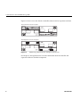
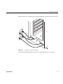
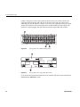
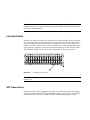
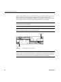
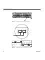
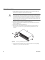
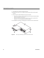
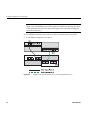
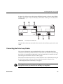
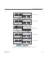
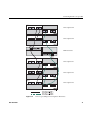
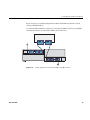
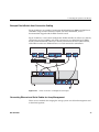
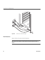
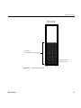
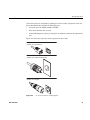
In Figure 5-2, callout 1 shows the location of ESM A (inverted), callout 2 shows ESM B.
Callout 3 shows ports 1A (In) and 1B (Out), while callout 4 shows ports 2A/2B (which
are reserved).
Figure 5-2
Drive Expansion ESM Ports
Note that drive enclosures connected to the same drive channel must operate at the same
speed.
Connecting the Drive Loop Cables
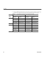
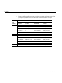
The system is designed to support redundant drive loops. A redundant drive loop
consists of one or more expansion enclosures connected to the controller enclosure using
data cables. In a redundant configuration, if one data path fails, the controller uses the
other data path to maintain access to the drive group.
Follow these instructions to cable two or more enclosures into a redundant drive loop. If
the drive loop contains only one enclosure, skip this procedure and proceed to
“Connecting the System to the Host(s)” on page 74.
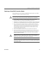
Warning: Electrostatic discharge can damage sensitive components. Use
appropriate antistatic precautions before handling any components.
007-4834-001
65