1
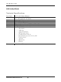
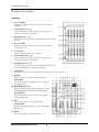
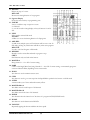
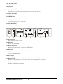
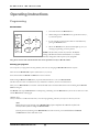
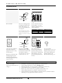
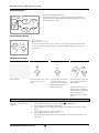
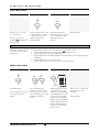
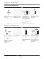
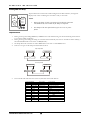
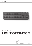
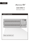
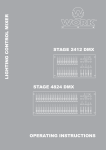
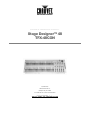
TECHNICAL REFERENCE & MANUAL
Stage Designer™ 48
TFX-48CON
CHAUVET
3000 North 29th Ct.
Hollywood, FL 33020
Tel: 954-929-1115 Fax: 954-929-5560
www.CHAUVETlighting.com
T A B L E
O F
C O N T E N T S
Table of Contents
BEFORE YOU BEGIN..........................................................................................................4
Unpacking Instructions ..................................................................................................................................................... 4
Powering ........................................................................................................................................................................... 4
Warnings........................................................................................................................................................................... 4
What is enclosed ............................................................................................................................................................... 4
INTRODUCTION ..................................................................................................................5
Technical Specifications ................................................................................................................................................... 5
Product Overview ............................................................................................................................................................. 6
Front View .................................................................................................................................................................. 6
Rear Panel................................................................................................................................................................... 8
OPERATING INSTRUCTIONS.............................................................................................9
Programming .................................................................................................................................................................... 9
Record Enable ............................................................................................................................................................ 9
Securing your programs.............................................................................................................................................. 9
Programming Scenes ................................................................................................................................................ 10
Editing............................................................................................................................................................................. 11
Edit Enable ............................................................................................................................................................... 11
Erase a Program........................................................................................................................................................ 11
Erase All Programs................................................................................................................................................... 12
Clear a Scene or Scenes............................................................................................................................................ 12
Delete a Step or Steps............................................................................................................................................... 12
Insert a Step or Steps ................................................................................................................................................ 13
Modify a Step or Steps ............................................................................................................................................. 13
Running the Show........................................................................................................................................................... 14
Running Chase Programs ......................................................................................................................................... 14
Running a Program in Audio.................................................................................................................................... 14
Running a Program with the Speed Slider................................................................................................................ 15
Running a Program with the Standard Beat.............................................................................................................. 15
Change the Speed Mode between 5 Minutes and 10 Minutes ........................................................................................ 16
MIDI IN .......................................................................................................................................................................... 16
Setting MIDI IN ....................................................................................................................................................... 16
Setting MIDI OUT ................................................................................................................................................... 16
Exit MIDI Setting ..................................................................................................................................................... 16
Receiving MIDI File Dump...................................................................................................................................... 16
Sending MIDI File Dump......................................................................................................................................... 17
Implementation......................................................................................................................................................... 17
Brief Summary of Main Functions ................................................................................................................................. 18
Reverse the direction of the scene ............................................................................................................................ 18
Fade Time................................................................................................................................................................. 18
Tap Sync Button ....................................................................................................................................................... 18
Master Slider ............................................................................................................................................................ 18
Single Mode ............................................................................................................................................................. 18
Mix Mode ................................................................................................................................................................. 18
Dimmer Display ....................................................................................................................................................... 18
Blind and Home........................................................................................................................................................ 19
Park........................................................................................................................................................................... 19
Add and Kill ............................................................................................................................................................. 19
Double Preset ........................................................................................................................................................... 19
Issue Date:
Rev. No.
1
January 2004
Version
Date
Description
2.03
March 2004
TFX-48C Users Guide version 2.02: Revised: V.M. at CHAUVET
T A B L E
O F
C O N T E N T S
APPENDIX .........................................................................................................................20
Maintenance.................................................................................................................................................................... 20
DMX Primer ................................................................................................................................................................... 20
Returns Procedure........................................................................................................................................................... 20
Claims ............................................................................................................................................................................. 20
General Troubleshooting ................................................................................................................................................ 21
Issue Date:
Rev. No.
1
January 2004
Version
Date
Description
2.03
March 2004
TFX-48C Users Guide version 2.02: Revised: V.M. at CHAUVET
B E F O R E
Y O U
B E G I N
Before you Begin
Unpacking Instructions
Immediately upon receiving a fixture, carefully unpack the carton, check the contents to ensure that all parts are present,
and have been received in good condition. Notify the shipper immediately and retain packing material for inspection if
any parts appear damaged from shipping or the carton itself shows signs of mishandling. Save the carton and all packing
materials. In the event that a fixture must be returned to the factory, it is important that the fixture be returned in the
original factory box and packing.
Powering
To determine the power requirements for a particular fixture, see the label affixed to the back plate of the fixture or refer
to the fixture’s specifications chart. A fixture’s listed current rating is its average current draw under normal conditions.
All fixtures must be powered directly off a switched circuit and cannot be run off a rheostat (variable resistor) or dimmer
circuit, even if the rheostat or dimmer channel is used solely for a 0% to 100% switch. Before applying power to a
fixture, check that the source voltage matches the fixture’s requirement. All fixtures must be connected to circuits with a
suitable Earth Ground. Check the fixture or device carefully to make sure that if a voltage selection switch exists that it is
set to the correct line voltage you will use.
Warnings
1.
This product is intended for indoor use only!
2. Keep out of the reach of children!
3. Make sure power cord is never crimped or damaged.
4. Never disconnect power cord by pulling or tugging on the cord.
5. Always make sure that you are connecting to the proper voltage and that the line voltage you are
connecting to is not higher than that stated on decal or rear panel of the fixture.
6. Do not disassemble this electrical product; there are no user serviceable parts inside.
7. Always disconnect from power source before servicing or replacing fuse and be sure to replace with
same fuse type.
8. To prevent risk of fire or shock, do not expose fixture to rain or moisture.
What is enclosed
Manual / Warranty Card
TFX-48C Controller
Power Adapter
TFX-48C Users Manual Version 2.03
4
I N T R O D U C T I O N
Introduction
Technical Specifications
Power Input
Adaptor
DMX Out
MIDI
Fuse
Dimensions
Shipping
Features
Warranty
DC 12~18V 500mA Minimum
AC ~230V 50Hz, DC 12V 500mA
AC ~120V 60Hz, DC 12V 500mA
3 pin male XLR
In/Out/Thru – 5 pin interface
(internal) F.05A 250V 5x20mm
710mm x 266mm x 90mm / 27.95” x 10.47” x 3.54”
7.3Kg / 16Lbs
48 DMX Channel on faders
48 programs
4,200 steps
4 pages of 48 scenes
Mix and match chases
Override chases on the fly
Beat activation, tap sync, auto run, midi
Polarity selector
Auto run
Midi In/Out
Blackout
2 Year Limited Warranty
TFX-48C Users Manual Version 2.03
5
I N T R O D U C T I O N
Product Overview
Front View
1.
Preset A LEDs
Indicates the current intensity of the channel enumerated.
Channels 1 ~ 24.
2. Channel Sliders (1 ~ 24)
These 24 sliders are used to control and/or program the
intensities of channel 1 through 24.
3. Flash Buttons (1 ~ 24)
Flash buttons are used to bring an individual channel up to full
intensity.
4. Preset B LEDs
Indicates the current intensity of the channel enumerated.
Channels 25 ~ 48.
5. Scene LEDs
Turns on when relevant scenes are active.
6. Channel Sliders (25 ~ 48)
These 24 sliders are used to control and/or program the
intensities of channel 25 through 48.
7. Flash Buttons (25 ~ 48)
Flash buttons are used to bring an individual channel up to full
intensity. These are also used for programming.
8. Dark Button
This button is used to momentarily blackout overall output of the controller.
9. DOWN
Down functions to modify a scene in Edit mode.
BEAT REV
Is used to reverse the chasing direction of a program
with regular beat.
10. MODE SELECT (10)
Each tap will activate the operating mode in the order:
.CHNS/SCENES, Double Preset and Single Preset.
REC SPEED
This button sets the speed of any of the programs
chasing in Mix mode.
11. UP
Up is used to modify a scene in Edit mode.
CHASE REV
Reverses the chasing direction of a scene under Speed
Slider Control
12. PAGE
Tap to select pages of scenes from Page 1 ~ 4.
TFX-48C Users Manual Version 2.03
6
I N T R O D U C T I O N
13. DELETE
Deletes any step of a scene.
REV ONE
Reverses the chasing direction of any program.
14. Segment Display
Shows the current activity or programming state.
15. INSERT
Insert is to add one step or steps into a scene.
% OR 0-255
% or 0-255 is used to change display value cycle between % and 0255.
16. EDIT
Edit is used to activate Edit mode.
ALL REV
All Rev is to reverse the chasing direction of all programs.
17. ADD KILL
In Add mode, multiple scenes or Flash buttons will be on at a time. In
Kill mode, pressing any Flash button will kill any other scenes prgrams.
REC EXIT
Is used to exit from Program or Edit mode.
18. RECORD
Record is used to activate Record mode or program a step.
SHIFT
Shift functions only used with other buttons.
19. MASTER A
Brings channel 1 ~ 12 to full of current setting.
20. PARK
Used to select Single/Mix Chase, bring Channel 13 ~ 24 to full of current setting, or momentarily program a
scene into Master B slider, depending on the current mode.
21. HOLD
This button is used to maintain current scene.
22. STEP
This button is used to go to next step when the Speed Slider is pushed to the bottom or in Edit mode.
23. AUDIO
Activates audio sync of chase and audio intensity effects.
24. MASTER Slider A
This slider controls overall output of all channels.
25. MASTER Slider B
This slider controls the chase of all channels.
26. BLIND
This function takes the channel out of the chase of a program in CHNS/SCENE mode.
27. HOME
This button is used to deactivate the BLIND.
28. TAP SYNC
Repeatedly tapping this button establishes the chase speed.
TFX-48C Users Manual Version 2.03
7
I N T R O D U C T I O N
29. FULL ON
This function brings overall output to full intensity.
30. BLACK OUT
This button is used to kill all output with the exception of Flash and Full On.
31. FADE Time Slider
Used to adjust the fade time.
32. SPEED Slider
Used to adjust the chase speed.
33. AUDIO Level Slider
Controls the sensitivity of the audio input.
34. FOG MACHINE
Trigger external Fog Machine.
Rear Panel
DC INPUT
DMX OUT
MIDI
ON OFF
1= Ground
2= Data3= Data+
2
DC 12V 20V
500 m A min
35
THRU
36
OUT
AUDIO
1= Ground
2= Data+
3= Data-
1/4"stereo jack
100mV 1Vp-p
IN
37
FOG MACHINE
LINE IN
1
3
REMOTE
DMX polarity selec t
38
39
Full on
Stand By
or Black Out
40
41
GND
42
35. Power Switch
Turns power On or Off to device.
36. DC Input
DC 12~20V, 500mA Min.
37. Midi Thru/Out/In
MIDI ports for connection to a sequencer or MIDI device.
38. DMX Out
Method of connection to DMX-512 compatible devices.
39. DMX Polarity Select
Used to select DMX polarity.
40. Audio Input
This jack accepts a line level audio input signal ranged from 100mV to1V pp.
41. Remote Input
Blackout and Full On may be controlled by a remote control using standard ¼” stereo jack.
42. FOG Machine Connector
Provides power feed for Fog machines.
TFX-48C Users Manual Version 2.03
8
O P E R A T I N G
I N S T R U C T I O N S
Operating Instructions
Programming
Record Enable
1
1.
Press and hold down the Record button.
2.
While holding down the Record button, tap the Flash buttons, 1,
6, 6 and 8 in sequence.
3.
If your controller is currently in the blackout mode disable it by
pressing the blackout button
4.
Release the Record button, the Record LED lights up, now you
can begin programming your chase patterns.
6
RECORD
8
6
Press &
Hold
Button
NOTE! The first time you turn on your unit, the default
setting of the Record Code is Flash buttons 1, 6, 6 and 8.
You may change this code to protect your programs.
Also, please note that this manual will refer often to this procedure exactly as “Record enable”.
Securing your programs
You can protect your programs from being edited by other users by changing the Record Code number sequence.
Enter the current Record Code sequence (Flash buttons 1, 6, 6 and 8).
Press and hold down the Record and Edit buttons at the same time.
While holding the Record and Edit button, tap the desired Flash button to enter a new Record Code.
The Record Code consists of 4 Flash buttons (any combination of buttons). It must use 4 Flash buttons.
Enter your new Record Code a second time. All channel LEDs and scene LEDs will flash three times indicating that the Record
Code has changed.
Exit Record mode. Tap the Rec Exit button while pressing and holding down the Record button, release the two buttons at a time
until the Record mode is disengaged.
IMPORTANT!
Always remember to exit Record mode when you are done programming, otherwise you may lose control of your unit.
Note:
During the process of entering a new Record Code, if upon completion the LEDs do not flash, this
means you have failed to change the Record Code.
If in the process of entering a new Record Code you wish to cancel, press and hold down the Record
and Exit buttons at the same time to exit.
TFX-48C Users Manual Version 2.03
9
O P E R A T I N G
I N S T R U C T I O N S
Programming Scenes
1 .
2 .
3 .
MODE
SELECT
CHASE
A
SCENES
DOUBLE
1-48 SINGLE
Record Enable.
1
PRESET
B
3
5
4
10
10
10
10
10
8
8
8
8
8
6
6
6
6
6
4
4
4
4
4
2
2
2
2
2
0
0
0
0
0
PRESET
Select the 1-48 Single mode
by tapping the Mode Select
button. This will give you
control of all 48 channels as
you program.
Be sure that Master faders A & B are
both set at maximum. (Master A is at its
maximum in the Up position, while
Master B is at its maximum in the Down
position.)
4 .
2
5 .
Create a desired scene using
Channel Sliders 1-48. The
following table illustrates the
output comparison.
Slider Position
0
5
10
Output as %
0
50%
100%
6 .
DMX Output Value
0
128
255
7 .
MODE
SELECT
CHASE
A
Repeat step 3 and step 4 until
all desired steps have been
programmed into memory.
You may program up to 1000
steps into memory
28
29
3
4
5
RECORD
RECORD
Once the scene is satisfactory,
tap the Record button to
program the scene as a step
into the memory.
27
SCENES
DOUBLE
PRESET
1-48 SINGLE
PRESET
B
10
10
10
10
8
8
8
8
6
6
6
6
4
4
4
4
2
2
2
2
0
0
0
0
REC
EXIT
FLASH 25-48
Select the CHASE
SCENES mode by tapping
the Mode Select button. This
will enable the ability to
record a chase or a scene to
a Flash buttons 25 ~ 48.
Press a Flash button
between 25 and 48 (Preset
B) while holding down the
Record button. All LED will
flash indicating the scenes
have been programmed into
memory.
You can continue
programming or exit. To exit
Program mode, tap the Exit
button while holding down
the Record button, the
Record LED should go out.
Example:
Program a 16 steps chase with
channel 1-32 at full in
sequence into Flash button 25
of Page 1.
1.
2.
3.
4.
5.
6.
7.
8.
Record enable.
Push Master A up, B down and Fade slider up to starter positions.
Tap the Mode Select button to select 1-48 Single mode.
Push Channel slider 1 to the top position, its LED light at full intensity.
Tap the Record button to program this step into memory.
Repeat steps 4 and 5 until you’ve programmed Channel sliders 1-32.
Tap the Mode Select button to change to Chase/Scenes mode..
Tap the Flash button 25 while holding down the Record button, all LEDs will flash
indicating you’ve programmed the chase into memory.
TFX-48C Users Manual Version 2.03
10
O P E R A T I N G
I N S T R U C T I O N S
Editing
Edit Enable
1 .
2 .
3 .
4 .
MODE
SELECT
1
2
3
4
EDIT
PAGE
CHAS
E
A
Record Enable.
Use the Page button to
select the page the program
you wish to edit is on.
5 .
6
27
28
29
3
4
5
SCENES
DOUBLE
PRESET
1-48 SINGLE
PRESET
B
Tap the Mode Select button
to select CHASE
SCENES.
Press and hold down the
Edit button.
3 .
4 .
EDIT
EDIT
10
10
10
10
8
8
8
8
6
6
6
6
4
4
4
4
2
2
2
2
0
0
0
0
FLASH 25-48
While holding down the Edit
button, tap the Flash button
that corresponds to program
you wish to edit.
Release the Edit button, the
relevant scene LED should
light indicating you are in the
Edit mode.
Erase a Program
1 .
2 .
1
2
3
27
28
29
3
4
5
EDIT
4
PAGE
10
10
8
8
6
6
4
4
2
2
0
0
Tap this
button
twice!
10
10
8
8
6
6
4
4
2
2
0
0
FLASH 25-48
Record Enable.
Use the Page button to
select the page the program
you wish to erase is on.
TFX-48C Users Manual Version 2.03
11
While holding down the Edit
button, tap the Flash button
(25-48) twice.
Release the two buttons, all
LEDs flash, indicating the
program is erased.
O P E R A T I N G
I N S T R U C T I O N S
Erase All Programs
Press
& Hold
Button
1
4
3
2
1.
2.
RECORD
Press and hold the Record button.
Tap the Flash buttons 1, 4, 2 and 3 in sequence while holding the
Record button. All LEDs will flash, indicating all programs stored in
memory have been erased.
Clear a Scene or Scenes
RECORD
1.
2.
3.
Record enable.
Record a scene or scenes.
If you not satisfied with the scene or scenes, you may tap the Rec Clear button while
pressing and holding the Record button, all LEDs will flash, indicating the scenes have
been cleared.
REC
EXIT
Delete a Step or Steps
1 .
2 .
3 .
STEP
4 .
DELETE
RECORD
REC
EXIT
Record Enable.
Tap the Step button to scroll
to the step you wish to
delete.
Tap the Delete button when
you reach to the step you
wish to delete, all LEDs will
flash briefly indicating the
deletion of the step.
Continue steps 2 and 3 until
all the unwanted steps have
been deleted.
Tap the Rec Exit button
while pressing and holding
down the Record button, the
Scene LED goes out,
indicating the exit of Edit
mode.
Example:
Delete the third step of the
program on Flash button 25
on Page 2.
1.
2.
3.
4.
5.
6.
7.
Record enable.
Tap the Mode Select button to select CHASE
SCENE mode.
Tap the Page button until Page 2 LED lights.
Tap the Flash button 25 while pressing and down the Edit button, the Scene LED
lights.
Tap the Step button to scroll to the third step.
Tap the Delete button to delete the step.
Tap the Rec Exit button while pressing and holding down the Record button to exit
Edit mode.
TFX-48C Users Manual Version 2.03
12
O P E R A T I N G
I N S T R U C T I O N S
Insert a Step or Steps
1 .
2 .
3 .
4 .
STEP
Record a scene or scenes
you wish to insert.
Be sure you’re in and
SCENE Enter
CHASE
the Edit mode.
INSERT
Tap the Step button to scroll
to the step which you wish
to insert before. You may
read the step from the
Segment Display.
Tap the Insert button to
insert the step you’ve created
before, all LEDs will flash,
indicating the step is
inserted.
Exit Edit mode.
Example:
EXAMPLE: Insert a step with
channels 1-12 fully on at a
time between step 4 and 5 of
program 35.
1.
2.
3.
4.
5.
6.
7.
Record enable.
Push Channel sliders 1-12 to the top and record the scene as a step.
SCENE mode.
Tap the Mode Select button to select CHNS
Tap the Page button until Page 2 LED lights.
Tap the Flash button 35 while holding down the Edit button, the corresponding scene
LED lights.
Tap the Step button to scroll to the step 4.
Tap the Insert button to insert the scene you’ve created before.
Modify a Step or Steps
1 .
2 .
3 .
4 .
UP
STEP
DOWN
27
28
29
3
4
5
UP
10
10
10
10
8
8
8
8
6
6
6
6
4
4
4
4
2
2
2
2
0
0
0
0
FLASH 25-48
Enter Edit mode.
Tap the Step button to scroll
to the step you wish to
modify.
Press and hold the Up
button if you want to raise
the intensity. If you want to
lower the intensity, press and
hold down the Down
button.
TFX-48C Users Manual Version 2.03
13
While holding down the Up
or Down button, tap the
Flash button corresponding
to the DMX channel of the
scene you wish to modify
until you reach the desired
intensity value read from the
Segment Display. Then you
may tap the Flash buttons
until you are satisfied with
the new scene.
Repeat steps 1, 2 and 3 until
all the steps have been
modified.
Exit Edit mode.
O P E R A T I N G
I N S T R U C T I O N S
Running the Show
Running Chase Programs
1 .
2 .
3 .
4 .
MASTER
DOWN
STEP
UP
10
0
8
2
6
4
6
4
2
8
0
10
A
Tap the Page button to
select the correct page the
program you wish to run is
located.
10
8
8
6
6
4
4
2
2
0
0
B
BLIND
Tap the Mode Select button
to select CHASE
SCENES mode indicated by
the red LED.
10
HOME
Push Master Slider A all the
way up and B to its
maximum position (fully
down).
Move the desired Channel
slider (25-48) to its
maximum position to trigger
the program, and the
program will fade in
depending upon current fade
time.
3 .
4 .
5 .
10
10
8
8
6
6
4
4
2
2
0
0
Move the Channel slider to
adjust the output of the
current program.
Running a Program in Audio
1 .
2 .
AUDIO LEVEL
AUDIO
Use built-in microphone or
plug the audio source into
the RCA Audio jack.
Tap the Audio button until
its LED lights, indicating
Audio mode is active.
Select your program as
described above.
.
TFX-48C Users Manual Version 2.03
14
10
10
8
8
6
6
4
4
2
2
0
0
Use the Audio level slider to
adjust the music sensitivity.
AUDIO
To return to normal mode,
tap the Audio button a
second time causing its
LED goes out, the Audio
mode is disengaged.
O P E R A T I N G
I N S T R U C T I O N S
Running a Program with the Speed Slider
1 .
2 .
3 .
4 .
27
28
29
3
4
5
5MIN
10MIN
SPEED
.ISEC
AUDIO
REC SPEED
10
10
10
10
8
8
8
8
6
6
6
6
4
4
4
4
2
2
2
2
0
0
0
.ISEC
.2s
.2s
.5s
1s
2s
5s
1s
2s
5s
10s
10s
20s
30s
1m
1m
2m
2m
5m
10m
MINS
SHOW
MODE
5m
MINS
SHOW
MODE
0
FLASH 25-48
Be sure the Audio mode is
disengaged, that is the Audio
LED goes out.
Select your program as
described in section 2.3.1
“Running chase programs”
Move the Speed slider to the
SHOW MODE position
(the bottom), then tap the
Flash button (25-48) while
pressing and holding down
the Rec Speed button, the
corresponding program will
not run with the Standard
beat any longer.
Now you may move the
Speed Slider to select your
desired speed.
NOTE: The step 3 is not necessary if the selected program is not recorded with Standard Beat.
Running a Program with the Standard Beat
1 .
2 .
3 .
4 .
5MIN
10MIN
SPEED
AUDIO
.ISEC
SINGLE CHASE
MIX CHASE
PARK
Select your program as
described above.
.2s
.2s
1s
2s
5s
10s
TFX-48C Users Manual Version 2.03
29
4
5
REC SPEED
10
10
10
10
8
8
8
8
6
6
6
6
4
4
4
4
10s
20s
30s
1m
2
2
2
2
2m
5m
10m
MINS
SHOW
MODE
0
0
0
0
Move the Speed slider until
Segment Display reads your
desired value.
You may tap the Tap Sync
button twice to define your
beat time.
Tap the Park button to select
Mix Chase mode, the LED
lights indicating this
selection.
28
3
.ISEC
.5s
1s
2s
5s
1m
2m
5m
MINS
SHOW
MODE
Be sure the Audio mode is
disengaged. Tap the Mode
Select button to select
SCENE mode.
CHASE
27
FLASH 25-48
While pressing and holding
down the Rec Speed button,
tap the Flash button(25-48)
that stores the program.
The program will then run
with the set time or beat
when engaged.
Repeat steps 4 and 5 to set a
new beat time.
15
O P E R A T I N G
I N S T R U C T I O N S
Change the Speed Mode between 5 Minutes and 10 Minutes
1 .
2 .
RECORD
3 .
27
28
29
3
4
5
RECORD
10
10
8
8
6
6
4
4
2
0
Tap this
button
three
times!
10
10
8
8
6
6
4
4
2
2
2
0
0
0
FLASH 5 or 10
Press and hold the Record
button.
Tap the Flash button 5 or 10
three times while holding
down the Record button.
The 5 MIN or 10 MIN
should light up indicating the
Speed slider is set to run in
the 5 or 10 minute mode..
MIDI IN
Setting MIDI IN
Setting MIDI OUT
1 .
2 .
1 .
27
28
29
10
10
27
28
29
3
4
5
8
8
3
4
5
6
6
RECORD
10
10
8
8
6
6
4
4
2
2
0
0
Tap this
button
three
times!
RECORD
10
10
4
4
10
10
8
8
2
2
8
8
6
6
0
0
6
6
4
4
4
4
2
2
2
2
0
0
0
0
FLASH BUTTONS
1-16
FLASH 1
Tap this
button
three
times!
10
10
8
8
6
6
4
4
2
2
0
0
10
10
8
8
6
6
4
4
2
2
0
0
FLASH BUTTONS
1-16
FLASH 2
Tap the Flash button 1 three
times while holding down the
Record button, the Segment
Display reads “CHI” indicating
MIDI IN channel setup is
available.
Tap the Flash button
numbered from 1-16 to
assign MIDI IN Channel 116, the relevant channel
LED lights indicating
MIDI IN channel is set.
Exit MIDI Setting
RECORD
REC
EXIT
2 .
Tap the Flash button 2 three
times while holding down
the Record button, the
Segment Display reads
“CHO” indicating MIDI IN
channel setup is available.
Tap the Flash button
numbered from 1-16 to
assign MIDI OUT Channel
1-16, the relevant channel
LED lights indicating
MIDI OUT channel is set.
Receiving MIDI File Dump
Press and hold down the
Record button. While holding
down the Record button, tap
the Rec Exit button to exit
MIDI setting.
27
3
RECORD
FLASH 3
TFX-48C Users Manual Version 2.03
16
10
10
8
8
6
6
4
4
2
0
28
29
4
5
Tap this
button
three
times!
10
10
8
8
6
6
4
4
2
2
2
0
0
0
Tap the Flash button 3 three
time while holding down the
Record button, the Segment
Display reads “IN”
indicating the controller is
ready to receive MIDI file
dump.
O P E R A T I N G
I N S T R U C T I O N S
Sending MIDI File Dump
27
28
29
3
4
5
RECORD
10
10
8
8
6
6
4
4
2
2
0
0
Tap the Flash button 4 three time while holding down the Record button, the Segment
Display reads “OUT” indicating the controller is ready to send a file.
Tap this
button
three
times!
10
10
8
8
6
6
4
4
2
2
0
0
NOTE:
FLASH 4
1.
During file dump, all other operations will not function. Functions
will automatically return when the file dump is completed.
2.
File dump will be interrupted and stop if errors occur or power
failure.
Implementation
1.
2.
3.
4.
During receiving and sending MIDI data, all MIDI scenes and channels being run will automatically paused if there
is no response within 10 minutes.
During receiving and sending file dump, the controller will automatically search for or send Device ID of 55h(85), a
file named DC2448 with an extension of “BIN(SPACE)”.
File dump allows this controller to send its MIDI data to next unit or other MIDI devices.
Three are two types of file dump mode described as below.
Open Loop Mode
CONTROLLER
MIDI OUT
RECEIVER
MIDI IN
MIDI OUT
MIDI IN
Close Loop Mode
CONTROLLER
MIDI OUT
5.
MIDI IN
RECEIVER
MIDI OUT
MIDI IN
The controller will send and receive Note On/Off data via the Flash buttons.
NOTE NUMBER
Decimal
Hex
22-69
[16H-45H]
22-117
[16H-45H]
118
[76H]
119
[77H]
120
[78H]
121
[79H]
122
[7AH]
123
124
125
126
VELOCITY
FUNCTION
Program Master
Channel Light
Turn on or off program 1-48
activate Channel 1-48
FULL-ON
DARK
HOLD
Turn on or off AUDIO
CHNS
SCENES
DOUBLE PRESET Mode
SINGLE PRESET Mode
Step
BLACK OUT
[7BH]
[7CH]
[7DH]
[7EH]
TFX-48C Users Manual Version 2.03
17
O P E R A T I N G
I N S T R U C T I O N S
Brief Summary of Main Functions
Reverse the direction of the scene
1.
2.
3.
4.
Reverse the direction of all the scenes. Press the ALL REV Button, all the scenes should change their directions.
Reverse the chasing direction of all the programs with speed control: Press the Chase Rev Button.
Reverse the chasing direction of all the programs with standard beat: Press the Beat Rev Button.
Reverse chasing direction of any program: Press and hold down the Rec One Button, then press down the Flash
Button corresponding to your desired program and release together.
Fade Time
1.
2.
The amount of time it will take for the dimmer to go from zero output to maximum output, and vice verse.
Fade time is adjusted through the Fade Time Slider, which varies from instant to 10 mimutes.
Tap Sync Button
1.
2.
3.
The Tap Sync button is used to set and synchronize the chase rate (the rate at which all scenes will sequence) by
tapping the button several times. The chase rate will synchronize to the time of the last two taps. The LED above
the Step Button will flash at the new chase rate. The chase rate may be set anytime whether or not a program is
running.
Tap Sync will override any previous setting of the speed slider control until the slider is moved again.
Use of Tap Sync in setting a standard beat is the same with speed control slider.
Master Slider
Master Slider control provides proportion level control over all channels and scenes with the exception of the Flash
Buttons. For example: Whenever the Master slider control is at minimum all stage outputs will be at zero except for any
resulting from a Flash Button or FULL ON Button. If the Master is at 50%, all outputs will be at only 50% of the setting of
current channel or scenes except for any resulting from a Flash Button or FULL ON Button. If the Master is at full all
outputs will follow the unit setting. Master A always controls outputs of channels. Master B controls program or a scene
except in Double Press Mode.
Single Mode
1.
2.
3.
4.
5.
All programs will run in sequential order starting in the order of program number.
The Segment Display will read the running program number.
All programs will be controlled by the same Speed Slider.
Press the MODE SELECT BUTTON and select “CHNS
SCENES”.
Press the PARK BUTTON to select SINGLE CHASE MODE. A red LED will indicate this selection.
Mix Mode
1.
2.
3.
4.
Will run all programs synchronously.
All programs can be controlled by the same SLIDER SPEED, or each programs speed may be controlled
individually. (See Speed Setting).
SCENES”.
Press the MODE SELECT BUTTON and select “CHNS
Press the PARK BUTTON to select MIX CHASE MODE. A yellow LED will indicate this selection.
Dimmer Display
1.
2.
The 3-Digit Segment Display is used to display intensity percentage or absolute DMX value.
To change between percentage and absolute value: Press and hold the Shift Button. While holding down the Shift
button, press the 5 or 0-255 Button to switch between percentage and absolute values.
TFX-48C Users Manual Version 2.03
18
O P E R A T I N G
3.
I N S T R U C T I O N S
If the Segment Display reads, for example, “076”, it means a percentage value 76%. If the Segment Display reads
“076”, it means the DMX value 76.
Blind and Home
1.
2.
3.
Blind function takes channels temporally out from a chase, when the chase is running, and gives you manual control
over the channel.
Press and hold the Blind Button and tap the relative Flash Button you want to temporarily take out of the chase.
To return to normal chase again press and hold the Home Button and push the Flash Button you want to return to
normal chase.
Park
1.
2.
3.
In CHASE O P SCENES Mode, press down the button you can change the chasing mode of programs between
Single Mode and Mix Mode.
In Double Preset Mode, pressing down this button is equal to pushing Master slider B to the top.
In Single Preset Mode, this button could temporarily record current output, with Master Slider B to adjust.
Add and Kill
1.
2.
3.
The ADD/KILL Button changes the mode of the flash buttons. Normally the flash buttons are in Add mode,
whereas pressing any flash button will not kill other scenes, allowing multiple scenes to be on at a time.
The Kill mode is activated by pressing the Add/Kill button and illuminating the LED above it. Pressing any flash
button will kill other active SCENE or Program.
In Kill mode, the killed program does not stop running but can not output.
Double Preset
1.
2.
3.
4.
Press Mode Select Button to enter A Double Preset Mode.
In this mode, Channel Sliders 1-24 and channel sliders 25-48 both control Channel 1-24.
Master A controls channel Slider 1-24 while Master B controls Channel Sliders 25-48.
In this Mode, no scene can be recorded.
Example
1.
2.
3.
Enter the Double Preset Mode
Push Channel Sliders 1 to 6 to the top and move Channel Sliders 19-24 to the maximum.
Move Master A and B to the same level and push them to the same direction, you will get a scene.
TFX-48C Users Manual Version 2.03
19
A P P E N D I X
Appendix
Maintenance
To maintain optimum performance and minimize wear, device should be cleaned frequently. Usage and environment
are contributing factors in determining frequency. As a general rule, device should be cleaned at least twice a month.
Dust build up can cause overheating. This can lead to increased mechanical wear. Be sure to power off device before
conducting maintenance.
Unplug device from power. Use a vacuum or air compressor and a soft brush to remove dust collected on external vents
and internal components.
DMX Primer
There are 512 channels in a DMX-512 connection. Channels may be assigned in any manner. A fixture capable of
receiving DMX 512 will require one or a number of sequential channels. The user must assign a starting address on the
fixture that indicates the first channel reserved in the controller. There are many different types of DMX controllable
fixtures and they all may vary in the total number of channels required. Choosing a start address should be planned in
advance. Channels should never overlap. If they do, this will result in erratic operation of the fixtures whose starting
address is set incorrectly. You can however, control multiple fixtures of the same type using the same starting address as
long as the intended result is that of unison movement or operation. In other words, the fixtures will be slaved together
and all respond exactly the same.
DMX fixtures are designed to receive data through a serial Daisy Chain. A Daisy Chain connection is where the DATA OUT of one
fixture connects to the DATA IN of the next fixture. The order in which the fixtures are connected is not important and has no
effect on how a controller communicates to each fixture. Use an order that provides for the easiest and most direct cabling. Connect
fixtures using shielded two conductor twisted pair cable with three pin XLR male to female connectors. The shield connection is pin
1, while pin 2 is Data Negative (S-) and pin 3 is Data positive (S+). CHAUVET carries 3-pin XLR DMX compliant cables, DMX-10
(33’), DMX-4.5 (15’) and DMX-1.5 (5’)
Returns Procedure
Returned merchandise must be sent prepaid and in the original packing, call tags will not be issued. Package must be
clearly labeled with a Return Merchandise Authorization Number (RA #). Products returned without an RA # will be
refused. Call CHAUVET and request RA # prior to shipping the fixture. Be prepared to provide the model number,
serial number and a brief description of the cause for the return. Be sure to properly pack fixture, any shipping damage
resulting from inadequate packaging is the customer’s responsibility. CHAUVET reserves the right to use its own
discretion to repair or replace product(s). As a suggestion, proper UPS packing or double-boxing is always a safe method
to use.
Claims
Damage incurred in shipping is the responsibility of the shipper; therefore the damage must be reported to the carrier
upon receipt of merchandise. It is the customer's responsibility to notify and submit claims with the shipper in the event
that a fixture is damaged due to shipping. Any other claim for items such as missing component/part, damage not
related to shipping, and concealed damage, must be made within seven (7) days of receiving merchandise.
TFX-48C Users Manual Version 2.03
20
A P P E N D I X
General Troubleshooting
Applies to
Symptom
Solution(s)
Auto shut off
Check fan thermal switch reset
Beam is very dim or not bright
Clean optical system or replace lamp
Check 220/110v switch for proper setting
Lights
Breaker/Fuse keeps blowing
Check total load placed on device
Chase is too slow
Check users manual for speed adjustment
Device has no power
Check for power on Mains.
Check device’s fuse. (internal and/or external)
Fixture is not responding
Check DMX Dip switch settings for correct
addressing
Check DMX cables
Check polarity switch settings
Fixture is on but there is no
movement to the audio
Make sure you have the correct audio mode on the
control switches. If audio provided via ¼” jack, make
sure a live audio signal exists
Adjust sound sensitivity knob
Fluid indicator not working
The filter tip on the end of the tube inserted into the
fluid container must float freely in order to measure
correctly, check to see if perhaps it is stuck
Fogger or Snow output has
dropped
Clean with distilled water and vinegar
Replace hose
Lamps cuts off sporadically
Possible bad lamp or fixture is overheating.
Lamp may be at end of its life.
Light will not come on after
power failure
Some discharge lamps require a cooling off period
before the electronics in the fixture can kick start it
again, wait 5 to 10 minutes before powering up
Loss of signal
Use only DMX cables
Install terminator
Motor movements are jerky or
jumpy
Possible bad motor driver or sensors
Check polarity switch on controller
Moves slow
Check 220/110v switch for proper setting
No flash
Re-install bulb, may have shifted in shipping
No fog
Check fluid tank if empty
Make sure green light is on (for power)
No laser output
Bounce mirror motor may have shifted during
shipping, readjust
No light output
Check slip ring & brushes for contact
Install bulb
Call service technician
Relay will not work
Check reset switch
Check cable connections
Remote does not work
Make sure connector is firmly connected to device
Stand alone mode
All Chauvet lighting fixtures featuring stand-alone
functions do not require additional settings, simply
power the fixture and it will automatically enter into
this mode
Unit wobbles when rotating
Check for damages possibly incurred during
shipping
TFX-48C Users Manual Version 2.03
21
Foggers
& Snow
Controllers
Dimmers
& Chaser