1
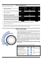
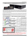
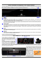
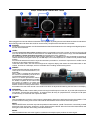
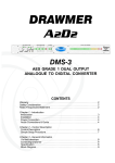
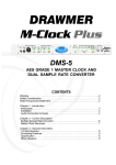
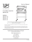
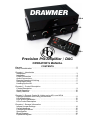
DRAWMER
HQ-b
HQ
HQ-r
Precision Pre-Amplifier / DAC
OPERATOR’S MANUAL
CONTENTS
Warranty . . . . . . . . . . . . . . . . . . . . . . . . . . . . . . . . . . . . . . . . . . . . . . . . . . . . . . . . . . . 2
Safety Consideration . . . . . . . . . . . . . . . . . . . . . . . . . . . . . . . . . . . . . . . . . . . . . . . . 2
Chapter 1 - Introduction
Introduction . . . . . . . . . . . . . . . . . . . . . . . . . . . . . . . . . . . . . . . . . . . . . . . . . . . . . . . 3
Installation . . . . . . . . . . . . . . . . . . . . . . . . . . . . . . . . . . . . . . . . . . . . . . . . . . . . . . . . 4
Power Connection . . . . . . . . . . . . . . . . . . . . . . . . . . . . . . . . . . . . . . . . . . . . . . . . . 4
Audio Connections . . . . . . . . . . . . . . . . . . . . . . . . . . . . . . . . . . . . . . . . . . . . . . . . . 5
Remote Operation & Linking . . . . . . . . . . . . . . . . . . . . . . . . . . . . . . . . . . . . . . . . . 7
Setup Input Levels . . . . . . . . . . . . . . . . . . . . . . . . . . . . . . . . . . . . . . . . . . . . . . . . . . 7
Hooking Up the HQ . . . . . . . . . . . . . . . . . . . . . . . . . . . . . . . . . . . . . . . . . . . . . . . . . 8
Chapter 2 - Control Description
Control Description . . . . . . . . . . . . . . . . . . . . . . . . . . . . . . . . . . . . . . . . . . . . . . . . . 9
Quick Operation . . . . . . . . . . . . . . . . . . . . . . . . . . . . . . . . . . . . . . . . . . . . . . . . . . 10
. . . . . . . . . . . . . . . . . . . . . . . . . . . . . . . . . . . . . . . . . . . . . . . . 10
Safety Features
Chapter 3 - Remote Control & Linking using HQ-r and HQ-b
Remote Operation and Linking for Surround . . . . . . . . . . . . . . . . . . . . . . . . . . . 11
HQ-b Description . . . . . . . . . . . . . . . . . . . . . . . . . . . . . . . . . . . . . . . . . . . . . . . . . 12
HQ-r & HQ-b Installation . . . . . . . . . . . . . . . . . . . . . . . . . . . . . . . . . . . . . . . . . . . 12
HQ-r Control Description. . . . . . . . . . . . . . . . . . . . . . . . . . . . . . . . . . . . . . . . . . . 13
Chapter 4 - General Information
Internal Jumper Settings . . . . . . . . . . . . . . . . . . . . . . . . . . . . . . . . . . . . . . . . . . . 14
If a fault develops . . . . . . . . . . . . . . . . . . . . . . . . . . . . . . . . . . . . . . . . . . . . . . . . . 15
Contacting Drawmer. . . . . . . . . . . . . . . . . . . . . . . . . . . . . . . . . . . . . . . . . . . . . . . .15
Specification . . . . . . . . . . . . . . . . . . . . . . . . . . . . . . . . . . . . . . . . . . . . . . . . . . . . .15
Block Diagram . . . . . . . . . . . . . . . . . . . . . . . . . . . . . . . . . . . . . . . . . . . . . . . . . . .16
Exploded Diagram . . . . . . . . . . . . . . . . . . . . . . . . . . . . . . . . . . . . . . . . . . . . . . . .17
COPYRIGHT
This manual is copyrighted © 2011 by Drawmer Electronics Ltd. With all rights reserved. Under copyright
laws, no part of this publication may be reproduced, transmitted, stored in a retrieval system or translated
into any language in any form by any means, mechanical, optical, electronic, recording, or otherwise, without the written permission of Drawmer Electronics Ltd.
ONE YEAR LIMITED WARRANTY
Drawmer Electronics Ltd., warrants the Drawmer HQ
Precision Pre-Amplifier / DAC to conform substantially to
the specifications of this manual for a period of one year
from the original date of purchase when used in accordance
with the specifications detailed in this manual. In the case
of a valid warranty claim, your sole and exclusive remedy
and Drawmer’s entire liability under any theory of liability
will be to, at Drawmer’s discretion, repair or replace the
product without charge, or, if not possible, to refund the
purchase price to you. This warranty is not transferable. It
applies only to the original purchaser of the product.
For warranty service please call your local Drawmer dealer.
Alternatively call Drawmer Electronics Ltd. at +44 (0)1709
527574. Then ship the defective product, with transportation
and insurance charges prepaid, to Drawmer Electronics
Ltd., Coleman Street, Parkgate, Rotherham, S62 6EL UK.
Write the RA number in large letters in a prominent position
on the shipping box. Enclose your name, address,
telephone number, copy of the original sales invoice and a
detailed description of the problem. Drawmer will not accept
responsibility for loss or damage during transit.
DRAWMER
HQ
Precision Pre-Amplifier / DAC
SAFETY CONSIDERATIONS
CAUTION - MAINS FUSE
TO REDUCE THE RISK OF FIRE
REPLACE THE MAINS FUSE ONLY WITH
A FUSE THAT CONFORMS TO IEC127-2.
250 VOLT WORKING, TIME DELAY TYPE
AND BODY SIZE OF 20mm x 5mm.
THE MAINS INPUT FUSE MUST BE
RATED AT 230V=T1A and 115V=T500mA.
This warranty is void if the product has been damaged by
misuse, modification or unauthorised repair.
THIS WARRANTY IS IN LIEU OF ALL WARRANTIES,
WHETHER ORAL OR WRITTEN, EXPRESSED, IMPLIED
OR STATUTORY. DRAWMER MAKES NO OTHER
WARRANTY EITHER EXPRESS OR IMPLIED,
INCLUDING, WITHOUT LIMITATION, ANY IMPLIED
WARRANTIES OF MERCHANTABILITY, FITNESS FOR
A PARTICULAR PURPOSE, OR NON-INFRINGEMENT.
PURCHASER’S SOLE AND EXCLUSIVE REMEDY
UNDER THIS WARRANTY SHALL BE REPAIR OR
REPLACEMENT AS SPECIFIED HEREIN.
IN NO EVENT WILL DRAWMER ELECTRONICS LTD. BE
LIABLE FOR ANY DIRECT, INDIRECT, SPECIAL,
INCIDENTAL OR CONSEQUENTIAL DAMAGES
RESULTING FROM ANY DEFECT IN THE PRODUCT,
INCLUDING LOST PROFITS, DAMAGE TO PROPERTY,
AND, TO THE EXTENT PERMITTED BY LAW, DAMAGE
FOR PERSONAL INJURY, EVEN IF DRAWMER HAS
BEEN ADVISED OF THE POSSIBILITY OF SUCH
DAMAGES.
CAUTION - MAINS CABLE
DO NOT ATTEMPT TO CHANGE
OR TAMPER WITH THE
SUPPLIED MAINS CABLE.
CAUTION - SERVICING
DO NOT PERFORM ANY SERVICING.
REFER ALL SERVICING TO QUALIFIED
SERVICE PERSONNEL.
WARNING
TO REDUCE THE RISK OF FIRE OR
ELECTRIC SHOCK DO NOT EXPOSE
THIS EQUIPMENT TO RAIN OR MOISTURE.
Some states and specific countries do not allow the
exclusion of implied warranties or limitations on how long
an implied warranty may last, so the above limitations may
not apply to you. This warranty gives you specific legal
rights. You may have additional rights that vary from state
to state, and country to country.
In the interests of product development, Drawmer reserve the right to modify or
improve specifications of this product at any time, without prior notice.
2
DRAWMER HQ OPERATOR’S MANUAL
CHAPTER 1
DRAWMER
PRECISION PRE-AMPLIFIER / DAC
Are you hearing what we’re hearing ?
How good is your Monitor Preamp ?
The monitor preamp is possibly the most important piece of equipment for both audio professionals and Hi-Fi enthusiasts
alike. It is the last piece of equipment before the speakers, so it requires zero coloration, precise balance, low noise,
wide bandwidth and a wide variety of input sources.
Top of the range designs use relay attenuators with high accuracy resistors to achieve the best balance between
channels. Unfortunately, as the volume is changed, the relays can be heard chattering. This can be irritating and also
reduces the life of the relays. Drawmer have found an innovative solution to this problem, giving the feel and smoothness
of a potentiometer, but with the accuracy of relay attenuation.
<>
Precision relay volume control. Accurate channel balance to 0.05dB
<>
Innovative (SilentRelay) volume management. (>100dB attenuation)
<>
State of the art DAC (-100dB THD & Noise and -114dB DnR)
<>
Ultra low crosstalk (> 100dB @ 20Hz to 20kHz)
<>
4 analog and 5 digital sources, with individual gain setting
<>
Intelligent source select allows A-B comparisons.
<>
Digital inputs to 192kHz 24bit with jitter reduction.
<>
RIAA input for accurate replay of vinyl
<>
Remote operation and linking for multi-channel systems
<>
Dual Headphone outputs
<>
Normal output levels up to +17dBu balanced
<>
Hot output levels up to +27dBu balanced
<>
Independent selection of Balanced and Unbalanced outputs for A/B speaker comparisons
<>
Internal Linear power supply with multi-stage regulation
<>
Additonal Dim, Mute and Mono controls, as well as preset volume levels, and a display
accurate to 0.5dB steps, via the HQ-r remote.
The Drawmer HQ sets a new standard in monitor Preamps, by combining a state of the art DAC with superior analog
design and an ingenious control system.
So what you hear is what you get - precisely.
DRAWMER HQ OPERATOR’S MANUAL
3
INSTALLATION
When you unpack your HQ you will notice that it has been
fitted with both the rack ears and feet attached, to help
during carriage, however, it has been designed so that it
can be installed in a rack or free-standing. If it is to be freestanding, in a cabinet for example, the rack ears can be
detached by removing the four screws that locate each ear
(see fig. 01), whilst leaving the feet in place.
If it is to be located in a rack detach the four feet underneath
the unit by removing the four screws. If replacing the feet
at some time ensure that the two locating pins on each
foot line up with the holes on the unit before tightening the
screws (see fig.02). The HQ will fit into a standard 19" rack
mounting and occupies 2U of rack space. Fibre or plastic
washers may be used to prevent the ears becoming marked
by the mounting bolts.
fig.01 REMOVING THE RACK EARS
fig.02 REMOVING THE FEET
Avoid mounting the unit directly above power amplifiers or
power supplies that radiate significant amounts of heat. In
addition, if in a rack, it is advised that you leave at least 1U
of space above to allow heat to dissipate. Alternatively, a
fan should be fitted somewhere near to the rear of the unit
to circulate cooler air and help expel any excess heat.
Any ventilating holes should remain unblocked at all times.
POWER CONNECTION
The unit will have been supplied with a power cable
suitable for domestic power outlets in your country.
For your own safety it is important that you use this
cable. The unit should always be connected to the
mains supply earth using this cable, and no other.
If for some reason the unit is to be used at a mains
input operating voltage which is different to that as
supplied, the following procedure must be carried out.
1: Disconnect the unit from the mains.
2: Remove the two screws holding the voltage
selection cover-plate.
3: Remove the cover plate and slide the switch
fully to its opposite end.
4: Rotate the cover plate one half turn (180 degrees)
and refit the two screws.
5: Replace with a correctly rated fuse for the
selected operation voltage in the IEC socket:
230V-T1A and 115V-T500mA
6: Re-connect to mains power source.
Never disconnect the earth
from the mains supply
4
fig.4 Altering the Voltage
DRAWMER HQ OPERATOR’S MANUAL
AUDIO CONNECTIONS
INPUTS
The Drawmer HQ features a total of nine inputs -
ANALOGUE
D
3
4
B
8
9
1
2
A
5
6
Four analogue inputs: 1x Balanced via two XLR’s, 2x
unbalanced and 1x Phono/line (switchable) via RCA
connectors, as well as an earth connector for the phono
stage.
1 BALANCED
Electronically balanced on conventionally wired XLRs (pin
1 screen, pin 2 hot, pin 3 cold and XLR shell is connected
to chassis). Balanced use is recommended. Only use very
good quality microphone type cable.
2 PHONO / LINE
To connect a turntable, with the switch in the Phono (in)
DIGITAL
Five digital inputs: 1x AES3 via XLR, 1x Toslink, 1x
S/PDIF via RCA and 1x AES3id via BNC (can be used as
S/PDIF with adapter) all operating upto 192kHz and 1x
USB, operating upto 48kHz. In addition the digital inputs
have a pass through output that converts the signal to
S/PDIF at the current input sample rate.
5 USB
Connect to PC, laptop or Apple Macintosh via a standard
USB type B connector for playback upto 16bit/48kHz. The
HQ should automatically be recognised by any modern
Macintosh or Windows 98 onwards operating system and
load the drivers accordingly.
To connect, turn off the HQ and attach the USB cable
between it and the PC. Turn the HQ back on and rotate the
‘Source’ control to USB - the Windows “Found New
Hardware” should appear and load the drivers automatically,
displaying the HQ driver as ‘USB Audio DAC’. The HQ
USB interface should now act as the default audio playback
device. It should be as easy as Plug’n (quite literally)Play.
Unfortunately, at present, the HQ is unable to connect and
control any other usb driven device, such as a flash drive
or hard drive, as it is purely an audio interface. Doing so
could result in damage to either the drive or HQ.
C
7
position plug in the RCA cables into the relevant L/R
connectors and also be sure to connect the grounding
wire (if available) to the earth screw. The turntable cartridge
should be of MM type - to use a MC type cartridge a stepup transformer is required. Line input can be used if the
switch is in the Line position (in) and operates the same
as the unbalanced inputs (see below).
3 4 UNBALANCED
Unbalanced input is via RCA connectors . Though balanced
use is recommended where possible, analogue cd players,
FM revievers etc. are conventionally connected this way.
6 TOSLINK (or EIAJ)
The real benefit of TOSlink is that it is not susceptible to
electromagnetic noise, however, it is highly recommended
that a very good quality cable is used as the plastic
conductors used in cheap cables can damage data.
Additionally performance is compromised over long lengths
of cable, as the signal strength weakens due to impurities
in the conductive material, therefore lengths of no longer
than five metres is recommended unless using a signal
booster.
Though the connectors are the same TOSLink and ADAT
Optical are not compatible with each other.
7 AES/EBU
Is via an XLR connector designed to be used with standard
balanced microphone cable (20 metres maximum), wired
pin 1 screen, pin 2 and 3 balanced data, and the XLR shell
connected to the chassis. Having many short cables joined
together is not advisable as each connector can cause
undesirable signal reflections.
The output socket fully conforms to the EMC standards; if
the unit is to be used where it may be exposed to high
levels of disturbance, such as found close to a TV or radio
transmitter, it is suggested that the screen of the data cable
be connected to the chassis connection on the XLR type
connector rather than to pin 1.
DRAWMER HQ OPERATOR’S MANUAL
5
8 S/PDIF
.... AUDIO CONNECTIONS CONT.
Is via a high quality RCA type phono jack where the data
conforms to the SonyJ PhillipsJ Digital InterFace format.
Because this connector only provides an unbalanced
termination, the recommended maximum length for this
cable is 3 metres, even with very high quality cable.
An additional S/PDIF input is available via the AES3id
connector (see below).
9 AES3id
A subset of the AES3 digital audio interface standard that
uses an unbalanced 75 ohm connection, making the
AES3id hardware requirements the same as S/PDIF
connections, though utilising BNC rather than RCA type
OUTPUTS
The Drawmer HQ features five outputs of various types -
A 1x ANALOGUE BALANCED
Electronically balanced on
conventionally wired XLRs (pin
1 screen, pin 2 hot, pin 3 cold
and XLR shell is connected to
chassis). Balanced use is
recommended if outputting to
high quality active speakers or
other proffessional equipment.
Only use very good quality
microphone type cable.
B 1x ANALOGUE UNBALANCED
Unbalanced output is via RCA connectors. Unbalanced
outputs can be used if routing
the audio to consumer
specification equipment such
as a power amplifier or an
analogue recorder.
Generally, it is better to use the
balanced outputs where
possible.
As a factory setting both of the outputs are variable (the
level set in conjunction with the level control) but can be
independantly altered to a fixed level - this is done via
internal jumpers (see ‘Internal Jumpers Settings’).
connectors. The data contained
within the transmission is
identical, therefore it is possible
to connect a standard S/PDIF
output to this AES3id input via a
Female RCA to Male BNC adapter
without any need for further
alteration.
Use only good quality 75Ω digital or video coax (not aerial
downlead) cable for the AES3id signals, terminated with
the correct type of 75Ω BNC connectors - inferior cables
will introduce jitter.
C 1x DIGITAL S/PDIF
A pass through digital output is supplied that converts the
incoming digital signal to a S/PDIF output via 1 RCA
connector, at the same sample rate as recieved by the
input. In this way the USB audio can be converted to very
high quality S/PDIF output to be sent to a HDD recorder,
for example. It will not work as an A/D converter, and does
not function when an analogue source is selected.
2x HEADPHONE
(front panel)
Two 1/4” headphone
jack sockets are
located on the front
panel (below the
Speakers control) that
supply a buffered
output simultaneously
to both headphones.
As factory standard
the right headphone
socket will mute the
main outputs A B when plugged in, whilst the left
socket leaves the outputs as is - though this can be altered
via the internal jumper settings (see ‘Internal Jumpers
Settings’).
D Remote Operation & Linking
See Chapter 3
6
DRAWMER HQ OPERATOR’S MANUAL
• Ground Loops:
If ground loop problems are encountered, never
disconnect the mains earth, but instead, try
disconnecting the signal screen on one end of each of
the cables connecting the outputs of the HQ to the
patchbay. If such measures are necessary, balanced
operation is recommended.
• Interference:
If the HQ is to be used where it maybe exposed to
high levels of disturbance such as found close to a TV
or radio transmitter, we advise that it is operated in a
balanced configuration. The screens of the signal
cables should be connected to the chassis connection
on the XLR connector as opposed to connecting to
pin1. The HQ conforms to the EMC standards.
We advise that you should never connect or unplug any of the rear panel connectors whilst the
HQ is turmed on - doing so could produce electrical spikes which may cause damage.
SETUP INPUT LEVELS
It is likely that the difference in output levels of each source will vary quite considerably, especially between analogue and
digital equipment, and will be most noticable when toggling through the input control. Some will be at the optimum levels,
whilst others will be too quite or loud, giving sudden unexpected jumps in the volume. For this reason we have added a
feature to the HQ that is very simple and intuative.
Setup the levels using the following procedure:
1 Rotate the front panel “source” control to the desired input that
you wish to alter - in this case “Toslink”.
2 On the rear of the unit you will find the “Input Level Trim” section.
You will note that the Toslink LED will be lit, showing that the
adjustment will only occure for this source.
3 There are three switches to the right of these leds - +10dB, 0dB
& -10dB - if the Toslink level is too low press in the +10dB
switch and hold until the LED is lit, and the volume difference is
noticed. If it is too loud press the -10dB, and 0dB if the level is correct.
As a factory default all input levels are set to 0dB.
4 Repeat steps 1 to 3 for each of the inputs. The settings will be stored until they are next altered.
This procedure may have to be repeated whenever an input is unplugged and swapped to a new source.
The table (right) provides a guide to
input levels and the resulting
maximum output level achievable.
DRAWMER HQ OPERATOR’S MANUAL
7
HOOKING UP THE HQ
O/P B
O/P A
The example is of a simple hookup, though the variations are virtually limitless. The analogue inputs of the HQ need not
be used at all, allowing the HQ to operate purely has a very high quality DAC.
8
DRAWMER HQ OPERATOR’S MANUAL
CHAPTER 2
CONTROL DESCRIPTION
For such a complex product the HQ is deceptively simple to operate:
1 POWER:
A rotary switch that turns the HQ on or off. When on the controls of the unit will light up with a white glow, and the
soft start procedure will begin - this will take a few seconds, during which time the HQ will not pass audio.
Note that it is a hard powered switch, not standby, and so when in the off position the HQ will draw no mains power,
you should therefore be aware that the HQ will take a little while after switch on before it reaches ideal temperature’s
and in turn optimum audio quality.
2 SOURCE:
A nine position rotary switch is used to select the source to be monitored.
Rotate the control to the left to select the analogue sources and the right
for the digital. You should note that the HQ has an intelligent source
selector - as you move from one source to another, rather than playing
each input as it passes over it, the original will be heard until a few moments
after the new source has been selected - this allows for uninterupted A/B
comparisons between differing inputs.
3 LEVEL:
Not only have Drawmer incorporated a precision relay volume control
into the HQ, with an accurate channel balance of 0.05dB across the entire
volume range, but also developed an Innovative (SilentRelay) volume
management system, that prevents the relay ‘chattering’ that a standard
Intelligent Source Select relay volume control would bring. This provides the feel and smoothness the source is not swapped until the
of a potentiometer, but with the accuracy of relay attenuation.
knob rotation has stopped.
In the fully anti-clockwise position attenuation of >100dB occurs, this is
lowered as the knob is rotated clockwise, turning the volume up, in 0.5dB steps, to a normal output level of +17dBu
in it’s full position.
You should be aware that if used in conjunction with the input level trim, a maximum output level of +27dBu can be
achieved. This should be used carefully as it may have the ability to damage your active monitors, power amplifiers,
or even your hearing.
4 SPEAKERS:
The HQ has the ability to switch through the A/B outputs on the rear, to provide A/B
comparisons for example. By rotating the ‘Speakers’ control these outputs can be set to ‘Off’
(both outputs muted), ‘A’ (output A active, B mute), ‘B’ (output B active, A mute) and ‘A+B’
(both A and B active).
5 HEADPHONES:
Two headphone sockets are provided that supply both headphones simultaneously. The volume
is controlled by the main volume control level, in the same way as the analogue outputs. As
factory standard the right headphone socket will mute these main outputs when plugged in, whilst the left socket
leaves the outputs as is (see audio connections).
6 MUTE:
The mute led will be lit whenever the relay attenuation volume control is prevented from passing audio. See “SAFETY
FEATURES” on the following page
7 REMOTE:
Whenever a RJ45 cable is plugged into the ‘In/Remote’ socket on the rear of the unit the ‘Remote’ LED will light to
show that the unit is being controlled elsewhere - in this situation adjusting the ‘Source’ and ‘Level’ controls of this
unit will have no effect. (See also - Mute, above and “SAFETY FEATURES”).
DRAWMER HQ OPERATOR’S MANUAL
9
QUICK OPERATION
Using the HQ could not be simpler:
1) With the HQ switched off connect the inputs
and outputs to the rear.
2) Turn the ‘Source’ control to the required input.
3) Select the Speakers that you wish to output to
- either A, B or A+B
4) Switch the unit on and wait for the volume to
increase via the ‘soft start’ feature.
Note, if the output remains muted for more than
a few seconds (the mute led will be lit) lower the
volume control fully anti-clockwise and back (see
‘Safety Features’ below). If there is still no audio,
check all the inputs and outputs to ensure that
all peripherals are connected/working correctly.
5) If this is the first time you have switched on the HQ, or a new input has been connected, then the ‘Setup Input
Levels’ procedure (page 7) should be followed to obtain similar operating levels for all sources.
6) Adjust the volume level to suit.
7) If the HQ is linked to others or controlled by the optional HQr remote then repeat points 1) to 3) for all linked units,
and points 4) and 5) on the master unit only (see ‘Remote Operation and Linking’).
SAFETY FEATURES
A few safety features have been incorporated to the HQ to prevent any
sudden unexpected jumps in volume that could damage your active
speakers, power amplifier or even your ears:
One is to prevent the relay attenuation volume control from passing audio
(mute the output) in certain situations. During these periods you will
notice that the ‘mute’ led beneath the power switch will be lit (see ‘Mute’
page 9).
On occasion the mute will disengage automatically, for instance during
‘soft start’, in which case you will notice the volume increase after a few
seconds. In other cases this should be done manually - To disengage
the mute, rotate the level knob fully anti-clockwise to the 0 level position,
and then re-adjust the control to suit.
Another feature is a ‘fade up’ whereby the volume turns up from 100dB
attenuation to the level set by the level knob. In this case no action
needs be taken.
The following table outlines the various safety situations:
Situation
10
Mute Fade Up Action
Soft Start at switch on
Wait
Switch on with Level
control passed 12 o’clock
Adjust Level Control
Unplug the right Headphone
Wait
Connect/remove remote cable
Adjust Level Control
Speaker select switched from
mute to A, B or A+B
Wait
DRAWMER HQ OPERATOR’S MANUAL
CHAPTER 3
REMOTE CONTROL & LINKING USING HQ-r & HQ-b (optional)
The HQ range consists of three aesthetically and functionally complimentary products that can be used independently
or linked to provide multiple channels and remote operation. The three products are the HQ - stand-alone, with all
controls on the front panel; the HQ-r - a desktop control surface for both the HQ and HQ-b; and the HQ-b - has no
controls on the front panel but is operated by either the HQ or HQ-r. In this way several modular options are available to
suit your specific requirements and setup, for example, in a studio several HQ-b’s can be mounted in a rack but
controlled from the desktop using the HQ-r.
The inclusion of the HQ-r remote takes the HQ to a new level of control by converting the high end pre-amplifier/DAC into
a fully featured control surface for your analogue or digital mastering studio. In addition to the controls found on the HQ,
such as speaker selection, and volume control, the HQ-r remote also provides Dim, Mute, Mono, preset volume levels,
and a display accurate to 0.5dB steps.
REMOTE OPERATION & LINKING FOR SURROUND
On the rear of the HQ there
are two RJ45 connectors that
allow it to be remotely operated,
via the optional HQ-r remote and
also to link several HQ’s
together.
To use the remote option,
ensure that all units are
switched off, then plug a
standard Cat5e cable (a five
metre cable is supplied, though
lengths of 10m have been
tested with no problems)
between the remote and the top
“IN/REMOTE” connector on the
unit - this will then become the
master control and bypass any
relevant front panel controls
(see also ‘Control Description: mute’, and ‘Safety Features’).
At no time should you
directly connect “IN/
REMOTE” of one unit to
“IN/REMOTE” of another.
Neither should you
connect “THRU” of one
directly to “THRU” of
another.
Doing so could harm either
unit and would negate
warranty.
Several units can be linked together, to provide a distribution
system, or a 5.1 / 7.1 surround setup with only one master
control - to do this a standard CAT5e cable should be
connected between the “THRU’” and “Link/Remote”
connectors - the top “thru’” in the chain being the master.
Ensure that all unit’s are turned off when connecting.
Audio is not passed down the CAT5e cable, only the unit
control, so each unit will require it’s own individual input as
selected via the “source” on the master unit - this source will
be repeated for all units i.e. AUX1.
Note that in no way should the HQ, HQ-r or HQ-b ever be connected directly to
any type of ethernet network (or similar) - it will in no way interact with the
network, and may cause severe damage if done so.
DRAWMER HQ OPERATOR’S MANUAL
11
HQ-b Precision Pre-amplifier / DAC Blank Module
The HQ-b is identical in every way to the HQ, but has been designed to be controlled remotely, either from an HQ or the
HQ-r remote (see previous page) and so lacks the controls of the HQ front panel. It is installed in the same way, has
identical power and audio connection on the rear, and the same performance.
The Controls:
1 POWER:
A rotary switch that turns the HQ-b on or off. When on the soft start procedure will begin - this will take a few
seconds, during which time the HQ-b will not pass audio.
Note that it is a hard powered switch, not standby, and so when in the off position the HQ will draw no mains power,
you should therefore be aware that the HQ-b will take a little while after switch on before it reaches ideal temperature’s
and in turn optimum audio quality.
5 HEADPHONES:
Two headphone sockets are provided that supply both headphones simultaneously. The volume is controlled by the
main volume control level, in the same way as the analogue outputs. As factory standard the right headphone
socket will mute these main outputs when plugged in, whilst the left socket leaves the outputs as is (see audio
connections).
6 MUTE:
The mute led will be lit whenever the relay attenuation volume control is prevented from passing audio. See “SAFETY
FEATURES” on the following page
7 REMOTE:
Whenever a RJ45 cable is plugged into the ‘In/Remote’ socket on the rear of the unit the ‘Remote’ LED will light to
show that the unit is being controlled elsewhere.
All other controls are performed remotely.
HQ-r REMOTE - INSTALLATION
88.0mm (2U)
The HQ-r Remote is a sturdy and compact
control surface (having rubber bumpers
down either edge and measuring 250w x
88d x 82h) to unobtrusively fit on any
desktop.
To connect the HQ-r fit a cat5e cable
between the connector on the bottom side
of the remote, to the ‘IN/REMOTE’
connector on the rear of the HQ or HQ-b.
As well as the control the cable also provides the remote with power, so no batteries or mains connection is required.
With the remote connected and functioning the ‘remote’ led will be lit on the front panel of the HQ or HQ-b to identify that
they are being operated elsewhere.
The remote can be fixed to a desk to provide
further stability via the the two holes on the
bottom of the unit. Screw in to a desk two
screws at a distance of 170mm apart and to
a depth of 5mm to the shoulder, then slot the
remote over the holes.
Tighten as necessary.
In addition, on each
side of the unit are four
M3 screws - the
central ones of these
can be removed from
either side of the unit to provide a fixing point
for additional brackets.
12
DRAWMER HQ OPERATOR’S MANUAL
HQ-r CONTROL DESCRIPTION
When plugged in the remote shifts the HQ and/or HQ-b up a gear by adding several useful features that are invaluable to
the mastering studio and allows the HQ to be used as a fully comprehensive DAC/Monitor Controller:
V SOURCE:
On the right of the remote are nine illuminated switches that switch between the nine analogue and digital inputs on
the rear of the HQ/HQ-b.
W LEVEL:
The same precision relay volume control as been incorporated into the HQ-r remote, as found on the main HQ
unit, with an identical accurate channel balance of 0.05dB across the entire volume range, and the Innovative
(SilentRelay) volume management system, that prevents the relay ‘chattering’.
As with the HQ in the fully anti-clockwise position attenuation of >100dB occurs, this is lowered as the knob is
rotated clockwise, turning the volume up, in 0.5dB steps, to a normal output level of +17dBu in it’s full (unattenuated)
position.
You should be aware that if used in conjunction with the input level trim, a maximum output level of +27dBu can be
achieved, so should be used with caution.
Unlike the HQ the HQ-r also has a three digit seven segment display that shows the exact attenuation to the
volume, accurate in 0.5dB steps, which is invaluable when recalling useful listening levels.
X PRESET:
Three illuminated switches are located left
Preset
centre of the control surface titles P1, P2
and VARI.
When ‘VARI’ is pressed and illuminated
the volume is controlled by the knob and
increases/decreases with rotation.
When P1 or P2 are pressed the volume
level jumps to a predefined level, to enable
the studio to operate at the volume that
they prefer, for instance, to ensure that
there is enough level in a mix - this level is
altered via the two small potentiometers
as located on the rear of the remote. Use a small screw driver to adjust whilst watching the level seen in the display.
Y SPEAKERS:
As with the HQ the HQ-r has the ability to switch through the A/B outputs on the rear, to provide A/B comparisons
for example. The switches are as follows: ‘A’ (output A active, B mute), ‘B’ (output B active, A mute) and ‘A+B’ (both
A and B active). To mute both the outputs see ‘Mute’
Z OUTPUT:
DIM:
With the DIM button active the current output is attenuated to lower the overall output level to the speakers. This
process varies according to the current volume level and will effect louder volumes more than quieter.
MUTE:
With the MUTE button active the output at the speakers is attenuated to -100dB. The switch is conveniently located
at the front of the unit for easy, emergency access. When active the ‘MUTE’ led on the front of the HQ and HQ-b will
also light to show that the unit is being controlled elswehere.
MONO:
With the MONO button active the signal is combined so that both outputs produce the same signal.
DRAWMER HQ OPERATOR’S MANUAL
13
CHAPTER 4
INTERNAL JUMPER SETTINGS
A few of the factory default settings can be altered via jumpers inside the unit to
customize to your absolute optimum functional preferences.
The following procedure must be done with great care and by a competent
professional. Before continuing turn the power off and remove the mains I.E.C.
cable. To gain access to the jumpers you must first remove the cover - this is done
by unscrewing the nine screws, positioned as
shown left:
The relevant jumpers are located in the
following positions:
Jumpers for Output Attenuation
& Output Volume Control Type
Jumpers for Headphone Jacks
Output Attenuation
Attenuates the level over all outputs - e.g. with the jumpers set to -6dB attentuation the maximum acheivable output
level would be +21dBu.
Speakers
A
Left - Jumpers J53 & J54
NONE
-2dB
-4dB
-6dB
-2dB
-4dB
NONE
Speakers
B
Left - Jumpers J44 & J49
NONE
Right - Jumpers J59 & J60
-6dB
-2dB
-4dB
-6dB
Right - Jumpers J57 & J58
NONE
-2dB
-4dB
-6dB
Output Volume Control Type
The jumper sets whether the outputs A and B are at a fixed level, or use the level set by the ‘Level’ control knob.
Speakers A
Left - Jumper J40
VARIABLE
FIXED*
Speakers B
Right- Jumper J42
VARIABLE
FIXED*
Left - Jumper J35
VARIABLE
Right- Jumper J41
FIXED*
VARIABLE
WARNING:
A FIXED LEVEL OUTPUT COULD BE DANGEROUS AND UNLESS USED
CAREFULLY COULD DAMAGE YOUR EQUIPMENT OR YOUR EARS!
*
FIXED*
Headphone Jack Output Mute
As a factory fitted standard when inserting a 1/4”
headphone jack into the left socket the output
across speakers A and B is un-altered, however,
plugging the headphones into the right socket will
mute the outputs. This can be altered, for both
sockets, using jumpers J38 and J39.
14
Left - Jumper J38
Right - Jumper J39
UN-ALTERED MUTED
UN-ALTERED MUTED
DRAWMER HQ OPERATOR’S MANUAL
GENERAL INFORMATION
IF A FAULT DEVELOPS
CONTACTING DRAWMER
For warranty service please call Drawmer Electronics Ltd. or
their nearest authorised service facility, giving full details of
the difficulty.
Drawmer Electronics Ltd., will be pleased to answer all
application questions to enhance your usage of this
equipment. Please address correspondence to:
A list of all main dealers can be found on the Drawmer
webpages.
On receipt of this information, service or shipping instructions
will be forwarded to you.
No equipment should be returned under the warranty without
prior consent from Drawmer or their authorised representative.
For service claims under the warranty agreement a service
Returns Authorisation (RA) number will be issued.
Write this RA number in large letters in a prominent position
on the shipping box. Enclose your name, address, telephone
number, copy of the original sales invoice and a detailed
description of the problem.
Authorised returns should be prepaid and must be insured.
Drawmer (Technical Help line)
Coleman Street
Parkgate
Rotherham
S62 6EL
UK
Alternatively contact us by E-mail on :
for sales enquiries: [email protected]
or for technical issues: [email protected]
Further information on all Drawmer dealers, Authorised service
departments and other contact information can be obtained
from our web pages on:
All Drawmer products are packaged in specially designed
containers for protection. If the unit is to be returned, the original
container must be used. If this container is not available, then
the equipment should be packaged in substantial shock-proof
material, capable of withstanding the handling for the transit.
HQ
http://www.drawmer.com
PRECISION PRE-AMPLIFIER / DAC
DATA SPECIFICATION
INPUT
Maximum Input Level
Input Impedance
Balanced
Unbalanced
Balanced
Unbalanced
RIAA
+21dBu
+21dBu
10kOhms
10kOhms
47kOhms
DIGITAL INPUT SAMPLE RATE
AES/EBU
TOSLINK
USB
S/PDIF
AES3id
Output Impedance
<0.1dB of ERROR
THD & NOISE
Typically
>-100dBfs for all I/P’s & O/P’s
POWER REQUIREMENTS
230Volt or 115V at 50-60hZ, 40VA
upto 24bit / 192kHz
upto 24bit / 192kHz
upto 16bit / 48kHz
upto 24bit / 192kHz
upto 24bit / 192kHz
OUTPUT
Maximum Output Level
Left/Right Balance
FUSE RATING
T500mA for 230Volt, T1A for 115Volt
Conforming to IEC 127-2
FUSE TYPE
20mm x 5mm, Class 3 Timed-Blo, 250Volt working
Balanced
Unbalanced
Headphones
All Outputs
+27dBu
+21dBu
+21dBu
33 Ohms
FREQUENCY RESPONSE
20Hz to 20kHz +/- 0.1dB
REMOTE SIZE
250mm (W) x 88mm (H) x 82mm (D)
REMOTE WEIGHT
0.8Kgs
CASE SIZE (with ears and feet fitted)
482mm (W) x 104mm (H) x 307mm (D)
DYNAMIC RANGE
TYPICAL 113.5dBfs Unweighted
CROSSTALK
>100dB @ 20Hz to 20kHz
CASE WEIGHT
DRAWMER HQ OPERATOR’S MANUAL
6.6Kgs
15
BLOCK DIAGRAM
HQ ver 01 C 27/01/11
16
DRAWMER HQ OPERATOR’S MANUAL
DRAWMER HQ OPERATOR’S MANUAL
17