1
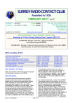
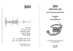
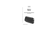
DSP Noise Cancellation bhi Ltd 22 Woolven Close Burgess Hill West Sussex RH15 9RR tel: +44 (0)845 217 9926 fax: +44 (0)845 217 9936 [email protected] www.bhi-ltd.co.uk Page 28 ANEM Operating Manual Sound Engineering Solutions from bhi Sound Engineering Solutions bhi bhi ‘Noise Away’ ANEM MKII Amplified Noise Eliminating Module Installation and Operating Manual 1065-102D Issue E ANEM Operating Manual Page 1 Important Information 6.5 Other products. NCH Noise Cancelling Headphones BBRP Banner Badge Get the message across Easy to program using push buttons on back: no cords, no wires, no software needed. Enter your message and watch it scroll across. These headphones feed an inverted copy of the ambient noise to cancel it out. The headphones effectively remove noise such as blower noise, ambient noise, jet engine noise or music from another room. The headphones are supplied with an aircraft adapter, so you can now listen to the film, or CD player without all the jet engine noise. Also supplied with carry bag. BBRP (Includes 2 CR2032 coin cells) BBAT replacement CR2032 coin cell Applications • ID badge • Club badge • Restaurants • Receptions • Gifts • Stag and Hen nights • DJs • etc... What will yours say? Page 2 ANEM Operating Manual ANEM Operating Manual Page 27 6. Other bhi products. Copyright This publication, including all photographs and illustrations is protected under international copyright laws, with all rights reserved. Neither this manual, nor any of the material within, may be copied or reproduced without the written consent of bhi Ltd. Disclaimer The information in this document is subject to change without notice. bhi Ltd. makes no representations or warranties with respect to the contents hereof and specifically disclaims any implied warranties of merchantability or fitness for any particular purpose. Furthermore, bhi Ltd. reserves the right to revise this publication and to make changes from time to time in the content hereof without obligation of bhi Ltd. to notify any person of such revision or changes. Warning The 3.5mm mono Audio Out socket provides variable audio output for an external speaker (4 or 8 ohm impedance) or mono earphones. The audio level varies according to the volume setting of the equipment that the ANEM is being used with. When you plug mono earphones into the Audio Out socket (stereo earphones can be used with the bhi audio adapter ADP-S001), the SP-PH Switch MUST BE set to the to “PH” position, to prevent the possibility of injury to your ears. Contents 1042 Switch box Allows connection of up to 6 pieces of equipment to one bhi noise elimination speaker or any other extension speaker. (Includes 2 free ALD001 3.5mm audio leads) 6. Other bhi products. 6.4 Audio Adapters and Accessories. Power adapters: 1030-UKPA 12V DC UK power adapter 1030-EUPA 12 VDC European adapter 1030-VEPL Fused vehicle power adapter Audio leads: ALD-001 1.2m 3.5mm - 3.5mm mono lead ALD-002 2.5m 3.5mm - 3.5mm mono lead ALD-003 phono -phono plug ALD-004 3.5mm stereo plug - phono plug ALD-005 3.5mm mono plug - phono plug Audio adapters: ADP-P001 6.35mm plug - 3.5mm mono socket ADP-P002 6.35mm plug - 3.5mm mono socket ADP-P003 3.5mm stereo plug - 3.5mm mono socket ADP-P004 Phono plug - 3.5mm mono socket ADP-P005 2.5mm mono plug - 3.5mm mono socket ADP-P006 2.5mm stereo plug - 3.5mm mono socket ADP-P007 6.35mm stereo plug - 3.5mm stereo socket ADP-P008 3.5mm stereo - aircraft adapter ADP-S001 3.5mm mono socket - 3.5mm mono plug ADP-S002 6.35mm socket - 3.5mm mono plug ADP-S003 6.35mm stereo socket - 3.5mm mono plug ADP-S004 2.5mm stereo socket - 3.5mm mono plug ADP-S005 2.5mm mono socket - 3.5mm mono plug Page 26 ANEM Operating Manual 1. Introduction 1.1 1.2 2. Whats in the box Getting started Mounting options Connections 6 6 7 8 Module Operation 3.1 3.2 3.3 3.4 3.5 4. 4 5 Module Overview 2.1 2.2 2.3 2.4 3. ANEM module features DSP noise cancellation Keyboard 3.1.1 Power button 3.1.2 DSP level button Set up Demonstration modes Noise reduction levels Electrical characteristics 9 9 9 10 11 13 14 Technical Information 4.1 4.2 4.3 4.4 Module layout Controls Module set up 4.3.1 Overview 4.3.2 Suggested adjustment procedure 4.3.3 Changes to output load 4.3.4 Other signal considerations Driving the module from a low signal source 18 19 20 20 20 21 21 22 5. Troubleshooting 23 6. Other bhi products 24 ANEM Operating Manual Page 3 6.3 The ANEM is a compact, easy to use amplified DSP inline module, and simply connects in between the communications equipment and extension speaker. It is suitable for a wide range of applications, but is particularly useful for improving voice quality in amateur radio, removing unwanted noise and interference to give much improved readability and speech intelligibility across all bands. 1. Introduction. The ANEM is suited to customers who prefer simple controls and operation. It also offers a solution for those customers who do not want to fit the NEDSP1062-KBD amplified DSP module inside their existing extension speaker. The ANEM is easy to set up and its functions are microprocessor controlled, enabling simple operation via two pushbuttons: Power on/off audio bypass and DSP filter on/off. 4 or 8 levels of noise cancellation are selectable via the pushbuttons on power up, the last selected filter level remaining in the memory when the unit is switched off. The unit has a Headphone/speaker select switch enabling the module to be used with an extension speaker or a pair of mono headphones (Warning - Do not switch to “SP” position whilst using headphones as this could damage your hearing). The ANEM comes boxed with a Fused DC power lead (2.1mm) and a 3.5mm mono plug lead 1.2m long, plus full operating instructions. Audio adapters are available to suit different connections, and Velcro strips are provided for mounting the module in a suitable position on your extension speaker or radio equipment. Page 4 ANEM Operating Manual NEIM1031MKII In-line module. Then NEIM1031 provides a flexible solution to noise reduction. It features both amplified inputs and outputs, along with line level signal processing. The unit also features an audio bypass when the unit is switched off, so there is no need to disconnect when not in use. Amplified unit with 5Watts audio input & 2.8Watts output Features: • Fully adaptive noise cancellation 9 -35dB • 8 filter levels with new control knob • Mono earpiece socket • Input sensitivity & volume controls • Noise cancellation On/Off switch • Line level in/out • Input overload indication • Power on/off with audio bypass. 6.4 NEIM1031 accessories. LSPKR 20 Watt 4 ohm extension speaker for use with the NEIM1031. Fitted with a 3.5mm mono jack plug. 6.5 1031-STAND Clear Acrylic stand to mount the NEIM1031. The NEIM1031 can be used horizontally or vertically DSP pcb modules. NEDSP1061-PCB: Low level audio module for commercial use. NEDSP1061-KBD: Pre-wired low level audio module controlled by a single button keyboard. NEDSP1062 - KBD: Pre-wired Amplified DSP module controlled by a 2 button keyboard. NEDSP1062 - PCB: Basic amplified DSP module for commercial use. ANEM Operating Manual Page 25 6. Other bhi products. 1. Introduction. 6. Other bhi products Features: 6.1 NES10-2 MKII Noise Eliminating speaker. 6. Other bhi products. DSP noise cancellation built into a compact speaker unit. the unit provides an easy to install solution to noise reduction Features: • Fully adaptive noise cancellation 9 -35dB • 8 user selectable noise cancellation levels • Mono earpiece socket • Input sensitivity control • Noise cancellation On/Off switch • LED indication of power and noise cancellation • 12-24VDC operation • On/Off audio bypass switch. • Greatly improved signal to noise ratio • Easy to install with adjustable mounting bracket • 2m audio lead • Optional extras avaiable. Noise reduction 9 – 35dB Tone reduction 4 – 65 dB Power supply 12 – 18 V dc Input signal > 50mV Output load 2.5W 8ohm Current consumption 300mA Audio bandwidth 50 – 4.3KHz Dimensions (WxDxH) 100 x 60 x 40mm 4 or 8 filter levels (selectable) Visual and audio indication of filter level Audio bypass when switched off 1.2 DSP Noise cancellation. The bhi DSP processes the incoming signal and then differentiates the speech from the noise. The unwanted noise and interference is then attenuated to leave only the speech. The following diagrams are taken from actual audio signals and illustrate how the signal is being processed. Speech Noise Original signal. Speech with a lot of background noise Reduced noise Processed speech. Speech with reduced noise Figure 1. Noise cancellation. Page 24 ANEM Operating Manual ANEM Operating Manual Page 5 1. Introduction. Other noise cancellation products from bhi. Visit www.bhi-ltd.co.uk for more information. Increase supply voltage No Yes DSP function button DSP function LED Reduce input level Finish Yes Audio out? Increase output level P1 No Increase input signal P2 Yes No SP Speaker/ Headphone switch Figure 3. Controls Page 6 Input signal Start Power on/off bypass button Overload LED on Yes Apply audio signal Figure 2. Connectors No Audio In (from equipment) ANEM Operating Manual ANEM Operating Manual Page 23 5. Troubleshooting. Finish Yes Sufficient output volume? Increase output level P1 No Yes Reduce input so LED goes out Yes Over load LED illuminates? Audio out (to loudspeaker) 5.1 No audio out 2. Module Overview. Power connector 12 - 15V dc 300mA centre positive Increase input level Start 2.2 Getting Started. Supply voltage <13.8 Vdc No Over load LED illuminates? Disconnect R6 (see section 3.3) ANEM MKII module Fused DC power lead 3.5mm mono leads Operating manual Self adhesive rubber feet Hook and eye fastener strip Input level too low 1 off 1 off 1 off 1 off 4 off 1 off No Add additional amplification 2.1 Whats in the box. The ANEM is supplied with the following. Please check that all of the items are present. 5.2 Insuffucient output volume 5. Troubleshooting 2. Module Overview. 4.4 Driving from a low signal source. 2.3 The input to the module has a low impedance. This is to provide correct loading to any power circuits driving it. If the module needs to be driven from a low power signal then it must be modified in the following manner. The case must first be removed, as described in section 4.2. Note: Wiring and heatsink omitted for clarity. The ANEM can be used on the bench, or attached to your loudspeaker using the velcro strips supplied. For bench mounting attach the four rubber feet to the bottom of the module as shown. If the module is going to be mounted on the loudspeaker then attach the strip of hook and eye fastener as shown below. hook and eye fastener strip 4 off rubber feet fit over case screws Figure 16. Physical modification for low power signal drive. Circuit modification Figure 4. Mounting options 10 OUT 9 IN Audio Input Mount it on the side... R6 22W V Agnd ..on the top.. Load 12 Agnd 11 ..on the back.. ..or use it on the bench... Figure 17. Circuit modification for low power signal drive. Page 22 ANEM Operating Manual ANEM Operating Manual Page 7 2. Module Overview. 4. Technical Information. Cut the leg on this resistor Mounting options. + Audio Source Audio In Audio Out ANEM - 2. Module Overview. Figure 5. Block diagram Speaker or headphones Power Connect the 3.5mm mono lead supplied to the extension speaker socket of your equipment and the audio in socket on the ANEM. Connect a loudspeaker or headphones to the audio out socket on the ANEM. Warning: The 3.5mm mono Audio Out socket provides variable audio output for an external speaker (4 ohm - 8 ohm impedance) or earphones. The audio level varies according to the volume setting of the equipment that the ANEM is being used with. When you plug mono earphones into the Audio Out socket (stereo earphones can be used with the bhi audio adapter ADP-S001), the SP-PH toggle switch MUST BE set to the “PH” position, to prevent the possibility of injury to your ears. Look in section 8 for audio adapters to suit most equipment and applications. Connect the fused DC power lead to a power supply capable of providing 12 - 18VDC @ 300mA. The centre pin of the power connector is positive (the lead with the white stripe is positive). If you require a separate power supply then refer to section 8 for details. The unit is now ready for use. Page 8 ANEM Operating Manual 4.3.3 Change to output load. The audio input to the module is loaded at 22W. This load is effectively connected across the output load when the unit is switched off (bypassed). This will reduce the impedance presented to the audio source. For example: 8W will reduce to 5.9W 4W will reduce to 3.4W 10 OUT 9 IN Audio Input R6 22W V Load Agnd 12 Agnd 11 Figure 15. Input circuit module powered down 4.3.4 Other signal considerations. The ANEM requires a signal of 125mV rms or greater for optimum performance. Signals lower than this may be used but the noise cancellation performance will decrease, as the signal levels drops. If the unit is used with low level signals such as microphones, the signal will need amplifying before applying it to the ANEM. Due to the adaptive nature of the noise cancellation a small delay may be heard when the audio signal changes. For optimum performance provide the module with a constant signal where possible. When switching on the unit a small audio thump may be heard in the loudspeaker or headphones. ANEM Operating Manual Page 21 4. Technical Information. 2.4 Connections. The ANEM is connected in-line between the equipment and the loudspeaker or headphones, as shown in the following block diagram. 4.3 Module setup. The module is factory set but both the input and output levels are adjustable on the module. This allows easy integration into target systems. If you need to adjust the module follow the instructions below. 4.3.1 Overview. To obtain the best results from the noise reduction the module should be set up to give optimum performance. The input sensitivity control has a range of 0.70mW 3W to provide 2W (W)output. Under certain conditions, RF breakthrough can sometimes occur. To minimize this, the input level (P2) may need to be reduced or go to the FAQ page on the bhi website and download the FAQ on RF breakthrough. Under certain conditions the DSP can create a small amount of noise, you should not be able to hear this noise when a signal is applied to the module. 4.3.2 Suggested adjustment procedure: Basic adjustment procedure. Open the unit by carefully pulling both sides of the bottom half outwards & easing the top half upwards. Ensure that the pcb is clear for any adjustments. Connect input source and output device. Ensure the ANEM is switched off. Set the audio source to a typical audio level. Switch on the ANEM. Adjust the input control (P2) until the overload LED illuminates. Reduce the level by approx. 1/4 turn. Adjust the output level (P1) to the desired level. Hold down the DSP button and adjust the volume of the sounder to suit using P3. Page 20 ANEM Operating Manual 3.1 Keyboard. The keyboard has 2 buttons and a tricolour LED. 3.1.1 Power button. The power button switches the module on and off. When the module is off, the audio bypasses the module, so the circuit will behave as if the module isn’t present. Switching the power on routes the audio through the module. Note: If the power is on and the DSP is switched off, the audio still passes through the DSP - but without any signal processing. A single press on the button switches the power on, and a single press will switch it off. Also with the power connected and the module switched off the circuit will draw 6mA. 3.1.2 DSP level button. This button is used to set the following: • DSP on/off • DSP level • 4 or 8 levels of noise cancellation • Demonstration modes Power on/off bypass button DSP function button DSP function LED Figure 6. Controls ANEM Operating Manual Page 9 3. Module Operation. 4. Technical Information. 3. Module Operation. 3.2 Set up. The following flow chart shows the functions of the DSP button. Power up DSP button pressed Turning the potentiometers clock wise will decrease the levels. These potentiometers do not have end stops, so it is possible to set them in a position where the audio will be lost. 2 tone sound Releasing the DSP button at this point the module goes in to demonstration mode 1 DSP button pressed No Demonstration 1 Yes 3. Module Operation. 2 tone sound Releasing the DSP button at this point the module goes in to demonstration mode 2 DSP button pressed The level controls provide adjustment for the audio levels entering and leaving the module. The modules are factory set to the maximum level. No Yes This is indicated by a 2 tone beep. Controls. No Audible indication of operation is provided by an piezo sounder. The volume of this sounder can be varied by potentiometer P3. The sounder volume is independent of the incoming audio volume. Demonstration 2 Yes 2 tone sound DSP button pressed No Yes 2 tone sound Keep the button down until the desired level has been reached, then release the button. The module will continously scroll through 4 and 8 levels until the button is released. beep number of DSP levels Yes Change 4 or 8 levels Yes DSP button pressed DSP button pressed No The input to the module is loaded at 22W to provide a dummy load to the preceding circuit. This can be removed if required, such as using the module in applications where the audio source is provided by a low level, low power signal source. More information on this can be found in section 3.3 in this operating manual. If Vin is less than approx. 13.8V ensure the power supply is well decoupled otherwise the power supply rejection ratio will deteriorate. Best results are obtained in the range of 13.8V - 16Vdc. No Normal operation Figure 7. 4/8 level setting. Page 10 ANEM Operating Manual ANEM Operating Manual Page 19 4. Technical Information. Holding down the DSP button when switching on causes the module to enter the set up mode. 4.2 4. Technical Information. 4.1 Module Layout. In order to access the printed circuit board the case needs to be removed. To do this, ensure the module is Off. Press and hold the DSP level button. Turn on the module and a 2 tone beep will be heard indicating that the module is in the set up mode. Releasing the button after the first 2 tone beep will enter demonstration mode 1. Figure 13. ANEM case dis-assembly detail. The following diagram shows the internal layout of the ANEM printed circuit board. Note: Wiring and heatsink obmitted for clarity Input level set (P2) Audio bypass relay Output level set (P1) Sounder volume (P3) Releasing after the second 2 tone beep will enter demonstration mode 2. Keeping the button depressed with change the number of levels available. 4 beeps will indicate 4 level mode and 8 beeps 8 levels. Release the button when the desired level is reached. The module will return to normal operation after this. The colour of the LED will indicate the mode of operation. DSP mode 4 Levels 8 Levels OFF RED ORANGE ON GREEN GREEN Table 1. LED mode indication. Figure 14. ANEM PCB and controls Page 18 ANEM Operating Manual ANEM Operating Manual Page 11 3. Module Operation. 4. Technical Information. Carefully pull the sides of the case outwards, until the upper section can be removed. When reassembling the module enusre that none of the wires become trapped in the case halves. Input overload indicator LED To listen to the demonstration modes, or change the number of DSP levels it is necessary to put the module into the set up mode. 3.3 Demonstration modes. Start Start Noise cancellation On Noise cancellation On Wait 3 Seconds Wait 1.5 Seconds Noise cancellation off Noise cancellation off Wait 3 Seconds Increase DSP noise cancellation level DSP button pressed? Yes 3. Module Operation. 2 tone beep Figure 8. Demonstration modes. No Highest Level? 4. Technical Information. No This page is left blank Yes Normal operation Normal operation Demonstration 1. The module switches the noise cancellation on for 1.5 seconds, then off for 1.5 seconds. It will then move to the next level and repeat the process. This mode is particularly effective at demonstrating the different DSP levels. Alternatively pass a clean audio signal through the module to see hear how little the DSP alters the speech. Page 12 Demonstration 2. The module switches the noise cancellation on for 3 seconds then off for 3 seconds. This is a good demonstration of the before and after effects of removing the noise. Note: To exit the demonstration modes hold down the DSP button until a 2 tone beep is heard. ANEM Operating Manual ANEM Operating Manual Page 17 3.4 Figure 11. Sensitivity. Output power (W) VS = 16V f = 1KHz RL = 8W 1.5 L evel (4) 1 RL = 4W 0.5 1 0 0 50 100 150 200 2 Input voltage (mV) 3 3. Module Operation. 4 L evel (8) Tone Reduction White Noise Reduction 1 4dB 9dB 2 5dB 11dB 3 6dB 13dB 4 8dB 15dB 5 16dB 17dB 6 21dB 20dB 7 25dB 24dB 8 65dB 35dB Table 2. Tone and noise reduction levels. Section 4 contains information on adjusting the operation of the ANEM. The module is supplied factory set and under normal circumstances no further adjustment is necessary. The following information is for guidance only and any adjusments to the DSP circuit should only be carried out by those who have a technical understanding of what they are doing. The column marked level (4) shows the noise and tone reduction when operating the module with 4 levels, and the level (8) column for 8 levels. Holding down the DSP select button will continuously change the DSP level. When the desired level has been reached, release the button. The module will retain this level until it is changed. The ANEM is factory set up and ready for use. If you are using the module in an application which requires adjustment. For the optimum performance refer to section 4 for more information. Page 16 ANEM Operating Manual ANEM Operating Manual Page 13 3. Module Operation. 4 or 8 levels of noise reduction are available. The amount of noise and tone reduction is shown in the table below. 2.5 2 Noise reduction levels. 3.5 Electrical characteristics. Figure 9. Frequency response 5 ELECTRICAL CHARACTERISTICS i (Vs=16V, Tamb= 25 C unless otherwise stated) 0 0 Symbol Parameter Test Conditions Min. Typ. Max. Units 12 16 18 V Vs Supply voltage Iqs Quiescent current V s = 12V V s = 16V V s = 18V 4.6 6.8 7.1 mA Iqon Quiescent current DSP on no load no signal V s = 12V V s = 16V V s = 18V 143 160 161 mA 2000 3000 4000 5000 6000 -3dB -5 VS = 16V RL = 8W -15 P = 1W -20 Frequency (Hz) Test Conditions d = 10% f = 1KHz Min. Typ. Max. Units 12V 16V 18V Vs 2.06 3.17 W W Po Output power Vi Input sensitivty 4W W load Vi Input sensitivty 8W W load B Frequency response (-3dB) P o = 1W RL = 8W d Distortion f = 1KHz PO = 0.2 - 2.4W R L= 8W PO = 0.2 - 2.4W R L= 4W Ri Input resistance Gv Voltage gain f = 1KHz 27 dB n Efficiency f = 1KHz PO = 3W R L = 4W PO = 2W R L = 8W 33 38 % RL = 8W RL = 4W 1.16 1.7 PO = 0.5W PO = 1.0W PO = 2.0W 60 90 130 PO = 0.5W PO = 1.0W PO = 2.0W 81 117 180 mV Figure 10. Distortion vs. Output power f = 1KHz 50 4300 0.8 0.8 21 22 Td Parameter Test Conditions Hz % W 23 RL = 8W 8 6 4 RL = 4W 2 0 0 0.5 1 1.5 2 2.5 3 3.5 Output power (W) Min System delay VS = 16V f = 1KHz 10 ANALOGUE CHARACTERISTICS Symbol 12 mV Typ 26 Max. Units mS Table 3. Electrical characteristics 1 Page 14 ANEM Operating Manual ANEM Operating Manual Page 15 3. Module Operation. f = 1KHz Distortion 3. Module Operation. Parameter 1000 -10 AC CHARACTERISTICS Symbol Output (dB) DC CHARACTERISTICS