1
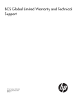
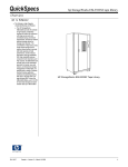
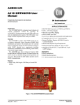
hp rp2400 Series of Servers
Basic Cable Connections
Version 2.0
Manufacturing Part Number: rp24xx_basic_cable-en
January 2004
U.S.A.
© Copyright 2002-2004 Hewlett-Packard Development Company, L.P..
Legal Notices
Copyright Notices. © Copyright 2002-2004 Hewlett-Packard Development Company, L.P.
The information contained herein is subject to change without notice. The only warranties for HP products
and services are set forth in the express warranty statements accompanying such products and services.
Nothing herein should be construed as constituting an additional warranty. HP shall not be liable for
technical or editorial errors or omissions contained herein.
Printed in the U.S.A.
Reproduction, adaptation, or translation of this document without prior written permission is prohibited,
except as allowed under the copyright laws.
Related Documents. For online access to technical support information, self-solve tools, online assistance,
community forums of IT experts, broad multivendor knowledge base, and monitoring and diagnostic tools, go
to http://www.hp.com/support.
IMPORTANT The latest versions of these documents, and any updates to these documents, are posted under
the appropriate server at http://docs.hp.com.
HP Encourages Your Comments
HP encourages your comments concerning this document. We are truly committed to providing
documentation that meets your needs.
Please send any comments by contacting us at http://docs.hp.com/assistance/index.html.
Please include document title, manufacturing part number, and any comment, error found, or suggestion for
improvement you have concerning this document.
2
Contents
1. HP rp2400 Series of Servers Basic Cable Connections
Record System Serial Number . . . . . . . . . . . . . . . . . . . . . . . . . . . . . . . . . . . . . . . . . . . . . . . . . . . . . . . . . . 7
Front Panel Controls and indicators. . . . . . . . . . . . . . . . . . . . . . . . . . . . . . . . . . . . . . . . . . . . . . . . . . . . . . 8
Server External Connections . . . . . . . . . . . . . . . . . . . . . . . . . . . . . . . . . . . . . . . . . . . . . . . . . . . . . . . . . . 8
Connecting PDU(s) to Dedicated AC Input Receptacles . . . . . . . . . . . . . . . . . . . . . . . . . . . . . . . . . . . . . 10
Console Connection and Configuration . . . . . . . . . . . . . . . . . . . . . . . . . . . . . . . . . . . . . . . . . . . . . . . . . . 11
rp24xx Server RS-232 System Local Console Installation . . . . . . . . . . . . . . . . . . . . . . . . . . . . . . . . . . 12
Console Configuration (VT100 mode) . . . . . . . . . . . . . . . . . . . . . . . . . . . . . . . . . . . . . . . . . . . . . . . . . . 12
3
Contents
4
Figures
Figure 1-1. Serial Number Locations . . . . . . . . . . . . . . . . . . . . . . . . . . . . . . . . . . . . . . . . . . . . . . . . . . 7
Figure 1-2. Controls and LED Indicators . . . . . . . . . . . . . . . . . . . . . . . . . . . . . . . . . . . . . . . . . . . . . . . 8
Figure 1-3. External Connections to the Server . . . . . . . . . . . . . . . . . . . . . . . . . . . . . . . . . . . . . . . . . . 9
Figure 1-4. Console Connection and Configuration . . . . . . . . . . . . . . . . . . . . . . . . . . . . . . . . . . . . . . 11
Figure 1-5. Console/Remote-Modem/UPS Connector . . . . . . . . . . . . . . . . . . . . . . . . . . . . . . . . . . . . . 12
5
Figures
6
1 HP rp2400 Series of Servers Basic Cable Connections
To make the basic cable connections for the rp24xx Server, refer to the illustrations and instructions below.
For detailed installation, maintenance, and technical information, refer to the rp24xx Hardware Manual and
other documentation (search on rp2400) at http://docs.hp.com.
Record System Serial Number
Before proceeding further with this installation, locate and record the system serial number and store in a
safe place. The serial number will be required for warranty and service work.
The serial number is located in two places as shown in the graphic below:
Figure 1-1
Serial Number Locations
Serial Number Tag
wi n Path: 0/2/0
urbo
100-240V~, 600W
6.0-2.6A, 50-60Hz
wi n Path: 0/4/0
urbo
GSP Reset TO C
A
B
Ultra 2 W ide SCSI
Path: 0/0/1/ 0
ccrr012
Chapter 1
Narro w S ingle Ended SCSI
Path: 0/0/2/ 0
10/100BASE- T 10BASE- T
Path: 0/0/0/ 0 LAN Consol e
Console/
UPS Por t
Path: 0/6/2
Path: 0/6/ 0
Pull-Out Tab
7
HP rp2400 Series of Servers - Basic Cable Connections
Front Panel Controls and indicators
Front Panel Controls and indicators
The following section describes the controls and LED indicators at the front of the rp24xx Server as shown in
the following graphic:
Figure 1-2
Controls and LED Indicators
Run
Attn.
Fault
Remote
Power
ccrr018
1. (Green) RUN LED - When lit, indicates that the system is powered-up.
2. (Amber) Attention (ATTN) LED - When lit, indicates that a condition exists that requires operator
attention and assistance from HP Support.
3. (Red) Fault LED - When lit, indicates that a condition exists that requires immediate operator action.
4. (Amber) Remote LED - When lit, indicates that the remote ports are active.
5. (Green) Power LED - When lit, indicates that the system has DC power enabled.
NOTE
For technical support please call your local support hotline or contact HP at
http://www.hp.com/support.
Server External Connections
External devices are interfaced with the server by means of specific connectors located on the rear bulkhead.
Exterior connections to the server include ports for:
•
Small Computer System Interface (SCSI) devices
•
System Console
•
Local Area Network (LAN) Console
•
LANs
•
Power Cord
8
Chapter 1
HP rp2400 Series of Servers - Basic Cable Connections
Front Panel Controls and indicators
The graphic shown below illustrates locations of the external connections to the server.
Figure 1-3
External Connections to the Server
100-240V~, 600W
6.0-2.6A, 50-60Hz
On/Off
Switch
win
urbo
GSP Reset
Path: 0/2/0
win
urbo
Console/
UPS Port
TOC
wi n Path: 0/2/0
urbo
100-240V~, 600W
6.0-2.6A, 50-60Hz
Path: 0/4/0
wi n Path: 0/4/0
urbo
GSP Reset TO C
A
B
Ultra 2 W ide SCSI
Path: 0/0/1/ 0
Narro w S ingle Ended SCSI
Path: 0/0/2/ 0
10/100BASE- T 10BASE- T
Path: 0/0/0/ 0 LAN Consol e
Console/
UPS Por t
Path: 0/6/2
Path: 0/6/2
Ultra2 Wide SCSI
Path: 0/0/1/0
A
B
Narrow Single
Ended SCSI
Path: 0/0/2/0 10/100BASE-T
Path: 0/0/0/0
10BASE-T
LAN Console
Path: 0/6/0
Path: 0/6/0
Pull-Out
Tab
ccrr008
Connect External Small Computer System Interface (SCSI) Devices
Connect external SCSI devices to the single ended SCSI bus (labeled: Narrow Single-Ended SCSI Path:
0/0/2/0) on the system card or to the Ultra 2 SCSI bus (labeled: Ultra 2 SCSI Path: 0/0/1/0).
Ensure that all devices on the SCSI bus have a unique address and the last device is terminated. Refer to the
documentation accompanying each device to learn how to set addresses and where to place terminators.
Connect a System Console
NOTE
For more information on console configuration, refer to the rp24xx Hardware Manual (search
on rp2400) at http://docs.hp.com.
•
Using the ASCII Terminal as a System Console. If an ASCII terminal is to be used as a console/UPS
port, make sure that the keyboard is connected and a power cable is available.
•
Using a Secure Web Console PCI card as a System Console. If the Secure Web Console PCI card is
to be used as a system console, first configure the Guardian Service Processor (GSP). For more
information on GSP configuration, refer to the rp24xx Hardware Manual (search on rp2400) at
http://docs.hp.com.
Then, connect an RJ45 LAN cable to the Secure Web Console PCI card installed in an I/O card slot on the
back of the server.
Chapter 1
9
HP rp2400 Series of Servers - Basic Cable Connections
Connecting PDU(s) to Dedicated AC Input Receptacles
NOTE
•
The Web Console has a default Internet Protocol (IP) address of 192.0.0.192 for rp2400
and rp2450 servers, and 127.0.0.1 for rp2430 and rp2470 servers. Make sure that no
other device, including other rp24xx servers, has this address before connecting the server
to your LAN.
Using the LAN Console as a System Console. If a LAN Console is to be used as a system console, first
configure the Guardian Service Processor (GSP). For more information on GSP configuration, refer to the
rp24xx Hardware Manual (search on rp2400) at http://docs.hp.com.
Then, connect it to the system with an RJ45 LAN cable to the RJ45 connector labeled 10BASE-T LAN
Console connection on the back of the server.
Connect the Core Local Area Network (LAN)
Connect the 10/100BASE-T Core LAN on the system board to the LAN with an RJ45 LAN cable. Connect the
RJ45 LAN cable to the server by attaching it to the RJ45 connector labeled 10/100 Base-T Path: 0/0/0/0.
Connect Power Cords
Connect the power cord that is provided with the system to the server. For stand-alone servers, the power cord
will be localized to each country’s power application. If an HP Uninterruptible Power Supply (UPS) is the
power source, use the power cord provided with the UPS.
Connect power cords to all external devices at this time with the either the localized power cord, cabinet
Power Distribution Unit (PDU) power cord, or the UPS power cord.
For cabinet-mounted servers, the server power cord connects to the PDU in the cabinet.
Connecting PDU(s) to Dedicated AC Input Receptacles
In non-HA installations, each PDU should be plugged into a separate dedicated 20amp AC receptacle.
NOTE
If the rp24xx server is installed as a standalone, the specialty convenience cord (provided) may
be plugged into either wall outlets with appropriately sized breakers, or a plug strip capable of
providing the total current required for your server’s configuration.
Current requirements vary with input voltage, server configuration, and number of power
supplies installed. Refer to “System Site Preparation” in the rp24xx Hardware Manual at
http://docs.hp.com.
10
Chapter 1
HP rp2400 Series of Servers - Basic Cable Connections
Console Connection and Configuration
Console Connection and Configuration
The following describes of the installation and configuration of the rp24xx server console.
Figure 1-4
Console Connection and Configuration
To Console/UPS
port at rear server
A5191-63001
COMPUTER
25-Pin
UPS
9-Pin
REMOTE
9-Pin
9-Pin
CONSOLE
9-Pin
9-Pin
OR
A5858-63001
CABLE
9-Pin
To optional built-in (PCI)
Secure Web Console
24542G
CABLE
25-Pin
To Local VT-100
Console
cons_connect_config
Chapter 1
11
HP rp2400 Series of Servers - Basic Cable Connections
Console Connection and Configuration
rp24xx Server RS-232 System Local Console Installation
The following describes how to install a system console on an rp24xx Server. The HP-700 series terminal is
used as an example. Other terminals may be used as a system console as long as they are configured for
VT100 terminal emulation mode.
1. Connect the 25-pin end of the A5191-63001 adapter cable to the 25-pin connector on the Console/UPS Port
located on the rear.
2. Connect the 9-pin, “Console,” connector of a A5191-63001 adapter to the 9-pin D-type connector on a
24542G RS-232 cable.
Figure 1-5
Console/Remote-Modem/UPS Connector
wi n Path: 0/2/0
urbo
100-240V~, 600W
6.0-2.6A, 50-60Hz
wi n Path: 0/4/0
urbo
GSP Reset TO C
A
B
Ultra 2 W ide SCSI
Path: 0/0/1/ 0
ccrr012
Narro w S ingle Ended SCSI
Path: 0/0/2/ 0
10/100BASE- T 10BASE- T
Path: 0/0/0/ 0 LAN Consol e
Console/
UPS Por t
Path: 0/6/2
Path: 0/6/ 0
Console/Remote-Modem/UPS Connector
(D-Type 25-Pin female)
Requires: A5191-63001 “W” adapter cable
3. Connect the 25-pin end of the 24542G serial cable to the serial/RS232 port on the Console. (RS232 Serial
Port labeling may vary depending on manufacturer.)
4. Connect the System Console to input AC power.
5. Turn the System Console AC power switch to ON.
Console Configuration (VT100 mode)
The following describes the steps required to configure system consoles for VT-100 mode for operation with
the rp24xx server.
C1099A VT-100 Mode Configuration.
The following procedure outlines the steps to configure the C1099A terminal for VT-100 operation.
To access the Setup menu in HPTerm emulation:
1. Press the F10 key to display the terminal local function labels, then Press F8 (config keys).
You are now in the Quick (F1) menu.
2. Select the VT100 emulation by using the space bar to navigate through the available options.
3. Press the ESC key to save selected setup parameters and to exit the Setup menu.
4. Press the Y key when the blinking prompt
Save all? (Y/N)
appears in the upper right corner of the menu to save the settings in non-volatile memory.
12
Chapter 1
HP rp2400 Series of Servers - Basic Cable Connections
Console Connection and Configuration
NOTE
If you enter N when the
Save all? (Y/N)
prompt appears, the changes will take effect, but will be lost if the terminal is reset or
powered off.
HP700 VT-100 Mode Configuration
The following procedure outlines the steps to configure the HP700 series terminal for VT-100 operation.
NOTE
You may use either the arrow keys or the tab key to move between the setting options on the
screen.
Be sure to save any configuration changes you make before proceeding to a new menu.
1. Press [User System] key.
2. Press [config keys] function key. [f8]
3. Press [terminal config] function key. [f5]
4. Move to Terminal ID and enter “vt100”.
5. Move to TermMode and, using the [Prev] and [Next] keys, select “EM100”.
6. Save the configuration. [f1]
7. Press the [config keys] function key. [f8]
8. Press the [ansi config] function key. [f6]
9. Move to multipage and, using the [Prev] and [Next] keys, select “yes”.
(Enables screen scrolling).
10. Move to Backspace Def and, using the [Prev] and [Next] keys, select “Backspace/Del”.
11. Move to EM100 ID and, using the [Prev] and [Next] keys, select “EM100”.
12. Save the configuration.[f1]
rp24xx Server Optional PCI Web Console Cable Setup
The following describes how to install the cabling for the optional built in (PCI) web console:
•
Connect the 25-pin end of the A5159-63001 adapter cable to the 25-pin connector on the Console/UPS Port
located on the rear of the rp24xx server.
•
Connect the 9-pin, “Console”, connector of a A5159-63001 adapter to a A5858-63001 adapter.
Plug the other end of the A5858-63001 adapter to the 9-pin connector on the optional built-in PCI web console
card.
Chapter 1
13
HP rp2400 Series of Servers - Basic Cable Connections
Console Connection and Configuration
14
Chapter 1