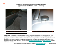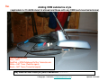
1
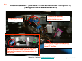
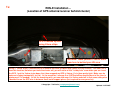
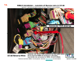
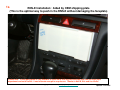
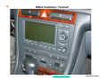
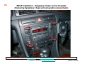
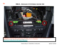
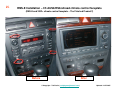
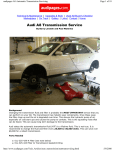
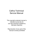
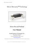
1a.
TeddyBGame RNS-E install:
1)Slight modifications to plug/play adaptor
2)Upgrading the climate control faceplate to the
2002+ color (optional activity)
3)Building plug/play adaptor for OEM SAT tuner
and OEM Phatbox or Ipod IceLINK or
Blitzsafe audio interface (optional activity)
Please note: A majority of these pictures are applicable to a pre2002 C5 A6/S6/allroad, but can be useful for all 2002+ C5 A6’s and
other Audi models. Enjoy!
Standard disclaimer: You do all these upgrades at your own risk
to your car and your factory Audi warranty. ☺
Contributing Editor:
Lee Hicks (NSX Jr)
© Copyright – Ted Basile ( [email protected] )
Updated: 12/27/2005
1b.
RNS-E Installation (Front view of Head unit) –
Euro “P” and US “R” unit for C5 A6
Euro “P” unit
Audi Part#: 4B0-192-035P
US “R” unit
Audi Part#: 4B0-192-035R
Please note: These pictures were borrowed from a B6/B7 A4/S4….but you get the general idea. ☺
Courtesy – Ted Basile ( [email protected] )
Updated: 12/27/2005
1c.
RNS-E Installation (AM/FM and GPS antenna/connectors) –
Preparation for conversion from Symphony I/II to RNS-E
Use for conversion from
Symphony I or Concert to RNS-E
Use for conversion from
Symphony II to RNS-E
Standard aftermarket GPS
antenna with FAKRA
© Courtesy of KUFATEC.de
Updated: 12/27/2005
1d.
RNS-E Installation (Rearview of Head unit) – for C5 A6 Community
Connection for:
- Dietz 1417 (A/V interface) or
- Dietz 1215 (Audio interface)
Special Thanks to Avantiex for these pictures
Updated: 12/27/2005
1e.
RNS-E Installation (The plug/play interface harness)
Please note: When you order your plug/play harness from your broker/supplier, you need to specify if your Audi has:
1) Bose or Non-Bose (very important as the wiring is slightly different)
2) OEM CD Changer or not (if you plan on connecting a trunk mounted CD changer, Phatbox, OEM SAT tuner, IceLink or other
audio input device now, or in the future; it’s best to have your harness pre-made for the changer).
3) Telephone: In my opinion, it couldn’t hurt to have your harness pre-wired for this in the event that you want to add an
aftermarket or OEM Bluetooth hands-free kit later in the future.
Special Thanks to Avantiex for these pictures
Updated: 12/27/2005
1f.
RNS-E Installation – Typical plug/play harness
(Preparation for conversion from Symphony I environment)
I removed the “phone connector” and left Mute, Speaker +/ wires to run just these three wires down to my lower dash
area for future Bluetooth hands free kit.
GALA/Speed sensor wire - will be cut and a
switch will be added here for “video-inmotion” for use with my Dietz 1417 A/V
interface. Note: disabling the speed signal
will impact your navigation performance.
© Copyright – Ted Basile ( [email protected] )
Updated: 12/27/2005
1g.
RNS-E Installation –
(Hardwire Connectors II and III to create more “space” behind RNS-E in C5 A6)
Connector II:
4 male pins/wires mated with factory harness
(passive front speakers)
Connector III:
4 male pins/wires mated with factory harness
(GALA wire, ground, constant battery and Kline/VAG/Diagnostic)
Please note: This is an optional step. In my install, I have a Dietz 1417 A/V interface and this added some additional “bulk”
behind the RNS-E. Therefore, I decided to remove the male pins/wires (using my special wire extraction tool) from these two 8pin connectors and mate them with the female pins/wires from the factory harness behind my radio. I did not cut any wires from
the plug/play connector – I used heat shrink tubing to cover the wires.
© Copyright – Ted Basile ( [email protected] )
Updated: 12/27/2005
1h.
RNS-E Installation – Plug/Play harness
(items to note for Symphony I and II conversions for the C5 A6)
For a Sym II (2002+ C5), you will need to
add a female wire/pin to the factory
harness (Connector III, pin location #1;
Audi part# is: 000-979-133) for running the
GALA/Speed signal from behind the
instrument cluster.
GALA
/S
needs peed senso
r wire
to be
prese
nt her
e!!!
Connector IV / Phone connector:
This is the location of the three wires
needed to interface an aftermarket
hands-free kit.
Courtesy of Ted Basile ( [email protected] )
Updated: 12/27/2005
1i.
RNS-E Installation
(Removing Symphony I or II head unit using radio removal tools)
These tools can be purchased on www.ebay.com or via www.samstagsales.com. The part number is T10057.
© Copyright – Ted Basile ( [email protected] )
Updated: 12/27/2005
1j.
RNS Installation
(Female connectors found behind your Symphony I & II head unit)
Please Note: In a Symphony II head unit
(MY2002-2004 A6/S6/allroad/RS6),
connectors II and IV may not be present. Most
with Bose won’t have connector II.
Connector IV –
10 Pin (Red)
Connector I –
20 Pin
Alarm Ground
(add male spade
connector and run wire
to D14 in RNS-E harness)
Connector II –
8 Pin (Brown)
AM/FM diversity
antenna connections
Connector III –
8 Pin (Black)
I highly recommend putting some electrical or painters’ blue tape on the top edge of your climate control unit as you
can easily “scuff” or mark it during installation.
© Copyright – Ted Basile ( [email protected] )
Updated: 12/27/2005
1k.
RNS-E Installation (The Female 20 pin connector for Symphony I and II)
20 pin (Connector I) split into three distinct sections:
- Blue: 8 pins for OEM CD Changer, PhatBox or Blitzsafe
or IceLINK interface etc.
- Green: 6 pins for various functions (CAN H, CAN L etc)
- Yellow: 6 pins for line-level output to Bose or
aftermarket amplifier
There are clips on the
other side of these
holes that allow you
to slide these
connectors off from
each other.
20 pin (Connector I) typically found as one unit:
I relocated the pins to the blue/green/yellow version
for a “modular” approach to upgrading to the RNS-E.
In connector I, you only need to slide a purple
“locking bar” out a bit to remove/add any female
pins.
You’ll need to remove this yellow “locking bar” in connectors II, III
and IV (use an exacto-knife or razor blade) before
removing/adding any female pins.
© Copyright – Ted Basile ( [email protected] )
Updated: 12/27/2005
1l.
RNS-E Installation – 20 Pin connector/pins (Symphony I only)
20 Pin Connector (blue/green/yellow version) and female wire/pin
Audi Part#:
4A0 972 643B
(CDC input etc)
Audi Part#:
4A0 972 643A
(control for MFSW,
cluster etc.)
Audi Part#:
4A0 972 643
(line out to amp etc)
Add three female pins:
Audi Part#:
000 979 131
#7 = CAN H, #12 = CAN L
(both from instrument cluster)
#10 is for CD Changer GND
(connect from red 10 pin
connector to avoid potential
operation issues with CDC,
Phatbox etc.)
Please note: If you have a Symphony I, you might want to consider moving some pins from the one-piece black 20 pin
connector to the multi-colored version (above). This way, you can retain the factory location of the pins in location 7-12 and
make room to plug in the CAN H/L wires from the instrument cluster. I used two of these green connectors to keep some of
the original pins for the Symphony I; I then tucked it behind the radio so that I can plug it back in place in the event that I want
to replace my Symphony I and return it to stock.
Courtesy of Ted Basile ( [email protected] )
Updated: 12/27/2005
1m.
RNS-E Installation - (Audi/VW wire extraction tools - very useful if you
don’t want to cut any factory wires)
Used for removing the female pins
from 20 pin – Connector I (approx. $125)
Used for removing the female pins from
8/10 pin – Connector II, III and IV (approx. $125)
Please note: I have purchased both of these tools and
can lend them to anyone in North America. Feel free to
contact me at [email protected] .
Courtesy of Ted Basile ( [email protected] )
Updated: 12/27/2005
1n.
RNS-E Installation (custom cluster interface harness) –
Preparation for conversion from Symphony I environment
A second set of CAN H & L wires were spliced
into this harness (and left under the lower dash
area) for future installation of:
• OEM SAT (XM or Sirius) tuner and/or
• OEM BlueTooth cell phone kit and/or
• Dietz A/V interface
or other devices that require an interface in to
the CANbus network.
CAN H & L wires will be
routed to the 20 pin
connector behind my
RNS-E
Routed to the
instrument cluster for
CAN H & L interface
Audi Part#: 000-979-018
© Copyright – Ted Basile ( [email protected] )
Updated: 12/27/2005
1o.
RNS-E Installation
(Removing drivers’ side lower dash)
1
5
4
3
2
You’ll have to unhook the VAG
Interface and two wires from a lower
dome light before the lower dash can
be removed….very easy.
Using an 8MM socket wrench you’ll need to unscrew the following screws to be able to remove the
lower dash. I recommend following this order..and reinstalling in reverse order.
Screw#1 is behind the fuse box panel. Screws #4/#5 are underneath the upper trim plate.
© Copyright – Ted Basile ( [email protected] )
Updated: 12/27/2005
1p.
RNS-E Installation –
Preparation for removing the Instrument Cluster (2003 C5 A6 pictured)
I highly recommend
protecting your steering
wheel and column by
putting down blue
painters’ tape. The two
bottom screws of the
instrument cluster can dig
into your steering wheel
column as you are
removing it.
© Copyright – Ted Basile ( [email protected] )
Updated: 12/27/2005
1q.
RNS-E Installation in C5 A6/S6/allroad/RS6
(Removing the Instrument Cluster)
Remove these two philips head screws. FYI - They
are on tight, so make sure you have the correct size
Phillips head; you don’t want to strip that screw
head or you’ll need to drill them out. ☺
Symphony I
Cluster will come out like this.
Use a flathead screwdriver to
rotate-up the purple tab on the
blue connector first. Do same
for grey and green connectors,
in that order. Install in reverse
order.
To avoid scratching
your steering column
make sure to cover it
with blue painters’ tape.
Symphony II
With the cluster out, you should see the blue, grey
and green Instrument cluster connectors.
With the cluster out, you should see the blue, grey
and green Instrument cluster connectors.
© Copyright – Ted Basile ( [email protected] )
Updated: 12/27/2005
1r.
RNS-E Installation – another option for removing the cluster
(Rear of C5 A6 Instrument Cluster)
The cluster can also be removed by reaching up underneath the lower dash to push it out. In order to do this, the
two phillips screws need to be removed and the drivers’ side lower dash panel needs be removed. This will prevent
you from needing to pull on the two black adjustment knobs (clock set, and trip computer set etc.).
The cluster is probably about 4” thick, so anyone with small hands should be able to push this out. ☺
© Copyright – Ted Basile ( [email protected] )
Updated: 12/27/2005
1s.
RNS-E Installation – Applicable to pre-2002 C5 A6/allroads
Multi-Function Steering Wheel (MFSW) Control Units
MFSW from a pre-2002 C5 A6/allroad/S6 and other
applicable Audi models with radio controls on the
steering wheel (non CAN-based).
MFSW from a 2002+ C5 A6/allroad/S6/RS6 and
other applicable Audi models with radio controls on
the steering wheel (CAN-based).
Please note: These OEM modules control radio and telephone functions via the steering wheel and do not have anything to do
with the tiptronic transmission. If you have the MFSW in your pre-2002 C5 A6 and you want to retain those controls to your RNSE, you will need to do some additional minor rewiring behind the instrument cluster. Please see Lee’s excellent documentation
for more details: www.nsxjr.com
Special thanks to Lee Hicks ( [email protected] ) for doing the research and providing these pictures
Updated: 12/27/2005
1t.
RNS-E Installation – (1999.5-2001 A6/S6/allroad – Symphony I)
(Adding two pins/wires to grey connector for CAN H and CAN L)
Slide purple piece out towards you and the
inner white harness will slide out.
Audi Part#: 000-979-018
Pins #5 (CAN High) and #6 (CAN Low) –
attach Audi part#000-979-018
If you make a mistake, you can
extract a pin with an exacto- knife or a very
small flathead screwdriver
© Copyright – Ted Basile ( [email protected] )
Updated: 12/27/2005
1u.
RNS-E Installation – (2002-2004/5 C5 A6/S6/RS6/allroad – Symphony II)
(Taping into GALA/Speed sensor wire)
The blue 32 pin connector:
Add a wire tap to Pin#3 – white/blue wire
for GALA/speed sensor wire
Disregard these wire taps
in this picture
I used a pair of vise grips to hold back the
Plastic shielding while we attached the 3M
brand “T” wire taps.
With the cluster out, you should see the blue, grey
and green Instrument cluster connectors. In a
Symphony II environment, the blue connector is the
one you want
© Copyright – Ted Basile ( [email protected] )
Updated: 12/27/2005
1v.
RNS-E Installation –
(Location of GPS antenna/receiver behind cluster)
GPS is located up here
using Velcro strips.
G
G
GPS wire: leave yourself 3 feet of slack
from here to behind your HU area.
Using 2” Velcro strips, I attached my GPS antenna up inside the dash area (above the inst. cluster). You can’t see it
from this location, but when you have the cluster out, you will notice a little “cubby hole” area where you can insert
the GPS. I put the Velcro strips down first, then wrapped my GPS in Velcro; it’s in there pretty tight. Make sure he
antenna is laying horizontally (or flat). As for reception, I average 5 or 6 GPS satellites received most of the time (a
minimum of 3 is needed). As for the remaining wire, you can also wrap it in Velcro and stuff in that same cubby area.
I decided to run the GPS wire in between these metal support pieces (not required for everyone else).
© Copyright – Ted Basile ( [email protected] )
Updated: 12/27/2005
1w.
RNS-E Installation – Location of Reverse wire in C5 A6
(optional: most plug and play harnesses won’t have this wire available)
Thanks to Lee Hicks “NSX Jr” for this picture. See also www.nsxjr.com for more details
Updated: 12/27/2005
1x.
RNS-E Installation: Aided by OEM shipping plate
(This is the optimal way to push in the RNS-E without damaging the faceplate)
Please note: The shipping plate is only available to those units that are purchased as new from the Audi parts
department and not a broker. I was fortunate enough to acquire one. Thanks to Neil M, Eric and Lee Hicks!
© Copyright – Ted Basile ( [email protected] )
Updated: 12/27/2005
1y.
RNS-E Installation: Finished!
© Copyright – Ted Basile ( [email protected] )
Updated: 12/27/2005
1z.
US-Based Navigation Components
The US-based navigation unit has the same
kind of GPS interface (SMB connector).
You can a GPS connector cable with a
FAKRA connector for the RNS-E and retain
your OEM GPS antenna. See
www.navplus.us for more details.
You’ll notice the same kind of connectors
here that you’d see behind a Symphony I or
II head unit. Disconnect these if installing
an RNS-E.
Please note: This picture is meant to describe how someone could use the GPS antenna from their existing
navigation system (US-based) for a RNS-E upgrade. This is NOT meant to show how to add the US-based navigation
option. To the best of my knowledge, I don’t think anyone has performed this particular upgrade.
Courtesy of Ted Basile ( [email protected] )
Updated: 12/27/2005
2a.
Upgrading the climate control faceplate
To match the color of the RNS-E
(for pre-2002 C5 A6/S6/allroad cars only)
Please note:
This is optional cosmetic procedure that will not
impact the function of your RNS-E. It is best to have
your battery disconnected during this upgrade.
Standard disclaimer: You do all these upgrades at your own risk to
your car and your factory Audi warranty. ☺
© Copyright – Ted Basile ( [email protected] )
Updated: 12/27/2005
2b.
RNS-E Installation – Swapping climate control faceplate
(Removing Symphony I head unit using radio removal tools)
These tools can be purchased on www.ebay.com or via www.samstagsales.com. The part number is T10057.
© Copyright – Ted Basile ( [email protected] )
Updated: 12/27/2005
2c.
RNS-E – Removal of C5 Climate Control Unit
Please note: Use a 8MM socket to remove these two screws. This can only be done when your Symphony head unit is
completely removed. Also, please reference Henry Liu’s (BostonDriver’s) related post:
http://forums.audiworld.com/a6/msgs/547564.phtml
Thanks to Henry Liu / “BostonDriver” for this picture
Updated: 12/27/2005
2d.
RNS-E – Removal of C5 Climate Control Unit
(rear clips – only when a Symphony I / II is mounted above)
Please note: Upon removing the climate control unit, I noticed that both bottom corners were held in by this metal tab. I was
able to insert a small screw driver or plastic putty knife below the control unit to bend this metal tab down while removing the unit.
© Copyright – Ted Basile ( [email protected] )
Updated: 12/27/2005
2e.
RNS-E Installation – C5 A6/S6/RS6/allroad climate control faceplates
(rear of climate control unit)
Please note: Some units require either a Torx (T7) or a precision Phillips head. In either case, I would highly recommend using
precision screwdriver (can be found at www.wihatools.com ). I found that the screws behind a 2002+ climate control were T7
and were in very tight; the last thing you want to do is strip the torx heads. ☺
© Copyright – Ted Basile ( [email protected] )
Updated: 12/27/2005
RNS-E – Removal of C5 Climate Control Faceplate
Front side
Back side
2f.
© Copyright – Ted Basile ( [email protected] )
Updated: 12/27/2005
2g.
RNS-E Installation – C5 A6/S6/RS6/allroad climate control faceplates
Pre-2002
(gloss black)
2002+
(matte black/grey)
(color differences for pre/post 2002 faceplates)
These two climate faceplates also have a different button.
With a little extra work, you can swap the “OFF” button
into a your 2002+ faceplate (I decide not to attempt it and
kept the “A” and arrow in place as it still functions as the
off button for my unit. To do this, just push on the rear of
the button so that it pops out from the front of the
faceplate. Thanks to Lee Hicks for these details.
Please note: These pictures do not do an accurate job of distinguishing the color differences between these two versions.
© Copyright – Ted Basile ( [email protected] )
Updated: 12/27/2005
2h.
RNS-E Installation – C5 A6/S6/RS6/allroad climate control faceplates
(from 2002-2004/2005 model years)
Without heated seats or cold-weather package
With heated seats and cold-weather package
Please note: The only downside to the upgraded cluster faceplate is that the black/grey material is prone to flaking and wear
marks. Many 2002+ C5 owners have noted this in some of the other interior plastics that share this same black/grey texture. Of
course, your mileage may vary. ☺
© Copyright – Ted Basile ( [email protected] )
Updated: 12/27/2005
2i.
RNS-E Installation – C5 A6/S6/RS6/allroad climate control faceplate
(RNS-E and 2002+ climate control faceplate – The Finished Product!!)
Before
After
© Copyright – Ted Basile ( [email protected] )
Updated: 12/27/2005
3a.
OEM RNS-E or Symphony II (with SAT button):
Plug-and-Play cable to enable
audio “pass-through” for:
OEM SAT tuner (Sirius or XM) and:
• OEM Phatbox MP3 player or
• OEM trunk CD Changer or
• IceLink Ipod adaptor (trunk mounted version) or
• Blitzsafe audio interface (ideal for auxiliary audio input etc)
Special Thanks to Lee Hicks ( [email protected] ) for discovering all these details and sharing them with the rest of the
Audi community. I would also like to thank Todd Snodgrass (todd1010) for building the first plug/play cable for his SAT
tuner and Phatbox. Both Lee and Todd are model Audi enthusiasts. Thanks guys!!
For further reference, please Lee’s excellent documentation on how he installed/integrated the OEM XM SAT tuner and
Symphony II head unit in his 2001 A6: www.nsxjr.com
© Copyright – Ted Basile ( [email protected] )
Updated: 12/27/2005
3b.
Parts list
•
•
•
•
•
•
•
Kenwood Cable (model#: CA-C2EX) – source: www.crutchfield.com
T8s Connector (Audi part# 3D0-972-708; order just one) – source: www.clairparts.com or
www.1stvwparts.com
– Function: connection for CAN H/L and audio pass-through
Pins/wires for T8s (Audi part#000-979-018; order quantity of 4) – source: see above
T8r Connector (Audi part# 3B0-972-724; order just one) – source: www.clairparts.com or
www.1stvwparts.com
– Function: connection for power and ground
Pins/wires for T8r (Audi part#000-979-133; order just one) – source: see above
Blade-style fuse holder with 3AMP fuse – source: any autoparts store (NAPA etc)
Miscellaneous parts
–
–
–
–
–
–
Black fabric tape and electrical tape
20-22 AWG butt connectors
Shrink tubing
4 different colors (for power, ground, CAN H and L) of 16 gauge stranded wire (15 feet long each)
(can be sourced from local car stereo installation shop for a small fee)
Bladed fuse holder and 5amp fuse
Misc. butt connectors etc
Assumption: OEM round 13-pin trunk CD changer cable is already installed in trunk; if not, additional
wiring will need take place. Also, some of the parts above might not be needed if your Audi was prewired (2004+) for the SAT tuner.
Please note: You can also attempt to create this cable when using the OEM glovebox CD
changer (found in B6/B7 A4/S4 and new A3) but will require much more additional wiring
between the OEM SAT tuner and where your OEM glovebox changer is located.
© Copyright – Ted Basile ( [email protected] )
Updated: 12/27/2005
3c.
OEM SAT Tuner Installation
(Removing drivers’ side lower dash for access to power/ground sources)
1
5
4
3
2
You’ll have to unhook the VAG
Interface and two wires from a lower
dome light before the lower dash can
be removed….very easy.
Using an 8MM socket wrench you’ll need to unscrew the following screws to be able to remove the
lower dash. I recommend following this order..and reinstalling in reverse order.
Screw#1 is behind the fuse box panel. Screws #4/#5 are underneath the upper trim plate.
© Copyright – Ted Basile ( [email protected] )
Updated: 12/27/2005
3d.
OEM SAT Tuner Installation – An common source
for power and ground to power OEM SAT tuner
Ignition Power = “75X”
Constant Battery Power = “30”
(the OEM SAT tuner can run off constant
power; the CANbus will shut it on/off with
the Audi head unit)
Common area for ground –
follow the brown wires
Please note: Before you unscrew these terminal connectors, make sure your metal socket wrench does not touch
any metal parts of the lower dash area (you could damage other electronic components). I would highly recommend
disconnecting the battery just prior to connecting to these power sources
© Copyright – Ted Basile ( [email protected] )
Updated: 12/27/2005
3e.
OEM SAT Tuner Installation – Access to CANbus (High and Low)
Option A (pre-2002 C5 A6): make sure you have access to CANbus to control the SAT tuner
A second set of CAN H & L wires were spliced
into this harness (and left under the lower dash
area) for future installation of:
• OEM SAT (XM or Sirius) tuner and/or
• OEM BlueTooth cell phone kit and/or
• Dietz A/V interface
or other devices that require an interface in to
the CANbus network.
CAN H & L wires will be
routed to the 20 pin
connector behind my
RNS-E
Routed to the
instrument cluster for
CAN H & L interface
Please note: This is applicable to a pre-2002 C5 A6/allroad. Because you will be taping into the
CANbus from behind the instrument cluster. It just makes sense to have an extra set of wires for CAN
H/L inside the dash for future OEM upgrades etc that require a connection into the CANbus.
© Copyright – Ted Basile ( [email protected] )
Audi Part#:
000-979-018
Updated: 12/27/2005
3f.
OEM SAT Tuner Installation – Access to CANbus (High and Low)
Option B (2002+ C5 A6): make sure you have access to CANbus to control the SAT tuner
Connector I:
Add a wire tap to these wires and run
the wires to the drivers’ side lower dash
area.
Pin # 7 = CAN H, Pin # 12 = CAN L
Please note: This is mostly applicable to a 2002+ C5 A6/allroad/RS6/S6 that isn’t already prewired from the factory for
OEM SAT (The 2003 RS6, 2004+ C5 A6/allroad would have the prewiring for OEM SAT).
Courtesy of Ted Basile ( [email protected] )
Updated: 12/27/2005
3g.
OEM SAT Tuner Installation – OEM CD changer cable
(This can support the audio interface from SAT tuner and other device)
Ground wire can be connected
to red 10 pin OR connected to
main ground point in RNS-E
plug/play harness (Hint: Look
for the thick brown wire).
8 wires for audio input and
control are plugged into this
blue connector
Male side: plugs to:
1) OEM Phatbox cable
2) OEM CD trunk changer
3) Ipod IceLink (trunk version)
4) BlitsSafe trunk adaptor
Audi Wiring harness:
Audi Part#: 4B0-051-735B
www.clairparts.com
© Copyright – Ted Basile ( [email protected] )
Updated: 12/27/2005
3h.
OEM SAT Tuner installation
(Running wiring from trunk to dash area)
For this exercise, I chose to use Streetwire brand “Speedwire” (source: autotoys.com) to run the necessary extra wire
from the lower dash/fuse box area along the door sills to the trunk. My Speed wire has 9 different colors of 18 gauge
wire. For this project I only used 4 of the 9 wires, however, I can use the other 5 wires for a future project (maybe
installing the OEM Parktronic components…who knows). ☺
© Copyright – Ted Basile ( [email protected] )
Updated: 12/27/2005
3i.
OEM SAT Tuner installation – removal of side trim
(Running wiring from trunk to dash area)
This process is fairly easy and only requires a flathead and phillips head screw driver and a 2” plastic putty knife to pop
the trim out and run the wires to the trunk area.
© Copyright – Ted Basile ( [email protected] )
Updated: 12/27/2005
3j.
OEM SAT Tuner installation
(Running wiring from trunk to dash area)
© Copyright – Ted Basile ( [email protected] )
Updated: 12/27/2005
3k.
OEM SAT Tuner Installation
(Power/Ground cable)
Pins/wires
(Audi part#: 000-979-133)
Power and ground wires with
a 5amp fuse
T8r connector
(Audi part#: 3B0-972-724)
© Copyright – Ted Basile ( [email protected] )
Updated: 12/27/2005
3l.
OEM SAT Tuner Installation
(Plug/Play OEM SAT Tuner cable)
I labeled all of my wires “1-8”
to simplify the process
Pins/wires:
(Audi part#000-979-018)
T8s connector
(Audi part# 3D0-972-708)
© Copyright – Ted Basile ( [email protected] )
Updated: 12/27/2005
3m.
OEM SAT Tuner Installation – Plug/Play audio interface
(opening up Kenwood cable and splicing wires)
Special connector plug for OEM
Phatbox
(included with purchase of Audi Phatbox)
Connector T8s: (kenwood wires)
#5: Audio Ground (brown)
#6: Left Channel Audio (red)
#7: Right Channel Audio (purple)
Kenwood CA-C2EX Cable
Male side (90°Angle)- plugs into:
1) Phatbox cable
2) OEM CD changer (trunk)
3) Dension Ipod IceLink (trunk)
4) Blitzsafe adaptor (trunk)
I recommend using a sharp x-acto
knife to pierce the rubber tubing
to expose the colored wires.
Green wire is cut
and taped off
Connector T8s: (kenwood wires)
#3: Left Channel Audio (red)
#4: Right Channel Audio (purple)
#8: Audio Ground (brown)
Note: wire size is 22-24awg
(tiny). I also used heat shrink
tubing over these connections
(highly recommended).
© Copyright – Ted Basile ( [email protected] )
Female side – plugs into
Existing CDC cable in trunk from
RNS-E, Symphony II or Concert
headunits (with SAT capability)
Updated: 12/27/2005
3n.
OEM SAT Tuner Installation – Plug/Play audio interface
(taping up the finished cable)
Finished Product!!
Time to cover everything up with fabric tape and/or heat shrink tubing
© Copyright – Ted Basile ( [email protected] )
Connector T8s:
#1: CAN L
#2: CAN H
Updated: 12/27/2005
3o.
OEM SAT Tuner Installation – Connections at tuner
(Both XM and Sirius will look the same)
Connector T8s:
(audio in/out and CANbus)
Connector T8r:
(power/ground)
Male FAKRA connectors
Brown | Green
(Terrestrial) (Satellite)
Part#’s for SAT Tuner modules:
Sirius: 8E0-035-593D / 8E0-057-593D (either part# will work)
XM: 8E0-035-593E / 8E0-057-593E
See also www.navplus.us (go to quicklinks) for more details.
Please note: The SAT tuner modules for C6 A6, D3 A8 and Q7 have slightly different connectors due to
the MOST architecture.
© Copyright – Ted Basile ( [email protected] )
Updated: 12/27/2005
3p.
OEM SAT Tuner Installation – Plug/Play audio interface
(Adding OEM Phatbox)
Male 13 Pin DIN connector
Blue/Green/Yellow 20 pin
connector
If you have a 2003/2004/2005
A6/allroad/S6/RS6, then you’ll need
the CD Changer cable to connect
your PhatBox to the RNS-E
plug/play cable
Audi Wiring harness:
Audi Part#: 4B0 051 735B
www.clairparts.com
Courtesy of Ted Basile ( [email protected] )
Updated: 12/27/2005
3q.
OEM SAT Tuner Installation – Plug/Play audio interface
(Other Audio input devices to plug in at the trunk via the plug/play interface)
Blitzsafe Part#:
AUDI/AUX DMX V.1
For connection to
your Apple Ipod
Female round 13 pin DIN
connector (connects to custom
plug/play audio interface)
Can be used to plug in another
audio source (with your OEM
SAT tuner)
Dension IceLink for Apple Ipod
Please note: These are some examples of other audio inputs to your Symphony II or RNS-E via the SAT audio pass-through.
Any other devices that do not plug into the trunk mounted CD changer cable will require additional wiring and are not outlined in
these pictures. ☺
Courtesy of Ted Basile ( [email protected] )
Updated: 12/27/2005
3r.
OEM SAT Tuner – Aftermarket Sirius Antenna
(Dual lead splitter and single lead aftermarket micro antenna pictured)
White
Curry
Brown FAKRA replaces Curry
(see further documentation on
www.nsxjr.com )
Brown
Parts List:
- Brown FAKRA connector for using aftermarket Sirius or XM antenna (Source: part# FA1-NFSJ-C01-0 Source: www.digikey.com )
- Sirius dual input splitter (source: www.crutchfield.com)
- Sirius micro single lead antenna (part# SIR-1SAF)
© Copyright – Ted Basile ( [email protected] )
Updated: 12/27/2005
3s.
OEM SAT Tuner (Sirius) – Connecting everything all together
Brown and white FAKRA
connectors plug in here
Plug/Play cable gets
tucked behind the
bracket
A6/S6/RS6 Avant / allroad CD Changer bracket:
Audi Part#: 4B9-035-115E
Please note: My CD changer bracket was previously modified to fit the Phatbox in the lower section. The Sirius tuner will be
mounted on top of the Phatbox with a custom mounting bracket. Your mounting location will be slightly different but will probably
be located in this part of your trunk.
© Copyright – Ted Basile ( [email protected] )
Updated: 12/27/2005
3t.
Temporary location of aftermarket SAT antenna
(applicable to C5 A6/S6 Avant & allroad)
Micro antenna doesn’t work well here….
Micro antenna works much better here. ☺
Please note: The location of your aftermarket Sirius or XM antenna should be the last thing you do. You
should test various areas in your car (rear roof, rear deck, front dash etc) to see what works best in your
geographic area. Some of the single lead micro antennas do not perform as well as the larger/older dual-lead
antennas. You should also keep in mind, that metallic tinting will impact your antenna’s performance (if the
antenna is mounted inside your car). You can search www.siriusbackstage.com or www.xmfan.com for more
information and ideas.
Special thanks to Lee Hicks for this information / Ted Basile ( [email protected] )
Updated: 12/27/2005
3u.
Adding OEM submarine style
(applicable to C5 A6/S6 Avant & allroad and those with any OEM roof-mounted antenna)
FAKRA connectors:
Blue = GPS
Red/Pink = GSM/Cellphone/OnStar Telematics etc
White = SAT Tuner (Satellite signal)
Black = SAT Tuner (Terrestrial signal)
Stay tuned for more install pix, part#’s and details…………….
© Copyright – Ted Basile ( [email protected] )
Updated: 12/27/2005