1
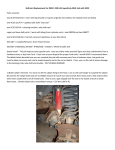
O2 Sensor Module Kit User’s Manual D000025 Rev D March 2012 Drivven, Inc. • 12001 Network Blvd.,Bldg.E, Suite 110 • San Antonio, Texas 78249 • USA Phone : 210.248.9308 Web : www.drivven.com , E-mail : [email protected] Drivven, Inc. O2 Sensor Module Kit Contents Introduction ......................................................................................................................... 3 Pinout .................................................................................................................................. 4 Hardware ............................................................................................................................. 5 Powering the Module .......................................................................................................... 6 Platform Compatibility ....................................................................................................... 7 Bosch LSU 4.2 Wide-Band Oxygen Sensor Controllers .................................................... 9 Narrow-Band Oxygen Sensor Inputs ................................................................................ 12 Module Connector Parts and Tools................................................................................... 17 Software Installer .............................................................................................................. 18 Creating a LabVIEW Project ............................................................................................ 20 Sub VI Documentation ..................................................................................................... 22 Warning About FPGA I/O Node Wiring .......................................................................... 29 Compliance and Certifications .......................................................................................... 30 Physical Specifications and Characteristics ...................................................................... 31 © Drivven, Inc. 2009 • O2 Sensor Module Kit User’s Manual • D000025 • Rev D 2 Drivven, Inc. O2 Sensor Module Kit Introduction The Drivven cRIO O2 Sensor Module Kit provides an interface for multiple wide-band and narrow band exhaust oxygen sensors. Features: 2 Ch. Bosch LSU 4.2 wide-band sensor controller o Fuse-protected heater control circuits (serviceable) 4 Ch. Narrow-band sensor input (differential) All channel readings updated at 1kHz LabVIEW FPGA and RT VIs included for quick integration with application © Drivven, Inc. 2009 • O2 Sensor Module Kit User’s Manual • D000025 • Rev D 3 Drivven, Inc. O2 Sensor Module Kit Pinout © Drivven, Inc. 2009 • O2 Sensor Module Kit User’s Manual • D000025 • Rev D 4 Drivven, Inc. O2 Sensor Module Kit Hardware This module provides controllers for Bosch LSU 4.2 wide-band oxygen sensors and inputs for zirconium-dioxide-element narrow-band oxygen sensors (most common). A properly strain relieved DB-37 connector (not included) is used to interface to the module. National Instruments provides the "cRIO-9933 37-pin Conn. Kit, screw term conn. and DSUB shell" which is compatible with this module. However, any DB-37 connector system may be used. Drivven recommends the following DB-37 connector parts and tools available from several electronics parts distributors (Allied, Mouser, Digikey, etc.). Table 1. Connector parts list Description AMP HDP-20 Series 109 37P Receptacle Housing AMP HDP-20 Series 109 Crimp Socket Contact Norcomp D-Sub Connector Hood, 37P 45 Degree AMP D-Sub Insert/Extract Tool Paladin D-Sub 4-Indent Crimp Tool 26-20 AWG Mfr.’s Part # 1757820-4 205090-1 971-037-020R121 91067-2 1440 © Drivven, Inc. 2009 • O2 Sensor Module Kit User’s Manual • D000025 • Rev D 5 Drivven, Inc. O2 Sensor Module Kit Powering the Module The O2 Sensor Module requires power from two different sources. One source is from the CompactRIO backplane male high density D-Sub 15-pin (HD15) connector which mates with the module’s female HD15 connector. This power source provides a regulated 5 volts and ground to various digital logic functions within the module. The CompactRIO 5V source is active whenever the CompactRIO or R-Series Expansion Chassis is properly powered. The module should only be powered at the HD15 connector by plugging it into a CompactRIO or R-Series Expansion Chassis. The module’s HD15 connector should not be connected to any other device. Another required power connection is at the external DB-37 connector. The terminals are labeled BATT (10) and GND (29). Typical power sources will be from automotive 12V battery systems. However, the module can accept power from a range of 6V to 17V. With no sensors connected, the module requires up to 100mA from the external supply. However, the external supply must be capable of powering the heaters within the sensors connected to the module. Therefore a battery or power supply capable of 12A may be necessary under full load. Each sensor heater requires approximately 2A during the first 30 seconds of operation and approximately 1A thereafter. UEGO sensor heaters are powered and controlled directly from the O2 Sensor Module. EGO sensor heaters are powered externally and do not require heater control by the module. This module requires both external power and power from the CompactRIO backplane. The module is designed in such a way that the high current path is directed through the BATT and GND terminals on the front of the module and not through the HD15 backplane connector. The module will not be recognized by software without both power supplies active. Warning: The external battery supply input terminals are not reverse voltage polarity protected. Connecting power to the module in reverse polarity will damage the module. This event is not covered by the warranty. Please refer to the DrivvenReverseBatteryNotice.pdf document (available on the website) for a recommended solution for protecting a system from reverse battery polarity. © Drivven, Inc. 2009 • O2 Sensor Module Kit User’s Manual • D000025 • Rev D 6 Drivven, Inc. O2 Sensor Module Kit Platform Compatibility CompactRIO modules from Drivven are compatible within two different platforms from National Instruments. One platform is CompactRIO, consisting of a CompactRIO controller and CompactRIO chassis as shown in Figure 1a below. Figure 1a. CompactRIO platform compatible with Drivven CompactRIO modules. The other platform is National Instruments PXI which consists of any National Instruments PXI chassis along with a PXI RT controller and PXI-78xxR R-Series FPGA card. An R-Series expansion chassis must be connected to the PXI FPGA card via a SHC68-68-RDIO cable. The CompactRIO modules insert into the R-Series expansion chassis. This platform is shown in Figure 1b below. Figure 1b. PXI platform compatible with Drivven CompactRIO modules. Drivven CompactRIO modules are not compatible with the National Instruments CompactDAQ chassis. Drivven CompactRIO modules REQUIRE one of the hardware support systems described above in order to function. The modules may not be used by themselves and/or interfaced to third party devices at the backplane HD15 connector. These efforts will not be supported by Drivven or National Instruments. You can use Drivven C Series modules with NI cRIO-911x, NI cRIO-907x, and NI R Series Expansion systems under the following conditions. –Leave one empty chassis slot between Drivven and NI modules. © Drivven, Inc. 2009 • O2 Sensor Module Kit User’s Manual • D000025 • Rev D 7 Drivven, Inc. O2 Sensor Module Kit –Maintain an ambient system operating temperature of 0 to 45 °C. –Typical specifications of NI modules may not apply when used in a system with Drivven modules. –Warranted specifications are guaranteed for all NI modules except thermocouple modules when used in a system with Drivven modules. –The NI 9214 is recommended for thermocouple measurements in cRIO systems using Drivven modules. –Scan Interface mode, auto-detection, and ID mode are not supported for Drivven modules. © Drivven, Inc. 2009 • O2 Sensor Module Kit User’s Manual • D000025 • Rev D 8 Drivven, Inc. O2 Sensor Module Kit Bosch LSU 4.2 Wide-Band Oxygen Sensor Controllers The O2 Sensor Module Kit provides two identical Bosch LSU 4.2 sensor controllers. They are called controllers because there is much more involved than just sensing a voltage signal from the sensor. In general, the module controls the current (pump current, Ip) to the sensor element so as to maintain a fixed voltage reference across the element. The exhaust oxygen content, and therefore the air-fuel mass ratio, is proportional to Ip. The temperature of the sensor element is also critical in order to obtain a good exhaust oxygen measurement. The module controls the sensor element temperature to 750 degrees Celsius. The detailed description and internal operation of a wide-band oxygen sensor and its control is beyond the scope of this document. The purpose of this document is to instruct the user on how to properly connect the module to the Bosch LSU 4.2 sensor and operate the provided VIs to interface with the module. The Drivven O2 Sensor Module Kit wide-band sensor controllers are only intended to be used with the widely available production Bosch LSU 4.2 (or equivalent) sensors. Another common wide-band sensor is also available from NTK, but is not compatible with this module kit. Drivven makes available a Bosch LSU 4.2 17014 (or equivalent) sensor package which includes the following: ** Bosch LSU 4.2 17014 (or equivalent) Sensor ** 10 foot cable with Bosch LSU 4.2 mating connector (un-terminated wires on opposite end) ** Sensor bung Drivven’s Bosch LSU 4.2 17014 (or equivalent) sensor package is listed on the www.drivven.com website under part number D000027, along with the O2 Sensor Module Kit. Sources for Bosch LSU 4.2 Sensors, Connectors, Cables, etc. Bosch LSU 4.2 sensor part numbers (2X3 pin “D” connector): 0 258 007 057 (Bosch universal part number) 17014 (Bosch USA part number) Standard Motor Products cross reference: SG897 Airtex cross reference: 5S4265 ACDelco cross reference: 2133894 Volkswagen OEM part number for Bosch LSU 4.2 021-906-262-B Volkswagen OEM part number for mating connector housing: 1J0973733 Available from www.1stvwparts.com Volkswagen OEM part number for wire leads with pin sockets on each end (3 required): 000979133A Available from www.1stvwparts.com Volkswagen OEM part number for wire grommets (6 optional): 357972741A Available from www.1stvwparts.com © Drivven, Inc. 2009 • O2 Sensor Module Kit User’s Manual • D000025 • Rev D 9 Drivven, Inc. O2 Sensor Module Kit The Bosch LSU 4.2 sensor is used in a variety of vehicles (Volkswagen Golf, Jetta, Beetle, etc), but can often be found when performing a search on an auto parts website under “Volkswagen 2002 Golf GTI 1.8L Turbo Upstream Sensor”. For cabling, Drivven recommends using 6-conductor, 22 AWG cable having stranded, tinned copper wires and proper shielding. One example of such cable is Belden part number 9942 distributed by Allied Electronics. The above suggested cable has a standard wire color coding according to: No. 1 – Black No. 2 – White No. 3 – Red No. 4 – Green No. 5 – Brown No. 6 – Blue This color coding will be assumed for the wiring description below. For oxygen sensor port bungs, Drivven suggests searching the Summit Racing website with the following phrase: weld in oxygen sensor bungs Several options for oxygen sensor bungs will be presented. However, they will all have the same standard threads. Adding the Sensor Cable to the Module Connector The color coding of the Bosch LSU 4.2 wide-band sensor wires differ from the available color coding in a 6-conductor cable. The following table 2 and figure 2 shows the proper connection from the LSU 4.2 sensor connector, to the intermediate cable, to the Drivven module. The Drivven module label provides wire color information next to its DB-37 pin names according to the standard Bosch LSU 4.2 sensor wire coloring, not according to any intermediate wiring. Note that sensor pin 2 does not actually have a green wire from the sensor to the sensor-connector. There is a calibration resistor feeding this connector pin. The color code of green has been the standard color for the calibration sensor location. © Drivven, Inc. 2009 • O2 Sensor Module Kit User’s Manual • D000025 • Rev D 10 Drivven, Inc. Module Pin Label UN (B) IA (GN) HTR+ (GY) HTR- (W) VM (Y) IP (R) O2 Sensor Module Kit Table 2. Bosch LSU 4.2 Sensor Connection Intermediate Cable LSU 4.2 Wire Color LSU 4.2 Pin Number Wire Color Black Black 1 Green N/A 2 Brown Grey 3 White White 4 Blue Yellow 5 Red Red 6 Figure 2. Bosch LSU 4.2 Sensor Wiring If you choose to use a Bosch LSU 4.2 sensor that has a connector other than the 2X3 D-shape connector (such as the 6066 model), then you must follow the standard LSU 4.2 wire color code and not the LSU 4.2 7057 pin number association from Table 2. A single fuse is located in the module circuit which feeds battery voltage to both sensor heaters. The status of the fuse is provided in software by the UEGOFuseStatus enumerated integer within the UEGO Diagnostics cluster of the RT VI. Replacement internal fuse: 2 Littelfuse R451 Series Nano 7.0 Amp: 0451007.MRL Digikey Part number: F2589CT-ND © Drivven, Inc. 2009 • O2 Sensor Module Kit User’s Manual • D000025 • Rev D 11 Drivven, Inc. O2 Sensor Module Kit Narrow-Band Oxygen Sensor Inputs The O2 Sensor Module Kit provides four identical zirconium-dioxide-element, narrow-band (switching), oxygen sensor inputs. The detailed description and internal operation of a narrow-band oxygen sensor is beyond the scope of this document. The purpose of this document is to instruct the user on how to properly connect the module to a variety of zirconium-dioxide-element oxygen sensors and operate the provided VIs to interface with the module. There are a number of different types of standard zirconium-oxide-element oxygen sensors which the Drivven O2 Sensor Module Kit supports. From here we will refer to these sensors as Exhaust Gas Oxygen (EGO) sensors. These sensors may also be referred to in other literature as lambda sensors. This document will discuss EGO sensor wires in terms of “universal” EGO sensors which have a standardized wire color code. OEM-specific EGO sensors may have a different wire color code and should be further researched to determine what function is associated with each wire. Four different EGO sensors are discussed below, however, Drivven recommends the use of the 4-wire, heated, universal EGO sensor. 1-Wire Universal EGO Sensors 1-Wire EGO sensors have a single black wire which provides the lambda signal and is referenced to the sensor body or engine/exhaust system ground. The black wire must be connected to the EGO+ pin of the module DB-37 connector. Also, a wire jumper must be connected from one of the module EGO- pins for the associated EGO channel to one of the module GND pins. This is shown below in figure 3. Figure 3. 1-Wire EGO Sensor Connection © Drivven, Inc. 2009 • O2 Sensor Module Kit User’s Manual • D000025 • Rev D 12 Drivven, Inc. O2 Sensor Module Kit 2-Wire Universal EGO Sensors 2-Wire EGO sensors have black and gray wires which provide a differential lambda signal. The black wire must be connected to the EGO+ pin of the module DB-37 connector. The gray wire must be connected to one of the EGO- pins for the associated channel of the module DB-37 connector. Also, a wire jumper must be connected from the other EGO- pin for the associated EGO channel to one of the module GND pins. This is shown below in figure 4. If using a non-universal EGO sensor with different wire colorings, then it may require a trial and error process to get the wiring polarity correct. The sensor will not be damaged if the wire polarity is reversed, however, the sensor will not provide a correct reading and will likely show up as a cold sensor in the software. Figure 4. 2-Wire EGO Sensor Connection © Drivven, Inc. 2009 • O2 Sensor Module Kit User’s Manual • D000025 • Rev D 13 Drivven, Inc. O2 Sensor Module Kit 3-Wire Universal Heated EGO Sensors 3-Wire EGO sensors have a black wire and two white wires. The black wire provides the lambda signal and is referenced to the sensor body or engine/exhaust system ground. The black wire must be connected to the EGO+ pin of the module DB-37 connector. Also, a wire jumper must be connected from one of the module EGO- pins for the associated EGO channel to one of the module GND pins. The two white wires connect to a resistive heater element inside the EGO sensor. These wires should be connected to 12 volts and ground. The O2 sensor module does not provide connections for these wires. They must be connected to a power source externally. This is shown below in figure 5. The user may wish to power them via a relay which is energized with the main ignition switch and optionally insert a 3 amp fuse per sensor. If using a nonuniversal EGO sensor with different wire colorings, then you must first identify the two wires which are connected to the heater element. This can be determined by testing for approximately 5 ohms across two of the wires. The remaining wire is the lambda signal wire. Figure 5. 3-Wire EGO Sensor Connection © Drivven, Inc. 2009 • O2 Sensor Module Kit User’s Manual • D000025 • Rev D 14 Drivven, Inc. O2 Sensor Module Kit 4-Wire Universal EGO Sensors 4-Wire EGO sensors have a black and gray wire and two white wires. The black and gray wires provide a differential lambda signal. The black wire must be connected to the EGO+ pin of the module DB-37 connector. The gray wire must be connected to one of the EGO- pins for the associated channel of the module DB-37 connector. Also, a wire jumper must be connected from the other EGO- pin for the associated EGO channel to one of the module GND pins. The two white wires connect to a resistive heater element inside the EGO sensor. These wires should be connected to 12 volts and ground. The O2 sensor module does not provide connections for these wires. They must be connected to a power source externally. This is shown below in figure 6. The user may wish to power them via a relay which is energized with the main ignition switch and optionally insert a 3 amp fuse per sensor. If using a non-universal EGO sensor with different wire colorings, then you must first identify the two wires which are connected to the heater element. This can be determined by testing for approximately 5 ohms across two of the wires. The remaining two wires are the differential lambda signal wires. It may require a trial and error process to get the lambda signal wiring polarity correct. The sensor will not be damaged if the wire polarity is reversed, however, the sensor will not provide a correct reading and will likely show up as a cold sensor in the software. Figure 6. 4-Wire EGO Sensor Connection © Drivven, Inc. 2009 • O2 Sensor Module Kit User’s Manual • D000025 • Rev D 15 Drivven, Inc. O2 Sensor Module Kit Sources for EGO Sensors and Connectors There are many compatible EGO sensors available, but Drivven will recommend one 4-wire sensor and connector system. Bosch part number for 4-wire premium oxygen sensor: 15717 An internet search on this part number will show several listings of this sensor for sale for approximately $45-$55. The sensor is commonly found on Ford vehicles and will have a round 4pin connector attached as shown in figure 7 below. Figure 7. Bosch 15717 sensor A mating connector is available from www.rockauto.com under Standard Auto Parts part number S631, shown below in figure 8. Figure 8. Mating connector (S631) for Bosch 15717 sensor Drivven makes available a Bosch 15717 4-wire sensor package which includes the following: ** Bosch 15717 4-Wire Sensor ** 10 foot cable with mating Bosch 15717 4-wire sensor connector (loose wires on opposite end) ** Sensor bung Drivven’s Bosch 15717 4-wire sensor package is listed on the www.drivven.com website under part number D000028, along with the O2 Sensor Module Kit. © Drivven, Inc. 2009 • O2 Sensor Module Kit User’s Manual • D000025 • Rev D 16 Drivven, Inc. O2 Sensor Module Kit Module Connector Parts and Tools Please refer to Table 1. © Drivven, Inc. 2009 • O2 Sensor Module Kit User’s Manual • D000025 • Rev D 17 Drivven, Inc. O2 Sensor Module Kit Software Installer The O2 Sensor Module Kit is provided with an installer package which may be downloaded from Drivven’s Sharepoint website after obtaining login access from Drivven. User’s may go to http://portal.drivven.com/SoftwareDownload and enter the provided username and password to gain access to the specific product installer packages which have been purchased. The installer packages are executables which should be run on the intended development computer, having LabVIEW development tools installed. After installing the package, a “Start->Programs->Drivven>ProductRelease” menu item will be added to the desktop. The specific product will have an example LabVIEW project appear under the “Examples” menu and the user manual will appear under the “Manuals” menu. User’s may copy and open the example project to experiment with the module or use as a starting point for a new application. All software files, example projects and documentation are installed to: C:\Program Files\National Instruments\LabVIEW X.X\vi.lib\addons\DrivvenProductRelease\. When working with block diagrams, user’s will notice a “Drivven” function palette added to the standard LabVIEW palette, specific for the RT or FPGA target. VIs for a specific Drivven product will be categorized according to product name. Also, some Drivven products will install RT and FPGA VIs under a “General” function palette which is intended to be used across multiple products. Requirements The Drivven VIs require: LabVIEW 8.5 Full Development or later LabVIEW RT Module 8.5 or later LabVIEW FPGA Module 8.5 or later NI-RIO 2.4 or later The O2 Sensor Module Kit is provided with both a LabVIEW FPGA VI for interfacing directly to the module and a LabVIEW RT VI for interfacing with the FPGA VI and managing and reporting sensor results. Figure 9 shows the icon which represents FPGA uego_revx.vi. Figure 9. FPGA VI icon with leads. Figure 10 shows the icon which represents uego_rt_revx.vi. Figure 10. RT VI icon with leads. The FPGA VI must be placed within a Single Cycle Loop (SCL) of a LabVIEW FPGA block diagram. The SCL must execute at the default clock rate of 40 MHz. © Drivven, Inc. 2009 • O2 Sensor Module Kit User’s Manual • D000025 • Rev D 18 Drivven, Inc. O2 Sensor Module Kit The FPGA VI requires a pre-synthesized netlist file having a matching name and an extension of .ngc. The netlist file must be located in the same directory as the matching VI. The installer will place this file in the LabVIEW addons directory along with the FPGA VI. © Drivven, Inc. 2009 • O2 Sensor Module Kit User’s Manual • D000025 • Rev D 19 Drivven, Inc. O2 Sensor Module Kit Creating a LabVIEW Project Drivven recommends working from the provided example application as a starting point for learning the use of the Drivven software blocks. However, the following section describes starting a LabVIEW project from scratch and adding a Drivven module. 1.) Install the Drivven software by running the installer executable and accepting the software license agreement. 2.) Restart LabVIEW, if previously running, and create a new LabVIEW project. 3.) Give the new project a name by clicking the “Save Project” button on the project toolbar. 4.) Right click on the highest item in the project hierarchy (“Project:…”) and navigate to “New->Targets and Devices…” 5.) Within the “Add Targets and Devices…” dialog, select the appropriate radio button, depending on whether you already have an existing powered and configured RT target on the network or if you are adding a new RT target which is not present yet on the network. a. Existing Target or Device i. Expand the appropriate category in the “Targets and Devices” list to see the discovered targets in that category. ii. Double-click the desired target to add it to your project. b. New Target or Device i. Expand the appropriate category in the “Targets and Devices” list to see all possible targets within that category. ii. Double-click the desired target to add it to your project. 6.) If the new RT target is not currently on the network, right-click on the RT target within the project and open the properties dialog to set the IP address or DNS name if necessary. 7.) Right-click on the RT target within the project and navigate to “New->Targets and Devices…” 8.) Within the “Add Targets and Devices…” dialog, select the appropriate radio button, depending on whether you already have an existing FPGA target connected to an existing RT target or if you are adding a new FPGA target which is not present yet. a. Existing Target or Device i. Expand the appropriate category in the “Targets and Devices” list to see the discovered FPGA targets in that category. ii. Double-click the desired target to add it to your project. b. New Target or Device i. Expand the appropriate category in the “Targets and Devices” list to see all possible targets within that category ii. Double-click the desired target to add it to your project. 9.) If the new FPGA target was not currently in the system, right-click on the FPGA target within the project and open the properties dialog to set the resource name if necessary. The resource name can be found from MAX when connected to the actual remote system. 10.) If the FPGA target is a PXI or PCI card, then an R Series expansion chassis must be added under the FPGA target. This is done by right-clicking on the FPGA target and navigating to “New->R Series Expansion Chassis”. Within the following dialog, select the appropriate FPGA connector to which the chassis will be connected. A unique name for the chassis may also be specified. 11.) Right click on the R-Series expansion chassis or cRIO FPGA target chassis and navigate to “New->C Series Modules…” 12.) Select the “New Target or Device” radio button and double-click on the “C Series Module” in the “Targets and Devices” list. In the following dialog, select the desired Drivven module at the bottom of the “Module Type” list. The Drivven modules will be appended there if any Drivven module software has been installed. Select the appropriate module © Drivven, Inc. 2009 • O2 Sensor Module Kit User’s Manual • D000025 • Rev D 20 Drivven, Inc. O2 Sensor Module Kit location. Finally, specify an appropriate name for the module, which will later appear in the FPGA I/O nodes in the FPGA block diagram. Having meaningful module names is important for preventing coding mistakes. 13.) After adding a module to the project, a folder will automatically be added to the project having the same module name given in the module configuration dialog. The folder will contain the FPGA I/O pins for the module slot. These I/O pins can be selected in the block diagram when connecting the module VI PinInput and PinOutput clusters to FPGA I/O nodes. The example application, discussed below, should be consulted for further details about connecting the PinInput and PinOutput clusters to FPGA I/O nodes. Within the example projects, notice the FPGA I/O node elements having module name prefixes. 14.) Some Drivven modules can be automatically recognized by LabVIEW when adding cRIO modules to the project. However, Drivven does not recommend using this feature because the module names, which are automatically assigned, are not meaningful (Mod1, Mod2, etc) and can lead to coding mistakes when wiring the Drivven FPGA VIs to the I/O nodes. Adding the modules to the project manually, as described above, is still the recommended method. © Drivven, Inc. 2009 • O2 Sensor Module Kit User’s Manual • D000025 • Rev D 21 Drivven, Inc. O2 Sensor Module Kit Sub VI Documentation uego_revd.vi This VI is for interfacing directly with the Drivven O2 Sensor module and for providing a control interface to the LabVIEW RT level. The FPGA VI must be placed within a Single Cycle Loop (SCL) of a LabVIEW FPGA block diagram. The SCL must execute at the default clock rate of 40 MHz. The FPGA VI requires a pre-synthesized netlist file having a matching name and an extension of .ngc. The netlist file must be located in the same directory as the matching VI. The installer will place this file in the LabVIEW addons directory along with the FPGA VI. The PinInput and PinOutput clusters are wired to LabVIEW FPGA I/O nodes which are configured for a cRIO controller chassis or a cRIO R-Series expansion chassis. Refer to the LabVIEW FPGA documentation for details about creating and configuring FPGA I/O nodes. Connector Pane Controls and Indicators UEGOPinInput These boolean controls must be connected to their corresponding FPGA I/O Node input item. UEGOControl The UEGOControl Cluster should be terminated with a control cluster and made available as a complete cluster for interfacing to the RT VI. No FPGA code interface is required with any of the members of this cluster. UEGOPinOutput The boolean indicator named IDSelectEn must be connected to a Set Output Enable method of an FPGA I/O Method Node. The boolean indicator named IDSelectOut must be connected to a Set Output Data method of an FPGA I/O Method Node. The remaining boolean indicators must be connected to their corresponding FPGA I/O Node output item. UEGOData The UEGOData Cluster should be terminated with an indicator cluster and made available as a complete cluster for interfacing to the RT VI. No FPGA code interface is required with any of the members of this cluster. © Drivven, Inc. 2009 • O2 Sensor Module Kit User’s Manual • D000025 • Rev D 22 Drivven, Inc. O2 Sensor Module Kit uego_rt_revd.vi The uego_rt_revx.vi (RT VI) must be placed within a while loop or timed loop and executed at a minimum rate of 10 Hz. This is the minimum rate to maintain the watchdog within the module. A rate of 50-200Hz is recommended for controlling fuel based on Lambda feedback. A reference must be opened to a LabVIEW FPGA application which implements the uego_revx.vi. Also, FPGA read/write register functions must be placed within the RT loop to gain access to the UEGOControl and UEGOData clusters of the FPGA uego_revx.vi. Connector Pane Controls and Indicators UEGOCalibration Included within the O2 Sensor Module Kit software bundle is a VI named uego_calibration.vi. That sub VI has an output named UEGOCalibration and may optionally be wired to this input cluster to provide a custom UEGO calibration. Internally, this cluster input has a default calibration for gasoline and diesel. To see the default calibration, create a constant or control from this terminal. The uego_calibration.vi contains a simple case structure which selects the constant calibration arrays for Ip versus Lambda. By default, there are two cases established for Fuel Selection of Gasoline and Diesel. These calibrations are identical and are derived from the datasheet for the Bosch LSU 4.2 sensor. The user has the ability to create additional calibration cases for any other fuel type. The calibration procedure is simple. First, adjust the exhaust gas mixture to achieve a particular Ip reading from the UEGO Sensor Results cluster. This Ip value calibration point would be entered into the constant Ip array. Then take a lambda reading from a secondary calibrated sensor and enter this lambda value in the constant lambda array for the corresponding Ip array entry. Ip values in the constant Ip array must be increasing. The uego_rt_revx.vi uses these two constant arrays within an interpolation lookup table algorithm to calculate the lambda value based on the sensed Ip value. Phi and AFRatio are then derived from lambda. Stoich A/F Ratio The stoichiometric air-fuel ratio of the calibrated fuel-type. IpArray (mA) Array of increasing sensor pump-current values (Ip) corresponding to a Lambda value. LambdaArray Array of Lambda values corresponding to a sensor pump-current (Ip). UEGOModuleEnable If the RT VI detects a powered O2 sensor module in the correct slot and UEGOModuleEnable is TRUE, then the RT VI begins initializing the wide-band sensors, bringing them up to temperature, and updating sensor results in the UEGO Sensor Results cluster. If the module is present but no sensors are connected, then the RT VI will time out (30 seconds) with its attempt to bring the sensors up to temperature and discontinue heater control. UEGOModuleEnable must be set to FALSE and back to TRUE in order to make another attempt at sensor control. It is important that disconnected wide-band sensors are NOT connected while UEGOModuleEnable is TRUE. It is possible to damage the sensor element of a cold sensor if the sensor © Drivven, Inc. 2009 • O2 Sensor Module Kit User’s Manual • D000025 • Rev D 23 Drivven, Inc. O2 Sensor Module Kit connection is made while the UEGOModuleEnable is TRUE and the heater duty cycle is approaching 100%. Sensors should already be connected when UEGOModuleEnable is set to TRUE so that the temperature is brought up according to a profile specified by Bosch. UEGO Back Pressure (bar) The sensed air/fuel mass ratio results are dependent on exhaust system pressure. Many engine systems will have exhaust systems which are very near atmospheric pressure. In this case, this control may be left disconnected or set to a constant value of 1.013 bar. However, if exhaust system pressure is expected to depart from atmospheric pressure at the location of the sensor, then the pressure should be wired to this control. UEGOData (From FPGA) The UEGOData Cluster control should be wired from the UEGOData indicator from the FPGA VI. SensorEnable Allows each individual sensor interface to be enabled or disabled. UEGO Diagnostics A collection of diagnostic parameters related to the module, O2 sensor element, O2 sensor heater circuit and module fuse. ModulePresent Indicates that the module is plugged in to the proper slot, externally powered and recognized by the FPGA VI. Software may not recognize the module if the software and hardware revisions do not match. UEGO1SensorFault NO FAULT: No faults exist with the sensor signal wires. SHORT TO GND OR BATT: A short to ground or battery is present on one of the sensor signal wires. UEGO2SensorFault NO FAULT: No faults exist with the sensor signal wires. SHORT TO GND OR BATT: A short to ground or battery is present on one of the sensor signal wires. UEGO1HeaterFault NO FAULT: No faults exist with the sensor heater wires. SHORT TO GROUND: A short to ground is present on one of the sensor heater wires. OPEN CIRCUIT: An open circuit is present on one of the sensor heater wires. SHORT TO BATTERY: A short to battery is present on one of the sensor heater wires. UEGO2HeaterFault NO FAULT: No faults exist with the sensor heater wires. SHORT TO GROUND: A short to ground is present on one of the sensor heater wires. OPEN CIRCUIT: An open circuit is present on one of the sensor heater wires. SHORT TO BATTERY: A short to battery is present on one of the sensor heater © Drivven, Inc. 2009 • O2 Sensor Module Kit User’s Manual • D000025 • Rev D 24 Drivven, Inc. O2 Sensor Module Kit wires. UEGOFuseStatus A single fuse is located in the module circuit which feeds battery voltage to both sensor heaters. FUSE OK: The heater circuit fuse is OK. FUSE BLOWN: The heater circuit fuse is blown. Battery (V) Battery voltage sensed internal to the module while enabled. UEGO Sensor Results Cluster of parameters indicating the measured O2 in the exhaust gas. UEGO1Lambda The actual air/fuel mass ratio divided by the stoichiometric air/fuel mass ratio. Lambda is equivalent to 1/Phi. UEGO1Phi The actual fuel/air mass ratio divided by the stoichiometric fuel/air mass ratio. Phi is equivalent to 1/Lambda. UEGO1AFRatio The actual air/fuel mass ratio. UEGO1Ip (mA) The pump current required for maintaining a reference voltage of 450 millivolts across the wide-band sensor element. This is also the current required for maintaining a stoichiometric gas mixture within the sensor element. UEGO2Lambda The actual air/fuel mass ratio divided by the stoichiometric air/fuel mass ratio. Lambda is equivalent to 1/Phi. UEGO2Phi The actual fuel/air mass ratio divided by the stoichiometric fuel/air mass ratio. Phi is equivalent to 1/Lambda. UEGO2AFRatio The actual air/fuel mass ratio. UEGO2Ip (mA) The pump current required for maintaining a reference voltage of 450 millivolts across the wide-band sensor element. This is also the current required for maintaining a stoichiometric gas mixture within the sensor element. EGO Sensor Results Cluster of EGO sensor results. EGO1Status COLD SENSOR: When a narrow-band sensor is cold, the sensor input circuit will report a voltage of approximately 450 millivolts and will not fluctuate with rich and lean exhaust mixtures. This enumeration is reported when the sensor value remains in the range of 400 to 500 millivolts for a period of 1 second. FOULED SENSOR: When a narrow-band sensor is fouled or aged, the sensor value will transition from rich to lean and from lean to rich much slower than that of a normally operating sensor. This enumeration is reported when the sensor value takes longer than 1 second to transition from below 300 millivolts to above 600 millivolts or vice versa. RICH: The sensor is sourcing a voltage of greater than 600 millivolts. LEAN: The sensor is sourcing a voltage of less than 300 millivolts. © Drivven, Inc. 2009 • O2 Sensor Module Kit User’s Manual • D000025 • Rev D 25 Drivven, Inc. O2 Sensor Module Kit EGO2Status COLD SENSOR: When a narrow-band sensor is cold, the sensor input circuit will report a voltage of approximately 450 millivolts and will not fluctuate with rich and lean exhaust mixtures. This enumeration is reported when the sensor value remains in the range of 400 to 500 millivolts for a period of 1 second. FOULED SENSOR: When a narrow-band sensor is fouled or aged, the sensor value will transition from rich to lean and from lean to rich much slower than that of a normally operating sensor. This enumeration is reported when the sensor value takes longer than 1 second to transition from below 300 millivolts to above 600 millivolts or vice versa. RICH: The sensor is sourcing a voltage of greater than 600 millivolts. LEAN: The sensor is sourcing a voltage of less than 300 millivolts. EGO3Status COLD SENSOR: When a narrow-band sensor is cold, the sensor input circuit will report a voltage of approximately 450 millivolts and will not fluctuate with rich and lean exhaust mixtures. This enumeration is reported when the sensor value remains in the range of 400 to 500 millivolts for a period of 1 second. FOULED SENSOR: When a narrow-band sensor is fouled or aged, the sensor value will transition from rich to lean and from lean to rich much slower than that of a normally operating sensor. This enumeration is reported when the sensor value takes longer than 1 second to transition from below 300 millivolts to above 600 millivolts or vice versa. RICH: The sensor is sourcing a voltage of greater than 600 millivolts. LEAN: The sensor is sourcing a voltage of less than 300 millivolts. EGO4Status COLD SENSOR: When a narrow-band sensor is cold, the sensor input circuit will report a voltage of approximately 450 millivolts and will not fluctuate with rich and lean exhaust mixtures. This enumeration is reported when the sensor value remains in the range of 400 to 500 millivolts for a period of 1 second. FOULED SENSOR: When a narrow-band sensor is fouled or aged, the sensor value will transition from rich to lean and from lean to rich much slower than that of a normally operating sensor. This enumeration is reported when the sensor value takes longer than 1 second to transition from below 300 millivolts to above 600 millivolts or vice versa. RICH: The sensor is sourcing a voltage of greater than 600 millivolts. LEAN: The sensor is sourcing a voltage of less than 300 millivolts. EGO1Sensor (V) The voltage being sourced by the EGO sensor. EGO2Sensor (V) The voltage being sourced by the EGO sensor. EGO3Sensor (V) The voltage being sourced by the EGO sensor. EGO4Sensor (V) The voltage being sourced by the EGO sensor. © Drivven, Inc. 2009 • O2 Sensor Module Kit User’s Manual • D000025 • Rev D 26 Drivven, Inc. O2 Sensor Module Kit UEGO Temperature (C) Cluster of indicators showing the heater temperature and valid operating temperature range. UEGO1Temp (C) The controlled temperature, in degrees Celsius, of the wideband sensor element. UEGO2Temp (C) The controlled temperature, in degrees Celsius, of the wideband sensor element. UEGO1Hot The target sensor temperature is 750 degrees Celcius. When TRUE, the wide-band sensor element temperature has entered a controlled temperature range above 730 degrees Celsius and the air/fuel ratio and related values are valid. When FALSE, the air/fuel ratio and related values are not valid. UEGOXHot will transition from TRUE to FALSE when going below 700 degrees Celsius. UEGO2Hot The target sensor temperature is 750 degrees Celcius. When TRUE, the wide-band sensor element temperature has entered a controlled temperature range above 730 degrees Celsius and the air/fuel ratio and related values are valid. When FALSE, the air/fuel ratio and related values are not valid. UEGOXHot will transition from TRUE to FALSE when going below 700 degrees Celsius. UEGOControl (To FPGA) The UEGOControl Cluster should be wired to the UEGOControl cluster of the FPGA VI. UEGO Heater Duty Cycle (%) The heater duty cycle values are brought out for debug purposes only. © Drivven, Inc. 2009 • O2 Sensor Module Kit User’s Manual • D000025 • Rev D 27 Drivven, Inc. O2 Sensor Module Kit uego_calibration.vi This sub VI has an output named UEGOCalibration and may optionally be wired to the UEGOCalibration input cluster of the uego_rt_revx.vi to provide a custom UEGO calibration. Internally, the uego_rt_revx.vi cluster input has a default calibration for gasoline and diesel. The uego_calibration.vi contains a simple case structure which selects the constant calibration arrays for Ip versus Lambda. By default, there are two cases established for Fuel Selection of Gasoline and Diesel. These calibrations are identical and are derived from the datasheet for the Bosch LSU 4.2 sensor. The user has the ability to create additional calibration cases for any other fuel type. The calibration procedure is simple. First, adjust the exhaust gas mixture to achieve a particular Ip reading from the UEGO Sensor Results cluster. This Ip value calibration point would be entered into the constant Ip array. Then take a lambda reading from a secondary calibrated sensor and enter this lambda value in the constant lambda array for the corresponding Ip array entry. Ip values in the constant Ip array must be increasing. The uego_rt_revx.vi uses these two constant arrays within an interpolation lookup table algorithm to calculate the lambda value based on the sensed Ip value. Phi and AFRatio are then derived from lambda. Fuel Selection Used to select a specific fuel tpye calibration. You may edit the items within this text Combo Box by right-clicking and selecting "Edit Items". UEGOCalibration The selected Lambda calibration which is output from this VI. Stoich A/F Ratio The stoichiometric air-fuel ratio of the calibrated fuel-type. IpArray (mA) Array of increasing sensor pump-current values (Ip) corresponding to a Lambda value. LambdaArray Array of Lambda values corresponding to a sensor pump-current (Ip). © Drivven, Inc. 2009 • O2 Sensor Module Kit User’s Manual • D000025 • Rev D 28 Drivven, Inc. O2 Sensor Module Kit Warning About FPGA I/O Node Wiring Great care should be taken to ensure that I/O nodes are wired to the correct PinInput and PinOutput clusters of the correct module VI. If wired incorrectly, then undefined behavior or rd module damage could result. LabVIEW FPGA does not yet provide a method for 3 party module vendors to hide the DIO pins behind module VIs and still be portable to various system configurations. Therefore, a double-check of the I/O node wiring is recommended. Two LabVIEW FPGA code snippets are shown below from an ADCombo implementation which illustrate this issue. Figure 11 shows the correct implementation of the FPGA I/O node block for the PinOutput cluster of the ADCombo. On the other hand, figure 12 shows a coding mistake that should be avoided. Notice the ADCombo output items where a Spark module output item is selected instead of the correct ADCombo module output item. This means that the Spark (DIO5) output is being driven by the ADCombo logic and will cause strange behavior of the spark module, or possible damage. Figure 11. Representative FPGA output node for ADCombo with correct output item selection. Figure 12. Representative FPGA output node for ADCombo with incorrect output item selection for DIO5. This will cause strange behavior or damage to the spark module. Applying meaningful names to the modules within the project can help identify these coding mistakes. © Drivven, Inc. 2009 • O2 Sensor Module Kit User’s Manual • D000025 • Rev D 29 Drivven, Inc. O2 Sensor Module Kit Compliance and Certifications Safety This product meets the requirements of the following standards of safety for electrical equipment for measurement, control, and laboratory use: IEC 61010-1, EN 61010-1 UL 61010-1, CSA 61010-1 Electromagnetic Compatibility This product meets the requirements of the following EMC standards for electrical equipment for measurement, control, and laboratory use: EN 61326-1 (IEC 61326-1): Class A emissions; Industrial immunity EN 55011 (CISPR 11): Group 1, Class A emissions AS/NZS CISPR 11: Group 1, Class A emissions FCC 47 CFR Part 15B: Class A emissions ICES-001: Class A emissions Caution: When operating this product, use shielded cables and accessories. CE Compliance This product meets the essential requirements of applicable European Directives as follows: 2006/95/EC; Low-Voltage Directive (safety) 2004/108/EC; Electromagnetic Compatibility Directive (EMC) Environmental Management NI is committed to designing and manufacturing products in an environmentally responsible manner. NI recognizes that eliminating certain hazardous substances from our products is beneficial to the environment and to NI customers. For additional environmental information, refer to the NI and the Environment Web page at ni.com/environment. This page contains the environmental regulations and directives with which NI complies, as well as other environmental information not included in this document. Waste Electrical and Electronic Equipment (WEEE) EU Customers At the end of the product life cycle, all products must be sent to a WEEE recycling center. For more information about WEEE recycling centers, National Instruments WEEE initiatives, and compliance with WEEE Directive 2002/96/EC on Waste Electrical and Electronic Equipment, visit ni.com/environment/weee. Battery Replacement and Disposal Battery Directive This device contains a long-life coin cell battery. If you need to replace it, use the Return Material Authorization (RMA) process or contact an authorized National Instruments service representative. For more information about compliance with the EU Battery Directive 2006/66/EC about Batteries and Accumulators and Waste Batteries and Accumulators, visit ni.com/environment/batterydirective. © Drivven, Inc. 2009 • O2 Sensor Module Kit User’s Manual • D000025 • Rev D 30 Drivven, Inc. O2 Sensor Module Kit Management Methods for Controlling Pollution Caused by Electronic Information Products Regulation (China RoHS) Chinese Customers National Instruments is in compliance with the Chinese policy on the Restriction of Hazardous Substances (RoHS) used in Electronic Information Products. For more information about the National Instruments China RoHS compliance, visit ni.com/environment/rohs_china. 电子信息产品污染控制管理办法( 中国RoHS) 中国客户 National Instruments符合中国电子信息产品中限制使用某些有害物质指令 (RoHS)。 关于National Instruments中国RoHS合规性信息,请登录 ni.com/environment/rohs_china。(For information about China RoHS compliance, go to ni.com/environment/rohs_china.) Ferrite Requirement for EMC Compliance Install a clamp-on ferrite bead onto the power supply cable and the signal cable. Power to the module must be off when adding ferrites. Ferrites must be connected to the power cable and to the signal cable as close to the module as possible. Placing the ferrite elsewhere on the cable noticeably impairs its effectiveness. Determine the clamp-on ferrite beads to install based on your application. Use the following ferrites or other similar ferrites: Power cable: Laird 28A0592-0A2 (2 total) Signal cable: Wurth Electronics 7427154 (2 total) Physical Specifications and Characteristics Weight: 170 grams Maximum Altitude: 2000 m Maximum Ambient Temperature: 60º C Operating Humidity: 10% to 90% RH, noncondensing Pollution Degree: 2 Ingress Protection: IP40 For Indoor Use Only If you need to clean the module, wipe it with a dry towel Safety Guidelines Caution: Do not operate this module in a manner not specified in these operating instructions. Product misuse can result in a hazard. You can compromise the safety protection built into the product if the product is damaged in any way. If the product is damaged, return it to National Instruments for repair. © Drivven, Inc. 2009 • O2 Sensor Module Kit User’s Manual • D000025 • Rev D 31