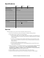
1
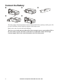
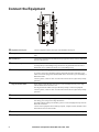
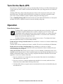
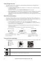
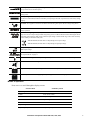
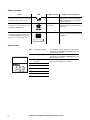
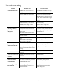
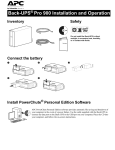
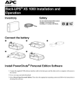
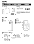
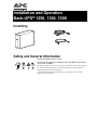
Installation and Operation Back-UPS® 1250, 1300, 1500 bu001a Inventory Safety and General Information This unit is intended for indoor use only. Do not operate this unit in direct sunlight, in contact with fluids, or where there is excessive dust or humidity. The battery typically lasts for two to five years. Environmental factors impact battery life. Elevated ambient temperatures, poor quality utility power, and frequent short duration discharges will shorten battery life. Connect the Back-UPS power cable directly into a wall outlet. Do not use surge protectors or extension cords. Connect the Battery bu055a bu057a bu059a bu060a bu058a The battery charges fully during the first 16 hours while the Back-UPS is operating on utility power. Do not expect full battery runtime capability during the initial charge period. Battery wear is not covered by the Limited Warranty. There are no serviceable parts in the Back-UPS. Do not attempt to open or repair the Back-UPS as this will void the warranty. The battery in this unit is not replaceable. Contact APC through customer support. Refer to the contact information at the end of this manual. 2 Installation and Operation Back-UPS 1250, 1300, 1500 PowerChute® Personal Edition Software Overview PowerChute Personal Edition Software allows you to use your computer to access additional power protection and management features of the Back-UPS. Using PowerChute, you can: • Preserve work in progress during a power outage by putting your computer into Hibernate mode. When the power returns, the computer will appear exactly as it did before the power outage. • Configure the Back-UPS management features, such as power-saving outlets, shutdown parameters, audible alarms, and more. • Monitor and view the status of the Back-UPS, including the estimated runtime, power consumption, power event history, and more. Available features will vary by Back-UPS model and operating system. If you choose not to install PowerChute, the Back-UPS will still provide backup power and power protection to connected equipment. However, you will only be able to configure a limited number of features using the display interface. Compatibility PowerChute is compatible with Windows operating systems only. For a detailed list of supported operating systems, go to www.apc.com, select Software & Firmware. For Mac operating systems, we recommend using the native shutdown application (within System Preferences) which recognizes your battery backup and allows you to configure shutdown of your system during power outages. To access this application, connect a USB cable from the Back-UPS DATA PORT (POWERCHUTE PORT) to a USB port on your computer, and see the documentation provided with your computer. Installation Connect the Back-UPS to a computer using a USB cable. Plug one end into the POWERCHUTE PORT on the rear panel of the Back-UPS and the other into a USB port on your computer. Insert the PowerChute CD into your computer and follow the on-screen instructions. If your Back-UPS did not come with a PowerChute CD, download the software from www.apc.com, select Software & Firmware. Installation and Operation Back-UPS 1250, 1300, 1500 3 bu056a Connect the Equipment Telephone/Network port Connect a telephone cable to the In port, and a modem to the Out port. Data port To use PowerChute Personal Edition, connect the supplied USB software cable or serial cable. Ground screw Connect the ground lead from an additional surge suppression device such as a stand-alone data line surge protector. Building Wiring Fault LED The LED illuminates when there is no ground circuit, an overloaded neutral, or there is a reversed polarity in the building wiring. Protection is not guaranteed when the LED is illuminated. Have a qualified electrician correct the building wiring. Controlled by Master outlets These outlets provide surge protection for connected devices. To conserve energy the Controlled by Master outlets will disconnect from utility power whenever the device plugged into the MASTER outlet is turned off or goes into Standby or Hibernation mode. Connect a printer, scanner or other non-critical devices that do not require battery backup protection. Surge Protection outlets These outlets provide full-time protection for connected equipment from power surges when the Back-UPS is turned on or off. The Surge Protection outlets do not provide battery backup to connected equipment. Connect a printer, scanner or other non-critical devices that do not require battery backup protection. Utility power cable Connect the Back-UPS to utility power. Battery Backup outlets These outlets provide battery backup power to connected equipment for a limited period of time during power outages and voltage fluctuations. The Battery Backup outlets provide battery power to connected equipment only when the Back-UPS is turned on. Connect critical equipment such as desktop computer, computer monitor, modem or other data sensitive devices to these outlets. Master outlet Connect the master device to this outlet, in most scenarios, this will be the main computer. Coaxial ports Connect a modem or other device with coaxial connectors to the coaxial ports. 4 Installation and Operation Back-UPS 1250, 1300, 1500 Turn On the Back-UPS Press the Power ON button located on the top of the Back-UPS. The Power On LED will illuminate and a single short beep will be audible to indicate that the Back-UPS is providing protection for connected equipment. The Back-UPS battery charges fully during the first 16 hours while connected to utility power. The Back-UPS battery will charge while the Back-UPS is switched on or off and is connected to utility power. Do not expect full battery runtime capability during the initial charge period. If the red Building Wiring Fault LED located on the side of the Back-UPS illuminates, do not operate the Back-UPS. Have a qualified electrician correct the building wiring fault. Operation Power-Saving feature This Back-UPS is equipped with power saving outlets that conserve electricity. Configure the Back-UPS to recognize a Master device, such as a computer or an A/V receiver, and Controlledby master peripheral devices, such as a printer, speakers, or a scanner. When the Master device goes into Standby or Hibernation mode, or is turned off, the Controlled by Master device(s) will be turned off as well. The Back-UPS ships with this Power-Saving feature DISABLED. To configure this feature, follow the instructions below or use PowerChute software. Enable the Power-Saving Controlled outlets. Press and hold MUTE and DISPLAY buttons simultaneously for two seconds. The Back-UPS will beep to indicate the feature is enabled. The leaf icon on the display will illuminate. Disable the Power-Saving Controlled outlets. Press and hold MUTE and DISPLAY buttons simultaneously for two seconds. The Back-UPS will beep to indicate the feature is disabled. The leaf icon on the display will extinguish. Setting the threshold. The amount of power used by a device in Standby or Hibernation mode varies dependant on the connected device. If the Controlled outlets do not turn off when the Master device is in Standby or Hibernation mode, it may be necessary to adjust the threshold at which the MASTER outlet signals the CONTROLLED outlets to shut down. 1. Be sure a master device is connected to the MASTER outlet. Place that device into Standby or Hibernation mode, or turn it off. 2. Press MUTE and DISPLAY buttons simultaneously and hold for six seconds, until the leaf icon flashes three times and the Back-UPS beeps three times. 3. The Back-UPS will now recognize and save the threshold level as the new threshold setting for the master device. Installation and Operation Back-UPS 1250, 1300, 1500 5 Power-Saving LCD screen The display interface can be configured to remain continuously illuminated or to extinguish after a period of inactivity to save electricity. 1. Continuous Illumination mode: Press and hold DISPLAY button for two seconds. The display will illuminate and the Back-UPS will beep to confirm Continuous Illumination mode is activated. 2. Power-Saving mode: Press and hold DISPLAY button for two seconds. The display will extinguish and the Back-UPS will beep to confirm Power-Saving mode is activated. While in PowerSaving mode, the display will illuminate if a button is pressed, it will extinguish after 60 seconds of inactivity. Back-UPS sensitivity settings The Back-UPS detects and reacts to line voltage distortions by transferring to battery backup power to protect connected equipment. In situations where either the Back-UPS or the connected equipment is too sensitive for the input voltage level it is necessary to adjust the transfer voltage. 1. Connect the Back-UPS to a utility power source. Be sure the Back-UPS is turned off. 2. Press and hold the POWER button for six seconds. The load capacity bar will flash on and off, to indicate the Back-UPS is in Program mode. 3. Press the POWER button again to scroll through the menu options. The Back-UPS will beep to confirm the selection. Refer to the table for an explanation of the transfer voltage sensitivity levels. Generator Sensitivity Default Sensitive Loads Low sensitivity 78-142 Vac Medium sensitivity (Default) 88-139 Vac High sensitivity 88-136 Vac Use this setting with equipment that is less sensitive to fluctuations in voltage or waveform distortions. Use this setting under normal operating conditions. Use this setting when connected equipment is sensitive to any minor fluctuations in voltage or waveform distortions. Front panel buttons and display Use the buttons on the front panel of the Back-UPS and the display interface to configure the Back-UPS. Front panel bu109c DISPLAY button Display bu109b MUTE button POWER button On Line: The Back-UPS is supplying conditioned utility power to connected equipment. Power-Saving Function: The MASTER and CONTROLLED outlets are enabled. The power-saving feature is active when the master device goes into Standby or Hibernation mode. 6 Installation and Operation Back-UPS 1250, 1300, 1500 Load Capacity: The load capacity percentage is indicated by the number of load bar sections illuminated. Each bar represents 20% of the load capacity. Estimated Run Time: This indicates the battery runtime minutes that remain if the Back-UPS switches to battery power. Battery Charge: The battery charge level is indicated by the number of load bar sections illuminated. When all five blocks are illuminated, the Back-UPS battery is fully charged. Each bar represents 20% of the battery charge capacity. Overload: The equipment connected to the Back-UPS is drawing more power than the voltage rating allows. Event: The event counter indicates the number of events that occurred to cause the Back-UPS to switch to battery operation. Automatic Voltage Regulation (AVR): The Back-UPS has “boost” and “trim” AVR that automatically regulates high or low levels of input voltage without using battery power. The Back-UPS also features AVR Bypass which temporarily deactivates the AVR circuitry when the input voltage is within normal range. This conserves battery power and helps to maximize battery life. When illuminated, the Back-UPS is compensating for low input voltage. When illuminated, the Back-UPS is compensating for high input voltage. In: Input voltage. Out: Output voltage. System Faults: An internal system fault has occurred. The fault number will illuminate on the display. See “Specifications” on page 11. Load: The total voltage, in watts and percentage used by the devices connected to the Battery Backup outlets. Mute: An illuminated line through the icon indicates that the audible alarm is disabled. Replace Battery: The battery is nearing the end of its service life. Replace the battery. On Battery: The Back-UPS is supplying battery backup power to the connected equipment. Modes of operation Press DISPLAY to scroll through the display screens. On Line Mode On Battery Mode Input Voltage Estimated runtime in minutes Counter Power Event Counter Estimated run time Output Voltage Load in Watts Input Voltage Load in % Load in Watts Output Voltage Load in % Output Frequency Output Frequency Installation and Operation Back-UPS 1250, 1300, 1500 7 Status indicators Status LED Audible Alarms Overload An overload condition has occurred while operating on utility or battery power. Constant tone On Battery The Back-UPS is supplying battery power to the Battery Backup outlets. Beeps 4 times every 30 seconds. Low Battery The Back-UPS is supplying battery power to the Battery Backup outlets and the battery is near a total discharge state. Continuous beeping Audible Alarm Terminates The alarm stops when nonessential equipment is disconnected from the Battery Backup outlets or the BackUPS is turned off. The beeping stops when utility power is restored or the Back-UPS is turned off. The beeping stops when utility power is restored or the Back-UPS is turned off. bu088a System faults 8 F01 On-Battery Overload F02 On-Battery Output Short F03 F04 On-Battery Xcap Overload Clamp Short F05 Charge Fault F06 Relay Welding F07 Temperature F08 Fan Fault F09 Internal Fault Turn the Back-UPS off. Disconnect non-essential equipment from the Battery Backup outlets and then turn Back-UPS on. Turn the Back-UPS off. Disconnect non-essential equipment from the Battery Backup outlets and then turn Back-UPS on. Faults F03-F09 are not user serviceable. Contact APC Technical Support for assistance. Installation and Operation Back-UPS 1250, 1300, 1500 Feature Quick-Reference Function Button Timing UPS (seconds) Status Description Power POWER ON 0.2 Off Press the POWER ON/OFF button to turn on the Back-UPS and operate on utility power. If utility input power is not available the Back-UPS will operate on battery power. POWER OFF 2 On Press the POWER ON/OFF button to turn off the Back-UPS. The Back-UPS will continue to provide surge protection to the Surge Protection outlets. Display Status Inquiry Power-Saving mode: 0.2 On Verify the status or condition of the Back-UPS. The LCD will illuminate for 60 seconds. 2 On The LCD will illuminate and the Back-UPS will beep to confirm Continuous Illumination mode is activated. Continuous Illumination The LCD will extinguish and the Back-UPS will beep to confirm that Power-Saving mode is activated. While in Power-Saving mode, the LCD will illuminate if a button is pressed, then extinguish after 60 seconds of no activity. Mute Event Specific 0.2 On Disable any audible alarms caused by an event. General Status 2 On Enable or disable the audible alarms. The Mute icon will illuminate and the Back-UPS will beep one time. The Mute feature will not activate unless the Back-UPS is operating on battery power. Sensitivity 6 Off The Load Capacity icon will flash to indicate the Back-UPS is in Program mode. Use the POWER ON/OFF button to scroll through and select Low, Medium, and High sensitivity levels. The Back-UPS will beep to confirm the selection. Refer to “Back-UPS sensitivity” for details. MASTER/ CONTROLLED outlet Enable/ Disable 2 On The leaf icon will extinguish to indicate the MASTER outlet feature is disabled or illuminate to indicate the MASTER outlet feature is enabled. The Back-UPS will beep once. Master/Enable threshold calibration 6 On While calibrating the threshold setting, the device connected to the MASTER outlet should be turned off or placed in Standby or Sleep mode. Once the threshold setting has been selected the Power-Saving icon will flash 3 times and beep 3 times. Self-Test (manual) 6 On The Back-UPS will run a test of the internal battery. Enable/Disable Note: This will happen automatically when the Back-UPS is turned on. Event Reset 0.2 On Fault Reset 2 Fault When the Event screen is visible, press and hold DISPLAY, then press the POWER button to clear the utility failure event counter. After a fault has been identified, press the POWER ON/OFF button to remove the visual indication and return to standby status. Installation and Operation Back-UPS 1250, 1300, 1500 9 Troubleshooting Problem Back-UPS will not turn on. Possible Cause The Back-UPS is not connected to utility power. Be sure that the Back-UPS is securely connected to a utility outlet. The circuit breaker has been tripped. Disconnect non-essential equipment from the Back-UPS. Reset the circuit breaker. Re-connect equipment one item at a time. If the circuit breaker is tripped again, disconnect the device that caused the event. The internal battery is not connected. Connect the battery. The utility input voltage is out of range. Adjust the transfer voltage and sensitivity range. • The Back-UPS power cord is not The Back-UPS is securely connected to the wall outlet. operating on battery power, while connected to • The wall outlet is no longer receiving utility power. utility power. • The circuit breaker has been tripped. The Back-UPS is performing an automatic self test. • The utility input voltage is out of range. • The frequency is out of range. • The waveform is distorted. The Back-UPS does not provide the expected amount of backup time. The Back-UPS may be experiencing an overload condition. Verify that the plug is fully inserted into the wall outlet. Verify that the wall outlet is receiving utility power by checking it with another device. No action is necessary. Adjust the transfer voltage and sensitivity range. Disconnect non-essential equipment from the Battery Backup outlets. The battery was recently discharged Charge the battery for eight hours. due to a power outage and has not fully recharged. The battery has reached the end of its service life. Replace the battery. The BATTERY and ONLINE LEDs are flashing alternately. The battery has reached the end of its service life. Replace the battery. The BATTERY LED is illuminated and the Back-UPS emits a constant tone. The equipment connected to the Disconnect non-essential equipment Back-UPS is drawing more power than from the Battery Backup outlets. the Back-UPS can provide. The Building Wiring Fault The building wiring presents a shock LED illuminates. hazard that must be corrected by a qualified electrical. 10 Corrective Action Do not operate the Back-UPS. Call a qualified electrician to correct the building wiring fault. Installation and Operation Back-UPS 1250, 1300, 1500 Specifications Model 1500 VA 1300 VA 1250 VA Maximum Load 865 W 780 W 750 W Nominal Input Voltage 120 Vac Online Input Voltage Range 88 Vac to139 Vac Automatic Voltage Regulation + 11.5% Boost Only Frequency Range 50/60 Hz ± 1 Hz On battery Waveshape Step approximated sinewave Typical Recharge Time 16 hours Transfer Time 8 ms, maximum Operating Temperature 0º to 40º C (32º to 104º F) Storage Temperature -5º to 45º C23º to 113º F (23º to 113º F) Unit Dimensions 11.9 × 4.4 × 15.0 in (30.1 × 11.2 × 38.2 cm) Unit Weight 23.8 lbs (10.8 kg) Interface USB On Battery Runtime Go to: http://www.apc.com/product EMI Classification FCC / DOC Class B Certified 22.8 lbs (10.4 kg) Service If the unit requires service, do not return it to the dealer. Follow these steps: 1. Review the Troubleshooting section of the manual to eliminate common problems. 2. If the problem persists, contact APC Customer Support. a. Note the model number and serial number and the date of purchase. The model and serial numbers are located on the rear panel of the unit and are available through the LCD display on select models. b. Call APC Customer Support and a technician will attempt to solve the problem over the phone. If this is not possible, the technician will issue a Returned Material Authorization Number (RMA#). c. If the unit is under warranty, the repairs are free. d. Service procedures and returns may vary internationally. Refer to the APC Web site for country specific instructions. 3. Pack the unit properly to avoid damage in transit. Never use foam beads for packaging. Damage sustained in transit is not covered under warranty. Always DISCONNECT THE UPS BATTERY before shipping in compliance with U.S. Department of Transportation (DOT) and IATA regulations. The battery may remain in the unit. 4. Write the RMA# provided by Customer Support on the outside of the package. 5. Return the unit by insured, pre-paid carrier to the address provided by Customer Support. Installation and Operation Back-UPS 1250, 1300, 1500 11 APC Customer Support Worldwide Internet http://www.apc.com/support Warranty The standard warranty is two (2) years from the date of purchase. APC standard procedure is to replace the original unit with a factory reconditioned unit. Customers who must have the original unit back due to the assignment of asset tags and set depreciation schedules must declare such a need at first contact with an APC Technical Support representative. APC will ship the replacement unit once the defective unit has been received by the repair department, or cross-ship upon the receipt of a valid credit card number. The customer pays for shipping the unit to APC. APC pays ground freight transportation costs to ship the replacement unit to the customer. Customer support and warranty information is available at the APC Web site, www.apc.com. © 2011 APC by Schneider Electric. APC, the APC logo, PowerChute and Back-UPS are owned by Schneider Electric Industries S.A.S., American Power Conversion Corporation, or their affiliated companies. All other trademarks are property of their respective owners. 990-3508C 5/2011