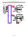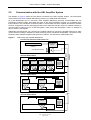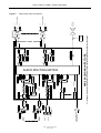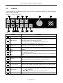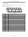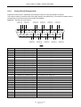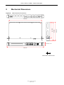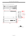
1
VAR4 / VAR12 / VAR20
DSP Audio Router
Product Description
ASL Document Ref.: U-0450-1405.doc
Issue: 04 - complete, approved - Date: 13/08/10
VAR4 / VAR12 / VAR20 - Product Description
This equipment
EC standards:
is
designed
and
manufactured
to
conform
EMC
EN55103-1/E1, EN55103-2/E5, EN50121-4, ENV50204
Safety
EN60065
to
the
following
Failure to use the equipment in the manner described in the product literature will
invalidate the warranty.
A ‘Declaration of Conformity’ statement to the above standards, and a list of auxiliary
equipment used for compliance verification, is available on request.
This product must be disposed of in accordance with the WEEE directive.
Copyright © 2007 Application Solutions Limited
Application Solutions Limited
Safety, Security and Control Division
Unit 17 Cliffe Industrial Estate
Lewes - East Sussex
BN8 6JL - UK
Tel: +44(0)1273 405411
Fax: +44(0)1273 405415
www.asl-electronics.co.uk
All rights reserved.
Information contained in this document is believed to be accurate, however no representation or warranty is given and
Application Solutions Limited assumes no liability with respect to the accuracy of such information.
Issue: 03 complete, approved
Page 2 of 68
VAR4 / VAR12 / VAR20 - Product Description
Contents
1
Introduction .............................................................................................................................................. 7
2
System Overview ..................................................................................................................................... 8
2.1
System Context ........................................................................................................................ 10
2.2
Communication with the ASL Amplifier System ....................................................................... 12
3
Audio Router Functions ........................................................................................................................ 13
3.1
Architecture............................................................................................................................... 13
3.1.1
Audio Routing ................................................................................................................... 13
3.2
Audio Inputs.............................................................................................................................. 15
3.2.1
Mic/Line Inputs.................................................................................................................. 16
3.2.1.1 Paging Microphone Mode ......................................................................................... 17
3.2.1.2 Zoneable Fire Microphone Mode .............................................................................. 17
3.2.1.3 Fire Microphone (ALL-CALL) Mode .......................................................................... 18
3.2.1.4 Single Button Microphone Mode............................................................................... 18
3.2.1.5 Miscellaneous Input Mode ........................................................................................ 18
3.2.1.6 Network Channel Mode............................................................................................. 19
3.2.1.7 Unused Mode............................................................................................................ 19
3.2.1.8 ‘Listen-in’ Function on Station Master Console......................................................... 19
3.2.2
Digital Voice Announcers.................................................................................................. 20
3.2.3
Background Music ............................................................................................................ 20
3.2.4
Mute Input ......................................................................................................................... 20
3.3
Audio Outputs ........................................................................................................................... 21
3.4
Audio Input Priority and Override ............................................................................................. 23
3.5
Fades and Chimes ................................................................................................................... 24
3.5.1
Fades ................................................................................................................................ 24
3.5.2
Chimes.............................................................................................................................. 24
3.5.3
Sequence of Events.......................................................................................................... 24
3.6
Surveillance Tone Detection and Generation........................................................................... 26
3.6.1
Detection........................................................................................................................... 26
3.6.2
Generation ........................................................................................................................ 26
3.7
Control Ports............................................................................................................................. 26
3.7.1
Analogue Interface............................................................................................................ 27
3.7.1.1 Non-monitored Contact Closure to Ground .............................................................. 27
3.7.1.2 Monitored .................................................................................................................. 28
3.7.2
Opto-Isolated Interface ..................................................................................................... 28
3.7.2.1 Contact Closure to Ground ....................................................................................... 28
3.7.2.2 Contact Closure to Supply (+VE going Input) ........................................................... 28
3.7.2.3 Positive Voltage Source (+VE going Input)............................................................... 29
3.7.2.4 Fire Alarm Sounder Interface .................................................................................... 29
3.7.3
Contact Functions ............................................................................................................. 30
3.7.3.1 Routing ...................................................................................................................... 30
3.7.3.1.1 Latching Mode ................................................................................................... 30
3.7.3.1.2 Non-Latching Mode ........................................................................................... 31
3.7.3.2 External Faults .......................................................................................................... 31
3.7.3.3 Remote Fault Accept................................................................................................. 31
3.7.3.4 Music A/B Switching.................................................................................................. 32
3.7.4
Remote Fault Indication.................................................................................................... 32
3.8
Permanent Routes.................................................................................................................... 33
3.9
Remote I/O Units ...................................................................................................................... 34
3.9.1
Analogue Inputs ................................................................................................................ 35
3.9.1.1 Programme Selector Operation ................................................................................ 35
3.9.1.2 Volume Control Operation......................................................................................... 36
3.9.1.3 Ambient Noise Sensor (ANS).................................................................................... 36
3.9.2
Digital Inputs ..................................................................................................................... 38
3.9.3
Digital Outputs .................................................................................................................. 38
3.10
Night Time Volume Control ...................................................................................................... 38
3.11
Test Tone Generation............................................................................................................... 38
Issue: 03 complete, approved
Page 3 of 68
VAR4 / VAR12 / VAR20 - Product Description
4
System Controller Functions................................................................................................................ 39
4.1
Configuration Mode .................................................................................................................. 39
4.2
Test Mode................................................................................................................................. 39
4.3
Fault Monitor Mode................................................................................................................... 39
4.3.1
Real Time Clock (RTC)..................................................................................................... 39
4.3.2
Fault Indication, Acceptance and Clearance .................................................................... 39
4.3.3
Fault Logging .................................................................................................................... 40
4.3.4
Fault Relays and Remote Fault Outputs........................................................................... 40
4.3.5
Remote Diagnostics.......................................................................................................... 40
4.4
Audio Monitor Mode ................................................................................................................. 41
4.5
Software Versions .................................................................................................................... 41
5
Front Panel ............................................................................................................................................. 42
5.1
Indicators .................................................................................................................................. 42
5.2
Controls .................................................................................................................................... 43
5.3
Screen Timeouts ...................................................................................................................... 44
6
Rear Panel............................................................................................................................................... 45
6.1
Audio Inputs.............................................................................................................................. 46
6.1.1
Audio Inputs ...................................................................................................................... 46
6.1.2
Music A+B......................................................................................................................... 46
6.2
Audio Outputs ........................................................................................................................... 47
6.2.1
Base VAR4 Unit ................................................................................................................ 47
6.2.2
Expand Units..................................................................................................................... 48
6.3
Control Ports............................................................................................................................. 49
6.3.1
Control Port 1 (Base VAR4 Unit) ...................................................................................... 49
6.3.2
Control Port 2 (Base VAR4 Unit) ...................................................................................... 51
6.3.3
Control Port 1 (Expand Unit)............................................................................................. 52
6.3.4
Control Port 2 (Expand Unit)............................................................................................. 53
6.3.5
Fault Relay Output Wiring Examples................................................................................ 54
6.3.6
Fire Microphone Wiring Examples.................................................................................... 54
6.3.6.1 Fire Microphone on Input 1 ....................................................................................... 54
6.3.6.2 Fire Microphone on Input 2 ....................................................................................... 55
6.4
Serial Ports ............................................................................................................................... 56
6.4.1
Audio-CAN ........................................................................................................................ 56
6.4.2
RS232 Port ....................................................................................................................... 56
6.4.3
RS485 Port (EXP)............................................................................................................. 57
6.5
DC Supplies (PSU1, PSU2) ..................................................................................................... 57
7
Product Specification ............................................................................................................................ 58
8
Mechanical Dimensions ........................................................................................................................ 61
9
Reference Documents ........................................................................................................................... 63
10
Abbreviations ......................................................................................................................................... 64
11
Index........................................................................................................................................................ 65
Service and Warranty .................................................................................................................................... 67
Issue: 03 complete, approved
Page 4 of 68
VAR4 / VAR12 / VAR20 - Product Description
Document Change History
Issue
Amendment Details
Date
01
First Draft
11/01/07
02
First Release
19/10/07
03
V4.1.0470: CR0450-1494: Induction Loop
CR0450-1496: Selectable Test Tone
Corrections and updates
13/12/07
Issue: 03 complete, approved
Page 5 of 68
VAR4 / VAR12 / VAR20 - Product Description
This page intentionally left blank.
Issue: 03 complete, approved
Page 6 of 68
VAR4 / VAR12 / VAR20 - Product Description
1
Introduction
This document gives an overview on the application, features, interfaces, and functions of the ASL family of
DSP-based Audio Router and Voice Alarm System controllers: the VAR4, VAR12 and VAR20. They are
referred to generically as ‘VAR Router’ in this document. This document contains no definite instruction for
action:
•
The operation is described in the Operation Manual.
•
The installation is described in the Installation Guide.
The document is intended for the use of technical readers who have an understanding of Voice Alarm
Systems and who are trained in general electronics.
Issue: 03 complete, approved
Page 7 of 68
VAR4 / VAR12 / VAR20 - Product Description
2
System Overview
The VAR4, VAR12 and VAR20 are advanced DSP-based Audio Router and Voice Alarm System
Controllers. They allow connection of 4, 12 or 20 audio inputs, which can be routed to 4, 12 or 20 outputs.
Additionally they can monitor and control up to 63 Amplifier Mainframes (V400) and associated amplifier
interface card/surveillance units. Each mainframe connects to the VAR Router via an Audio-CANTM serial
data network and audio monitor bus.
The digital messages may be routed flexibly under the control of the built-in Fire Panel Interface.
The VAR Router comprises a base unit and a number of expand units depending on its capacity as shown in
Figure 1:
•
VAR4:
•
VAR12: VAR4 Base Unit + Expand Unit
•
VAR20: VAR4 Base Unit + 2 Expand Units
Figure 1
VAR4 Base Unit
VAR Router Units – Rear View
EXPAND UNIT-2
(INPUTS/OUTPUTS 13-20)
VAR12
VAR4
VAR4 BASE UNIT
(INPUTS/OUTPUTS 1-4)
VAR20
EXPAND UNIT-1
(INPUTS/OUTPUTS 5-12)
The VAR4 Router includes:
•
Digital storage for 2 x 32-second messages and 2 x 16-second messages.
•
Four universal Mic/Line inputs, each of which supports a serial interface to enable an ASL multi-zone
Paging Microphone to be connected.
All-Call or Zoneable Fire Microphones may be connected to Inputs 1 and 2. These act as All-Call failsafe
override microphones in the event of processor failure as required by BS5839 Part 8.
•
Four A&B audio outputs.
•
Two connections for background music sources, either of which can be selected for routing.
•
Built-in fire alarm interface:
−
10 non-isolated analogue interfaces.
−
12 opto-isolated interfaces.
Issue: 03 complete, approved
Page 8 of 68
VAR4 / VAR12 / VAR20 - Product Description
The VAR12 Router includes:
•
Digital storage for 4 x 32-second messages and 4 x 16-second messages.
•
Twelve universal Mic/Line inputs, each of which supports a serial interface to enable an ASL multi-zone
Paging Microphone to be connected.
All-Call or Zoneable Fire Microphones may be connected to Inputs 1 and 2. These act as All-Call failsafe
override microphones in the event of processor failure as required by BS5839 Part 8.
•
Twelve A&B audio outputs.
•
Two connections for background music sources, either of which can be selected for routing.
•
Built-in fire alarm interface:
−
10 non-isolated analogue interfaces.
−
32 opto-isolated interfaces.
The VAR20 Router includes:
•
Digital storage for 6 x 32-second messages and 6 x 16-second messages.
•
Twenty universal Mic/Line inputs, each of which supports a serial interface to enable an ASL multi-zone
Paging Microphone to be connected.
All-Call or Zoneable Fire Microphones may be connected to Inputs 1 and 2. These act as All-Call failsafe
override microphones in the event of processor failure as required by BS5839 Part 8.
•
Twenty A&B audio outputs.
•
Two connections for background music sources, either of which can be selected for routing.
•
Built-in fire alarm interface:
−
10 non-isolated analogue interfaces.
−
52 opto-isolated interfaces.
Three VA system controller modes are provided:
•
Configuration Mode: to commission and configure the system.
•
Test Mode: to initiate and control a number of unit and system test.
•
Fault Monitor Mode: to act as a comprehensive fault display.
•
Audio Monitor Mode: to monitor the audio output of any input signal, DVA message or amplifier output,
via both the built in loudspeaker and LCD display.
The VAR Router front panel provides a menu-driven interface and contains keys used to navigate the
menus. Alteration of the VAR Router, amplifier and surveillance settings is controlled by access code.
The VAR Router products support a dial-in diagnostic interface allowing interrogation of fault status from a
remote site. Because all parameters are controlled digitally, it is also possible to adjust routing and audio
parameters remotely.
A VAR-NIA Network Interface Adapter provides the VAR12 and VAR20 with networking capability. The
VAR-NIA interfaces the VAR12 or VAR20 to an Intellevac Network, enabling announcements and DVA
messages broadcast from an Intellevac Network’s Audio Control Unit (ACU) or any microphone connected to
it. The Intellevac Network is the solution for large sites, where the VAR Routers can be networked to form
multiple equipment room installations. For details on the Intellevac Network refer to the Intellevac [Table 8-7],
or VAR8-ACU documentation [Table 8-6]. For details on the VAR-NIA, refer to the VAR-NIA Product Manual
[Table 8-5].
Issue: 03 complete, approved
Page 9 of 68
VAR4 / VAR12 / VAR20 - Product Description
2.1
System Context
The diagram in Figure 2 shows the VAR Router in system context. A number of audio inputs feed the VAR
Router. Typically, these include ASL DMS-series paging microphone stations, ASL FMS-series Emergency
Fireman’s microphones (All-Call or Zoneable) and various background music sources. The function of the
VAR Router is to connect these sources, as required to a number of audio outputs, which, in turn, feed
power amplifiers and loudspeakers.
Additionally the VAR Router contains Digital Voice Announcers (DVAs). These are controlled by the Fire
Alarm Panel to broadcast Alert or Evacuate messages to the building.
Figure 3 shows an example of VAR12 and VAR20 Routers connected to an Intellevac Network via a
VAR-NIA Network Interface Adapter. The Audio Control Unit in this example is a wall mount Intellevac ACU.
Figure 2
VAR Router in System Context
V400
AMPLIFIER MAINFRAME
SPEAKER CIRCUITS
A
OUTPUT 1
B
V400
AMPLIFIER MAINFRAME
SPEAKER CIRCUITS
A
OUTPUT n
VAR
ROUTER
A
B
A
B
A
B
B
FIRE
ALARM
PANEL
BMB01
REMOTE I/O UNIT
FMS10
FIRE MICROPHONE
AMBIENT NOISE SENSOR
VOLUME CONTROL
PROGRAMME SELECTOR
DMS20
PAGING MICROPHONE
BACKGROUND MUSIC
DMS10
PAGING MICROPHONE
BACKGROUND MUSIC
Issue: 03 complete, approved
Page 10 of 68
VAR4 / VAR12 / VAR20 - Product Description
Figure 3
VAR12/20 Router Network Application with Intellevac ACU
V400
AMPLIFIER MAINFRAME
DMS20
CENTRAL
PAGING MICROPHONE
SPEAKER CIRCUITS
A
ALERT
OUTPUT 1
EVACUATE
CENTRAL
FIRE ALARM
PANEL
B
MIC
V400
AMPLIFIER MAINFRAME
DATA
VAR-NIA
CENTRAL
BACKGROUND
MUSIC
SPEAKER CIRCUITS
A
OUTPUT n
A
B A
B
B
LOCAL
FIRE ALARM
PANEL
VAR12
DMS10
LOCAL
PAGING MICROPHONE
ALERT
EVACUATE
MIC
DATA
DMS20
LOCAL
PAGING MICROPHONE
LOCAL
BACKGROUND MUSIC
ACU
AUDIO CONTROL UNIT
AND CONTROL
EMERGENCY
MICROPHONE
V400
AMPLIFIER MAINFRAME
SPEAKER CIRCUITS
A
ALERT
OUTPUT 1
EVACUATE
B
MIC
V400
AMPLIFIER MAINFRAME
DATA
AUDIO RING (3x)
VAR-NIA
SPEAKER CIRCUITS
A
DATA RING (1x)
OUTPUT n
A
B A
B
B
LOCAL
FIRE ALARM
PANEL
VAR20
BMB01
REMOTE I/O UNIT
AMBIENT NOISE SENSOR
LOCAL
BACKGROUND MUSIC
DMS10
LOCAL
PAGING MICROPHONE
VOLUME CONTROL
PROGRAMME SELECTOR
DMS20
LOCAL
PAGING MICROPHONE
FMS10
LOCAL
FIRE MICROPHONE
INTELLEVAC EMERGENCY
NETWORK
Issue: 03 complete, approved
Page 11 of 68
VAR4 / VAR12 / VAR20 - Product Description
2.2
Communication with the ASL Amplifier System
The diagram in Figure 2 shows the VAR Router connected to the ASL Amplifier System. The VAR Router
communicates with each Amplifier Mainframe processor via a CAN serial data network.
Up to 63 Mainframes can be connected. Each Amplifier Mainframe processor communicates with the
Surveillance Interface Cards, associated with each of the internal amplifier modules, via a separate intraframe interface. The VAR Router is therefore able to communicate with each Amplifier Surveillance Interface
Card for configuration and fault reporting purposes. Each mainframe has four ‘slots’ for amplifier modules. A
100 W module occupies one ‘slot’, a 200 W amplifier 2 ‘slots’ and a 400 W amplifier 4 ‘slots’. An example of
each is shown in the diagram.
Additionally the VAR Router can command any amplifier interface to connect the amplifier output to an audio
monitor bus thus making it available for audio monitoring at the VAR Router loudspeaker. The audio monitor
bus daisy chains between amplifiers along with the CAN bus. This interface is called Audio-CAN.
Figure 4
VAR Router and Amplifier Mainframes
VAR AUDIO ROUTER AND SYSTEM CONTROLLER
VAR
PROCESSOR
SYSTEM
FAULT DISPLAY AND COMMISIONING
FUNCTION
AUDIO MONITOR FUNCTION
SURVEILLANCE
INTERFACE
SURVEILLANCE
INTERFACE
SURVEILLANCE
INTERFACE
SURVEILLANCE
INTERFACE
100W
100W
100W
100W
AMP
AMP
AMP
AMP
SLOT-1
SLOT-2
SLOT-3
SLOT-4
MAINFRAME
PROCESSOR
SYSTEM
ID: 01
AMPLIFIER MAINFRAME #02
SURVEILLANCE
INTERFACE
SURVEILLANCE
INTERFACE
200W
200W
AMP
AMP
SLOT-1
SLOT-3
MAINFRAME
PROCESSOR
SYSTEM
ID: 02
AMPLIFIER MAINFRAME #63
SURVEILLANCE
INTERFACE
MAINFRAME
PROCESSOR
SYSTEM
400W
AMP
SLOT-3
Issue: 03 complete, approved
Page 12 of 68
ID: 63
CAN BUS
AUDIO BUS
AMPLIFIER MAINFRAME #01
VAR4 / VAR12 / VAR20 - Product Description
3
Audio Router Functions
3.1
Architecture
The diagram in Figure 5 shows the audio architecture of the VAR20. The other variants have an identical
architecture but reduced numbers of Mic/Line Inputs and DVAs.
The majority of audio processing functions are performed by DSP software. However, inputs 1 and 2 support
failsafe Fire Microphone routing whereby the DSP elements are bypassed in the event of processor failure or
software mis-operation. The Voice Alarm system is available for emergency announcements within 1.5
seconds of power-up. To achieve this, the VAR Router goes into to failsafe override mode:
•
immediately after power-up; and
•
immediately after a reset causing a reboot sequence.
So that the Fire Microphones are available for All-Call announcements.
Adjustable parameters are shown in the grey boxes in the figure. These are controllable by the user interface
menu system described in the VAR Router Operation Manual.
3.1.1
Audio Routing
The VAR Router is able to concurrently route any of the potential input sources to any of the outputs.
Inputs are assigned priorities so that higher priority inputs override lower priority ones; see Section
“3.4 Audio Input Priority and Override”.
Five types of routing of the audio inputs are provided·
•
Permanent Route
See Section “3.8 Permanent Routes”.
•
Latent Route(s) activated by contact closure(s)
See Section “3.7.3.1 Routing”.
•
Under the control of Microphone Station
See Section “3.2.1 Mic/Line Inputs”.
•
Under Control of Fire Alarm System (DVA Routing)
•
Remotely by a host computer via a serial interface
Issue: 03 complete, approved
Page 13 of 68
Issue: 03 complete, approved
Page 14 of 68
ATTENUATOR
HF EQ:
+-12dB
MID EQ:
+-12dB
HF EQ:
+-12dB
DVA
MESSAGE#12
DVA
MESSAGE#1
GAIN:
0 to -63dB
OUTPUT-20
OUTPUT-2
OUTPUT-1
RELATIVE GAIN
0 to -40dB
OUTPUT-20
OUTPUT-2
OUTPUT-1
RELATIVE GAIN
0 to -40dB
LEVEL:
0 to -63dB
LEVEL:
0 to -63dB
LEVEL: O to -40dB
(rel: +10dBu)
HARD
LIMITER
(+2.5dBu)
LEVEL: O to -40dB
(rel: +10dBu)
HARD
LIMITER
(+2.5dBu)
AUDIO MONITOR VOLUME
0 to -63dB UNDER CONTROL
OF ROTARY KNOB
MODE: OFF/LF
SURVEILLANCE
TONE
GENERATOR
8 BAND GRAPHIC EQ:
+-12dB
MODE: ON/OFF
MODE: OFF/LF
SURVEILLANCE
TONE
GENERATOR
8 BAND GRAPHIC EQ:
+-12dB
MODE: ON/OFF
VAR-20 AUDIO ARCHITECTURE:
AS ABOVE
OUTPUT GAINS
FADE UP:0.0-5.0s
FADE DOWN:0.0-5.0s
DIFFERENT SETTINGS FOR A or B SELECTION
OUTPUT-20
OUTPUT-2
OUTPUT-1
FADE UP:0.0-5.0s
FADE DOWN:0.0-5.0s
OUTPUT GAINS
LEVEL: O to -40dB
CHIME
GENERATOR
AS ABOVE
LF EQ:
+-12dB
MODE:
OFF
CHIME-1
CHIME-2
CHIME-3
GAIN:
0 to -63dB
MID EQ:
+-12dB
MODE: OFF/LF
LF EQ:
+-12dB
SURVEILLANCE TONE
DETECTOR
SENS: O to -40dB
200Hz
HPF
RELATIVE GAIN
0 to -40dB
OUTPUT GAINS
AUDIO ROUTING MATRIX
OVERRIDE GAIN:
0 to -63dB
ALARM
SOUNDER
SIGNALS
ALL ELEMENTS IN CENTRAL BOX PERFORMED USING DIGITAL SIGNAL PROCESSING. REMAINING ELEMENTS ARE HARDWARE
ATTENUATOR
GAIN: 0 to-63dB
PREAMP
SENS: MIC/LINE
GAIN: 0 to-63dB
PREAMP
(STEREO PHONO MIXED
TO MONO)
AMPLIFIER MONITOR
AUDIO BUS INPUT
MUSIC-B
MUSIC-A
MIC/LINE
INPUT#20
PHANTOM: ON/OFF
MIC/LINE
INPUT#1
HPF: ON/OFF
SWITCHES ACTIVATED IN
HARDWARE-BYPASS MODE
B-OUT
OUTPUT CHANNEL#20
A-OUT
B-OUT
OUTPUT CHANNEL#1
A-OUT
INTERNAL
LOUDSPEAKER
BALANCED
DRIVER
Figure 5
PHANTOM: ON/OFF
SENS: MIC/LINE
OVERRIDE GAIN:
0 to -63dB
VAR4 / VAR12 / VAR20 - Product Description
VAR Router Audio Architecture
VAR4 / VAR12 / VAR20 - Product Description
3.2
Audio Inputs
Dependent on model, the VAR Router has 4,12 or 20 electronically balanced universal inputs, these have
switchable sensitivity to accept microphone or line level signals, and have digitally controlled adjustable
analogue gain prior to the DSP. These analogue gain settings are non-volatile and retained even after power
failure and/or processor failure.
Each of these inputs features a serial communications interface to allow any ASL microphone to be
connected.
The first two of these inputs can also be used for ASL emergency or Fireman’s Microphones in Voice Alarm
systems, this is because they have the facility for an analogue bypass mode in the event of processor
failure/mis-operation, as required by BS5839 Pt 8. In the event of processor failure or communication failure,
the operation reverts to All-Call mode. These two inputs also support DVA routing for triggering DVA
messages.
Two Music inputs are provided, Music A and Music B. These accept stereo phono connections which are
mixed to mono internally. It must be noted that these Music inputs are pre-selectable in the analogue domain
prior to DSP routing. This allows two alternative background music sources to be connected. Only one can
be routed at a time.
Each VAR Router provides a number (2, 4 or 6 dependent on model) of Long DVA messages (32 seconds)
and a matching number of Short DVA (16 seconds) messages. These are treated as additional inputs to the
routing matrix.
One additional input is provided on the Audio-CAN port, this is the Amplifier Audio Monitor Bus.
All inputs described above feed a DSP Audio Routing Matrix. Audio is soft-switched to prevent clicks, and
fade times can be assigned suitable for background music applications.
Issue: 03 complete, approved
Page 15 of 68
VAR4 / VAR12 / VAR20 - Product Description
3.2.1
Mic/Line Inputs
Each of the Mic/Line Inputs may be configured for a particular input type. The following sections describe the
operation and routing of each input type. Table 1 summarises the VAR Router Mic/Line capabilities.
Table 1
VAR Router Mic/Line Input Capabilities
Inputs
1 and 2
3 and 4
Available Input Types
ASL Fire Microphone
N/A
ASL Zoned Fire Microphone
ASL Paging Microphone
Up to 30 microphone buttons
configurable for zone select, DVA
routing, all call, or route reset.
ASL Single Button Microphone
PTT routing.
Miscellaneous Input
N/A
Network Channel
N/A
ASL Paging Microphone
Up to 30 microphone buttons
configurable for zone select, all call,
or route reset.
ASL Single Button Microphone
PTT routing.
Miscellaneous Input
N/A
Network Channel
N/A
ASL Paging Microphone
Up to 20 microphone buttons
configurable for zone select, all call,
or route reset.
ASL Single Button Microphone
PTT routing.
Miscellaneous Input
N/A
ASL Paging Microphone
Up to 10 microphone buttons
configurable for zone select, all call,
or route reset.
ASL Single Button Microphone
PTT routing.
Miscellaneous Input
N/A
ASL Paging Microphone
Up to 5 microphone buttons
configurable for zone select, all call,
or route reset.
ASL Single Button Microphone
PTT routing.
Miscellaneous Input
N/A
5 to 8
9 to 12
13 to 20
L
Microphone Buttons
VAR Router Applicability
VAR4, VAR12, or VAR20
VAR12 and VAR20
Option available only on Input 1.
Input 1 is used for network
operation when the VAR12 or
VAR20 is connected to a VARNIA.
VAR12 and VAR20
VAR12 and VAR20
Inputs 3 and 4 are normally
used for network operation
when the VAR12 or VAR20 is
connected to a VAR-NIA.
VAR12 and VAR20
VAR12 and VAR20
VAR20
All inputs can be configured to Unused mode. In this mode the input is excluded from routing and audio
monitoring.
Issue: 03 complete, approved
Page 16 of 68
VAR4 / VAR12 / VAR20 - Product Description
3.2.1.1
Paging Microphone Mode
It is possible to set any of the Mic/Line inputs for Paging Microphone operation. When configured for this
mode of operation, any ASL Paging Microphone can be supported. For example: DMS5, DMS10, DMS20.
These units are desk consoles that provide zone selection buttons and indicators to show which buttons are
selected and which zones are currently ‘busy’, i.e. in use by another user. The zone selection buttons are
programmable by the VAR Router to correspond to the required outputs or groups of outputs (Mic Routing).
If a Paging Microphone is connected to inputs 1 or 2 the zone selection buttons are also programmable by
the VAR Router for DVA Routing. The primary function is triggering DVAs although it can connect any
desired combination of inputs to outputs. The operation and configuration are similar to that of Latent
Routes; see Section “3.7.3.1 Routing”. Note that a button cannot be assigned as control to switch between
Music A and Music B phono inputs.
Any microphone button may be programmed as an All-Call button. This button is equivalent to pressing all
other configured zone selection buttons.
The security key-switch, when configured, protects the button function. When protected, the key must be
turned on for the button function to be allowed. The security key is intended to safe guard emergency DVA
triggers from inadvertent operation, but may be used protect buttons used only for paging.
The button and LED data is communicated between the Microphone and VAR Router by means of a
dedicated RS485 data link provided on each Mic/Line Input.
3.2.1.2
Zoneable Fire Microphone Mode
Zoneable Fire Microphone operation is configurable for inputs 1 & 2 only. Any ASL Zoneable Fire
Microphone may then be connected. For example: FMS5, FMS10, and FMS20.
These units provide zone selection buttons and indicators to show which buttons are selected and which
zones are currently ‘busy’, i.e. in use by another user. The zone selection buttons are programmable by the
VAR Router to correspond to certain outputs or groups of outputs (Mic Routing).
The zone selection buttons are also programmable by the VAR Router for DVA Routing. The primary
function is triggering DVAs although it can connect any desired combination of inputs to outputs. The
operation and configuration are similar to that of Latent Routes; see Section “3.7.3.1 Routing”. Note that a
button cannot be assigned as control to switch between Music A and Music B phono inputs.
Any microphone button may be programmed as an All-Call button. This button is equivalent to pressing all
other configured zone selection buttons.
The security key-switch, when configured, protects the button function. When protected, the key must be
turned on for the button function to be allowed. The security key is intended to safe guard emergency DVA
triggers from inadvertent operation, but may be used protect buttons used only for paging.
The Zoneable Fire Microphones use the same serial control interface as the Paging Microphones to
communicate button and LED status.
As well as a serial interface, a hardwired PTT is interfaced to the VAR Router. This switch is provided with
resistors to allow the cabling to be monitored for faults.
A hardwired SPEAK-NOW LED and ALL-CALL-ONLY LED are also provided. Operation is as described
below:
•
Normal Operation
In normal operation, all routes are set up via the serial interface, and audio is routed via the DSP. The
hardware ALL-CALL contact is used as the PTT in order to provide BS5839 functionality.
A hardwired SPEAK-NOW LED is illuminated on the Fire Microphone once the route is made (and chime
has sounded).
Issue: 03 complete, approved
Page 17 of 68
VAR4 / VAR12 / VAR20 - Product Description
•
Failsafe Operation
If the VAR Router detects processor failure or mis-operation, a hardware bypass mode comes into
operation for the Fire Microphones. When this happens the Router provides an ALL-CALL-ONLY signal
back to the Fire Microphone, which illuminates the ALL-CALL-ONLY LED on the Fire Microphone panel.
When the PTT is pressed, an All-Call analogue bypass path is driven which bypasses all processor
controlled elements.
The hardwired SPEAK-NOW LED is illuminated on the Fire Microphone once the route is made.
If the RS485 communications link fails but the VAR Router processor is running correctly the ALL-CALLONLY LED is illuminated and operation reverts to all-call. However in this case the audio is still routed
through the DSP.
3.2.1.3
Fire Microphone (ALL-CALL) Mode
Fire Microphone operation is configurable for inputs 1 & 2 only. Any ASL All-Call Fire Microphone may then
be connected. For example: FMS1, EAP01.
All-Call Microphones do not need a serial interface. However, the serial interface may be installed if a busy
LED function is required. These microphones have a hardwired PTT switch interfaced to the VAR Router,
this switch is provided with resistors to allow the cabling to be monitored for faults by the VAR Router.
A hardwired SPEAK-NOW LED is also provided. Operation is as described below:
•
Normal Operation
In normal operation, All-Call is initiated by the controller monitoring the state of the contact and routing
audio via the DSP to all outputs.
A SPEAK-NOW LED is provided on the Fire Microphone, and is driven by the processor once the route
is made (and chime has sounded).
•
Failsafe Operation
If the VAR Router detects processor failure or mis-operation, a hardware bypass mode comes into
operation for the Fire Microphones.
When the PTT is pressed, an All-Call analogue bypass path is driven which bypasses all processor
controlled elements.
The SPEAK-NOW LED is illuminated on the Fire Microphone once the route is made.
3.2.1.4
Single Button Microphone Mode
It is possible to set any of the Mic/Line inputs for Single Button Microphone Operation. For example: SAP01.
A Single Button Microphone provides indicators and PTT button. The PTT button can be programmed for
zone selection at the VAR Router to correspond to certain outputs or groups of outputs.
The button and LED data is communicated between the Microphone and VAR Router by means of a
dedicated RS485 data link provided on each Mic/Line input.
3.2.1.5
Miscellaneous Input Mode
It is possible to set any of the Mic/Line inputs as Miscellaneous Input Mode. When configured for this mode
of operation, the serial communication interface is disabled and other type of audio input may be connected,
e.g. PC/DVA audio, Long Line PA (LLPA) audio, or an additional background music input. The audio may be
routed by the Permanent Route or Latent Contact Route mechanisms; described respectively in Sections
“3.8 Permanent Routes” and “3.7.3.1 Routing”.
Issue: 03 complete, approved
Page 18 of 68
VAR4 / VAR12 / VAR20 - Product Description
3.2.1.6
Network Channel Mode
By default if a VAR-NIA is connected to VAR12 or VAR20, the VAR Router Inputs will be used as follows:
•
Network Channel 1 – VAR Router Input 1
•
Network Channel 2 – VAR Router Input 3
•
Network Channel 3 – VAR Router Input 4
This is the Intellevac Network standard configuration with 3 network audio channels.
It is possible to implement fewer network channels where concurrent broadcast of ALERT, EVACUATE and
Fire Microphone audio is not required. The corresponding VAR12 or VAR20 inputs would then be available
for connection of local microphones or other audio sources.
3.2.1.7
Unused Mode
It is possible to set any of the Mic/Line inputs to “Unused” Mode. When configured for this mode of operation
they are excluded from routing and audio monitoring.
3.2.1.8
‘Listen-in’ Function on Station Master Console
The ASL Station Master Console (SMC) functions as a normal Zoneable Fire Microphone with additional
‘listen-in’ function provided by an audio feed from the Aux Output (AUX-OUT) on the Control Port 1 of the
VAR Router which feeds a local amplifier and loudspeaker within the console. A key-switch programmable
by the VAR Router and an associated LED control the ‘listen-in’ function. The ‘listen-in’ key may be operated
in ‘Listen-to-All’ or ‘Selective Listen’ mode:
•
‘Listen-to-All’ mode
The audio sources, which are currently routed to outputs associated with zone select buttons, will be
mixed together and routed to the Aux Output. The ‘Listen-to-All’ mode is activated by momentarily
pressing the ‘listen-in’ key. Re-pressing the ‘listen-in’ key momentarily will deactivate the ‘listen-in’
function.
•
‘Selective Listen’ mode
The audio from the source associated with a selected zone is routed to the Aux Output. The ‘Selective
Listen’ mode is activated by holding down the ‘listen-in’ key while simultaneously pressing a zone select
button. It is possible to add other sources to the audio-mix by momentarily pressing the associated zone
select buttons. Re-pressing the listen-in key momentarily will deactivate the ‘listen-in’ function.
Activating the ‘listen-in’ function cause the listen-in LED on the microphone console to latches on.
When the ‘listen-in’ function is active, the normal paging operation will be barred. Neither the zone select nor
PTT buttons will have any effect.
While the ‘listen-in’ function is active, the audio-mix will update accordingly if the routed audio sources
change to the selected zone.
Issue: 03 complete, approved
Page 19 of 68
VAR4 / VAR12 / VAR20 - Product Description
3.2.2
Digital Voice Announcers
Digital Voice Announcer (DVA) messages are divided into two types:
•
Long DVA: up to 32 second message length
VAR4 provides storage for 2 Long DVAs
VAR12 provides storage for 4 Long DVAs
VAR20 provides storage for 6 Long DVAs
•
Short DVA: up to 16 second message length
VAR4 provides storage for 2 Short DVAs
VAR12 provides storage for 4 Short DVAs
VAR20 provides storage for 6 Short DVAs
The DVAs may be configured so that they either stop immediately, part way through a message when
terminated, or can be configured to play the message to the end.
The DVAs are usually controlled by VAR Router contact inputs, which interface to a Fire Alarm panel. Any
VAR Router contact may be assigned to this function. Two modes of operation are supported:
•
Latching: the trigger is latched by the VAR Router. This requires a separate reset input from the Fire
Panel to terminate the route.
•
Non-Latching: a reset signal is not required. The route is terminated when the trigger ends.
The DVAs may be also routed by the Permanent Route mechanism described in Section “Permanent
Routes”.
3.2.3
Background Music
The two phono Music inputs (Music A and B) maybe be routed by two means:
•
Permanent Route: typical for background music.
•
Latent Route(s) activated by contact closure. A separate contact may be specifically assigned as a
music selector to switch between either Music A or Music B sources.
L
3.2.4
Additional music sources may be connected to any Mic/Line input configured as a
Miscellaneous Input.
Mute Input
The VAR Router provides a special ‘Mute’ Input, which mutes even fire microphones if needed. For this
purpose its priority is set to ‘0’ by default. However, the mute input is configurable, so it is possible to mute
just DVAs, and/or any other inputs.
Issue: 03 complete, approved
Page 20 of 68
VAR4 / VAR12 / VAR20 - Product Description
3.3
Audio Outputs
The VAR Router provides 4, 12 or 20 (dependent on model) electronically balanced outputs. These provide
a nominal 0 dBu output, which when fully driven, corresponds to 100 V output from the ASL amplifier. Each
VAR Router output has separate A and B output connections for driving A&B amplifiers with interleaved
speaker circuits. The A and B outputs are isolated so that a short circuit on one output will not affect the
other.
The output is hard-limited to +2.5 dBu. The outgoing surveillance tone is not limited in this way. Thus if the
audio is overdriven, the surveillance tone is not clipped.
The outputs are normally fed from the DSP and all processing is performed in the digital domain. Each
output, is however equipped with an ‘override gain’ setting. This enables independent adjustment, for each
zone, of the level of the Fire Microphones when the VAR Router is in the hardware bypass mode. These
analogue gain settings are non-volatile and retained even after power failure and/or processor failure.
One additional output is provided from the routing matrix; this feeds the internal amplifier/loudspeaker for
Audio Monitoring functions.
The top two outputs of the VAR Router’s base unit and expand units can be configured to feed a 100 V line
driving an amplifier connected to an Induction Loop System, typically the ASL ILP01 Induction Loop Panel.
The number of induction loop outputs is configurable, and the induction loop outputs are allocated from top
down, as detailed in Table 2.
In addition to standard parameters an Induction Loop output has the following Induction Loop specific
parameters:
•
Equalisation
Frequency bands suitable for the Induction Loop type can be adjusted to achieve as flat a frequency
response as is possible.
•
Audio amplitude compression
The amount of compression and the threshold level at which the compression begins can be configured
in order to achieve the best intelligibility and general received sound quality.
The VAR Router provides test tones, which can be used during the commissioning of an Induction Loop
System. See Section “3.11 Test Tone Generation” for further details.
Issue: 03 complete, approved
Page 21 of 68
VAR4 / VAR12 / VAR20 - Product Description
Table 2
VAR Router Induction Loop Outputs
VAR Router
VAR4
Possible Number of Induction Loops
Output Number
Output Location
1
4
Base Unit
3
2
1
2
4
12
11
12
4
VAR12
3
11
12
3
4
4
11
12
1
2
20
19
20
12
3
19
20
11
4
12
19
20
VAR20
4
11
5
12
19
20
3
4
6
11
12
19
20
Issue: 03 complete, approved
Page 22 of 68
Base Unit
Expand Unit 1
Expand Unit 1
Base Unit
Expand Unit 1
Base Unit
Expand Unit 1
Expand Unit 2
Expand Unit 2
Expand Unit 1
Expand Unit 2
Expand Unit 1
Expand Unit 2
Base Unit
Expand Unit 1
Expand Unit 2
Base Unit
Expand Unit 1
Expand Unit 2
VAR4 / VAR12 / VAR20 - Product Description
3.4
Audio Input Priority and Override
The input priority is used to resolve conflicts when two or more inputs try to broadcast to the same output. In
this case the input with the highest priority will be able to broadcast, and the others will not.
19 priority levels available, and can be assigned to any of the audio input sources.
Priority is assignable to each input per output. This is so that different inputs may have different priorities
according to which zone they are serving. For example a particular microphone may have a high priority only
in its local zone, and a lower priority when broadcasting elsewhere.
Assignment of equal priorities to different inputs means that those inputs operate on a ‘first-come-firstserved’ basis.
!
1. Care should be taken in ensuring that Fire Microphones, and Alarm and Emergency DVAs
have a high priority and non-emergency sources, such as Paging Microphones and music
sources, have low priorities.
2. In a networked system it is essential that:
a. The Slave Units are programmed so that they know the Priorities of the Audio Control
Unit’s audio sources in order that priorities can be successfully arbitrated between their
local inputs and the audio inputs into the Audio Control Unit.
b. The Audio Control Units are programmed so that they know the Priorities of the Slave
Unit’s audio sources, in order that priorities can be successfully arbitrated across the
networked system when the Audio Control Unit initiates a remote route.
An override occurs when a higher priority input taker over control of an output broadcast from a lower priority
input.
Table 3 describes the actions in the event of override. The system is able to support up to 40 overrides per
output.
Table 3
Override
Input Type
Action in Event of Override
Fire Microphone
If Inputs 1 and 2 are assigned as Fire Microphones, they operate on a priority
basis (by default 1>2).
If 1 overrides 2 then 2 will be restored immediately that 1 has completed the
announcement.
Zoneable Paging Microphone
Single Button Microphone
When broadcasting to a group of zones the user may be overridden during paging
in any zones in which other users have higher priority. In this case, the original
broadcast will be able to continue to page the remaining zones.
If the override source is removed during the original announcements the
overridden zones will not be re-instated. This is to minimise the broadcast of
potentially ambiguous or annoying message fragments.
DVAs
If a DVA is overridden it is silenced immediately in the zone(s) in which it is
overridden. When the override is removed it is re-instated immediately, i.e. does
not wait until the beginning of the cycle.
Permanent Route
If overridden, the route is restored immediately the override is removed. A soft
fade-up may be desirable if background music is being overridden; this may be
readily programmed for the input being used for the music.
Latent Route
If overridden, the route is restored immediately the override is removed. A soft
fade-up may be desirable if background music is being overridden; this may be
readily programmed for any input that is being used for the music.
Issue: 03 complete, approved
Page 23 of 68
VAR4 / VAR12 / VAR20 - Product Description
3.5
Fades and Chimes
3.5.1
Fades
It is possible to specify a fade up and fade down time for each Mic/Line or Music input source.
This is typically used on background music where a slow fade-up, in particular, is desirable.
The Fade Down time is:
•
The time it takes for the signal to fade down when turned off (un-routed);
•
The time it takes for the signal to fade down before an overriding broadcast is made in its place.
The Fade Up time is the time the signal takes to fade up when:
•
Turned on (routed);
•
Override removed.
Even when the fade parameters are set to zero, a small finite fade is used in order to provide click-free audio
switching.
L
3.5.2
It is important that in order for a DVA or Fire Microphone to be able to override a background
music source quickly, they are set up for a short Fade Down time.
Chimes
It is possible to configure a chime to be broadcast at the start of an announcement from any Mic/Line input
source. Chimes are not assignable to the music inputs or DVAs. However, if desired then chimes can be
recorded as part of DVAs.
The chime is triggered when that source is routed; the actual audio, however, is only routed when the chime
is complete.
It is possible to configure the following chime types:
•
Off: No chime.
•
Chime-1: Single note.
•
Chime-2: Two note descending overlapping pattern.
•
Chime-3: Three note descending overlapping pattern.
3.5.3
Sequence of Events
The diagram in Figure 6 illustrates the sequence of events during the enabling and disabling of a single
audio source (e.g. background music).
Issue: 03 complete, approved
Page 24 of 68
VAR4 / VAR12 / VAR20 - Product Description
Figure 6
Sequence of Events for Single Audio Source
T2
T1
MUSIC AUDIO
MUSIC
FADE UP=T1
FADE DOWN= T2
ON
OFF
The diagram in Figure 7 illustrates the sequence of events during the override of a background music source
by a Paging Microphone with chime.
Note that the background music Fade Down time (T2) not used in this instance. Instead the microphone
Fade Down time (T4) is used.
Figure 7
Sequence of Events for Paging Microphone Chime Overriding a Background Music
T4
T1
MUSIC AUDIO
MUSIC AUDIO
MUSIC
FADE UP=T1
FADE DOWN= T2
ON
MICROPHONE
PTT
OFF
T3
CHIME AUDIO
MIC AUDIO
MICROPHONE
FADE UP=T3
FADE DOWN= T4
T4
ON
MICROPHONE
SPEAK-NOW LED
OFF
Issue: 03 complete, approved
Page 25 of 68
VAR4 / VAR12 / VAR20 - Product Description
3.6
Surveillance Tone Detection and Generation
3.6.1
Detection
The VAR Router is able to detect the presence of a low frequency 20 Hz surveillance tone on the Mic/Line
inputs. ASL Microphones produce this tone as standard.
Surveillance Tone detection can be configured ‘on’ or ‘off’ per input. The detection threshold is adjustable per
input. With surveillance configured to ‘on’ then in the absence of a surveillance tone, or with the surveillance
tone below the detection threshold, then an input audio fault will be raised and logged.
3.6.2
Generation
The VAR Router is capable of generating a low frequency 30 Hz surveillance tone, at each audio output.
Surveillance tone generation is configurable either ‘on’ or ‘off’ or ‘pulsed’ per output. The outgoing tone level
per VAR Router output is also adjustable.
Pulsed surveillance tone uses less power than continuous ‘on’ surveillance.
If configured as ‘pulsed’, the pulse interval is 20 seconds, and the pulse ‘on’ time is 1 second. The ‘on’ and
‘off’ envelope of the pulsed surveillance is so shaped that no audible artefacts can be heard.
3.7
Control Ports
The VAR Router is equipped with control ports for the following functions:
•
DVA Routing (Fire Alarm system interface)
•
Latent Routes
•
External Fault Inputs
The VAR Router is able to provide additional control I/O by means of Remote I/O Units (BMB01), which are
described in Section “3.9 Remote I/O Units”.
The VAR4, 12 and 20 control ports are shown on the rear panel diagram in Figure 8.
Figure 8
VAR Router Control Ports
CONTACTS 43 - 51
CONTACTS 52 - 62
EXPAND UNIT-2
CONTACTS 23 - 31
CONTACTS 32 - 42
EXPAND UNIT-1
BASE VAR4 UNIT
VAR4
VAR12
VAR20
CONTACTS 11 - 22
CONTACTS 1 - 10
Issue: 03 complete, approved
Page 26 of 68
VAR4 / VAR12 / VAR20 - Product Description
All ports on the expand units are opto-isolated interfaces. The base VAR4 unit has two types of control ports;
one is an opto-isolated interface, the other is an analogue port.
The following sections describe the characteristics of the ports.
Table 4
VAR Router Control Ports
VAR
Port Type
VAR4
VAR12
VAR20
3.7.1
Control Port Number
Contacts
Analogue
Base Unit - Port-1
1 – 10
Opto-Isolated
Base Unit - Port-2
11 – 22
Analogue
Base Unit - Port-1
1 – 10
Opto-Isolated
Base Unit - Port-2
11 – 22
Opto-Isolated
Expand Unit 1 - Port-1
23 – 31
Opto-Isolated
Expand Unit 1 - Port-2
32 – 42
Analogue
Base Unit - Port-1
1 – 10
Opto-Isolated
Base Unit - Port-2
11 – 22
Opto-Isolated
Expand Unit-1 - Port-1
23 – 31
Opto-Isolated
Expand Unit-1 - Port-2
32 – 42
Opto-Isolated
Expand Unit-2 - Port-1
43 – 51
Opto-Isolated
Expand Unit-2 - Port-2
52 – 62
Analogue Interface
Contacts 1 to 10 only use a non-isolated analogue interface with an internal pull-up to 5 V. The analogue
interface operates in two modes: ‘non-monitored’ and ‘monitored’. Each contact is individually selectable
between these two modes.
3.7.1.1
Non-monitored Contact Closure to Ground
+5V
4k7 ohms
THRESHOLD= 2.5V
ROUTER
ANALOGUE
CONTACT
INPUT
It may be used to interface a simple contact
closure to ground.
0V
Cabling to Contact
Issue: 03 complete, approved
Page 27 of 68
VAR4 / VAR12 / VAR20 - Product Description
3.7.1.2
Monitored
+5V
4k7 ohms
It may be used to interface resistively monitored
contacts.
This interface enables the VAR Router to monitor
the interface to the Fire Panel or other contact
closure. The contacts must be fitted with
6k8/470R resistors. This method of monitoring
has been used extensively in the past and is
prevalent in continental Europe.
THRESHOLD= 2.5V
ROUTER
ANALOGUE
CONTACT
INPUT
0V
Cabling to Contact
3.7.2
Opto-Isolated Interface
Contacts 11 through to 62 use an opto-isolated interface. The contact is asserted when the opto-isolator is
turned on. These may be used to interface a simple closure, or as a Sounder Circuit Interface that is suitable
for connecting the Fire Alarm to the VAR Router for triggering DVA messages.
3.7.2.1
Contact Closure to Ground
12-40 V
A simple contact closure to ground may be
connected as shown. Note that the external pullup to 24 V is not needed if none of the contacts
on the port are set up for routing. If any contacts
are set up for routing, then the global internal pullups on all contacts of the port are disabled in
order to provide a true volt-free interface for the
routing functions.
ROUTER
CONTACT INPUT
+
I
OPTO ON
WHEN CONTACT
CLOSED
CONTACT
CLOSURE
TO GROUND
3.7.2.2
Contact Closure to Supply (+VE going Input)
12-40 V
In this method a contact closure is not made to
ground, but to a supply, with a fused connection
do ground. This may be appropriate, depending
on the signal source.
ROUTER
CONTACT INPUT
CONTACT
CLOSURE
TO SUPPLY
Note that for reliable operation it is recommended
that the 0 V reference is taken back to the 0 V of
the equipment that supplies the +VE signal.
Issue: 03 complete, approved
Page 28 of 68
+
I
OPTO ON
WHEN CONTACT
CLOSED
VAR4 / VAR12 / VAR20 - Product Description
3.7.2.3
Positive Voltage Source (+VE going Input)
ROUTER
CONTACT INPUT
As per Contact Closure to Supply, but to an
alternatively switched voltage source, such as to
a suitable output from another piece of
equipment.
12-40 V
FROM
REMOTE
EQUIPMENT
+
I
OPTO ON
WHEN CONTACT
CLOSED
3.7.2.4
Fire Alarm Sounder Interface
The opto-isolated inputs may be used as a
reverse polarity sounder circuit interface to a Fire
Alarm system. In this DVA triggering method the
link between the fire panel and the VA system is
monitored at the Fire Panel by means of End of
Line
Resistors.
This
is
the
current
recommendation of BS5839. The Fire panel
monitors the current flowing in the End of Line
Resistor. Reversing the polarity activates the
input.
FIRE
SYSTEM
Cabling to Fire System
-V
I
+V
+
-
I
END OF LINE
RESISTOR
OPTO OFF
The VAR Router does not have end of line
resistors fitted as standard, as the value required
varies according to the Fire Alarm system. The
desired value for a particular job must be
specified with the order. ASL can then factory-fit
the appropriate resistors.
Alternatively these resistors may be fitted local to
the VAR Router during installation. Note that in
this method the final connection into the VAR
Router is not monitored.
ROUTER
CONTACT INPUT
MONITORING
ROUTER
CONTACT INPUT
FIRE
SYSTEM
Cabling to Fire System
+V
I
-V
+
-
END OF LINE
RESISTOR
I
OPTO ON
ACTIVE
Issue: 03 complete, approved
Page 29 of 68
VAR4 / VAR12 / VAR20 - Product Description
3.7.3
Contact Functions
3.7.3.1
Routing
Any contact may be configured to control Latent Routes, i.e. pre-programmed routes which are controlled by
a contact closure. Routes may be assigned as Non-latching or Latching. In the latter case, a separate
contact may be assigned as a matching ‘reset’ contact.
3.7.3.1.1
Latching Mode
Any contact may be configured to trigger a latched Latent Route. A momentary, or prolonged, activation of a
latching trigger initiates routing. A separate contact is required for latching inputs, to act as a ‘reset’ contact.
This method is normally used to trigger emergency DVAs from fire systems, although any input source may
be routed in this way. For Fire Alarm DVA messages, BS5839 Pt 8 recommends the use of latched triggers
with separate resets, so that the message will continue to run even if the trigger pair fails.
Each latching trigger can be configured to initiate routing of any DVA to any output. It is possible to initiate
simultaneous routing of multiple DVAs to multiple outputs with a single trigger. This is so that, for example,
Alert and Evacuate messages may be able to be broadcast to different zones for a single trigger. The DVA
or DVAs will play until a momentary assertion of the matching ‘reset’ line, unless the corresponding trigger is
still asserted, in which case the DVA will not be reset.
L
It is possible to configure whether or not a particular route causes busy indications to be shown
on microphone consoles.
For example, a busy indication would not be desired if the Latent Route mechanism was to be
used for enabling a background music source.
If used as a DVA trigger, the contact is configurable for two modes: ‘DVA Full’ and ‘DVA Part’.
•
DVA Full
In the ‘DVA Full’ mode, when the ‘reset’ is received, the DVA or DVAs will complete its full message
cycle and broadcast till the end of the DVA message before ending.
•
DVA Part
In the ‘DVA Part’ mode, when the ‘reset’ is received, the DVA or DVAs will end immediately even if part
way through a DVA message broadcast.
DVAs can be assigned priorities as described in Section “3.4 Audio Input Priority and Override”. Once
triggered, DVAs may be overridden by any higher priority DVAs, or other inputs that are routed to the same
output.
L
A group of route triggers may share a single reset, or each route trigger can have its own
dedicated reset. If multiple DVA routes have been triggered by consecutive triggers in a single
group, the activation of that group’s ‘reset’ line unlatches all the DVA routes associated with that
reset. However, if any of the triggers are still asserted, these DVAs will continue to play, while
the others will be reset.
Issue: 03 complete, approved
Page 30 of 68
VAR4 / VAR12 / VAR20 - Product Description
3.7.3.1.2
Non-Latching Mode
Any contact may be configured to trigger a so-called non-latching Latent Route.
When the contact is made, a pre-programmed route is set up. When the contact is released, the route is
cleared, no separate ‘reset’ input is required.
Application examples are (1) when simple paging is required (not using ASL microphones) or (2) when
background music needs to be routed to selectable areas.
It is possible to use the Latent Route mechanism to allocate any output to any audio input, Mic/Line, DVA, or
Music.
L
It is possible to configure whether or not a particular Latent Route causes busy indications to be
shown on microphone consoles.
For example, a busy indication would not be desired if the Latent Route mechanism was to be
used for enabling a background music source.
If a Latent Route is used to trigger a DVA, the trigger is configurable for two modes as for a latching route:
•
DVA Full
In the ‘DVA Full’ mode, when the trigger is de-asserted, the DVA(s) completes its full message cycle
before ending.
•
DVA Part
In the ‘DVA Part’ mode, when the trigger is de-asserted, the DVA(s) ends immediately even if part way
through a DVA message broadcast.
When a Latent Route is made and the routes set up, any further routes added via the VAR Router userinterface are automatically added to the existing routes. Similarly routes may be removed via the user
interface ‘on-the-fly’. That is to say: it is not necessary to de-assert and then re-assert the Latent Route in
order to recognise changes in the Latent Route set up.
Although two music inputs, A+B, are provided, they are switched in the analogue domain before digitisation.
Therefore only one may be routed at a time. The application example is where a background music source is
required but may be chosen from CD player or radio Tuner.
Music may be routed via the Latent Route mechanism, any other contact may be assigned as switch to
select either A or B. this is useful for selecting between two alternative music sources, i.e. Tuner or CD
player.
3.7.3.2
External Faults
Any contact may be configured as an external fault input.
It is possible to assign an 18 character alphanumerical description to a contact input when it is configured as
an external fault input.
This is to enable external equipment which provide normally closed relay contacts to indicate healthy status,
to be integrated into the VAR Router fault monitoring system. A typical example in a VA system is the battery
charger.
An active low contact closure on the port indicates a ‘no fault’ condition. Open circuit on the port will cause a
fault to be reported and logged. The specific fault that is raised will be identified by the alphanumerical
description.
3.7.3.3
Remote Fault Accept
The VAR Router provides outputs to drive a remote Fault Panel (see Section “Remote Fault ”); typically this
consists of a drive to a sounder, and fault LED. Any contact may be configured as the ‘Accept’ for the remote
Fault Panel; this acts as a local ‘fault accept’ button affecting only the remote indication.
Issue: 03 complete, approved
Page 31 of 68
VAR4 / VAR12 / VAR20 - Product Description
3.7.3.4
Music A/B Switching
Music may be routed via the Latent Route mechanism as mentioned in Section “3.7.3.1.2 Non-Latching
Mode”, any contact may be assigned as a control to switch between Music A and Music B phono inputs.
3.7.4
Remote Fault Indication
Besides the analogue and opto-isolated contacts the VAR Router provides two open collector outputs on the
base VAR4 unit Control Port 1, REMOTE FAULT-1 and REMOTE FAULT-2. These outputs are designed to
drive a remote Fault Panel. This panel enables remote fault indication and annunciation.
Each output is configurable by the VAR Router to drive a sounder, a fault LED, or an emergency DVA
indicator. Any contact may be configured to act as a local ‘fault accept’ button for the remote Fault Panel,
see Section “3.7.3.3 Remote Fault Accept”.
Issue: 03 complete, approved
Page 32 of 68
VAR4 / VAR12 / VAR20 - Product Description
3.8
Permanent Routes
It is possible to program specific inputs to be permanently allocated to specific outputs. Such routes are
‘permanent’ unless overridden by a higher priority input. The route is restored once the higher priority input is
removed.
The typical scenario is background music, which may want to be assigned to certain areas. For example, to
route music to the shop-floor areas in a factory complex unless another broadcast was active. It is possible
to allocate any output to any audio input by means of the permanent route mechanism.
Although two music inputs, A+B, are provided, they are switched in the analogue domain before digitisation.
Therefore only one may be routed at a time. Either Music A or Music B may be routed by the Permanent
Route mechanism. If, however both are selected Music A will have priority over Music B and all routes using
Music B will switch to Music A.
If concurrent permanent routes are required to disparate zones, for example to route different music to two
different areas, then the background music input can be used for one source and Mic/Line Inputs should be
used for the additional music sources.
L
A permanent route does not cause a busy indication on any microphone, otherwise all zones
would appear permanently busy in a scenario where background music feeds all zones.
Issue: 03 complete, approved
Page 33 of 68
VAR4 / VAR12 / VAR20 - Product Description
3.9
Remote I/O Units
The VAR Router is able to support the connection of up to 9 Remote I/O units (ASL Product: BMB01).
The BMB01 units provide additional analogue and opto-isolated digital inputs, and open collector digital
outputs. This extends the control and interfacing capability of the system. The BMB01 units are interfaced via
a power and RS485 data link that can be up to 1 km long, in order to interface to remote equipment.
Each BMB01 Remote I/O Unit provides the I/O capability as described in Table 5.
Table 5
Remote I/O Unit Inputs and Outputs
Type
Quantity
Functions
Analogue Input
non-isolated
12
Programme Selector
Volume Control
Ambient Noise Sensor (ANS)
Fault Input
Digital Input
opto-isolated
12
Routing Control
Reset Input
Fault Input
Digital Output
open-collector
12
Busy Output
The VAR4 provides a single RS485 bus for the connection of the Remote I/O Units. The VAR12 and 20
provide 2 and 3 such busses respectively. These are labelled EXP on the rear panels. See the examples
shown in Figure 9.
Up to 9 Remote I/O Units may be connected in total each with a unique address set up using an internal
rotary switch. The Remote I/O Units can be connected to any of the RS485 busses.
If using a VAR12 or VAR20, in order to optimise response time, it is sensible to distribute them across the
alternative busses.
Figure 9
Remote I/O Connection to RS485 Busses
Example using VAR4:
RS485
1
2
3
7
8
9
4
5
6
1
2
3
Example using VAR20:
RS485-3
RS485-2
RS485-1
Issue: 03 complete, approved
Page 34 of 68
= 120 ohm
TERMINATION FITTED
VAR4 / VAR12 / VAR20 - Product Description
The RS485 data link to the Remote I/O Units is fully monitored. In the event of communications failure, the
VAR Router will log a fault. The fault code identifies the specific unit or units that are affected.
L
3.9.1
•
The maximum recommended distance for the RS485 data link is 1 km.
•
Only the last physical Remote I/O Unit in the chain should have the RS485 termination
enabled.
•
A single RS485 bus supports up to 3 Remote I/O Units.
Analogue Inputs
Each analogue input channel may be assigned as
either a Programme Selector, a Volume Control,
an ANS Sensor, or a Fault Input.
The Programme Selector and Volume Control
functions use a 12 step resistive ladder switch
arrangement shown in Figure 10.
Figure 10
BMB01 Analogue Inputs
12
+5V
11
4k7 ohms
10
ASL produces a range of Selector and Volume
Control products that are suitable for standard
wall plate mounting.
The fault input is simply a contact closure to
ground, which operates as described in Section
“3.7.3.2 External Faults”.
2
ANALOGUE
INPUT
1
0V
Cabling to Contact
3.9.1.1
Programme Selector Operation
The application of the Programme Selector function is to allow remote selection of alternative sources to a
specific zone or zones. Normally the programme selector will be mounted within the zone and allow selection
of alternative sources, such as different background music sources.
It is possible to assign a particular Programme Selector to be associated with one, or any group of, VAR
Router outputs. It is then possible to assign which input each position of the Programme Selector
corresponds to.
The connection between the Remote I/O Unit and the Programme Selector is monitored, so that open and
short conditions on the cabling are detected and logged by the VAR Router. The VAR Router fault report
identifies the specific Remote I/O Unit and the particular analogue channel number affected.
In the event of such a fault, the routing defaults to that set up on position ‘1’. Normally this would correspond
to all routes being ‘off’.
The same default operation occurs in the event of RS485 communications failure to the Remote I/O Unit.
L
There should be only one Programme Selector associated with an output or group of outputs.
Associating an output with more than one Program Selector would cause unpredictable results.
Issue: 03 complete, approved
Page 35 of 68
VAR4 / VAR12 / VAR20 - Product Description
3.9.1.2
Volume Control Operation
The application of the Volume Control function is to allow remote control of the volume of specific input
sources within a specific zone or zones. Normally the volume control will be mounted within the zone and
allow the control of the specific sources, such as background music sources, while leaving the volume of all
other sources unaffected.
It is possible to assign a particular Volume Control to be associated with one, or any group of, VAR Router
outputs. It is then possible to assign which input, or group of inputs, are controlled.
Each step of the volume control gives exactly 3dB attenuation, with position ‘1’ being ‘off’.
The connection between the Remote I/O Unit and the Volume Control is monitored, so that open and short
conditions on the cabling are detected and logged by the VAR Router. The VAR Router fault report identifies
the specific Remote I/O Unit and the particular analogue channel number affected.
In the event of such a fault, the volume will default to that set up on position ‘off’, i.e. the maximum level.
The same default operation occurs in the event of RS485 communications failure to the Remote I/O Unit.
L
3.9.1.3
Only one Volume Control should be configured to govern an input in respect of a single output.
If two Volume Controls are configured to govern the same input in respect of an output, then the
results are unpredictable.
Ambient Noise Sensor (ANS)
The purpose of an ANS system is to adjust the level of public address announcements based on a measure
of the ambient noise in the target zone. This is intended to maintain a set volume of public address audio
above the ambient noise, in order to guarantee that the announcement is intelligible, yet at a comfortable
level.
The ANS sensor (ASL ANS01, ANS02, ANS03, or ANS04) is an analogue device that produces a DC
voltage proportional to the measured ambient noise level.
The DC voltage is received via the Remote I/O Unit analogue channel, and is translated to a value of
measured ambient noise in dBA. This value is used to proportionally adjust the VAR Router output gain for
the configured output channels.
The VAR Router is set up for the maximum broadcast volume without the ANS, and the ANS system then
reduces the gain from this level when the zone is quiet.
In the ANS setup, a minimum threshold value of ambient noise (in dBA) is programmable to each output.
This is used to limit the range over which the gain may be reduced. When the ambient noise reaches or is
below this value, the Router applies the maximum reduction to the output gain. Therefore this has the
minimum gain, and a lower ambient noise will not reduce the broadcast volume further.
A maximum threshold value of ambient noise (in dBA) in the zone is also programmable to each output.
When the ambient noise reaches or exceeds this value, the Router applies the full configured output gain for
the zone.
A software configurable ‘Attack Time’ is programmable for each output channel. The Attack Time controls the
rate at which the Router can increase the gain when the ambient noise rises. This is to stop the ANS system
from suddenly increasing the broadcast volume in response to any short-term increases in ambient noise.
It is possible to configure a particular ANS sensor to control one, or any group of, VAR Router outputs, and it
is possible for more than one ANS sensor to be used to control the gain in a single zone.
!
It is possible to assign up to 12 ANS sensors to a single VAR Router output (provided that the
sensors are connected to the same BMB01 Remote I/O Unit). Where this is done, the highest of
the received ANS values is used, i.e. the maximum volume required by any to the ANS sensors
is used.
Issue: 03 complete, approved
Page 36 of 68
VAR4 / VAR12 / VAR20 - Product Description
The ANS system can be set to act on different audio sources in different units. For normal audio sources the
ANS level is frozen and does not change during each announcement into a zone. This so that the broadcast
itself is not ‘heard’ by the ANS sensors as an increase in the ambient noise level. Without this function the
ANS system would cause the broadcast volume to increase during each broadcast. However some input
sources can be set to not have the ANS level frozen during broadcast, such as background music. These
sources must be set so that their maximum volume is below the maximum ANS threshold (in dBA).
It is possible to disable the ANS function per output channel for system test purposes.
The diagram in Figure 11 illustrates the ANS operation.
Figure 11
ANS Operation
AMBIENT NOISE
LEVEL
B
Max
ANS=+90dBA
MAX CONTROL RANGE
(+20dB)
Min
ANS=+70dBA
AREA
A
AMBIENT NOISE BELOW MIN ANS THRESHOLD,
THEREFORE MINiMUM GAIN IS USED.
A
T
ANNOUNCEMENT
IN PROGRESS
PA
SYSTEM GAIN
0dB
A
AREA
B
AMBIENT NOISE ABOVE MAX ANS THRESHOLD,
THEREFORE MAXIMUM GAIN IS USED.
ANNOUNCEMENT
IN PROGRESS
(FROZEN ANS LEVEL)
-5dB
MAX CONTROL RANGE
(+20dB)
-25dB
OUTPUT GAIN SETTING:
MAXIMUM GAIN (WITHOUT ANS) =-5 dB
ANS SETTINGS:
MIN ANS THRESHOLD = +70 dBA
MAX ANS THRESHOLD = +90 dBA
T
Issue: 03 complete, approved
Page 37 of 68
VAR4 / VAR12 / VAR20 - Product Description
3.9.2
Digital Inputs
Each of the digital inputs may be independently assigned as a Routing Control, Routing Reset or Remote
Fault input. Operation is as described in Sections “3.7.3.1 Routing” and “3.7.3.2 External Faults”.
L
3.9.3
If a Latched Route control is set up on an input on a Remote I/O Unit, then the matching Reset
Line must be on the same Remote I/O Unit.
Digital Outputs
The digital output is an active-low open-collector output.
The digital outputs may be assigned as ‘Busy Outputs’. Each such output may be assigned to correspond to
the busy state of any VAR Router output or group of outputs when being driven by any input or group of
inputs. In the case of a group of VAR Router outputs, it operates as an OR function of the busy state of the
VAR Router outputs, i.e. if any of them are busy with any of the selected inputs then the digital output is
driven.
Once an output has been assigned to the ‘Busy’ function, its open and short circuit fault monitoring is
enabled. The VAR Router will log a fault in the event of the output load becoming disconnected, or a short
circuit condition being detected at the output. The VAR Router fault report identifies the specific Remote I/O
Unit, and the particular digital output channel number affected. It does not differentiate between open and
short circuit faults.
3.10
Night Time Volume Control
The VAR Router provides a Night Time Volume Control function. This is a facility for automatically limiting
the volume of announcements at configurable times of the day, usually during the night.
The Night Time Volume Control is very flexible, with functions as follows:
•
Start and end times individually programmable for each day of the week on a seven day cycle.
•
Volume limits individually configurable for each output.
•
Application or omission of volume limits individually configurable for each input.
3.11
Test Tone Generation
The VAR Router can synthesise different test tones to assist the commissioning process of the PA/VA
system eliminating the need of external tone generators.
These test tones are selectable via the VAR Router control software, and are available as a special input
called Test Tone.
The Test Tone input can be routed by activation of a contact, or a button configured for DVA Routing. See
Sections “3.7.3.1 Routing” and “3.2.1.1 Paging Microphone Mode”, and “3.2.1.2 Zoneable Fire Microphone
Mode” for further information on routing mechanisms.
Alternatively the Test Tone can be permanently allocated to specific outputs using a permanent route, see
section “3.8 Permanent Routes”.
With appropriate priority set-up the Test Tone can be indefinitely routed without compromising microphone
and DVA broadcasts. This enables the Test Tone to be provided for the required period of time. This is
useful especially when commissioning and testing PA/VA systems installed in large sites.
Issue: 03 complete, approved
Page 38 of 68
VAR4 / VAR12 / VAR20 - Product Description
4
System Controller Functions
4.1
Configuration Mode
This mode is provided to enable an engineer to commission the system.
Access to this mode can only be gained by entering the appropriate access code.
Please refer to the VAR Router Operation Manual for detailed description of the configuration functions.
4.2
Test Mode
The VAR Router can initiate and control a number of unit and system tests:
•
all health/fault status indications can be checked by the operation of the Lamp Test function;
•
amplifier output can be displayed and monitored audibly by the Audio Mon function;
•
changeover/changeback to standby amplifiers can be forced;
•
the detailed configuration and operational status of each mainframe and amplifier module can be
interrogated.
4.3
Fault Monitor Mode
The mode of operation is fully compliant with BS5839 Pt 8:1998 and BS EN54-2:1998 in the fault types that
are displayed and the mode of display.
Active faults, the system fault log, and the frame fault logs can be viewed on the LCD display. Active faults
can be accepted and cleared by front panel buttons. The unit communicates with the amplifier mainframes
via the Audio-CAN bus for gathering fault status.
4.3.1
Real Time Clock (RTC)
In order to time-stamp the fault reports the VAR Router features a Real Time Clock (RTC). The unit is fitted
with an internal Lithium battery to keep this clock running when the power from the VAR Router is turned off.
4.3.2
Fault Indication, Acceptance and Clearance
When the system has no faults present, the unit displays the current time and date on the LCD display and
indicates that the system is healthy.
If a fault occurs, then the unit displays text describing the fault. A display of the fault is alternated with a
display of the current date and time. In the event of multiple faults each fault is displayed in sequence, while
alternating with the date and time display. Faults are time and date stamped as they occur and added to the
fault log.
It is possible to separately view a list of all currently active faults. Multiple faults can be examined by scrolling
through the list by means of the front panel switches or rotary knob.
When a fault is detected the front panel ‘fault’ LED flashes, and the built-in loudspeaker emits an alarm tone.
This tone is compliant in tonal characteristics and SPL with BS5839 Pt 8 (Section 7.3), the indicator flash
rate is compliant with BS EN45-2.
The ‘fault’ LED may be steadied and the loudspeaker muted by pressing the front panel FAULT ACCEPT
key, or through the user interface’s ‘Faults’ menu.
Newly occurring faults cause the sounder to resume operation and the ‘fault’ LED to resume flashing.
Issue: 03 complete, approved
Page 39 of 68
VAR4 / VAR12 / VAR20 - Product Description
Once a fault is physically fixed it is still latched on the LCD display. It is removed from the latched display by
pressing the front panel FAULT CLEAR key, or through the user interface’s ‘Faults’ menu. If a fault cleared in
this way still persists, then the fault warning condition will be restored within 100 seconds.
Pressing the clear button releases any active amplifier standby switching to reset the system to a known
state.
The unit features a LAMP TEST key. Pressing this switch will cause all indicators on the VAR Router to
operate and the fault and health indicators on all mainframes and amplifiers to also illuminate. The built in
sounder is also tested.
L
4.3.3
The user must be logged on to Clear Faults.
Fault Logging
The unit maintains a time-stamped 200 event fault log in non-volatile memory, this include event acceptance
and clearance, and user logging in and out times. The non-volatile memory has an endurance of greater
than 100,000 cycles.
All faults are logged on separate frame fault logs for frame-specific faults retained by each frame and a
single system fault log retained by the VAR Router, which stores all faults (200 events).
To prevent intermittent or frequently recurring faults from rapidly causing excessive write operations to the
memory, faults are latched so that a recurring fault is logged in its first instance, and thereafter any
repetitions are not recorded, unless a physical manual fault ‘clear’ has taken place.
The fault log is continuously checked, and, if it is found to be corrupted, it is erased and a new ‘LOG
CLEARED’ fault is logged. A manual fault log clearing function is also provided.
4.3.4
Fault Relays and Remote Fault Outputs
The unit features a fault relay, for indicating system health to external equipment. The relay is normally
energised to indicate system health, and de-energised in the event of system fault. If power is removed then
a fault is indicated. In addition to the normal relay contacts a second set, fitted with series parallel resistors,
is available to allow the connection from the relay to be monitored by external equipment. Both relays are
located on the base VAR4 unit Control Port 1. See connection details in Section “6.3.5 Fault Relay Output
Wiring Examples”.
To allow a remote indication and acceptance of faults, a connector is provided with the necessary inputs and
outputs to allow a remote fault panel to be used, see Section “3.7.4 Remote Fault Indication”.
4.3.5
Remote Diagnostics
The VAR Router supports a dial-in remote diagnostic interface allowing remote interrogation of fault status
from a remote site. Because all parameters are controlled digitally, it is also possible to adjust routing and
audio parameters remotely. See the ASL VAR Remote Diagnostics Software manual for details.
Issue: 03 complete, approved
Page 40 of 68
VAR4 / VAR12 / VAR20 - Product Description
4.4
Audio Monitor Mode
The output to any loudspeaker circuit, or any VAR Router audio input or DVA message can be audibly
monitored via the front panel loudspeaker and its audio level displayed on the LCD screen.
To achieve monitoring of amplifier outputs, an audio monitor bus ‘daisy-chains’ around the amplifier modules
within the system using pins within the same connectors as the Audio-CAN bus to simplify system wiring.
Within the VAR Router this bus can be routed to an audio amplifier and speaker for audible monitoring and
via the DSP for level display.
The audio monitoring bus signal relates to the zone output and is fed from the standby amplifier in the event
of failure of the main amplifier. Audio monitoring of any standby amplifier always provides a signal relating to
its own output.
The amplifier currently being monitored is displayed on the LCD and the VAR Router causes its associated
‘select’ LED to be illuminated.
The bargraph display is dB relative to 100V for the amplifier outputs and dB relative to digital full scale for
VAR Router inputs.
The unit reverts back to Fault Monitor Mode, either by manual selection or if any new faults occur or after a
5-minute time out. Entering the audio monitor mode affects only the LCD display of the unit, i.e. all faultmonitoring activities continue to take place in the background. The status of the LEDs and external outputs
are unaffected.
The monitored audio level is adjustable by the rotary encoder. Note that this volume control affects only the
monitor audio level and not the level of the alarm sounder which shares the same amplifier and speaker.
4.5
Software Versions
The VAR Router determines and displays its own software version(s) and that of all connected amplifier
mainframes and associated surveillance cards.
Issue: 03 complete, approved
Page 41 of 68
VAR4 / VAR12 / VAR20 - Product Description
5
Front Panel
The VAR Router provides a menu-driven interface, and contains keys used to navigate the display menus.
The controls and indicators forming this user interface are described in the following sections.
5.1
Indicators
Figure 12
VAR Router LCD Display and LEDs
1
Table 6
2
3
5
4
VAR Router Front Panel Indicators
Indicators
Description
1
LCD Display
2 x 40 backlit alphanumeric display. Used to display the control menu, faults, and
configuration data.
2
power (green LED)
Lit only if the VAR Router is receiving DC power from both sources.
3
processor (green LED)
Flashes to show that the processor is healthy.
4
comms (green LED)
Lit to indicate communication activity between the main processor and the
amplifier units.
Flashes on receipt of a message from an amplifier unit.
5
fault (amber LED)
Lit to indicate to the VAR Router has detected a system fault.
Flashes if a fault has not yet been accepted.
Issue: 03 complete, approved
Page 42 of 68
VAR4 / VAR12 / VAR20 - Product Description
5.2
Controls
The front panel has membrane keys and a rotary encoder for entering commands and making selections,
and a monitor loudspeaker.
Figure 13
VAR Router Controls
8
7
Table 7
6
5
9
10
11
4
3
2
12
13
1
VAR Router Front Panel Controls
Indicators
Description
AUDIO MON key
Selects Audio Monitor sub-menu on the LCD display.
2
LAMP TEST key
Tests the interface to all connected amplifier units. The fault and select LEDs for
each amplifier are turned on, and the audible alarm sounds for 3 seconds. The
VAR Router LEDs and sounder are also tested.
The display shows ‘LAMP + SOUNDER TEST’ during this time.
This function is also available from the ‘Tests’ menu.
3
DEFAULT key
Press to clear previously configured text strings quickly during system
configuration, or to return fields to their default values.
4
X key
7
W key
5
S key
6
T key
8
SELECT key
Press after selecting an item to confirm the selection.
9
BACK key
Press after selecting an item to cancel the selection.
If pressed repeatedly, this returns the display to the top-level menu.
10
FAULT ACCEPT key
Accepts all current faults, steadies the flashing fault LED indication, and turns off
the audible alarm until a new fault condition occurs.
11
FAULT CLEAR key
Clears all faults and sets all connected equipment to the 'no faults' state, which
also cancels any Amplifier Changeovers in effect. If there are any faults present in
the system then they are detected anew, and reported again.
1
The left and right arrow keys move the item selection in the direction selected, to
the next item in the menu. The selected item is indicated by [brackets] around the
selection.
The up and down arrow keys toggle a selection, or increment a number, or a letter
of the alphabet when editing.
The rotary encoder acts in the same manner as these keys, and enables faster
editing.
Multi-function:
12
13
Rotary Encoder
Loudspeaker
•
For fast increment and decrement of menu items (faster than using
S and T arrow keys).
•
During Audio Monitoring it also acts as a Volume Control.
Dual function: Alarm Sounder and Audio Monitor
Issue: 03 complete, approved
Page 43 of 68
VAR4 / VAR12 / VAR20 - Product Description
5.3
Screen Timeouts
The LCD backlight is under the control of the processor. The LCD backlight is switched on when any button
is pressed, and stays on for 5 minutes after the last key press has occurred. Should a fault occur, the
backlight is automatically illuminated.
Issue: 03 complete, approved
Page 44 of 68
VAR4 / VAR12 / VAR20 - Product Description
6
Rear Panel
The diagram in Figure 14 shows the mainframe rear panel connector positions for each VAR Router type.
VAR Router Rear Panel
VAR20
VAR12
VAR4 BASE UNIT
(INPUTS/OUTPUTS 1-4)
EXPAND UNIT-1
(INPUTS/OUTPUTS 5-12)
VAR4
EXPAND UNIT-2
(INPUTS/OUTPUTS 13-20)
Figure 14
Issue: 03 complete, approved
Page 45 of 68
VAR4 / VAR12 / VAR20 - Product Description
6.1
Audio Inputs
6.1.1
Audio Inputs
The Audio Input connections are implemented on a 9-way female D connector for each input. Each
connector provides balanced audio inputs and dedicated serial data connections for ASL Zoneable
Microphones (DMS, FMS, CMB ranges).
0V-SUPPLY AUDIO+
DATA DXN
5
4
9
3
8
DATA DXP
AUDIO-
2
1
7
6
+SUPPLY
GND
FEMALE
Pin No.
Signal
1
AUDIO+
Balanced Audio -
2
AUDIO-
Balanced Audio +
3
0V-SUPPLY
4
5
6.1.2
0V Supply
Not Connected
DATA DXN
6
GND
7
+SUPPLY
8
9
Description
Microphone Data – (EIA RS485 19200 baud)
Common Ground
+V Supply
Not Connected
DATA DXP
Microphone Data + (EIA RS485 19200 baud)
Music A+B
Music A and Music B are unbalanced stereo
inputs for background music sources using phono
connectors. The stereo signal is mixed to mono
internally.
Signal
L
Ground
Signal
R
Issue: 03 complete, approved
Page 46 of 68
Ground
VAR4 / VAR12 / VAR20 - Product Description
6.2
Audio Outputs
Separate connections are provided for connection to A and B amplifiers for each output. One output is able
to sustain a short circuit while leaving the other unaffected.
6.2.1
Base VAR4 Unit
The A+B circuit connections are implemented on 15-way male D connectors as described in the following
figures.
Audio OUT-A
OUT-1A
+ -
1
OUT-2A
+ -
2
9
OUT-3A
+ -
3
10
OUT-4A
+ -
4
11
5
12
AUX-OUT
+ -
6
13
7
14
8
15
GROUND
MALE
1
OUT-2B
+ -
2
9
L
10
1
OUT-1A+
Balanced Audio Output 1 A +
2
GROUND
Ground
3
OUT-2A-
Balanced Audio Output 2 A -
4
OUT-1A-
Balanced Audio Output 3 A +
5
GROUND
Ground
6
OUT-4A-
Balanced Audio Output 4 A -
7
AUX-OUT+
Auxiliary Output + (Listen-in)
8
GROUND
Ground
9
OUT-1A-
Balanced Audio Output 1 A -
10
OUT-2A+
Balanced Audio Output 2 A +
11
GROUND
Ground
12
OUT-3A-
Balanced Audio Output 3 A -
13
OUT-4A+
Balanced Audio Output 4 A +
14
GROUND
Ground
15
AUX-OUT-
Auxiliary Output - (Listen-in)
Pin No.
Signal
Description
OUT-1B+
Balanced Audio Output 1 B +
GROUND
Ground
3
OUT-2B-
Balanced Audio Output 2 B -
4
OUT-3B+
Balanced Audio Output 3 B +
5
GROUND
Ground
6
OUT-4B-
Balanced Audio Output 4 B -
7
GROUND
Ground
8
GROUND
Ground
9
OUT-1B-
Balanced Audio Output 1 B -
10
OUT-2B+
Balanced Audio Output 2 B+
GROUND
11
GROUND
Ground
MALE
12
OUT-3B-
Balanced Audio Output 3 B -
13
OUT4B+
Balanced Audio Output 4 B +
14
GROUND
Ground
15
GROUND
Ground
4
11
Description
2
OUT-3B
+ -
3
Signal
1
Audio OUT-B
OUT-1B
+ -
Pin No.
OUT-4B
+ -
5
12
6
13
7
14
8
15
AUX-OUT is used for ‘listen-in’ function. See Section “3.2.1.8 ‘Listen-in’ Function on Station
Master Console”.
Issue: 03 complete, approved
Page 47 of 68
VAR4 / VAR12 / VAR20 - Product Description
6.2.2
Expand Units
The A+B circuit connections are identical and implemented on 25-way male D connectors as described in
Figure 15.
Figure 15
Expand Unit Audio Output
OUT-1
+ -
1
OUT-2
+ -
2
14
OUT-3
+ -
3
15
5
4
16
OUT-4
+ -
17
OUT-5
+ -
6
18
7
19
0V
Pin No.
OUT-1+
2
GROUND
3
OUT-2-
Balanced Audio Output 2 -
4
OUT-3+
Balanced Audio Output 3 +
5
GROUND
6
OUT-4-
Balanced Audio Output 4 -
7
OUT-5+
Balanced Audio Output 5 +
8
GROUND
9
OUT-6-
Balanced Audio Output 6 -
10
OUT-7+
Balanced Audio Output 7 +
11
GROUND
OUT-8GROUND
14
OUT-1-
9
20
21
10
22
Description
1
13
8
OUT-7
+ -
MALE
Signal
12
OUT-6
+ -
Balanced Audio Output 1 +
Ground
Ground
Ground
Ground
Balanced Audio Output 8 Ground
Balanced Audio Output 1 -
15
OUT-2+
16
GROUND
Balanced Audio Output 2 +
17
OUT-3-
Balanced Audio Output 3 -
18
OUT-4+
Balanced Audio Output 4 +
19
GROUND
20
OUT-5-
Balanced Audio Output 5 -
21
OUT-6+
Balanced Audio Output 6 +
22
GROUND
23
OUT-7-
Balanced Audio Output 7 -
24
OUT-8+
Balanced Audio Output 8 +
25
GROUND
Ground
Ground
Ground
Ground
Issue: 03 complete, approved
Page 48 of 68
OUT-8
+ -
11
23
12
24
13
25
VAR4 / VAR12 / VAR20 - Product Description
6.3
Control Ports
6.3.1
Control Port 1 (Base VAR4 Unit)
In addition to the analogue contacts, base VAR4 unit Control Port 1 accommodates the Fire Microphone
interface, Fault Relay outputs, and Remote Fault outputs on a 25-way female D connector.
Section “6.3.6.1 Fire Microphone Wiring Examples” shows examples of connections to this port for
interfacing the Fire Microphones.
Section “6.3.6.2 Fault Relay Output Wiring Examples” shows the connections to the Fault Relay outputs on
this port.
Figure 16
Base VAR4 Unit Control Port 1
ALL-CALL-2
ALL-CALL-1
(FIRE MIC-1 PTT) (FIRE MIC-2 PTT)
REMOTE
FAULT-1
FAULT
RELAY
REMOTE
FAULT-2
COM N/0 N/C
CONTACT-6
CONTACT-10
CONTACT-8
13
12
25
ALL-CALL-ONLY
LED -2
11
24
9
10
23
22
ALL-CALL
ONLY LED-1
SPEAK-NOW LED-2
SPEAK-NOW LED-1
8
21
7
20
6
19
5
18
0V
MONITORED
FAULT RELAY
FEMALE
Issue: 03 complete, approved
Page 49 of 68
3
16
CONTACT-7
CONTACT-9
AUX POWER
CONTACT-4
4
17
CONTACT-2
2
15
1
14
CONTACT-3
CONTACT-5
CONTACT-1
VAR4 / VAR12 / VAR20 - Product Description
Pin No.
Signal
Description
1
CONTACT-1
Analogue Contact 1, internally pulled up to 5 V
2
CONTACT-3
Analogue Contact 3, internally pulled up to 5 V
3
CONTACT-5
Analogue Contact 5, internally pulled up to 5 V
4
CONTACT-7
Analogue Contact 7, internally pulled up to 5 V
5
CONTACT-9
6
0V
7
ALL-CALL-2 (FIRE MIC-2 PTT)
Input 2 Fire Microphone All-Call PTT
8
ALL-CALL-1 (FIRE MIC-1 PTT)
Input 1 Fire Microphone All-Call PTT
9
N/C
10
COM
11
ALL-CALL-ONLY LED-1
12
ALL-CALL-ONLY LED-2
13
REMOTE FAULT-1
14
CONTACT-2
Analogue Contact 2, internally pulled up to 5 V
15
CONTACT-4
Analogue Contact 4, internally pulled up to 5 V
16
CONTACT-6
Analogue Contact 6, internally pulled up to 5 V
17
CONTACT-8
Analogue Contact 8, internally pulled up to 5 V
18
CONTACT-10
Analogue Contact 10, internally pulled up to 5 V
Analogue Contact 9, internally pulled up to 5 V
0V
Fault Relay N/C Contact
Fault Relay Common Contact
Input 1 Fire Microphone All-Call-Only LED
Input 2 Fire Microphone All-Call-Only LED
Remote Fault Output 1 (open collector)
19
AUX POWER
20
MONITORED FAULT RELAY
Monitored Fault Relay Contact
21
MONITORED FAULT RELAY
Monitored Fault Relay Contact
22
N/O
23
SPEAK-NOW LED-1
24
REMOTE FAULT-2
25
SPEAK-NOW LED-2
Auxiliary Power Supply (18-36 V DC, fused at 100 mA)
Fault Relay N/O Contact
Input 1 Fire Microphone Speak Now LED
Remote Fault Output 2 (open collector)
Input 2 Fire Microphone All-Call-Only LED
Issue: 03 complete, approved
Page 50 of 68
VAR4 / VAR12 / VAR20 - Product Description
6.3.2
Control Port 2 (Base VAR4 Unit)
Base VAR4 unit Control Port 2 implements opto-isolated contacts on a 25-way female D connector.
Figure 17
Base VAR4 Unit Control Port 2
CONTACT-20
- +
CONTACT-22
NC
- +
13
12
25
11
24
9
10
23
- +
CONTACT-21
CONTACT-18
- +
22
8
21
- +
CONTACT-19
CONTACT-16
- +
7
20
6
5
19
- +
CONTACT-17
CONTACT-14
- +
18
4
17
- +
CONTACT-15
3
16
Signal
1
CONTACT-11+
Opto-isolated Contact 11 +VE
2
CONTACT-12+
Opto-isolated Contact 12 +VE
3
CONTACT-13+
Opto-isolated Contact 13 +VE
4
CONTACT-14+
Opto-isolated Contact 14 +VE
5
CONTACT-15+
Opto-isolated Contact 15 +VE
6
CONTACT-16+
Opto-isolated Contact 16 +VE
7
CONTACT-17+
Opto-isolated Contact 17 +VE
8
CONTACT-18+
Opto-isolated Contact 18 +VE
9
CONTACT-19+
Opto-isolated Contact 19 +VE
10
CONTACT-20+
Opto-isolated Contact 20 +VE
11
CONTACT-21+
Opto-isolated Contact 21 +VE
12
CONTACT-22+
Opto-isolated Contact 22 +VE
13
NC
Description
14
CONTACT-11-
Opto-isolated Contact 11 -VE
15
CONTACT-12-
Opto-isolated Contact 12 -VE
16
CONTACT-13-
Opto-isolated Contact 13 -VE
17
CONTACT-14-
Opto-isolated Contact 14 -VE
18
CONTACT-15-
Opto-isolated Contact 15 -VE
19
CONTACT-16-
Opto-isolated Contact 16 -VE
20
CONTACT-17-
Opto-isolated Contact 17 -VE
21
CONTACT-18-
Opto-isolated Contact 18 -VE
22
CONTACT-19-
Opto-isolated Contact 19 -VE
23
CONTACT-20-
Opto-isolated Contact 20 -VE
24
CONTACT-21-
Opto-isolated Contact 21 -VE
25
CONTACT-22-
Opto-isolated Contact 22 -VE
Not Connected
Issue: 03 complete, approved
Page 51 of 68
2
15
- +
CONTACT-13
FEMALE
Pin No.
CONTACT-12
- +
1
14
- +
CONTACT-11
VAR4 / VAR12 / VAR20 - Product Description
6.3.3
Control Port 1 (Expand Unit)
Expand unit Control Port 1 implements opto-isolated contacts on a 25-way female D connector.
The contact numbers in brackets refer to the upper expand unit (VAR20 only). The contacts numbers without
brackets refer to the lower expand units (VAR12 and VAR20)
Figure 18
Expand Unit Control Port 1
CONTACT 30
(CONTACT 50)
- +
13
12
25
11
24
9
10
23
22
8
21
- +
CONTACT 31
(CONTACT 51)
CONTACT 28
(CONTACT 48)
- +
7
20
6
19
- +
CONTACT 29
(CONTACT 49)
CONTACT 26
(CONTACT 46)
- +
5
18
4
17
- +
CONTACT 27
(CONTACT 47)
CONTACT 24
(CONTACT 44)
- +
3
16
2
15
- +
CONTACT 25
(CONTACT 45)
FEMALE
Pin No.
Signal
Description
1
CONTACT 23 (CONTACT 43) +
Opto-isolated Contact 23(43) +VE
2
CONTACT 24 (CONTACT 44) +
Opto-isolated Contact 24(44) +VE
3
CONTACT 25 (CONTACT 45) +
Opto-isolated Contact 25(45) +VE
4
CONTACT 26 (CONTACT 46) +
Opto-isolated Contact 26(46) +VE
5
CONTACT 27 (CONTACT 47) +
Opto-isolated Contact 27(47) +VE
6
CONTACT 28 (CONTACT 48) +
Opto-isolated Contact 28(48) +VE
7
CONTACT 29 (CONTACT 49) +
Opto-isolated Contact 29(49) +VE
8
CONTACT 30 (CONTACT 50) +
Opto-isolated Contact 30(50) +VE
9
CONTACT 31 (CONTACT 51) +
Opto-isolated Contact 31(51) +VE
10
Not Connected
11
Not Connected
12
Not Connected
13
Not Connected
14
CONTACT 23 (CONTACT 43) -
Opto-isolated Contact 23(43) -VE
15
CONTACT 24 (CONTACT 44) -
Opto-isolated Contact 24(44) -VE
16
CONTACT 25 (CONTACT 45) -
Opto-isolated Contact 25(45) -VE
17
CONTACT 26 (CONTACT 46) -
Opto-isolated Contact 26(46) -VE
18
CONTACT 27 (CONTACT 47) -
Opto-isolated Contact 27(47) -VE
19
CONTACT 28 (CONTACT 48) -
Opto-isolated Contact 28(48) -VE
20
CONTACT 29 (CONTACT 49) -
Opto-isolated Contact 29(49) -VE
21
CONTACT 30 (CONTACT 50) -
Opto-isolated Contact 30(50) -VE
22
CONTACT 31 (CONTACT 51) -
Opto-isolated Contact 31(51) -VE
23
Not Connected
24
Not Connected
25
Not Connected
Issue: 03 complete, approved
Page 52 of 68
1
14
- +
CONTACT 23
(CONTACT 43)
VAR4 / VAR12 / VAR20 - Product Description
6.3.4
Control Port 2 (Expand Unit)
Expand unit Control Port 1 implements opto-isolated contacts on a 25-way female D connector.
The contact numbers in brackets refer to the upper expand unit (VAR20 only). The contacts numbers without
brackets refer to the lower expand units (VAR12 and VAR20)
Figure 19
Expand Unit Control Port 2
CONTACT 42
(CONTACT 62)
- +
13
12
25
CONTACT 39
(CONTACT 59)
- +
CONTACT 41
(CONTACT 61)
- +
11
24
9
10
23
22
8
21
- +
CONTACT 40
(CONTACT 60)
CONTACT 37
(CONTACT 57)
- +
7
20
6
19
- +
CONTACT 38
(CONTACT 58)
5
18
CONTACT 33
(CONTACT 53)
- +
CONTACT 35
(CONTACT 55)
- +
4
17
- +
CONTACT 36
(CONTACT 56)
3
16
2
15
- +
CONTACT 34
(CONTACT 54)
FEMALE
Pin No.
Signal
1
CONTACT 32 (CONTACT 52) +
Opto-isolated Contact 32(52) +VE
2
CONTACT 33 (CONTACT 53) +
Opto-isolated Contact 33(53) +VE
3
CONTACT 34 (CONTACT 54) +
Opto-isolated Contact 34(54) +VE
4
CONTACT 35 (CONTACT 55) +
Opto-isolated Contact 35(55) +VE
5
CONTACT 36 (CONTACT 56) +
Opto-isolated Contact 36(56) +VE
6
CONTACT 37 (CONTACT 57) +
Opto-isolated Contact 37(57) +VE
7
CONTACT 38 (CONTACT 58) +
Opto-isolated Contact 38(58) +VE
8
CONTACT 39 (CONTACT 59) +
Opto-isolated Contact 39(59) +VE
9
CONTACT 40 (CONTACT 60) +
Opto-isolated Contact 40(60) +VE
10
Description
Not Connected
11
CONTACT 41 (CONTACT 61) +
Opto-isolated Contact 41(61) +VE
12
CONTACT 42 (CONTACT 62) +
Opto-isolated Contact 42(62) +VE
13
Not Connected
14
CONTACT 32 (CONTACT 52) -
Opto-isolated Contact 32(52) -VE
15
CONTACT 33 (CONTACT 53) -
Opto-isolated Contact 33(53) -VE
16
CONTACT 34 (CONTACT 54) -
Opto-isolated Contact 34(54) -VE
17
CONTACT 35 (CONTACT 55) -
Opto-isolated Contact 35(55) -VE
18
CONTACT 36 (CONTACT 56) -
Opto-isolated Contact 36(56) -VE
19
CONTACT 37 (CONTACT 57) -
Opto-isolated Contact 37(57) -VE
20
CONTACT 38 (CONTACT 58) -
Opto-isolated Contact 38(58) -VE
21
CONTACT 39 (CONTACT 59) -
Opto-isolated Contact 39(59) -VE
22
CONTACT 40 (CONTACT 60) -
Opto-isolated Contact 40(60) -VE
23
Not Connected
24
CONTACT 41 (CONTACT 61) -
Opto-isolated Contact 41(61) -VE
25
CONTACT 42 (CONTACT 62) -
Opto-isolated Contact 42(62) -VE
Issue: 03 complete, approved
Page 53 of 68
1
14
- +
CONTACT 32
(CONTACT 52)
VAR4 / VAR12 / VAR20 - Product Description
6.3.5
Fault Relay Output Wiring Examples
Control Port-1 on the base VAR4 unit has two types of global fault outputs; a changeover relay contact and a
set of relay contacts with resistors suitable for use in a monitored circuit such as that provided with Fire
Panels.
The diagram in Figure 20 shows the changeover
The diagram in Figure 21 illustrates the monitored
fault relay internal detail.
fault relay internal detail.
Figure 20
Fault Relay Output
Figure 21
ROUTER
CONTROL PORT-1
Monitored Fault Relay Output
ROUTER
CONTROL PORT-1
9
20
470 ohms
NC
NO
FAULT
RELAY
(SHOWN DE-ENERGISED)
22
COM
MONITORED
FAULT RELAY
CLOSED WHEN HEALTHY
(RELAY ENERGISED)
6k8 ohms
Relay Contact
(Closed=Healthy)
10
21
6.3.6
Fire Microphone Wiring Examples
6.3.6.1
Fire Microphone on Input 1
L
Figure 22
The LEDs must have suitable series resistors fitted; these are fitted as standard within the ASL
FMS range of product.
Fire Microphone Connections to Input 1
FROM V400 AUX
OUTPUT
+ SUPPLY
FIRE MIC
0V SUPPLY
ROUTER
ALL-CALL-ONLY LED
(NORMALLY FITTED
ON ZONEABLE
FIREMIC ONLY)
CONTROL PORT-1 ON BASE UNIT
PIN 11: ALL-CALL-ONLY-1
ALL-CALL-ONLY-LED
SPEAK NOW LED
PIN 23: SPEAK-NOW-1
SPEAK-NOW-LED
470
PIN 8: ALL-CALL-1
PTT
6k8
PIN 6: 0 V
PRESS-TO-TALK
INPUT-1
0V
AUDIO -
AUDIO
PIN1 AUDIO -
AUDIO +
PIN2 AUDIO +
DATA -
DATA
PIN5 DATA-
DATA +
PIN9 DATA+
FIRE MIC CONNECTIONS: INPUT 1
Issue: 03 complete, approved
Page 54 of 68
VAR4 / VAR12 / VAR20 - Product Description
6.3.6.2
L
Figure 23
Fire Microphone on Input 2
The LEDs must have suitable series resistors fitted; these are fitted as standard within the ASL
FMS range of product.
Fire Microphone Connections to Input 2
FIRE MIC
FROM V400 AUX
OUTPUT
+ SUPPLY
0V SUPPLY
ROUTER
ALL-CALL-ONLY LED
(NORMALLY FITTED
ON ZONEABLE
FIREMIC ONLY)
CONTROL PORT-1 ON BASE UNIT
PIN 25: ALL-CALL-ONLY-2
ALL-CALL-ONLY-LED
SPEAK NOW LED
PIN 12: SPEAK-NOW-2
SPEAK-NOW-LED
470
PIN 7: ALL-CALL-2
PTT
6k8
PIN 6: 0 V
PRESS-TO-TALK
0V
INPUT-2
AUDIO -
AUDIO
PIN1 AUDIO -
AUDIO +
PIN2 AUDIO +
DATA -
DATA
PIN5 DATA-
DATA +
PIN9 DATA+
FIRE MIC CONNECTIONS: INPUT 2
Issue: 03 complete, approved
Page 55 of 68
VAR4 / VAR12 / VAR20 - Product Description
6.4
Serial Ports
6.4.1
Audio-CAN
The Audio-CAN port is a 9-way male D connector for connection to the system Audio-CAN bus that provides
digital communication between the VAR Router, amplifier mainframes, and their associated amplifier
modules and interface cards.
An audio monitor bus ‘daisy-chains’ around the amplifier modules within the system using pins within the
same connectors as the Audio-CAN bus to simplify system wiring. The VAR Router can select an amplifier
output to connect to this bus and the audio level is displayed on the LCD as well as being audible in the VAR
Router loudspeaker.
NC
CAN_L
1
GND
2
6
AUDIO MON
+
3
4
7
8
CAN_H
NC
5
9
NC
NC
MALE
6.4.2
Pin No.
Signal
1
NC
2
CAN_L
Description
Not Connected
CAN Bus Dominant Low
3
GND
4
AUDIO MON -
Common Ground
Audio Monitor -
5
AUDIO MON +
Audio Monitor +
6
NC
7
CAN_H
Not Connected
8
NC
Not Connected
9
NC
Not Connected
Pin No.
Signal
1
NC
Not Connected
2
RX
EIA RS232 Received Data
(9600 baud)
3
TX
EIA RS232 Transmitted Data
(9600 baud)
4
DTR
EIA RS232 Data Terminal
Ready
5
GND
EIA RS232 Common Ground
6
NC
Not Connected
7
RTS
EIA RS232 Request To Send
8
CTS
EIA RS232 Clear To Send
9
NC
Not Connected
CAN Bus Dominant High
RS232 Port
NC
RX
1
2
6
NC
DTR
TX
3
7
4
8
RTS
MALE
GND
CTS
5
9
NC
Issue: 03 complete, approved
Page 56 of 68
Signal
VAR4 / VAR12 / VAR20 - Product Description
6.4.3
RS485 Port (EXP)
0V
RS485 DXP
Pin No.
Signal
Description
1
1
2
3
4
Reserved
2
5
Reserved
3
0V
Ground
4
6
7
8
9
5
RS485 DXN
6.5
RS485 DXP
RS485 Communication Data +
(9600 baud)
6
Reserved
7
Reserved
8
MALE
!
Reserved
9
Reserved
RS485 DXN
RS485 Communication Data –
(9600 baud)
Other unused pins on this connector are for future expansion.
DO NOT MAKE CONNECTIONS TO THEM.
DC Supplies (PSU1, PSU2)
Figure 24
VAR Router requires 18-40 V DC supply.
PSU1 should come from a V400 Amplifier
Mainframe AUX DC SUPPLY OUT terminations.
Where possible, two mainframe outputs may be
paralleled to feed PSU1 (one from each of two
different mainframes) to provide a measure of
current sharing and redundancy.
PSU2 should come directly from the battery via a
fuse or breaker adequate to protect the cable from
the potentially dangerous short circuit currents
associated with SLA batteries. The ASL BDIST-2A
product provides this function.
Issue: 03 complete, approved
Page 57 of 68
PSU Connectors
-
+
PSU 1
-
+
PSU 2
VAR4 / VAR12 / VAR20 - Product Description
7
Product Specification
Audio Routing
VAR4
Universal Mic/Line audio inputs with serial control, surveillance tone, and phantom power ........................4
Audio outputs with surveillance tone ..................................................4 (Separate A and B outputs for each)
Built-in DVA storage ................................................................................ 4 (2 x 32-second & 2 x 16-second)
VAR12
Universal Mic/Line audio inputs with serial control, surveillance tone, and phantom power ......................12
Audio outputs with surveillance tone ................................................12 (Separate A and B outputs for each)
Built-in DVA storage ................................................................................ 8 (4 x 32-second & 4 x 16-second)
VAR20
Universal Mic/Line audio inputs with serial control, surveillance tone, and phantom power ......................20
Audio outputs with surveillance tone ................................................20 (Separate A and B outputs for each)
Built-in DVA storage .............................................................................. 12 (6 x 32-second & 6 x 16-second)
All Variants
Hardware bypass Fire Microphone inputs .............................................. 2 (Universal Mic/Line Inputs 1 & 2)
Background music line audio inputs..........................................................2 * Stereo pairs (Internally mixed)
Mixed listen-in monitoring audio output.........................................................................................................1
Number of concurrent host routes................................................................................................. 100 (max.)
Override per output.......................................................................................................................... 40 (max.)
General
VAR4
Analogue input interfaces ............................................................................................................................10
Opto-isolated digital control / Fault / Routing / Fire Alarm Panel input interfaces.......................................12
Remote I/O Unit (BMB01) interfaces.............................................................................................................3
VAR12
Analogue input interfaces ............................................................................................................................10
Opto-isolated digital control / Fault / Routing / Fire Alarm Panel input interfaces.......................................32
Remote I/O Unit (BMB01) interfaces.............................................................................................................6
VAR20
Analogue input interfaces ............................................................................................................................10
Opto-isolated digital control / Fault / Routing / Fire Alarm Panel input interfaces.......................................52
Remote I/O Unit (BMB01) interfaces.............................................................................................................9
All Variants
Supply Voltage Range.............................................................................................................. 18 to 40 V DC
Control / Fault reporting display and button interface .............................................................On front panel
Fault log ........................................................................................................................................ 200 events
Real Time Clock ..................................................................................... Built-in (Externally synchronisable)
Remote Diagnostics / Control / PC/DVA interface ........................................................................ 1 (RS232)
Auxiliary DC supply for external equipment ...........................................................18 − 36 V DC @ 100 mA
Changeover fault relays..................................................................................................... 2 (One monitored)
Maximum external fault active-low input voltage threshold.................................................................... 2.5 V
Maximum global-fault relay contact current rating ............................................................................. 500 mA
Open collector drive (SPEAK NOW LED, ALL CALL LED, REMOTE FAULT OUTPUTS) ............... 100 mA
Issue: 03 complete, approved
Page 58 of 68
VAR4 / VAR12 / VAR20 - Product Description
Audio Signal Processing
Input
Sensitivity and impedance
Line ..........................................................................................................−20 dBu (77 mV) @ Z ≥10 kΩ
Mic ...........................................................................................................................770 µV @ Z ≥10 kΩ
Music (phono) ........................................................................................ Suits 1-2 V RMS units Z ≥5 kΩ
Equalisation ...................................................................................................................... 3 band plus LF Cut
Input overload margin............................................................................................................................ 40 dB
Input attenuator range ..................................................................................................................... 0 – 63 dB
Phantom power ............................................................................................................................... ≥12 V DC
Surveillance tone ........................................................................................................................... 20 – 30 Hz
Required level 0 to −40 dBFS
Chime generation .......................................................................................................None / 1 / 2 / 3 Chimes
Output
Gain control range ...................................................................................................................0 dB to −63 dB
Graphic equalisation.............................................................................................................................8 band
±12 dB @ 125, 250, 500, 1 k, 2 k, 4 k, 8 k, 16 kHz
Level and impedance ........................................................................................................ 0 dBu @ Z=660 Ω
Hard limiter threshold ....................................................................................................................... +2.5 dBu
Surveillance tone .................................................................................................... 10 dBu to −30 dBu 30 Hz
Pulsed mode=1 s on 20 s off
Number of induction loop driven
VAR4.............................................................................................................................................up to 2
VAR12...........................................................................................................................................up to 4
VAR20...........................................................................................................................................up to 6
General
Test tones ............................................................... Speech Shaped / White Noise / Pink Noise /Sine Wave
Gain control ......................................................................................Input / Output / External volume control
Ambient noise sensing ........................................................................... Programmable output level control
Night volume control............................................................ Daily time controlled input / Output level control
Gain control range ...................................................................................................................0 dB to −63 dB
THD input to output ................................................................................................................ <0.1% @1 kHz
Crosstalk................................................................................................................................ >70 dB @1 kHz
Residual noise ............................................................................................................................. <78 dBu (A)
S/N line .......................................................................................................................................... >70 dB (A)
S/N mic .......................................................................................................................................... >60 dB (A)
Frequency response (input to output) ...................................................................... 100 Hz to 20 kHz −3 dB
Analogue Contact Thresholds
Status
Faulty: Open Circuit.............................................................................................................................. >3.7 V
Healthy: Inactive .........................................................................................................................2.5 V – 3.7 V
Indeterminate..............................................................................................................................0.8 V – 2.5 V
Healthy: Active............................................................................................................................0.3 V – 0.8 V
Faulty: Short Circuit .............................................................................................................................. <0.3 V
Issue: 03 complete, approved
Page 59 of 68
VAR4 / VAR12 / VAR20 - Product Description
Current Consumption
VAR4
Backlight on and sounder on ............................................................................... 400 mA @ 24 V DC supply
Backlight off and sounder off ............................................................................... 350 mA @ 24 V DC supply
VAR12
Backlight on and sounder on ................................................................................... 1.1 A @ 24 V DC supply
Backlight off and sounder off ...................................................................................... 1 A @ 24 V DC supply
VAR20
Backlight on and sounder on ................................................................................... 1.6 A @ 24 V DC supply
Backlight off and sounder off ................................................................................... 1.5 A @ 24 V DC supply
Dimensions and Weight
VAR4
Dimensions (H x W x D) ....................................................... 44 mm x 436 mm x 222 mm (excl. connectors)
Weight....................................................................................................................................................2.2 kg
VAR12 and VAR20
Dimensions (H x W x D) ..................................................... 133 mm x 436 mm x 222 mm (excl. connectors)
Weight....................................................................................................................................................6.0 kg
Environmental
Temperature (storage and operating) ................................................................................... −5 °C to +50 °C
Humidity range ...................................................................................................0% to 93% Non-condensing
Safety and EMC
EMC....................................................................... EN55103-1/E1, EN55103-2/E5, EN50121-4, ENV50204
Safety................................................................................................................................................EN60065
Issue: 03 complete, approved
Page 60 of 68
VAR4 / VAR12 / VAR20 - Product Description
8
Figure 25
Mechanical Dimensions
VAR4 Mechanical Dimensions
436 mm
483 mm
THIRD ANGLE PROJECTION
Issue: 03 complete, approved
Page 61 of 68
258 mm
252 mm
222 mm
44 mm = 1 U
VAR4 / VAR12 / VAR20 - Product Description
Figure 26
VAR12 and VAR20 Mechanical Dimensions
436 mm
THIRD ANGLE PROJECTION
Issue: 03 complete, approved
Page 62 of 68
258 mm
483 mm
252 mm
222 mm
132 mm = 3 U
VAR4 / VAR12 / VAR20 - Product Description
9
Reference Documents
Additional reference information may be found in the following documentation, available from the “Data
Downloads” page of Application Solutions website: www.asl-electronics.co.uk
Table 8
Reference Documents
Ref. No
Title
Filename Ref
Origin
1
VAR4/VAR12/VAR20 Product Description (this document)
U-0450-1227
ASL
2
VAR4/VAR12/VAR20 Operation Guide
U-0450-1405
ASL
3
VAR4 Installation Guide
450_VAR-4_Guide
ASL
4
VAR12/VAR20 Installation Guide
450_VAR-12.20 Guide
ASL
5
VAR-NIA Product Manual
U-0450-1252
ASL
6
VAR8-ACU Product Description
U-0450-1431
ASL
7
Intellevac Product Description
U-0518-0859
ASL
8
DMS5/10 Digital Microphone Stations Technical Installation
Guide
464_dms_guide
ASL
9
DMS20 Digital Microphone Stations Technical Installation
Guide
U-0464-0224
ASL
10
FMS1 All-Call Fireman’s Microphone Technical Installation
Guide
464_FMS1_Guide
ASL
11
FMS5/10/20 Zoneable Fireman’s Microphones Technical
Installation Guide
464_FMS5_10_20_Guide
ASL
12
ANS01 Ambient Noise Sensor Technical Installation Guide
511_ans01_guide
ASL
13
ANS03 Ambient Noise Sensor Technical Installation Guide
511_ANS03_Guide
ASL
14
BMB01 Router I/O Unit
450_bmb01_guide
ASL
15
Remote Volume Controls and Programme Selectors
450_VCPS_Guide
ASL
Issue: 03 complete, approved
Page 63 of 68
VAR4 / VAR12 / VAR20 - Product Description
10
Abbreviations
AC
Alternating Current
ACU
Audio Control Unit
ANS
Ambient Noise Sensor
ASL
Application Solutions Limited
BDIST
Battery Distribution Unit
BMB01
Remote I/O Unit
CAN
Controller Area Network
CPU
Central Processing Unit
DC
Direct Current
DIP
Dual In-line Package
DMS
Digital Microphone Station
DSP
Digital Signal Processing
DVA
Digital Voice Announcer (Messages)
EEPROM
Electrically Erasable Programmable Read-Only Memory
EAP
Emergency Announcement Point
EIA
Electronic Industries Alliance
EMC
Electromagnetic Compatibility
FMS
Fireman Microphone Station
LCD
Liquid Crystal Display
LED
Light Emitting Diode
PSU
Power Supply Unit
PTT
Press To Talk
RTC
Real Time Clock
SAP
Station Announcement Point
SLA
Sealed Lead Acid
SMC
Station Master Console
VAR
Voice Alarm Router
VAR-NIA
VAR Network Interface Adapter
Issue: 03 complete, approved
Page 64 of 68
VAR4 / VAR12 / VAR20 - Product Description
11
Index
bypass ............................................................ 13
failsafe .............................................. 8, 9, 13, 18
hardwired........................................................ 17
A
access code....................................................9, 39
amplifier ..............................................................39
mainframe .............................................8, 12, 56
surveillance card .............................................12
ans
attack time.......................................................36
max .................................................................36
min ..................................................................36
audio architecture ...............................................13
audio input
network channel ..............................................19
audio-can ................................................39, 41, 56
Audio-CAN......................................................8, 12
B
background music.................... 8, 9, 15, 20, 23, 25
backlight..............................................................44
base unit .................................................47, 49, 51
bs5839 ........................................... 8, 9, 15, 30, 39
busy outputs .......................................................38
C
commission.........................................................39
contact
analogue .........................................................27
opto-isolated..............................................27, 28
contacts
analogue .........................................................49
opto-isolated..............................................52, 53
D
display...........................................................39, 42
timeout ............................................................44
DSP.................................................... 8, 13, 15, 21
audio routing matrix...................................14, 15
dva
full....................................................................31
part ..................................................................31
play mode........................................................31
DVA
latching............................................................20
DVA full .........................................................20, 30
DVA part .............................................................20
DVA routing ........................................................17
I
induction loop..................................................... 21
K
key...................................................................... 43
audio mon ........................................................ 43
fault accept ............................................... 39, 43
fault clear ......................................................... 43
lamp test .......................................................... 43
L
led ...................................................................... 42
listen-in............................................................... 19
aux output................................................. 19, 47
lithium battery..................................................... 39
M
mechanical dimensions ..................................... 61
mute ................................................................... 20
P
packing .................................................................
67
R
real time clock .................................................... 39
remote diagnostics......................................... 9, 40
remote fault panel .................................. 31, 32, 40
remote I/O unit ............................................. 26, 34
analogue input................................................ 34
open collector output...................................... 34
opto-isolated input .......................................... 34
rotary encoder.................................................... 43
routes
latching ........................................................... 30
non-latching.............................................. 30, 31
rs485 bus ........................................................... 57
RS485 bus ......................................................... 34
rtc ....................................................................... 39
S
E
security key-switch............................................. 17
sounder .................................................. 40, 41, 43
system controller.................................................. 9
expand unit .............................................48, 52, 53
T
F
test tone ....................................................... 21, 38
fault relay ................................................40, 49, 54
fire alarm interface ..................................20, 26, 28
fire microphone .................... 17, 18, 38, 49, 54, 55
W
warranty ......................................................... 2, 67
Issue: 03 complete, approved
Page 65 of 68
VAR4 / VAR12 / VAR20 - Product Description
This page intentionally left blank.
Issue: 03 complete, approved
Page 66 of 68
VAR4 / VAR12 / VAR20 - Product Description
Service and Warranty
Name and Address of Authorised Distributor:
This product carries a full warranty. For full details of warranty and
service agreements, please contact the Authorised Distributor who
supplied the product to you.
Exclusions
The warranty does NOT cover:
1.
Customer misuse, including incorrect installation.
8.
Modification to the unit or inexpert / attempted repair.
2.
Damage other than manufacturing defects.
9.
3.
Transit / Courier damage.
No fault found – where no fault can be found after extensive
testing, indicating user error or failure in ancillary equipment.
4.
Incorrect voltage or power supply used.
10.
5.
Incorrect input signal.
Electronic assemblies which are improperly packed when
returned for repair or service. All electronics assemblies
must be properly packed in ESD protective packing for
transport to prevent physical and ESD damage. Use of nonESD protective packing for return for repair or service will
automatically invalidate the warranty.
6.
Abnormal environmental operating conditions.
7.
Damage incurred by accident, fire, lightning or other hazard.
Should any of the above apply, Application Solutions Limited reserves the right to raise any relevant charges to the customer.
Application Solutions Limited shall not be liable for any indirect, special or consequential loss or damage (including without limitation any
loss of profits) arising from the use of this product or for any breach of this warranty.
In the interest of continual product development, Application Solutions Limited reserves the right to make changes to product
specification without notice or liability.
Issue: 03 complete, approved
Page 67 of 68