1
VAR4 / VAR12 / VAR20 - Product Description
6.3.5
Fault Relay Output Wiring Examples
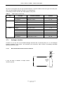
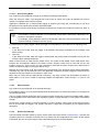
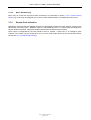
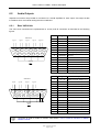
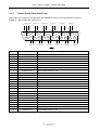
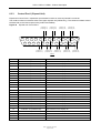
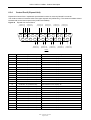
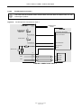
Control Port-1 on the base VAR4 unit has two types of global fault outputs; a changeover relay contact and a
set of relay contacts with resistors suitable for use in a monitored circuit such as that provided with Fire
Panels.
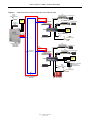
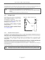
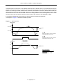
The diagram in Figure 20 shows the changeover
The diagram in Figure 21 illustrates the monitored
fault relay internal detail.
fault relay internal detail.
Figure 20
Fault Relay Output
Figure 21
ROUTER
CONTROL PORT-1
Monitored Fault Relay Output
ROUTER
CONTROL PORT-1
9
20
470 ohms
NC
NO
FAULT
RELAY
(SHOWN DE-ENERGISED)
22
COM
MONITORED
FAULT RELAY
CLOSED WHEN HEALTHY
(RELAY ENERGISED)
6k8 ohms
Relay Contact
(Closed=Healthy)
10
21
6.3.6
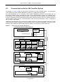
Fire Microphone Wiring Examples
6.3.6.1
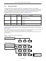
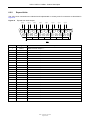
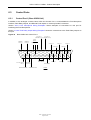
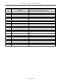
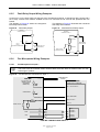
Fire Microphone on Input 1
L
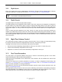
Figure 22
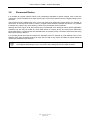
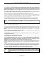
The LEDs must have suitable series resistors fitted; these are fitted as standard within the ASL
FMS range of product.
Fire Microphone Connections to Input 1
FROM V400 AUX
OUTPUT
+ SUPPLY
FIRE MIC
0V SUPPLY
ROUTER
ALL-CALL-ONLY LED
(NORMALLY FITTED
ON ZONEABLE
FIREMIC ONLY)
CONTROL PORT-1 ON BASE UNIT
PIN 11: ALL-CALL-ONLY-1
ALL-CALL-ONLY-LED
SPEAK NOW LED
PIN 23: SPEAK-NOW-1
SPEAK-NOW-LED
470
PIN 8: ALL-CALL-1
PTT
6k8
PIN 6: 0 V
PRESS-TO-TALK
INPUT-1
0V
AUDIO -
AUDIO
PIN1 AUDIO -
AUDIO +
PIN2 AUDIO +
DATA -
DATA
PIN5 DATA-
DATA +
PIN9 DATA+
FIRE MIC CONNECTIONS: INPUT 1
Issue: 03 complete, approved
Page 54 of 68