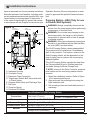
1
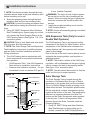
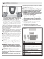
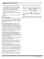
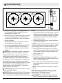
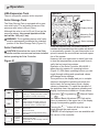
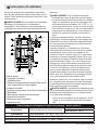
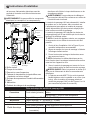
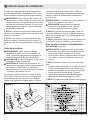
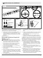
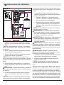
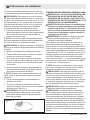
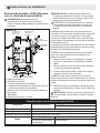
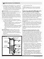
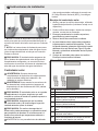
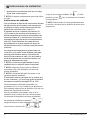
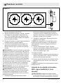
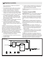
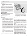
Operation
ists.
! NOTE: If there is some air accumulated,
open the air separator long enough to release
the air. Then run the system for a little while and
open it again to ensure that all of the air has
been removed.
• Temperature Gauges
The system is equipped with two temperature
gauges to monitor the temperature of the fluid
travelling to and from the Solar Collector Panels.
The color of the printing on the dial indicates
the direction of flow to assist in monitoring the
system:
• Red lettering = SP (from the Solar Collectors)
• Blue lettering = RT (to the Solar Collectors)
The range of the gauges is 70 - 300 °F (20 - 150
°C).
Solar Loop Expansion Tank
There is no specific operator action required.
HXA Pumping Station (If Applicable)
arning: CHECK THAT ALL VALVES ARE
W
ORIENTED IN THE APPROPRIATE DIRECTION BEFORE STARTING THESE INSTRUCTIONS. See Figure 19
Warning: The housing of the motor and any
uninsulated piping can be hot during operation.
To avoid burns, do not let bare skin touch hot
surfaces.
The circulation pumps on the Solar Pumping Station and the HXA Pumping Station are controlled
by the comparison of temperatures of the temperature probe in the Solar Storage Tank and the
temperature probe at Solar Collectors. The Solar
Controller turns the pumps On and Off and adjusts
the speed, of both, to maximize the efficiency of
the system and the result is a totally automated
system where periodic monitoring is all that is
required.
,
The Solar Controller will display the symbol
indicating that the pumps are On.
CAUTION: Both pumps should be running at
the same time, if only one pump is running discon-
nect power to the system and troubleshoot the
issue.
• Pressure Relief Valve
The pumping station is equipped with a pressure relief valve. The activation pressure of the
pressure relief valve is 29 psi (2 bar).
Although the valve is set for 29 psi (2 bar) as the
pressure release, the normal operation of the
unit will be 14.5 psi (1 bar).
Warning: The supplied pressure relief
valve must be permanently installed at the intended position of the solar pumping station.
• Check Valves
When the system is not operating, the Check
Valves in the pumping station prevent the uncontrolled circulation of the heat transfer medium. They are located in the Shut-off Ball Valves
in the supply and the return lines in each pumping station.
CAUTION: The shut-off ball valves must only
be activated by trained Operators. Failure to observe the flow direction can result in the check
valve working against the intended flow direction
and, as a result, blocking the flow and possibly
damaging the system.
They should only be opened manually (Figure
18) by adjusting the ball valves 45° clockwise,
from the open operating position, for filling and
draining the system or closed for maintenance
to prevent any flow of solution.
• Temperature Gauges
The system is equipped with two temperature
gauges to monitor the temperature of the water
travelling to and from the Solar Collector Panels. The color of the text on the dial indicates
the direction of flow to assist in monitoring the
system:
• Red lettering = SP (from the Solar Pumping
Station)
• Blue lettering = RT (to the Solar Pumping Station)
The range of the gauges is 70 - 300 °F (20 150 °C).
28
www.renewables.dimplex.com