1
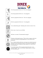
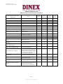
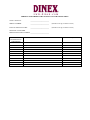
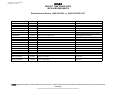
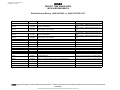
Perfect•Temp
Equipment Operation & Maintenance Manual
Revised July, 2007
INTERNATIONAL, INC.
WWW.DINEX.COM
800-523-9752
628-2 HEBRON AVE, GLASTONBURY, CT 06033
PERFECT-TEMP STATION COMMANDER CONTROLLER
OPERATION INSTRUCTIONS
Introduction
The PT-SC controller (Station Commander) is configured into two independent modules,
the Operator Module and the Power Module which are linked together by an
interconnecting, low-voltage cable.
The software, or programming information, is entered and stored in the operator module
which may be wall mounted or installed in a roll-in refrigerator bezel.
The electrical connection from the building electrical supply and the output to the
Perfect-Temp cart(s) are done within the power module which is available as either a
single cart version (Single Power Module) or a four (4) cart version (Quad Power
Module).
Programming Overview
The Station Commander Operator Module is capable of being programmed to facilitate
the following:
•
Program for up to eight (8) Perfect-Temp carts.
•
Automatic thermalization start for breakfast, lunch and dinner.
•
Ability to accept a Dinex start time for a Dinex cart at breakfast, lunch and dinner.
•
Independent thermalization cycle times for each meal.
•
Automatic “hold” cycle at the completion of the thermalization cycle. “Hold” cycles
can be customized for each meal, by selecting “hold” cycle duration, heat, and noheat sequencing.
•
Adjustable volume control for acknowledgement of programming entries and for
completion of the thermalization cycle.
•
Keypad entered pass codes for entry into the programming menu or for manual
starting of the thermalization cycle.
•
Programmable pass codes (2 levels).
Macintosh HD:Users:sbasley:Documents:Microsoft User Data:Saved Attachments:PT Station Commander Operating Instructions 09-06-2006.doc
Last Revision: 06 September 2006 MLB
Page 1 of 14
No meals programmed for this cart. This cart is unplugged.
No meals programmed for this cart. Cart is plugged in.
Meals are programmed for this cart. This cart is unplugged.
Meals are programmed for this cart. Cart is plugged in.
Cart is rethermalizing meal. Remaining time is shown in center of icon.
Meal is ready. Outer box area will blink.
Hold time is exceeded. Thermalization has stopped.
Warning or informational message. This icon does not appear on the main
screen, but accompanies message displayed as a result of main screen
interactions.
Error. Indicates that there has been a user entry error or that the requested
operation can not be performed at this time. This icon does not appear on
the main screen, but accompanies message displayed as a result of main
screen interactions.
Cart is being Stopped. This icon appears temporarily when a cart is
manually stopped. This icon will remain for approximately one minute
after disconnecting cart.
Macintosh HD:Users:sbasley:Documents:Microsoft User Data:Saved Attachments:PT Station Commander Operating Instructions 09-06-2006.doc
Last Revision: 06 September 2006 MLB
Page 2 of 14
Programming Number of Carts Displayed and Speaker Volume
1)
Press the “PROGRAM” key
2)
Display will prompt:
Select:
Program Meal Times
Configure Unit
3)
Use the “ “ keys to highlight “Configure Unit”.
4)
Press the “YES” key to select.
5)
Enter pass code “15037” on the keypad.
6)
Display will prompt:
Select:
System Setup
Set Meal Parameters
Set Passcodes
Set Time of Day
Reset
7)
Use the “ “ keys to highlight “System Setup”.
8)
Press the “YES” key to select.
9)
Display will prompt:
System Setup
Number of Carts:
Alarm Volume:
Key Click Volume:
8
On
On
10) Use the keypad to enter the number of carts to be displayed (1-8).
11) Use the “ “ keys to highlight the Alarm Volume Setting “LOW”.
12) Use the “ “ keys to change the Alarm Volume Setting.
13) Use the “ “ keys to highlight the Key Clicks Volume Setting “LOW”.
(Continued)
Macintosh HD:Users:sbasley:Documents:Microsoft User Data:Saved Attachments:PT Station Commander Operating Instructions 09-06-2006.doc
Last Revision: 06 September 2006 MLB
Page 3 of 14
14) Use the “ “ keys to change the Key Clicks Volume Setting.
15) Press the “SAVE” key to store the change(s).
16) Press the “CANCEL” key to exit programming.
Meal Parameters
The Station Commander operator module has the capability of programming the carts
under its control for different thermalization cycle lengths for each meal. This means that
the breakfast meal thermalization cycle could be less than the dinner and lunch cycles,
should this be desirable.
In addition, an automatic hold cycle can be programmed to supply intermittent heating
after the normal thermalization cycle is complete. This allows carts to be held for a
programmable period of time without significant loss of heat to hot food items.
The hold cycle is comprised of two parts, the “ready” time and “maintain” time. At the
completion of the thermalization cycle, the electrical power to the Perfect-Temp cart is
switched “off”. The duration of time that the power remains “off” is known as “ready”
time. When the “ready” time duration expires, electrical power to the Perfect-Temp cart
is switched “on”. The duration of time that the power remains “on” is known as
“maintain” time. At the expiration of the “maintain” time, the power again is switched
“off” for another “ready” time. This sequence continues until the total elapsed time of
both the “ready” and “maintain” time exceeds the programmed “hold” time.
When the duration of the “hold time” is exceeded, the Station Commander automatically
discontinues further activity with that particular cart and displays the “Hold Time
Exceeded” symbol.
Programming Meal Parameters
1)
Press the “PROGRAM” key
2)
Display will prompt:
Select:
Program Meal Times
Configure Unit
(Continued)
Macintosh HD:Users:sbasley:Documents:Microsoft User Data:Saved Attachments:PT Station Commander Operating Instructions 09-06-2006.doc
Last Revision: 06 September 2006 MLB
Page 4 of 14
3)
Use the “ “ keys to highlight “Configure Unit”.
4)
Press the “YES” key to select.
5)
Enter pass code “15037” on the keypad.
6)
Display will prompt:
Select: System Setup
Set Meal Parameters
Set Passcodes
Set Time of Day
Reset
7)
Use the “ “ keys to highlight “Set Meal Parameters”.
8)
Press the “YES” key to select.
9)
Display will prompt:
Therm
Breakfast
30
Lunch
30
Dinner
30
Late Tray
30
Hold
30
30
30
30
Maintain
02
02
02
02
Ready
02
02
02
02
10) Use the “ “ keys to highlight the parameter you would like to change.
11) Use the keypad to enter the new parameters.
12) Repeat steps 26-27 to update additional parameters
13) Press the “SAVE” key to store the change(s).
14) Press the “CANCEL” key to exit programming
Macintosh HD:Users:sbasley:Documents:Microsoft User Data:Saved Attachments:PT Station Commander Operating Instructions 09-06-2006.doc
Last Revision: 06 September 2006 MLB
Page 5 of 14
Pass Codes
Each operator module is equipped with three levels of pass codes to provide security and
prevent tampering with cart thermalization programming or initiation.
1)
The Master pass code allows entry into the system. The Master pass code number
is 15037.
2)
The Supervisor pass code is a 4-digit pass code that permits access to mealtime
programming. This code can be selected and changed at any time. See
Programming Pass Codes section.
3)
The User pass code is a 3-digit pass code and permits access to the manual start
function. As with the Supervisor code, this code can be selected and changed at any
time. See Programming Pass Codes section.
Programming Pass Codes
1)
Press the “PROGRAM” key
2)
Display will prompt:
Select:
Program Meal Times
Configure Unit
3)
Use the “ “ keys to highlight “Configure Unit”.
4)
Press the “YES” key to select.
5)
Enter pass code “15037” on the keypad.
6)
Display will prompt:
Select: System Setup
Set Meal Parameters
Set Passcodes
Set Time of Day
Reset
7)
Use the “ “ keys to highlight “Passcodes”.
(Continued)
Macintosh HD:Users:sbasley:Documents:Microsoft User Data:Saved Attachments:PT Station Commander Operating Instructions 09-06-2006.doc
Last Revision: 06 September 2006 MLB
Page 6 of 14
8)
Press the “YES” key to select.
9)
Display will prompt:
Change Passcodes
Supervisor: 4444
User
333
Note: These are the default factory settings.
10) Use the keypad to enter new pass codes.
11) Press the “SAVE” key to store the changes.
12) Press the “CANCEL” key to exit programming.
Programming Time of Day
Note: All programming is done in military time to reduce the chance of programming
errors.
1)
Press the “PROGRAM” key
2)
Display will prompt:
Select:
Program Meal Times
Configure Unit
3)
Use the “ “ keys to highlight “Configure Unit”.
4)
Press the “YES” key to select.
5)
Enter pass code “15037” on the keypad.
6)
Display will prompt:
Select: System Setup
Set Meal Parameters
Set Passcodes
Set Time of Day
Reset
(Continued)
7)
Use the “ “ keys to highlight “Set Time of Day”.
Macintosh HD:Users:sbasley:Documents:Microsoft User Data:Saved Attachments:PT Station Commander Operating Instructions 09-06-2006.doc
Last Revision: 06 September 2006 MLB
Page 7 of 14
8)
Press the “YES” key to select.
9)
Use the keypad to enter a new time.
10) Press the “SAVE” key to store the change(s).
11) Press the “CANCEL” key to exit programming
Resetting the Controller
Note: Resetting the controller will reset “Meal Parameters” to default factory settings
and remove all “Meal Times”
1)
Press the “PROGRAM” key
2)
Display will prompt:
Select:
Program Meal Times
Configure Unit
3)
Use the “ “ keys to highlight “Configure Unit”.
4)
Press the “YES” key to select.
5)
Enter pass code “15037” on the keypad.
6)
Display will prompt:
Select:
System Setup
Set Meal Parameters
Set Passcodes
Set Time of Day
Reset
7)
Use the “ “ keys to highlight “Reset”.
(Continued)
8)
Press the “YES” key to select.
Macintosh HD:Users:sbasley:Documents:Microsoft User Data:Saved Attachments:PT Station Commander Operating Instructions 09-06-2006.doc
Last Revision: 06 September 2006 MLB
Page 8 of 14
9)
Display will prompt:
Resetting the unit will
destroy all programming
information.
Do you wish to continue?
10) Press the “YES” key to complete the resetting process.
11) Press the “CANCEL” key to exit programming
Meal Times
The meal times programmed are the actual meal times that the Perfect-Temp cart is
expected to be ready for meal service.
When mealtime is programmed, the Station Commander will automatically calculated the
correct thermalization start time based upon the programmed length of the thermalization
cycle.
For example, if the Perfect-Temp cart is to be ready for meal delivery at 11:00 a.m., and a
thermalization cycle of 35 minutes is programmed. Then 11:00 is programmed as the
mealtime and the controller automatically starts the thermalization cycle at 10:25 a.m.
(11:00 minus the 35 minute thermalization cycle).
A Dinex cart may be programmed for any cart location for breakfast, lunch or dinner.
Some consideration should be given to the programming of the Dinexnd cart time. The
thermalization time for the cart and the amount of time needed to change out the carts
needs to be considered.
For example, if the thermalization time is 35 minutes and you need 5 minutes to get the
carts changed out, Then the Dinex cart meal time should be at least 40 minutes after the
first (35 minute thermalization cycle plus 5 minutes for changing carts).
Macintosh HD:Users:sbasley:Documents:Microsoft User Data:Saved Attachments:PT Station Commander Operating Instructions 09-06-2006.doc
Last Revision: 06 September 2006 MLB
Page 9 of 14
Programming Meal Times
1) Press the “PROGRAM” key
2) Display will prompt:
Select:
Program Meal Times
Configure Unit
3) Use the “ “ keys to highlight “Program Meal Times”.
4) Press the “YES” key to select.
5) Enter pass code “4444” on the keypad.
6) Display will prompt:
Select:
Program Meals
Copy Meals
7)
Use the “ “ keys to highlight “Program Meals”.
8)
Press the “YES” key to select.
9)
Display will prompt:
Select Cart:
12345678
10) Use the “ “ keys to highlight the cart you would like to program.
11) Press the “YES” key to select.
12) Display will prompt:
Breakfast
Lunch
Dinner
Meal
--:---:---:--
2cd Cart
--:---:---:--
(Continued)
Macintosh HD:Users:sbasley:Documents:Microsoft User Data:Saved Attachments:PT Station Commander Operating Instructions 09-06-2006.doc
Last Revision: 06 September 2006 MLB
Page 10 of 14
13) Use the keyboard to enter meal times. The cursor will automatically jump from
field to field. Use the “ “ keys for extra mobility. The “NO” key may be
used to remove existing meal times.
14) Press the “SAVE” key to store the change(s).
15) Press the “CANCEL” key to exit programming or repeat steps 6-14 for the next
cart.
Copy Meal Times
The “Copy Meals” command can be very convenient if multiple carts have the same
“Meal Times”. This command copies the meal times from one cart to another.
1)
Press the “PROGRAM” key
2)
Display will prompt:
Select:
Program Meal Times
Configure Unit
3)
Use the “ “ keys to highlight “Program Meal Times”.
4)
Press the “YES” key to select.
5)
Enter pass code “4444” on the keypad.
6)
Display will prompt:
Select:
Program Meals
Copy Meals
7)
Use the “ “ keys to highlight “Copy Meals”.
8)
Press the “YES” key to select.
(Continued)
Macintosh HD:Users:sbasley:Documents:Microsoft User Data:Saved Attachments:PT Station Commander Operating Instructions 09-06-2006.doc
Last Revision: 06 September 2006 MLB
Page 11 of 14
9)
Display will prompt:
Copy Cart Programming:
From: 1
12345678
To:
1
10) Use the “ “ keys to highlight the cart from which you would like to copy
“Meal Times”.
11) Use the “ “ key to move down to the next line.
12) Display will prompt:
Copy Cart Programming:
From: 1
To:
1
12345678
13) Use the “ “ keys to highlight the cart you would like to copy “Meal Times”
to.
14) Press the “YES” key to copy meal times.
15) Display will prompt:
Cart Copied.
Press Yes to Continue.
16) Press the “YES” key to continue.
17) Repeat steps 9-16 to copy information to additional carts.
18) Press the “CANCEL” key to exit programming.
Macintosh HD:Users:sbasley:Documents:Microsoft User Data:Saved Attachments:PT Station Commander Operating Instructions 09-06-2006.doc
Last Revision: 06 September 2006 MLB
Page 12 of 14
Manual Starting of Carts
Regardless of what has been programmed, any Perfect-Temp cart may be manually
started to begin thermalization at any time. The Station Commander display will confirm
that a Perfect-Temp cart has been properly plugged in.
1)
Press the “MANUAL” key.
2)
Enter pass code “333” on the keypad.
3)
Display will prompt:
Select Cart:
12345678
4)
Use the “ “ keys to highlight the cart you would like to manually start.
5)
Press the “YES” key to select.
6)
Display will prompt:
Select Meal:
Breakfast
Lunch
Dinner
Late Tray
7)
Use the “ “ keys to highlight the meal you would like to thermalize
8)
Press the “YES” key to start the meal.
9)
Repeat steps 3-5 until you have started all carts you need to start.
10) Press the “CANCEL” key to exit programming.
Macintosh HD:Users:sbasley:Documents:Microsoft User Data:Saved Attachments:PT Station Commander Operating Instructions 09-06-2006.doc
Last Revision: 06 September 2006 MLB
Page 13 of 14
Stopping Meal Thermalization
Warning!! Meals should be stopped at the controller prior to disconnecting cart.
Failure to do this will result in excess wear on cart plugs and receptacles.
Use the “ “ keys to highlight the cart you would like to stop.
Press the “CANCEL” key.
Display will prompt:
Do you want to stop this meal?
Press YES or NO.
Press the “YES” key to stop thermalization of meal.
Macintosh HD:Users:sbasley:Documents:Microsoft User Data:Saved Attachments:PT Station Commander Operating Instructions 09-06-2006.doc
Last Revision: 06 September 2006 MLB
Page 14 of 14
LAST REVISION 09-07-2006
MAINTAINED BY: MICHAEL BEILMAN
PERFECT TEMP SYSTEM
PREVENTATIVE MAINTENANCE SCHEDULE
RECOMMENDED WORK TO BE
PERFORMED
TIGHTEN ALL EXPOSED FASTENERS
EVERY
MONTH
NOTES
EVERY
6 MONTHS
TOP PLATE TO SIDE PANELS
X
BOTTOM PLATE TO SIDE PANELS
X
LEXAN DOOR TO HINGE SCREWS
X
TOP CORNER BUMPERS TO TOP
PLATE
X
HEATER PAD ATTACHMENT SCREWS
X
CASTER ATTACHMENT HARDWARE
X
GREASE CASTERS
USE APPROVED NSF GREASE, DOW
RTV 732
RETAINING PLUNGERS - INSPECT
COMPONENT USED TO RETAIN
SWITCH SHIELDS
X
HEATER PADS- INSPECT
VERIFY TIGHT AND SEALED
PROPERLY TO SUPPORT
X
HEATER PAD SWITCHES - INSPECT
BENT, LOOSE, NOT WORKING
X
CIRCUIT BREAKERS - INSPECT
EVERY
12
MONTHS
EVERY
24
MONTHS
X
X
TEFLON DOOR HINGE WASHERS INSPECT
LOWER HINGE POINT
X
TEFLON SWITCH SHIELD WASHERS
- INSPECT
LOWER HINGE POINT
X
DETAIL CLEAN USING SMALL
AMOUNT OF SOLVENT
X
DROP CORDS – REFRIGERATION
INSPECT TWIST LOCK AT END,
REPLACE AS NECESSARY
CART CONNECTOR – INSPECT
INSPECT TO VERIFY THAT
CONNECTION PINS ARE NOT BLACK
FROM ELECTRICAL ARCING. VERIFY
THAT SLOTS FOR TWIST LOCK ARE
IN ACCEPTABLE CONDITION
X
HEATER PADS
REMOVE, INSPECT PAD AND CART
CONNECTION, RE-SEAL, INSTALL
X
CASTERS
INSPECT OPERATION OF SWIVEL,
BRAKES, SWIVEL LOCK
X
HEATER PAD CENTER EXTRUSION
SUPPORTS
REMOVE SIDE PANELS, TIGHTEN
SCREWS, RE-ASSY
X
HEATER PAD INTERNAL WIRING INSPECT
FRAYING, HOT MARKS, LOOSE
WIRES, GROMMET FAILURE, SWITCH
AND CIRCUIT CONNECTIONS,
MOISTURE, RE-ASSY SIDE PANELS
X
Page 15
Macintosh HD:Users:sbasley:Desktop:PerfectTempOp&Maint2.doc
X
PERFECT TEMP THERM CART MAINTENANCE TRACKING SHEET
CART CAPACITY:
_________________________
SERIAL NUMBER:
_________________________
(Found on UL tag on interior of cart)
DATE OF MANUFACTURE:
_________________________
(Found on UL tag on interior of cart)
OPTIONAL CUSTOMER
DESIGNATED CART NUMBER _________________________
DATE
MAINTENANCE
PERFORMED
WORK PERFORMED
PARTS REQUIRED
Last revised 12-31-2002
Michael L. Beilman
PERFECT TEMP THERMALIZATION CART TROUBLE SHOOTING GUIDE
Symptom: One side of cart is not working.
1.
2.
3.
4.
5.
6.
7.
8.
9.
10.
On the refrigerator that the cart was connected to, there is a grey box on top of the
refrigerator that is about 11” X 10” X 6”. This is referred to as the “Power Module”.
There may be a circuit breaker that has popped out on this unit. Look at the left hand
side of the box. There are (4) electrical type switches/breakers. The breaker that you
want to look at has a white end.
If it has popped, it will be protruding out
approximately ” from the side of the box. Push this breaker back in to make it flush
with the box.
On the cart, over the heater pad control switches, there is a breaker similar to the one
on the “power Module” detailed above, except it has a rubber boot over it. Check to
see if these breakers have popped. There is one on each side of the cart, be sure to
specifically check the side that is not working. Push these breakers to be sure that
they are flush.
Turn OFF all of the switches on the cart.
Plug the cart into the refrigerator drop cord, outside of the refrigerator.
Perform a manual start. Any meal choice is adequate.
Begin turning on each heater pad level, one at a time. First the soup switch, then the
entrée. Turn it on and listen for a pop noise. Check the breaker on that side of the
cart to see if has popped out. Turn off the heater pad for that level and go onto the
next switch. Again, listen for a pop. You will only need to leave each switch on for
about 15 seconds. The objective is to find out what level in the cart has a short.
Mark the heater pad switch/level that caused the breaker to pop. This is usually done
by placing a short piece of tape over the switch. Turn this heater pad switch off.
Again be sure that this switch is marked.
Check the breaker on the Power Module (ref. item #1). Reset if required per the
instructions described in item #1.
Check the cart breakers (ref. item #2).
Reset if required per the instructions
described in item #2.
There may be several reasons as to why the breaker popped but the cause is most
likely the heater pad associated with that switch. Remove and replace the heater pad
as follows:
10.1. Verify that Cart is NOT PLUGGED INTO POWER SOURCE.
10.2. Obtain the following from the spare parts kit – screwdriver, heater pad,
silicone.
10.3. Remove the two Phillips head screws from the pad (one each side).
10.4. Remove the heater pad. The pad may be moved up and down slightly to help
in removal. Exercise caution not to damage the rubber boot behind pad. Pull
pad straight out towards you. DO NOT twist the pad.
10.5. Remove the excess dried up silicone from the aluminum support, adjacent to
the rubber boot on the cart.
10.6. Prepare the new pad for installation by applying a thin film of the silicone to the
round area on the back of the pad, near the two gold electrical pins. The
sealant is used to prevent moisture from making contact with the electrical
pins. Sealant on the electrical pins is not preferred.
10.7. Verify that the female pin holes in the rubber boot on the cart are aligned
vertically (up and down direction).
Macintosh HD:Users:sbasley:Documents:Microsoft User Data:Saved Attachments:Perfect Temp Thermalization Cart Troubleshooting Guide 123102[1].doc
Last revised 12-31-2002
Michael L. Beilman
10.8.
11.
Install the new pad buy sliding it over the boot. It should slide into place with
very little effort. If it is not sliding into place easily, remove it and again verify
that the female pin holes in the rubber boot are properly aligned. Continue
effort until pad easily slides into place.
10.9. Install removed Phillips head screws (ref item 10.2). Tighten snug.
10.10. Test: Verify that the breakers on the refrigerator and the cart are properly set
in per the instruction of items #1 and #2.
10.11. Test the cart per items #3 through #6.
Breakers pop again after above repairs. If the breaker pops again, there may a small
problem with the internal wiring of the system. If this is occurs, this will require a
certified technicians review and repair. Schedule a service company through Dinex
Parts and Service Group.
Dinex Parts and Service
1-800-523-9752 Press 9 at voice mail answering.
1-800-523-9752 X107
Dinex Engineering
1-800-523-9752 X174
Macintosh HD:Users:sbasley:Documents:Microsoft User Data:Saved Attachments:Perfect Temp Thermalization Cart Troubleshooting Guide 123102[1].doc
Revised 12-29-2003
By: Michael Beilman
PERFECT TEMP HEATER PAD HEAT SPECS
REF ENGINEERING DRAWING 0113415-1
0113415
HEATER: Pad-Soup, Perfect Temp
Where used: Perfect Temp Classic & Continental Thermalization Carts
115 VAC, 60 Hertz
40 +/- 5% Watts
Element Resistance: 330 ohms nominal, 347 ohms maximum, 297 ohms minimum
Thermostat:
Open on rise (turn off temp) at:
290° +/- 6°F
Close on fall (turn on temp) at:
Turn off Temp - 12°F (max)
Thermal Fuse: burn out at 363°F
0113416
HEATER: Pad-Side, Perfect Temp
Where used: Perfect Temp Continental Thermalization Carts
115 VAC, 60 Hertz
35 +/- 5% Watts
Element Resistance: 378 ohms nominal, 397 ohms maximum, 359 ohms minimum
Thermostat:
Open on rise (turn off temp) at:
263° +/- 6°F
Close on fall (turn off temp) at:
Turn off Temp - 12°F (max)
Thermal Fuse: burn out at 363°F
0113417
HEATER: Pad-Round, Perfect Temp
Where used: Perfect Temp Classic Thermalization Carts
115 VAC, 60 Hertz
110 +/- 5% Watts
Element Resistance: 120.2 ohms nominal, 126.2 ohms maximum, 114.2 ohms minimum
Thermostat:
Open on rise (turn off temp) at:
263° +/- 6°F
Close on fall (turn off temp) at:
Turn off Temp - 12°F (max)
Thermal Fuse: burn out at 363°F
0113418 HEATER: Pad-Rectangular, Perfect Temp
Where used: Perfect Temp Continental Thermalization Carts
115 VAC, 60 Hertz
75 +/- 5% Watts
Element Resistance: 175 ohms nominal, 185 ohms maximum, 167 ohms minimum
Thermostat:
Open on rise (turn off temp) at:
263° +/- 6°F
Close on fall (turn off temp) at:
Turn off Temp - 12°F (max)
Thermal Fuse: burn out at 363°F
Note: The temperatures shown are for the thermostat adjacent to the electrical heating element. Therefore,
the temperature on the exterior surface of the pad may be slightly lower (approximately 5 Deg.F) than this
specification. Also, the temperature will decrease around the perimeter of the pad due to the heat transfer
between the aluminum plate and the plastic base.
Macintosh HD:Users:sbasley:Documents:Microsoft User Data:Saved Attachments:PERFECT TEMP HEATER PAD HEAT SPECS 122903.doc
Created/Revised by: Michael Beilman
Last Revised: 09-13-2006
DINEX
PERFECT TEMP SPARE PARTS
WITH SUBCOMPONENTS
Dinex Parts and Service (888) 232-7645 or (800) 523-9752 X 107
Component
Part No.
Notes
Description
Switch/Breaker
0113337
Switch: 3-Position, 2 pole, 6 Amp
Switch to operate Heater Pads
Switch/Breaker
0113338
Switch: 2-Position, 1 Pole, 6 Amp
Switch to operate Heater Pads
Switch/Breaker
0115755
Switch: 3-Position Sealed, 2 Pole
Switch to operate Heater Pads
Switch/Breaker
0113399
Label: 3-Position Switch
Switch Label
Switch/Breaker
0113398
Label: 2-Position Switch
Switch Label
Switch/Breaker
0113339
Boot: Switch 15/32 - 32 Thread
Boot that is installed over exterior of switch arm
Seal that is installed between the switch and the
inside of upright switch extrusion
Switch/Breaker
0113324
O-Ring, 7/16 I.D., 0.09375 Thick
Switch/Breaker
7000087
Breaker: 20 Amp, Magnetic, -2 Series
Installed in the single
modules
p and quadppower
g
Switch/Breaker
7000062
Breaker: 20 Amp, Magnetic, -0 Series
extrusion
Switch/Breaker
0113392
Boot: Breaker, Circuit Breaker 3/8-32 Thread
Switch/Breaker
0113325
Label: Circuit Breaker
Installed over the exterior of the breaker
Breaker Label
Heater Pads/Pigtails
0113415
Heater: Pad, Soup, Perfect Temp
Used on Classic and Continental carts
Heater Pads/Pigtails
0113416
Heater: Pad, Side, Perfect Temp
Used on Continental Carts
Heater Pads/Pigtails
0113417
Heater: Pad, Round, Perfect Temp
Used on Classic Carts
Heater Pads/Pigtails
0113418
Heater: Pad, Rectangular, Perfect Temp
Used on Continental Carts
Heater Pads/Pigtails
0114695
Harness: 30 in. Pigtail
Heater Pads/Pigtails
0114565
Harness: Pigtail Adapter
Runs through heater pad support extrusion to main
wire harness
Used to splice to main harness from the heater pad
attach point
DINEX reserves the right to revise this document at any time. Please contact the Parts and Service department for the most recent prices and
availability
Macintosh HD:Users:sbasley:Documents:Microsoft User Data:Saved Attachments:Spare Parts List with S
Created/Revised by: Michael Beilman
Last Revised: 09-13-2006
DINEX
PERFECT TEMP SPARE PARTS
WITH SUBCOMPONENTS
Dinex Parts and Service (888) 232-7645 or (800) 523-9752 X 107
Notes
Component
Part No.
Description
Receptacle/Plug/Cord
0113343
Connector: Cart End, 4-Pin, w/ Gasket
Connector on cart for drop cord attach
Receptacle/Plug/Cord
0113340
Connector: Cart End, 5-Pin, w/ Gasket
Receptacle/Plug/Cord
0114397
Connector: Refrig. End, 4-Pin
Receptacle/Plug/Cord
0114396
Connector: Refrig. End, 5-Pin
Receptacle/Plug/Cord
7000018
Connector: Refrig. End, 5-Pin
Connector on cart for drop cord attach
Connector on end of drop cord assy. INCLUDES
all electrical components
Connector on end of drop cord assy. INCLUDES
all electrical components
Connector on end of drop cord assy. No Electrical
Components.
Included
Casing - Metal
Not available as a separate component
Included
Gasket
Not available as a separate component
Included
Clip, Retaining
Not available as a separate component
Receptacle/Plug/Cord
06802318
Cable: PT Cable Assy, Meltric 4-Pin
Receptacle/Plug/Cord
06802319
Cable: PT Cable Assy, Meltric 5-Pin
Entire drop cord assy from EC 300 controller to
inside of refrig.
Entire drop cord assy from power module to inside
of refrig.
06802581
J-Hook Kit
KIT - Used to hang drop cord up
Receptacle/Plug/Cord
Qty 2
0111728
Washer: 1/4 inch Stainless Steel
Qty 2
0652590
Nut: 1/4 - 20 Locking FBR Plated
Qty 1
06803839
J-Hook
Qty 1
06803840
Strap Cable #3225T25
Test Cords
Test Cords
(Revised 07-28 - 97)
0678308
Cord: Heater Pad Test
Qty 1
0114297
Harness: Pigtail, Spare
Qty 1
0114413
Cap: 15 Amp, 2 Place, 2 Wire, NEMA 1-15P
0678309
Cord: Cart Test, 5-Pin
FABRICATED FROM
New cord under development as Part Number
6111245 AKA Vendor designation BT2000
DINEX reserves the right to revise this document at any time. Please contact the Parts and Service department for the most recent prices and
availability
Macintosh HD:Users:sbasley:Documents:Microsoft User Data:Saved Attachments:Spare Parts List with S
Created/Revised by: Michael Beilman
Last Revised: 09-13-2006
DINEX
PERFECT TEMP SPARE PARTS
WITH SUBCOMPONENTS
Dinex Parts and Service (888) 232-7645 or (800) 523-9752 X 107
Component
Part No.
Notes
Description
Protects switches - NEED TO ASK IF BLACK OR
GREY
Protects switches - NEED TO ASK IF BLACK OR
GREY
Bumpers
0113400G
Bumper: Vertical (Grey)
Bumpers
0113401G
Bumper: Bottom, Corner (Grey)
Bumpers
0113400
Bumper: Vertical (Black)
Bumpers
0113401
Bumper: Bottom, Corner (Black)
Protects switches - NEED TO ASK IF BLACK OR
GREY
Protects switches - NEED TO ASK IF BLACK OR
GREY
Set included (2) bumpers
Bumpers
0114011-1
Bumper: Set, Top, Front Corners (Black)
Bumpers
0114011-2
Bumper: Top, Left Handle Bumper (Black)
Bumpers
0114011-3
Bumper: Top, Right Handle Bumper (Black)
Bumpers
0283600
Screw: Bottom Bumper 1/4-20x3/4 TR, S/S mch
Bumpers
0283400
Screw: Top Bumper 1/4-20 x3/4 FL, S/S, mch
Casters
7000074
Casters
7000094
Caster: 5 X 2, Rigid, Standard Bolt Pattern, 4-5108-459-2
Caster: 5 X 2, Swivel, Total Locking, Small Bolt Pattern,
4F8305C260071-AR
Casters
7000095
Caster: 5 X 2, Rigid, Small Bolt Pattern, 4F8305C260001-AR
Used to attach lower bumpers to bottom plate
Used to attach upper bumpers to top plate
Caste used o
Ca ts
e
e p oduct o
began.
Caster used to supercede older PT Carts fabricated
by Seco and Therma Systems. Small Bolt Pattern.
Caster used to supercede older PT Carts fabricated
by Seco and Therma Systems. Small pBolt Pattern.
Casters
7000080
Caster: 5 X 2, Swivel with Side Brake, 4-5109-459-2BRK3
began.
Casters
0113993
Caster: 5" Heavy Duty 2" Wide, Rigid
Limited Quantities Available
Casters
0113994
Caster: 5" Heavy Duty 2" Wide, Swvl
Casters
0114371
Caster: 5" Heavy Duty 2" Wide, Swvl w/Brake
Limited Quantities Available
Limited Quantities Available
DINEX reserves the right to revise this document at any time. Please contact the Parts and Service department for the most recent prices and
availability
Macintosh HD:Users:sbasley:Documents:Microsoft User Data:Saved Attachments:Spare Parts List with S
Created/Revised by: Michael Beilman
Last Revised: 09-13-2006
DINEX
PERFECT TEMP SPARE PARTS
WITH SUBCOMPONENTS
Dinex Parts and Service (888) 232-7645 or (800) 523-9752 X 107
Notes
Component
Part No.
Doors/Switch Shields
0678295
Shield: Switch, PT-16
Protects switches, hinged at top and bottom
Doors/Switch Shields
0678296
Shield: Switch, PT-20
Protects switches, hinged at top and bottom
Doors/Switch Shields
0678297
Shield: Switch, PT-24
Protects switches, hinged at top and bottom
Doors/Switch Shields
Description
0689885
Door: Assembly, PT-16
Qty 9
0114002
Nut: Binding Post, 3/16" Length
Qty 9
0114006
Washer: #12 Lock, Internal Tooth
Qty 1
0114012
Door: PT-16, Option
Qty 9
0114694
Screw: 8 - 32 X 1/2 Truss Head, Phillips, S/S
Qty 1
0678292
Hinge: PT-16, Door Option
Qty 1
0680069
Backer: Door, PT-16
Doors/Switch Shields
0684675
Door: Assembly, PT-20
Qty 11
0114002
Nut: Binding Post, 3/16" Length
Qty 11
0114006
Washer: #12 Lock, Internal Tooth
Qty 1
0114013
Door: PT-20, Option
Qty 11
0114694
Screw: 8 - 32 X 1/2 Truss Head, Phillips, S/S
Qty 1
0678293
Hinge: PT-20, Door Option
Qty 1
0680072
Backer: Door, PT-20
KIT/ASSEMBLY
FABRICATED, ref engr drawing
KIT/ASSEMBLY
Estimate
FABRICATED, ref engr drawing
DINEX reserves the right to revise this document at any time. Please contact the Parts and Service department for the most recent prices and
availability
Macintosh HD:Users:sbasley:Documents:Microsoft User Data:Saved Attachments:Spare Parts List with S
Created/Revised by: Michael Beilman
Last Revised: 09-13-2006
DINEX
PERFECT TEMP SPARE PARTS
WITH SUBCOMPONENTS
Dinex Parts and Service (888) 232-7645 or (800) 523-9752 X 107
Component
Part No.
Doors/Switch Shields
Notes
Description
KIT/ASSEMBLY
0681615
Door: Assembly, PT-24
Qty 13
0114002
Nut: Binding Post, 3/16" Length
Qty 13
0114006
Washer: #12 Lock, Internal Tooth
Qty 1
0114014
Door: PT-24, Option
Qty 13
0114694
Screw: 8 - 32 X 1/2 Truss Head, Phillips, S/S
Qty 1
0678294
Hinge: PT-24, Door Option
Qty 1
0680073
Backer: Door, PT-24
Doors/Switch Shields
0113441
Bolt:Top, Door/Switch Shield
Top hinge bolt
Doors/Switch Shields
0113440
Bolt: Bottom, Door/Switch Shield
Bottom hinge bolt
Doors/Switch Shields
0113335
Nut: Flange, Door/Switch Shield, 5/16-18
Doors/Switch Shields
0115465
Plunger: Stop, Door/Switch Shield
Used to attach above hinges to top/bottom
Installed on top plate. Used to hold shields and
doors open and closed
Doors/Switch Shields
0114694
Screw: Door, 8-32X1/2 TR, PH, S/S
Doors/Switch Shields
0113334
Washer: Teflon, 3/16 I.D. X 1/2 O.D.
Doors/Switch Shields
0114006
Washer: Locking, Star, #12 Lock internal tooth
Doors/Switch Shields
0114002
Nut: Door, Binding Post, 3/16 long
Handle
Estimate
FABRICATED, ref engr drawing
Used to attach Lexan door to inge extrusion
and door. Installed over the top of the hinge bolt
pin.
Used to attach Lexan door to inge extrusion
Used to attach Lexan door to inge extrusion
KIT
0682745
Handle:Kit, Current Handle
Qty 2
0113332
Nut: 1/4 - 20 Tubing
Qty 1
0676177
Handle: Tube, Perfect Temp
Handle
0688346
Handle:Kit, Rancho Los Amigos
Miscellaneous - Cart
0114291
Labels: "Heater Pad Out of Service"
Placed on heater pads by tray line or server
personnel when pad is bad
Miscellaneous - Cart
0297000
Adhesive: Silicone, Dow Corning 732 RTV, Clear 3 Ounce Tube.
General NSF approved caulking
Miscellaneous - Cart
0113484
Grease: Dielectric, Permatex 82325
General NSF approved grease
Miscellaneous - Cart
0113326
Screw: 1/4-20x1-1/2 FH, Socket
Misc screw
FABRICATED, ref engr drawing - Estimate
DINEX reserves the right to revise this document at any time. Please contact the Parts and Service department for the most recent prices and
availability
Macintosh HD:Users:sbasley:Documents:Microsoft User Data:Saved Attachments:Spare Parts List with S
Created/Revised by: Michael Beilman
Last Revised: 09-13-2006
DINEX
PERFECT TEMP SPARE PARTS
WITH SUBCOMPONENTS
Dinex Parts and Service (888) 232-7645 or (800) 523-9752 X 107
Component
Part No.
Notes
Description
Controller - Refurbished
06802304
EC-300(R) Refurbished Controller w/ External Battery Pack
Refrigerator Mounted Unit
Controller - Refurbished
06803438
Time Captain(R) Refurbished Controller Flush Mount
Refrigerator Mounted Unit
Controller - New
06803989
Station Commander Controller Flush Mount
Refrigerator Mounted Unit
Controller - Refurbished
06803991
Station Commander(R) Refurbished Controller Flush Mount
Controller
06803452
Overlay - Time Captain Controller
Refrigerator Mounted Unit
field.
Power Module
06803453
Opto Board Part # 5310103
Power Module
0115870
Power Supply Board
Mounted inside of power module over the top of the
12 volt converter
Mounted inside of power module under the Opto
board. Converts power to 12 Volts
Power Module
0117558
Contactor - 12 Volt
Transfer power from input to cart
Power Module
0117560
Breaker: 3 Amp
Mounted on the side of the Power Module
Power Module
06803097
Module: Perfect Temp Single Power
Power Module
06803095
Module: Perfect Temp Quad Power
Used to transfer power from source to cart
Used to transfer power from source to cart
DINEX reserves the right to revise this document at any time. Please contact the Parts and Service department for the most recent prices and
availability
Macintosh HD:Users:sbasley:Documents:Microsoft User Data:Saved Attachments:Spare Parts List with S