1
9. Upon seeing a solid flow of water from the drain tubing, and the cessation of the “gurgling” sound at the
drip cup, H (Fig. 7), close valve D (Fig. 7) then rapidly
apply compressed air or nitrogen into the to chamber
of the Model LP Dry Valve Actuator until the pressure
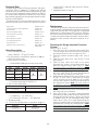
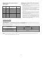
conforms to Table A levels as indicated on the air
pressure gauge. The Model LP Dry Valve Actuator
will close during this pressurizing process and the
water will stop flowing into the drip cup. At this point,
the pressure gauge which indicates push-rod chamber pressure (Fig. 7) will equalize to the available water supply pressure. Note: It may be necessary to
isolate the various pressure gauges in the trim during
system set-up by closing the ¼” 3-way valves (#68
Fig. 2) that they are connected to. During set-up,
pressure fluctuations may occur that can be potentially damaging to the gauges.
10. De-energize the solenoid valve(s). This is accomplished by resetting the solenoid-release pull station
and/or the detectors that were activated in Step #8
above. Note: All detection devices must be reset before the releasing/control panel can be reset.
11. Open valve F (Fig. 7). Open slightly the main valve
controlling water supply (Fig. 7) to the deluge valve,
closing drain valve B (Fig. 7) when water flows. Observe if water leaks through the ball drip valve, valve
G (Fig. 7), into the drip cup, H (Fig. 7). If no leak occurs, the seluge valve’s clapper is sealed. Open
slowly, and verify that the main valve controlling water
supply is fully opened and properly monitored.
12. Verify that valve A (Fig. 7) and valve F (Fig. 7) are
open.
13. Secure the handle of the Model B Manual Emergency
Station, valve D (Fig. 7), in the OFF position with a nylon tie (#64, Fig. 2).
7. Testing alarms — make sure that valve F (Fig. 7) is
open. Open valve C (Fig. 7) permitting water from the
supply to flow to alarm portion of the trim. Typical devices that are connected to this section of the trim are
pressure switches and/or a mechanical sprinkler
alarms (water motor). After testing has been completed, close this valve securely. Push in on the
plunger of ball drip valve G (Fig. 7) until all of the water
has drained from the alarm line.
8. Operational test — Open the Model B Manual Emergency Station, valve D (Fig. 7). Note: An operational
test will cause the deluge valve to openand flow water
into the sprinkler system.
9. Secure the Model B Manual Emergency Station,
valve D (Fig. 7), in the OFF position with a nylon tie
(#64, Fig. 2) after the deluge valve is reset.
Inspection and Testing
Draining Excess/Condensate Water from
the System
Testing the Model DDX Deluge Valve
without Flowing Water
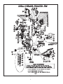
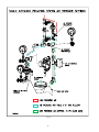
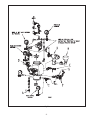
Refer to Fig. 7
1. Close the valve controlling water supply to deluge
valve and open the main drain valve B.
2. Verify that valve A is open, allowing water to enter the
push rod chamber.
3. Operate detection system – energize the solenoid
valve(s) by operating a detector or manual pull station.
4. Operation of the detection system will result in a sudden drop of water pressure in the push rod chamber.
5. Reset the detection system — reverse the operations
performed in step three above and then proceed according to the directions listed in the “Resetting the
Single Interlock Preaction System” section of this bulletin for resetting the Deluge Valve.
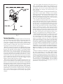
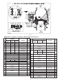
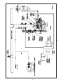
Refer to Figs. 2, 6, and 7.
1. Water supply — be sure the valve(s) controlling water
supply to the Deluge Valve are opened fully and
properly monitored.
2. Alarm line—be sure that valve F (Fig. 7) is opened
and remains in this position.
3. Other trimming valves — check that valve A (Fig. 7) is
open as well as all of the pressure gauge’s ¼” 3-way
valves. Valves C, D, and E (Fig. 7) should be closed.
4. Ball drip valve, valve G (Fig. 7)—make sure that valve
F (Fig. 7) is open. Push in on the plunger to be sure
the ball check is off its seat. If no water appears, the
deluge valve’s water seat is tight. Inspect the bleed
hole (see Fig. 7) on the underside of the deluge
valve’s push rod chamber for leakage.
5. System pneumatic pressure — check the Model LP
Dry Valve Actuator’s air pressure gauge (Fig. 7) and
water supply pressure gauge (Fig. 7) for conformance to Table A.
6. Releasing device - Model LP Dry Valve Actuator (Fig.
7). Verify that the outlet is not leaking water. Check the
Model LP Dry Valve Actuator’s air pressure gauge
(Fig. 7) for proper pressure settings. Verify that the
tubing line from the actuator is not pinched or
crushed, which could prevent proper operation of the
deluge valve.
Refer to Fig. 7
1. Close the main valve controlling water supply to deluge valve. Also, close valve A and open the main
drain valve B.
2. Open the condensate drain valve E until all of the water has drained. Close valve E. Note: Be sure not to
keep valve E open for an extended period of time because that will cause enough system air to bleed off,
thereby causing an undesirable activation of a trouble/alarm-annunciating device.
3. Close the main drain valve B. If system contains pressurized air, allow the air pressure to come back up to
specification. Open valve A first, and then open the
main valve controlling the water supply to the deluge
valve.
11.