1
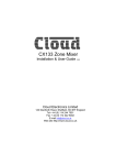
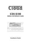
Sub Station 16-R
Installation & Operation
Manual V2.1
Cloud Electronics Limited
140 Staniforth Road, Sheffield, S9 3HF England
Tel +44 (0) 114 244 7051
Fax +44 (0) 114 242 5462
E-mail [email protected]
Web site http://www.cloud.co.uk
Sub Station 16-R: Installation and operation manual
1
Sub Station 16-R
Installation and operation manual
Contents
Section
16-07-02 V2.1
Page
1
Safety Notes...............................................................................2
2
General ......................................................................................2
3
The RJ45 Connection ................................................................2
4
Schematic Diagram....................................................................2
5
Installation ..................................................................................3
6
RH-8 Installation.........................................................................3
7
WP-8 Installation ........................................................................4
8
EMC Considerations ..................................................................6
9
Technical Specifications.............................................................7
10
General Specifications ...............................................................7
2
1
Sub Station 16-R: Installation and operation manual
Safety Notes
•
•
•
•
•
•
•
2
Do not expose this unit to water or moisture
Do not expose the unit to naked flames.
Do not block or restrict any air vent
Do not operate the unit in ambient temperatures above 35oC
There are no internal user adjustable parts. Do not remove covers.
Refer any servicing to qualified service personnel.
Do not replace the power transformer with any other type
For more detailed information refer to the rear of the manual.
General
The Sub Station 16-R increases the capacity of the Pump Station 16-R by up to sixteen RH-8 or
WP-8 remote control units. Each Pump Station 16-R can accommodate up to 15 Sub Station
16-R’s allowing a maximum system capacity of 256 remote control units. The system is wired
in a ‘daisy chain’ format; the cable for this comes supplied with each Sub Station 16-R.
The remote control units for use with the Sub Station 16-R are fitted with a headphone socket,
rotary source select switch and volume control. The RH-8 is designed to fit the majority of
exercise machines and can be wall mounted. The WP-8 is a dedicated wall-mounting version
of the RH-8 with provision for driving low power speakers.
Eight-core Category 5 (4-pair Cat- 5) cable should be used to wire each remote back to the Sub
Station 16-R. The RH-8 comes supplied with a 3m RJ45 patch cable that can be terminated
into a wall or floor mounted RJ45 socket (commonly used as part of a computer network).
The front panel controls on the Sub Station 16-R are reduced to a power switch with all
input/output terminations mounted on the rear panel. The unit can be located in a protected
area with the remote control units positioned in the most appropriate location.
3
The RJ45 Connection
The RJ45 plug is a compact 8-pole connector primarily designed for CAT5 cable.
Special tools are available making termination both easy and quick.
1) Strip approximately 1” of outer sheath from the cable.
2) Remove extraneous material such as plastic wrap or foil screen from the 8
exposed cores but do not strip their sheaths.
3) Cut the 8 exposed cores down so that when the cable is inserted into the RJ45 the outer core can be held by the plugs cable retention system.
4) Insert the 8 cores into the RJ-45 plug fully making sure that they are all
correctly arranged. Information on the correct arrangement of cores for the
RH-8 can be found in section 6 and the WP-8 details are in section 7.
5) Place the plug/cable assembly into the crimp tool and operate the mechanism.
6) You should now have a firmly connected cable assembly ready for installation.
The above notes are for guidance only: always follow the instructions supplied with the tool
4
Schematic Diagram
16-07-02 V2.1
Sub Station 16-R: Installation and operation manual
5
3
Installation
The Cloud Sub Station 16-R is suitable for mounting in a standard 19” equipment rack where it
will occupy two units of rack space. The Sub Station 16-R is 170mm deep, but a depth of
235mm should be allowed to clear the rear panel connectors. When possible, avoid positioning
the unit in close proximity to magnetic fields or equipment operating at a high temperature. The
Sub Station 16-R operates from an external plug-top transformer and a provision should be
made to plug this into a suitably positioned power socket. The Sub Station 16-R is fitted with an
RJ45 socket for each remote control unit; terminate using eight core category 5 cable (4 pair
Cat 5).
6
RH-8 Installation
When installing the RH-8 we suggest that an RJ45 data socket is
floor mounted adjacent to each one. Wire each data socket
individually back to the equipment rack pin to pin using CAT 5
cable. The RH-8 is fitted with an RJ45 compatible data socket
and supplied with a 3m patch cord to link to the floor mounted
data socket; this approach simplifies maintenance. The Sub
Station 16-R is fitted with an RJ45 socket for each remote control
unit.
Cable Information for Wiring the RH-8 to a Floor Socket
RH-8 (RJ45)
Sub Station 16-R (RJ45)
CAT 5*
Pin 8
Pin 8
Brown/White
Pin 7
Pin 7
White/Brown
Pin 6
Pin 6
Green/White
Pin 5
Pin 5
White/Blue
Pin 4
Pin 4
Blue/White
Pin 3
Pin 3
White/Green
Pin 2
Pin 2
Orange/White
Pin 1
Pin 1
White/Orange
*The CAT 5 colour is described as the dominant colour first with the tracer second
The RH-8 comes supplied with mounting accessories; allowing it to be mounted onto the frame
of an exercise machine or fixed to a flat surface such as a wall or bulkhead. When the RH-8 is
mounted onto the framework, two small nylon brackets should be fastened to the body of the
moulding using the nylon rivets provided. With the brackets in place, loop a nylon tie through
each of the two brackets and use these to securely fasten the RH-8 to the frame. To prevent
rotation on smooth surfaces, we suggest that self-amalgamating electrical insulating tape is
wound around the tube before the ties are fitted. The nylon brackets can be fitted in two
positions to suit the exercise machine.
FIT
BRACKET
HERE
FIT
BRACKET
HERE
16-07-02 V2.1
FIT
BRACKET
HERE
FIT
BRACKET
HERE
4
Sub Station 16-R: Installation and operation manual
When mounted to framework the RH-8 should be positioned at 45o (see left hand diagram
below), Ideally the RH-8 should also be positioned to one side of the user instead of directly in
front (See right hand diagram below)
When mounted directly on to a wall or perhaps the bulkhead of an exercise machine, it may be
preferable to hard wire a cable directly to the RH-8 using its internal screw terminals, a diagram
and wiring information for this are shown on the following page.
Cable for Hard Wiring an RH-8 to a Sub Station 16-R
Cable Information for Hard Wiring the RH-8
RH-8 (Screw Terminals) Sub Station 16-R (RJ45)
CAT 5*
Pin 1
Pin 8
Brown/White
Pin 2
Pin 7
White/Brown
Pin 3
Pin 6
Green/White
Pin 4
Pin 5
White/Blue
Pin 5
Pin 4
Blue/White
Pin 6
Pin 3
White/Green
Pin 7
Pin 2
Orange/White
Pin 8
Pin 1
White/Orange
*The CAT 5 colour is described as the dominant colour first with the tracer second.
7
WP-8 Installation
The WP-8 is a dedicated wall-mounting unit that has all of the
features of the RH-8 and provision for low power speakers.
The module is primarily aimed at scenarios such as tanning
suites and treatment rooms where users may wish to listen to
music. The WP-8 has two low impedance, low power speaker
outputs each with a different operation:
• The first is a normal low impedance speaker output.
• This second provides a similar low impedance output that is
disconnected when headphones are connected to the WP-8.
The WP-8 should be wired directly to the equipment rack
using unscreened ‘Category 5’ cable (4 pair CAT 5), an IDC
insertion tool will be required to connect the WP-8 to the CAT5 cable. Cable length should not exceed 100m (328ft).
16-07-02 V2.1
Sub Station 16-R: Installation and operation manual
5
Cable for Hard Wiring a WP-8 to a Sub Station 16-R
Cable Information for Wiring the WP-8
WP-8 (IDC)
Sub Station 16-R (RJ45)
CAT 5*
Pin 1
Pin 8
Brown/White
Pin 2
Pin 7
White/Brown
Pin 3
Pin 6
Green/White
Pin 4
Pin 5
White/Blue
Pin 5
Pin 4
Blue/White
Pin 6
Pin 3
White/Green
Pin 7
Pin 2
Orange/White
Pin 8
Pin 1
White/Orange
*The CAT 5 colour is described as the dominant colour first with the tracer second.
The following diagrams show how to wire either speaker output in stereo or mono.
Permanent Speaker Network (Stereo)
Permanent Speaker Network (Mono)
Switched Speaker Network (Stereo)
Switched Speaker Network (Mono)
The WP-8 will provide 150mW of power in stereo configuration and 300mW in mono into 8Ω
speakers. The impedance of the speakers is not critical however the unit will deliver more
power into speakers with an impedance of >8Ω.
Be vigilant when wiring the WP-8 since wiring errors can cause flawed operation. If a problem
is experienced, turn off the power, disconnect the WP-8 and double-check the wiring against
the WP-8 cable diagram on the previous page.
The Cloud WP-8 is designed to be wall mounted. The WP-8 is the same physical size as a
single UK electrical socket (13A Type) and can be mounted in the recessed back box provided
or be surface mounted in a standard 25mm deep housing.
The Cloud WP-8 is fitted with a 3.5mm stereo jack socket that will accept a pair of stereo
headphones. We recommend the use of headphones with 32-ohm impedance for example, the
Cloud CP-32.
16-07-02 V2.1
6
Sub Station 16-R: Installation and operation manual
It is also possible to obtain a line level output from the WP-8 by wiring it as follows:
Permanent Line Level Output (Stereo) Switchable Line Level Output (Stereo)
Permanent Line Level Output (mono)
Switchable Line Level Output (mono)
The output of the WP-8 can be used to drive a pair of powered speakers if extra volume is
required. The diagram below shows how this can be achieved.
Powered Speaker Output (mono)
8
Powered Speaker Output (stereo)
EMC Considerations
The Cloud Sub Station 16-R fully conforms to the relevant electromagnetic compatibility
(EMC) standards and is technically well behaved; you should experience no operational
problems and under normal circumstances, no special precautions need to be taken. If the
unit is used within close proximity to potential sources of HF disturbance such as high power
communications transmitters, radar stations and the like, the performance of the unit may be
reduced. Precautions can be taken when wiring the Pump Station 16-R, refer to its manual
for further details.
16-07-02 V2.1
Sub Station 16-R: Installation and operation manual
9
7
Technical Specifications
Headphone Output – via RH-8
Nominal output level
Optimum load impedance
Recommended headphones
100mW rms per channel with 32Ω load
32Ω
Cloud CP32
Headphone Output – via WP-8
Nominal output level
Optimum load impedance
Recommended headphones
100mW rms per channel with 32Ω load
32Ω
Cloud CP32
Speaker Output – via WP-8
Nominal output level
Optimum load impedance
10
150mW rms per channel with 8Ω load
>8Ω
General Specifications
Sub Station 16-R
Power consumption
Width
Height
Depth
Weight
20VA with approved external transformer
482.6mm (19.0”)
88mm (3.5”) – 1U
170.0mm (6.70”) + connectors
3.3kgs
Power Transformer
Output
Weight
15V AC 1.25A 18.5VA
0.52kg net
This Sub Station 16-R conforms to the following European EMC Standards:
BS EN 55103-1:1997
BS EN 55103-2:1997
This product has been tested for normal use in the commercial and light industrial environment. If the
equipment is used in controlled EMC environments, the urban outdoors, heavy industrial environments
or close to railways, transmitters, overhead power lines etc. the performance of the unit may be
degraded.
The Sub Station 16-R conforms to the following European electrical safety standard.
BS EN 60065:1998
The power transformers for the Sub Station 16-R conform to the following standards:
Power transformer for the UK market (Friwo 11.8367)
BS EN60742 + BABT
Power transformer for the European market (Friwo 11.8366)
EN60742 + EN60950
Power transformer for USA and Canada (SHOGYO A572710OT)
C-UL Approved
16-07-02 V2.1
8
Sub Station 16-R: Installation and operation manual
Safety Considerations and Information
When the mains switch is in the off ‘O’ position the Sub Station 16-R is disconnected from the
power transformer
CAUTION – Installation
Do not expose the unit to water or moisture
Do not expose the unit to naked flames.
Do not block or restrict any air vent
Do not operate the unit in ambient temperatures above 35oC
CAUTION – Servicing
The unit contains no user serviceable parts. Refer servicing to qualified service personnel. Do
not perform servicing unless you are qualified to do so.
Disconnect the power cable from the unit before removing the top or bottom panel
Only reassemble the unit using bolts/screws identical to the original parts
In the interest of continuing improvements Cloud Electronics Limited reserves the right to alter
specifications without prior notice.
Cloud Electronics Limited 140 Staniforth Road Sheffield S9 3HF England
Telephone +44 (0) 114 244 7051 Fax +44 (0) 114 242 5462 E-mail: [email protected]
16-07-02 V2.1