1
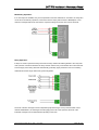
Unity DAU
Voice Alarm System
Installation and Maintenance Manual
Revision 1A − June 2005
UNITY DAU Installation & Maintenance Manual
Introduction
Voice Alarm (VA) systems are the quickest way to evacuate the public & staff from a building.
Following fire detection, automated messages control the flow of people in stairwells and corridors
allowing an orderly evacuation without panic. These messages are supplemented by spoken messages
from the fire service or management suite confirming the validity and need to leave the building.
This positive confirmation speeds evacuation and avoids the "false alarm" mentality reducing the risk of
death from fire.
Suitability
Voice Alarm systems are recommended for all public buildings and multi story buildings over four floors
by BS5588.
In public buildings it's not possible to fire drill the public, as they visit the premises infrequently, so
systems such as Voice alarms save valuable time in evacuating the building.
The use of phased messages in multi-story buildings prevents over-crowding in stairwells and at exits,
preventing secondary injuries. In phased evacuation, the floor in fire receives the evacuate message,
and the floor above & below receive an alert message, preparing them for evacuation.
In more complex scenarios the use of multiple alert and evacuate messages can be beneficial,
messages telling the evacuees they are going the right way, and messages asking people to make way
for people leaving evacuated areas. These additional messages can dramatically speed up the
evacuation especially in malls and large airport environments.
Product Overview
Unity has been developed to replace talking sounders in many voice alarm applications, and is available
in several forms. The DAU is a complete VA system in a single wall mount box which is complete with
messages, fire interface, dual 30W monitored amplifiers, power supply, monitored battery charger and
the ability to connect non monitored paging and music directly.
The DAU has been developed to draw the minimum of current in standby conditions and mutes the
music when the AC supply fails, the unit then draws 60mA quiescent current allowing the use of 3.2AH
commodity SLA batteries for full compliance with BS5839 part 8.
Connection to fire alarm systems could not be simpler; Unity DAU has independent Alert and Evacuate
inputs, which can be connected to reverse monitored sounder circuits directly. Once activated the fire
signals need to be de-latched by the reset input, for retrofit to systems with relays a protected 24V aux
supply is available.
The speaker lines are monitored using a low current DC system, which is continuous, and works with
the music playing. Faults reported are open, short and earth faults. Each speaker fitted to Unity DAU
must have a DC blocking capacitor fitted. The use of DC monitoring allows all cable types (MICC and
soft skin) to be used with the system.
Music sources can be plugged directly into the DAU, and the level of this can be set using a remote DC
volume control. When used with a paging microphone, the music ducks and restores gently after paging.
Document DCC UND 7001-01 Rev 1 June 2005
Page 2 of 17
UNITY DAU Installation & Maintenance Manual
Priorities
The Unity DAU has six fixed priorities for the inputs as follows:1.
Fire Microphone, this is the highest priority input on the system, designed to be used by
the controlling officer.
2.
Message Generator, this has three messages, all messages latch until reset from either
the front panel recessed button, or from the cancel button on the fire microphone or by the
RESET input from the Fire alarm input. Messages are prioritised in the following order:
a.
EVAC- Triggered from the fire alarm interface or from the fireman’s microphone, top
priority message.
b.
ALERT- Triggered from the fire alarm interface or from the fireman’s microphone,
second priority message.
c.
TEST- Triggered from the front panel or from the fireman’s microphone, this is the
lowest priority message.
3.
Page Input, this is the fifth priority input, designed for non-emergency functions such as
reception paging.
4.
Music Input, this is the lowest priority input and automatically selected when no other input
is exerting a priority, if not used turn the level control on the front panel fully anticlockwise.
Operation
The Unity DAU is fully automatic in operation; the only user controls available once the unit has been
commissioned are the front panel Reset and Test buttons. Pressing the test button will broadcast the
test message to the speaker circuits and latch until the Reset button is pressed.
The Unity DAU has fully compliant fault monitoring when correctly installed and commissioned, if any
status indicators are illuminated YELLOW (except the Message ACCESS Led) call service to investigate
the cause of the fault, this should be indicating a Sounder or Voice alarm fault on the Fire Alarm Panel.
Maintenance.
It is a requirement of BS5839pt8 that a maintenance agreement be in place for Voice Alarm systems,
the maintenance schedule should be as follows.
Weekly:
Broadcast the test message to all zones, and check speaker operation, microphones
should be checked for operation if fitted, record results in the site log.
Monthly:
Trigger the fire alarm system when the building is empty and check the Evacuate
message broadcasts, record results in the site log.
Quarterly:
Engineer Call to check system operation.
Yearly:
Engineer Call to check system operation and check Battery Health.
5 Yearly:
Engineer Call to check system operation and replace the batteries.
Document DCC UND 7001-01 Rev 1 June 2005
Page 3 of 17
UNITY DAU Installation & Maintenance Manual
Indications and Controls
Supply Section Indicators
AC
Indicates healthy AC mains available.
DC
Indicates the battery supply is available.
Fault
Either the AC supply or DC supply is unavailable, or a fuse has ruptured.
Amplifier Section Indicators (both channels are identical and independent)
Open
The DAU cannot see both end of line resistors for this amplifier channel.
Short
The DAU has detected a short on this amplifier channel.
Earth
The DAU has detected an earth fault on this amplifier channel.
Access Section.
Fire Mic
Lights green when the fireman’s microphone is activated.
Message
Lights when a stored message is playing, Green for test, Yellow for the Alert
Message and RED for the Evacuate message.
Paging
Lights green when the paging microphone is in use.
Music
Lights green when the music channel is open, (no other inputs in use).
Test
This is a recessed push button, pressing this starts the test message
broadcasting to the speakers.
Reset
This recessed push button cancels any message playing (this will not cancel
messages triggered from the fire alarm if the trigger is still active) the
message always plays to the end of the current cycle once Reset.
Fault Section.
General
This lights when the DAU detects any fault in its operation.
Fire Mic
Lights if there is any fault with the fireman’s microphone or cables to the
microphone.
Message
Lights if the message store in the DAU has detected a corruption.
Level Controls
Fire Mic
Sets the Level of the fireman’s Microphone, capped after commissioning.
Message
Sets the level of the stored messages in the Unity DAU, capped after
commissioning
Page
Sets the level of the paging microphone input to the DAU
Music
Sets the level of the music to the Speakers.
Document DCC UND 7001-01 Rev 1 June 2005
Page 4 of 17
UNITY DAU Installation & Maintenance Manual
Important Safety Information
This Equipment must only be installed and maintained by suitably skilled and competent
person.
This Equipment is defined as Class 1 in EN60065 (Low Voltage Directive) and must be
EARTHED.
CAUTION
INDOOR USE ONLY
WARNING
SHOCK HAZARDISOLATE BEFORE OPENING
WARNING
TO REDUCE THE RISK OF FIRE OR
ELECTRIC SHOCK, DO NOT EXPOSE THIS
UNIT TO RAIN OR MOISTURE
WARNING
WARNING
THIS UNIT MUST BE EARTHED
NO USER SERVICABLE PARTS
Each exchange unit requires a 3A spur, returning to a breaker clearly marked Voice Alarm
DO NOT TURN OFF. If the units are distributed around a site it is essential all units are on the
same mains phase, as they are classified TEN 230V, powering from different phases can
mean a 440V potential can be present in a unit during a major fault incident.
Anti-static handling guidelines
Make sure that electro-static handling precautions are taken immediately before handling
PCBs and other static sensitive components
Before handling any static-sensitive items, operators should get rid of any electrostatic charge
by touching a sound safety earth, such as a radiator. Always handle PCBs by their sides and
avoid touching any components. PCBs should be stored in a clean, dry place that is free from
vibration, dust and excessive heat.
Storing the PCBs in a suitable cardboard box will also guard them against mechanical
damage.
Document DCC UND 7001-01 Rev 1 June 2005
Page 5 of 17
UNITY DAU Installation & Maintenance Manual
Unpacking the Unit
Remove the Unity DAU from its packing, and check the contents against the following list:
1.
Unity DAU control Unit.
2.
Installation & maintenance manual (this document)
3.
Unity User Guide & logbook.
4.
Accessory pack with the following contents:a. Spare Mains Fuse.
b. Spare 5A blade battery Fuse.
c.
2.5mm AF Alan Key.
d. 4 off 18K 0.6W end of line Resistors.
e. Crimped Battery Link Lead.
f.
Black jumper header to Enable Fire Microphone Monitoring.
Using the HEX key supplied remove the front cover.
Verify the following items are present:
1.
2 off speaker connectors
2.
1 off 2 way fault connector
3.
2 off 4 way fire interface connectors
4.
1 off 8 way fire microphone connector
5.
1 off 5 way paging microphone connector
6.
1 off 2 way remote volume connector
If there are any Items missing please contact your supplier or Current Thinking Ltd, quoting
the unit serial number, and the name on the packing list enclosed so we can rectify the
situation.
Document DCC UND 7001-01 Rev 1 June 2005
Page 6 of 17
UNITY DAU Installation & Maintenance Manual
Preparation
Remove the front panel plate containing the circuit boards, this has a connection to the mains
transformer, which needs to be removed, Exercise static precautions to prevent damage to
the electronics, store the front panel assembly safely until the exchange is mounted and
cables have been attached.
Before mounting the DAU on the wall it is advisable to remove the cable knockouts. Decide
how the wiring will be brought into the panel and remove the required knockouts for cable
entry. If a knockout is removed fill the hole with a good quality cable gland. 18 knockouts are
provided, 8 on the top face from left to right, Speaker Network A, Speaker Network B, Fault,
Fire alarm Interface, Fire Microphone connection, Paging Microphone connection and finally
music input. These glands are repeated on the rear face. On the bottom face a single
knockout is for the incoming mains, this is repeated on the rear, mains SHOULD NOT enter
the box by any other hole. If additional holes are required, then the can be drilled as shown
below, taking care not to obscure the battery or PCB locations. Unused knockouts must be
left unopened to comply with the LVD, accidentally knocked out holes should be blanked off.
This work must be carried out prior to the re-installation of circuit boards.
Document DCC UND 7001-01 Rev 1 June 2005
Page 7 of 17
UNITY DAU Installation & Maintenance Manual
Mounting UNITY
Before mounting the DAU on the wall it is advisable to remove the cable knockouts. Decide
the best cable routes from the drawing below:
Speaker
Circuit A
Speaker
Circuit B
Fire
Interface
Fire
Mic
Paging Music
Mic
Safety
Earth
Connection
Mains
IN
The Unity DAU weighs 8KGs with batteries, so care should be taken to securely mount the
unit on stud walling.
Connecting UNITY
To comply with EMC (Electro Magnetic Compatibility) regulations and to reduce the risk of electrical
interference in the system wiring, we recommend the use of fire-resistant screened cables throughout
the installation.
All wiring should come into the enclosure via the knockouts provided and be fixed tidily to the relevant
terminals. For an overview of the connections required for the fire alarm interface, loudspeakers,
fireman’s microphone, paging/background music equipment and slave amplifiers, please refer to the
relevant sections later in this manual.
Note that correct cable glanding is essential and due regard should be paid to any system specifications
which demand a certain cable type (providing it meets the appropriate national wiring regulations).
PLANNING THE WIRING
All System wiring should be installed to meet the appropriate parts of BS5839-8 (1998), BS EN 60849
(1998) and BS 7671 (Wiring Regulations). Other national standards of installation should be adhered to
where applicable.
Do not test wiring with an insulation tester (Megger) with any equipment or speakers connected, as the
500 Volt test voltage will destroy these devices totally.
You must observe local wiring regulations. Do not run SELV and LV cables in the same enclosure
without adequate insulation between them.
Document DCC UND 7001-01 Rev 1 June 2005
Page 8 of 17
UNITY DAU Installation & Maintenance Manual
Mains Connection
>0.75mm 2 <2.5mm 2
3A
M a in
Distr ibu tio n
Bo ar d
UNITY
>3mm
Each Unity DAU requires a 3A spur, returning to a breaker clearly marked “Voice Alarm DO NOT
TURN OFF”. If the units are distributed around a site it is essential all units are on the same mains
phase, as they are classified TEN 230V, powering from different phases can mean a 440V potential can
be present in a unit during a major fault incident.
Batteries
The Unity DAU requires 2 number 12V 3.2AH sealed lead acid batteries to provide backup power in the
event of mains failure as defined in BS5839pt8 for 24 hours standby and 30 minutes operation.
For 72hour standby and 1 hour operation 2 number 12V 17AH batteries are required, these will need to
be fitted in an external battery enclosure, the monitored charger in the Unity DAU is capable of charging
and monitoring these batteries.
Safety Information:
Sealed Lead acid batteries contain sulphuric acid which can cause burns if
exposed to the skin, the low internal resistance of these batteries means large
currents will flow if they are accidentally short circuited, causing burns and a risk
of fire- exercise caution when handling batteries.
Power Up Procedure:
Always apply mains power before connecting batteries, do not commission
Unity DAU on batteries, as the high inrush current required by the power supply
may rupture the battery fuse.
Always connect the Positive (Red +) terminal first.
Power Down Procedure
Disconnect the batteries before removing the mains power; always remove the
negative (Black – terminal) first.
Connections
Document DCC UND 7001-01 Rev 1 June 2005
Page 9 of 17
UNITY DAU Installation & Maintenance Manual
Speaker Circuits
Unity has two speaker Circuits, A & B. to fully comply with the requirements of EN60849 the speakers
should be wired in an interleaved pattern, so if one circuit fails messages can still be heard in the areas
covered (note it is accepted practice to only place one speaker in an office, as long as the connecting
corridor is on the other circuit).
Each output of UNITY can support 30W of speakers, this is typically five 6W speakers, ten 3W speakers
or twenty 1.5W Speakers.
6W speakers are generally fitted in noisy offices or reception areas, 3W speakers are usually used in
corridors, and 1.5W speakers in small rooms or open plan offices.
Caution Speaker circuits carry 100V AC
Disconnect before servicing to prevent Shock hazard.
Speaker Circuits on Unity are DC monitored.
Suitable speakers for Unity MUST have a thermal fuse to disconnect the speaker if it is in the
area in fire and a DC blocking capacitor fitted, typically the capacitor is 2.2uF 250V DC.
The wiring goes through each speaker, and in the last speaker the end of line resistor. Each circuit can
have 2 spurs, the DAU is provided with two end of line resistors per circuit, both must be fitted to avoid
faults being shown on the panel. If only one spur is used per circuit, one resistor resides in the panel;
one resistor resides in the last speaker on the circuit.
Before connecting the speaker lines to UNITY count the number of speakers and note the tapping they
are set at, (most manufacturers will supply speakers at the maximum tapping, or at the half power
tapping) this value should not exceed the 30W rating of the UNITY DAU for a single circuit.
Document DCC UND 7001-01 Rev 1 June 2005
Page 10 of 17
UNITY DAU Installation & Maintenance Manual
It is desirable to have an impedance meter available (this measures the AC load that the UNITY DAU
sees). The measurement on the impedance meter should not be lower than 330 Ohms at 1KHz.
To work out the load from the impedance meter reading use the following equation:
P=10,000/Z
Where P is the power the amplifier sees, and Z is the reading in Ohms on the impedance meter.
Note!
Once the speaker lines are tested, record the results and the location of the end
of line devices in the User Log book supplied.
The lines should now be checked for the DC resistance between cores, this should read 9K Ohms if the
wires from the DAU to the end of lines are complete.
The speaker lines should also be tested between each core and earth, this should be in excess of 100K
Ohms, if not check the cabling, record the results in the user logbook
Speaker cables must be earthed to the safety earth connection point (see earlier in this manual);
preferred types are screened soft skin cables such as FP200 although MICC can be used.
Cable Length Chart
The following table shows the maximum cable run to achieve a drop of no more than 1dB as required by
BS5839 pt 8, the table also takes into account high frequency losses which prevent systems performing
to the requirements of BSEN60849. This means the system needs to achieve a common intelligibility
scale value equivalent to 0.5 STI (speech transmission index), this requires a bandwidth of 200Hz to
7KHz
Cable Type &
Gauge
Maximum Cable Length
10W Load
20W Load
30W Load
1mm Soft Skin
1500M
750M
380M
1.5mm Soft Skin
2000M
1000M
500M
2.5mm Soft Skin
4000M
2000M
1000M
1mm MICC
300M
200M
100M
1.5mm MICC
500M
250M
150M
2.5mm MICC
700M
300M
200M
Note MICC has shorter runs for the same cross section area due to the higher load capacitance of the
cable and the effect this has on high frequency signals.
Document DCC UND 7001-01 Rev 1 June 2005
Page 11 of 17
UNITY DAU Installation & Maintenance Manual
Fire Microphone Connections
The Unity DAU is designed to work with the ALFM1 fire microphone, which is connected Pin for Pin as
described below:
Note in each block the connections are reversed, on the ALFM1 the Au- pin is on the top, on the Unity
DAU the Au- pin is at the bottom of the block.
The DAU is shipped as standard with the monitoring of the Fire Microphone DISABLED- to enable the
monitoring fit the jumper supplied in the accessory pack as shown below:
Link fitted to
enable monitoring
The level of the Fire Microphone can be independently adjusted using the front panel recessed control
marked “FIRE MIC”, the fire microphone is always the top priority and mutes all other inputs.
Document DCC UND 7001-01 Rev 1 June 2005
Page 12 of 17
UNITY DAU Installation & Maintenance Manual
Fire Alarm Interface
The Unity DAU has been designed to connect to virtually any fire alarm system form simple
conventional systems, to complex analogue addressable loop systems.
The minimum fire alarm interface as defined by 5839pt8 is a monitored signal from the fire panel for
evacuate, a de-latch signal on reset or silence (Reset on the DAU) and a signal from the Voice Alarm to
the fire alarm control and indicating equipment signalling a fault. The interface monitoring is the
responsibility of the fire alarm system, and this is usually achieved by using sounder driver outputs from
a conventional panel, or monitored sounder interfaces on an addressable loop.
The inputs to Unity are opto-isolated, and are designed for direct connection to polarised sounder drive
outputs, in the normal monitored state, Unity expects to see between 0V and –33V on the inputs (meter
black(-) lead on Alert- or Evac -, meter red(+) lead on Alert+ or Evac +), and between +8V and +33V to
trigger a message. Once triggered the inputs latch, Evacuate always over-rides Alert. If the alert input is
not used, simply omit all connections, as it is the fire alarm, which monitors this link.
To silence messages the reset connection must have +10 to +33V applied, this can be done from a
relay which closes on fire panel reset or silence as shown below; the fire trigger (Alert or Evac) must be
removed for reset to work.
The Fault output must be connected to the fire alarm control and indicating equipment to provide a fault
sounder in the event of a fault with the DAU, otherwise an external fault sounder must be provided to
comply with BS5839pt8.
NOTE!
MESSAGES WILL ALWAYS PLAY TO THE END OF THE CURRENT CYCLE
WHEN RESET, THIS IS A REQUIREMENT, NOT A FAULT
Typical connections:
In this scheme, Alert and Evac require a sounder circuit drive to trigger the message, and the Evac
signal end of line is in series with the fault relay of Unity, If Unity detects a fault the relay opens,
removing the sounder circuit end of line and indicating a sounder fault on the fire alarm system.
Alternatively the fault input can be wired via a monitored input module to the fire alarm panel.
Document DCC UND 7001-01 Rev 1 June 2005
Page 13 of 17
UNITY DAU Installation & Maintenance Manual
Momentary Operation
If no reset output is available, and you have permission from the authorities or consultant, the Unity DAU
can be set for momentary operation, however this will not comply with the word of BS5839pt 8. In this
mode the messages will sound when there is a positive voltage across the Alert or Evac terminals.
Relay Operation
If relays are used to operate the Unity DAU then the relay modules should be glanded to the Unity DAU
case (note the connections between the relay contacts and the Unity control board will not be monitored
so the integrity of this wiring should be mechanically protected), again permission from the controlling
authorities should be sought before using this arrangement.
The level of the fire messages can be independently adjusted using the front panel recessed control
marked “MESSAGES”, the messages Override paging and music when operated, the level of the
individual messages can be altered before uploading to the DAU.
Document DCC UND 7001-01 Rev 1 June 2005
Page 14 of 17
UNITY DAU Installation & Maintenance Manual
Page Input
The paging input is an unmonitored input, at line level and the PTT line is connected to 5V to operate.
Once operated paging will mute the music input, once paging is complete the music will return gently.
The Ptt line goes to 5V when either the Fireman’s microphone or message generators are in use, the
Unity desk microphone uses this signal to light the busy LED on the microphone.
The Unity UNDM1 provides a complete solution to paging applications, and contains a chime generator,
microphone pre-amplifier and signal limiter to prevent clipping of the DAU and corrects for poor
microphone technique. The UNDM1 provides busy indication and first come first served logic for
cascading microphones.
Unity Microphone connections:-
rd
Using 3 Party Microphones.
Third party microphones can be used with Unity as long as they can provide a volt free Ptt contact, and
a balanced line level (0dBV) audio output. A 24V 100mA feed is available on the page connector to
provide power to an external microphone pre-amplifier to boost signals from microphone to line level.
Note: the Unity DAU does not contain a chime generator, and the microphone used must provide
this if required.
The level of the paging microphone can be independently adjusted using the front panel recessed
control marked “PAGE”
Document DCC UND 7001-01 Rev 1 June 2005
Page 15 of 17
UNITY DAU Installation & Maintenance Manual
Music Input
The music input is via a stereo pair of phono connectors, the Unity DAU is mono in operation, and the
Left & Right signals are mixed together in the DAU. If a mono line signal is required, this can be
provided to either input.
Music is automatically muted when mains fails in line with BS5839pt8 to preserve battery life.
The level of the paging microphone can be independently adjusted using the front panel recessed
control marked “MUSIC”.
NOTE!
If music is to be broadcast on the Unity DAU an appropriate PRS Licence should be obtained
within the UK.
The level of the music can be remotely adjusted using the Unity VC remote pot; this should be wired
across the two-way header, and the disable music jumper on the control board removed.
Remove to enable
remote Volume
Document DCC UND 7001-01 Rev 1 June 2005
Page 16 of 17
UNITY DAU Installation & Maintenance Manual
Technical Specification
POWER SUPPLY AND CHARGER
AC input
Internal power supply
Supply & battery monitored
Protection
Temperature compensation
Battery size and type
Mains fuse
Battery fuse
Max Battery Charge current
230Va.c +/- 10% 50/60Hz
30VDC
Open, Short, Fuses
Deep discharge, Short, Thermal
YES
2 x 12V 3.2AHr VRLA connected in
series
240V 2A HRC ceramic 20mm
Compliant with IEC (EN60127 Pt2)
5AF 24V Blade Fuse
1.1A
INPUTS
BGM
Sensitivity
Remote Control Range
Remote Pot Value
-6dBV to +2dBV
30dB (short for max volume, open to
mute)
10KΩ
Sensitivity
Ptt Type
Power
-6dBV to +4dBV
5V to access
+24V nominal 100mA self-resetting fuse
PAGE
Fire Interface
Inputs
3 off isolated +12V to +33V (Alert,
Evacuate, Reset)
1 Relay (open on fault) 30V 1A Max
+24V nominal 100mA self-resetting fuse
Outputs
Power
Fire Microphone
Audio Sensitivity
Control Inputs
0dBV Balanced Line
4 off Monitored triggers (PTT, MSG1,
MSG2, CNCL) 1.8V rest 5V active.
+24V nominal 100mA self-resetting fuse
Power
SPEAKERS
Circuits
Level
Bandwidth
Distortion
2 off 30W each
100V RMS (+40dBV)
80Hz to 18KHz (-3dB full power)
0.1% 20W 27.6V
1% 30W 26V
DC end of line (9KΩ expected)
Open, Short, Earth
Short, Open, Thermal, DC offset
Monitoring
Fault indication
Protection
The Unity DAU is designed and manufactured in the UK by:
Current Thinking Ltd,
Unit 91 Silver Briar
Enterprise Park East,
Sunderland,
SR5 2TQ.
www.current-thinking.com
[email protected]
WEEE
Compliant
Product
Document DCC UND 7001-01 Rev 1 June 2005
Page 17 of 17