1
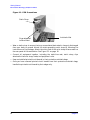
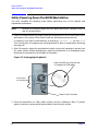
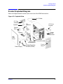
HP VISUALIZE B2000 UNIX® Workstations
Parts Removal/Replacement Guide
Manufacturing Part Number: HP Part No. A5983-90060
Edition E0100
© Copyright 2000 Hewlett-Packard Company
Notice
UNIX is a registered trademark in the United States and other
countries, licensed exclusively through X/Open Company Limited.
The information contained in this document is subject to change without
notice.
Hewlett-Packard assumes no responsibility for the use or reliability of its
software on equipment that is not furnished by Hewlett-Packard.
This document contains proprietary information that is protected by
copyright. All rights reserved. No part of this document may be
photocopied, reproduced or translated to another language without the
prior written consent of Hewlett-Packard Company.
HEWLETT-PACKARD WARRANTY STATEMENT
HP PRODUCT
REFERENCE
HP VISUALIZE B2000 Workstations
Warranty and Services/Support Booklet,
Part Number A5014-90140 (E1199)
The warranty statement shipped with your product supersedes any and
all previous workstation Warranty Statements for the Hewlett-Packard
Workstations specified herein. Note: This Parts-Only Base Warranty is
offered only in the US; for country-specific warranties, please contact
your HP country sales representative.
2
Year 2000 Compliance
This HP Year 2000 Warranty is in addition to the HP Standard
Commercial Warranties contained in Exhibit E16, HP Terms and
Conditions of Sale and Service. HP warrants that each HP hardware,
software, and firmware Product delivered under this HP Year 2000
Warranty will be able to accurately process date data (including, but not
limited to, calculating, comparing, and sequencing) from, into, and
between the twentieth and twenty-first centuries, and the years 1999
and 2000, including leap year calculations, when used in accordance with
the Product documentation provided by HP (including any instructions
for installing patches or upgrades), provided that all other products (e.g.
hardware, software, firmware) used in combination with such HP
Product(s) properly exchange date data with it.
If the Specifications require that specific HP Products must perform as a
system in accordance with the foregoing warranty, then that warranty
will apply to those HP Products as a system, and Customer retains sole
responsibility to ensure the Year 2000 readiness of its information
technology and business environment. The duration of this warranty
extends through January 31, 2001. The remedies available under this
warranty will be defined in, and subject to, the terms and limitations of
the warranties contained in HP’s standard commercial warranties. To
the extent permitted by local law, this warranty applies only to branded
HP Products and not to products manufactured by others that may be
sold or distributed by HP. This HP Year 2000 Warranty applies only to
HP Products shipped after the effective date, July 01, 1998, of this
warranty. Nothing in this warranty will be construed to limit any rights
or remedies provided elsewhere in the HP Terms and Conditions of Sale
and Service with respect to matters other than Year 2000 compliance.
RESTRICTED RIGHTS LEGEND.
Use, duplication, or disclosure by the U.S. government is subject to
restrictions as set forth in subdivision (c) (1) (ii) of the Rights in
Technical Data and Computer Software Clause in DFARS 252.227.7013.
Hewlett-Packard Co., 3000 Hanover St., Palo Alto, CA 94304.
3
4
Contents
1. Getting Started
Safety Warnings. . . . . . . . . . . . . . . . . . . . . . . . . . . . . . . . . . . . . . . . . . . . . .9
Electrostatic Discharge (ESD) Precautions . . . . . . . . . . . . . . . . . . . . . . . .9
Replacement Part Kit Contents . . . . . . . . . . . . . . . . . . . . . . . . . . . . . . . .11
Required Tools . . . . . . . . . . . . . . . . . . . . . . . . . . . . . . . . . . . . . . . . . . . . . .11
Safely Powering Down the B2000 Workstation . . . . . . . . . . . . . . . . . . . .12
Product Exploded Diagram . . . . . . . . . . . . . . . . . . . . . . . . . . . . . . . . . . . .13
2. Parts Replacement Procedures
Front Bezel and Left Side Panel . . . . . . . . . . . . . . . . . . . . . . . . . . . . . . .15
Opening the Front Bezel . . . . . . . . . . . . . . . . . . . . . . . . . . . . . . . . . . . .15
Closing the Front Bezel . . . . . . . . . . . . . . . . . . . . . . . . . . . . . . . . . . . . .16
Left Side Panel . . . . . . . . . . . . . . . . . . . . . . . . . . . . . . . . . . . . . . . . . . . .16
Memory DIMMs . . . . . . . . . . . . . . . . . . . . . . . . . . . . . . . . . . . . . . . . . . . .18
Installing Memory . . . . . . . . . . . . . . . . . . . . . . . . . . . . . . . . . . . . . . . . .18
Removing Memory DIMMs . . . . . . . . . . . . . . . . . . . . . . . . . . . . . . . . . .21
Displaying the Current Memory Configuration . . . . . . . . . . . . . . . . . .23
PCI I/O Card(s) . . . . . . . . . . . . . . . . . . . . . . . . . . . . . . . . . . . . . . . . . . . . .25
Removing I/O Cards . . . . . . . . . . . . . . . . . . . . . . . . . . . . . . . . . . . . . . . .26
Installing I/O Cards . . . . . . . . . . . . . . . . . . . . . . . . . . . . . . . . . . . . . . . .28
CD Drive. . . . . . . . . . . . . . . . . . . . . . . . . . . . . . . . . . . . . . . . . . . . . . . . . . .29
Removing a CD Drive. . . . . . . . . . . . . . . . . . . . . . . . . . . . . . . . . . . . . . .29
Installing a CD Drive . . . . . . . . . . . . . . . . . . . . . . . . . . . . . . . . . . . . . . .31
Floppy Drive. . . . . . . . . . . . . . . . . . . . . . . . . . . . . . . . . . . . . . . . . . . . . . . .37
Installing a Floppy Disk Drive . . . . . . . . . . . . . . . . . . . . . . . . . . . . . . .37
Removing the Floppy Drive . . . . . . . . . . . . . . . . . . . . . . . . . . . . . . . . .41
Verifying the Floppy Drive Configuration. . . . . . . . . . . . . . . . . . . . . . .44
5
Contents
Hard Disk Drive . . . . . . . . . . . . . . . . . . . . . . . . . . . . . . . . . . . . . . . . . . . .
Installing a Hard Disk Drive . . . . . . . . . . . . . . . . . . . . . . . . . . . . . . . .
Removing a Hard Disk Drive . . . . . . . . . . . . . . . . . . . . . . . . . . . . . . . .
Configuring a Hard Disk Drive as a File System . . . . . . . . . . . . . . . .
45
45
49
52
Power Supply . . . . . . . . . . . . . . . . . . . . . . . . . . . . . . . . . . . . . . . . . . . . . . 57
Removing the Power Supply. . . . . . . . . . . . . . . . . . . . . . . . . . . . . . . . . 57
Installing the Power Supply . . . . . . . . . . . . . . . . . . . . . . . . . . . . . . . . . 61
Voltage Regulator Modules (VRMs) . . . . . . . . . . . . . . . . . . . . . . . . . . . . 63
Removing VRMs . . . . . . . . . . . . . . . . . . . . . . . . . . . . . . . . . . . . . . . . . . 63
Installing VRMs . . . . . . . . . . . . . . . . . . . . . . . . . . . . . . . . . . . . . . . . . . 65
System Board . . . . . . . . . . . . . . . . . . . . . . . . . . . . . . . . . . . . . . . . . . . . . . 66
Removing the System Board . . . . . . . . . . . . . . . . . . . . . . . . . . . . . . . . 66
Installing the System Board. . . . . . . . . . . . . . . . . . . . . . . . . . . . . . . . . 68
Fans (I/O and System Board Fan) . . . . . . . . . . . . . . . . . . . . . . . . . . . . . .
Removing the I/O Fan . . . . . . . . . . . . . . . . . . . . . . . . . . . . . . . . . . . . . .
Installing the I/O Fan . . . . . . . . . . . . . . . . . . . . . . . . . . . . . . . . . . . . . .
Removing the System Board Fan . . . . . . . . . . . . . . . . . . . . . . . . . . . . .
Installing the System Board Fan . . . . . . . . . . . . . . . . . . . . . . . . . . . . .
72
72
75
75
76
LCD Display with Power Switch and Display Cable . . . . . . . . . . . . . . . 77
Removing the LCD Display/Power Switch Assembly . . . . . . . . . . . . . 77
Installing the LCD Display/Power Switch Assembly . . . . . . . . . . . . . 78
Speaker . . . . . . . . . . . . . . . . . . . . . . . . . . . . . . . . . . . . . . . . . . . . . . . . . . 79
Removing the Speaker . . . . . . . . . . . . . . . . . . . . . . . . . . . . . . . . . . . . . 79
Installing the Speaker . . . . . . . . . . . . . . . . . . . . . . . . . . . . . . . . . . . . . 81
Real Time Clock Module (Battery) . . . . . . . . . . . . . . . . . . . . . . . . . . . . . 82
3. Wrapping Up
Verifying System Operations . . . . . . . . . . . . . . . . . . . . . . . . . . . . . . . . . . 85
6
Contents
Returning the Defective Exchange Assembly . . . . . . . . . . . . . . . . . . . . .85
7
Contents
8
1 Getting Started
The following important information must be adhered to for proper removal and
replacement of all Hewlett-Packard parts.
Safety Warnings
WARNING
Removing the device cover may expose sharp edges in the equipment
chassis. To avoid injury, use care when installing customer add-on
devices.
NOTE
Before performing removal/replacement procedures, position the workstation
on a cushioned flat, stable surface, such as a table top or workbench.
NOTE
Installing the recommended HP replacement part in your B2000 workstation
does not affect the regulatory and safety classifications or approvals listed in
the original owner’s guide.
Electrostatic Discharge (ESD) Precautions
To prevent damage to the B2000 workstation, observe all of the following ESD precautions
while performing removal and replacement procedures:
• Remove all ESD-generating materials from the work area in which you will remove and
replace the workstation field replaceable unit(s).
• Open the ESD materials provided with the replacement part kit. Unfold the black
conductive sheeting (antistatic mat) and place it under a corner of the workstation. See
Figure 1-1. on page 10.
9
Getting Started
Electrostatic Discharge (ESD) Precautions
Figure 1-1. ESD Precautions
Static Strap
Strap attached
to Bare Metal
Antistatic Mat
• Wear a static strap to ensure that any accumulated electrostatic charge is discharged
from your body to ground. Attach the static-grounding wrist strap by following the
instructions on the package. Attach the sticky end of the wrist strap to bare metal on
the rear panel of the workstation. See Figure 1-1. on page 10.
• Connect all equipment together, including the static-free mat, static strap, clips
attached to the wrist strap, nodes, and peripheral units.
• Keep uninstalled printed circuit boards in their protective antistatic bags.
• Once you have removed printed circuit boards from their protective antistatic bags,
handle the printed circuit boards by their edges only.
10
Chapter 1
Getting Started
Replacement Part Kit Contents
Replacement Part Kit Contents
Take a moment to verify that your kit contains the following contents:
• Part assemblies matching your order information.
• Part Number: A3024-80004, Electrostatic Discharge (ESD) materials.
• Removal/Replacement Instructions.
• B2000 Owner’s Guide
If you are missing any part or documentation, please call your designated service
representative.
Required Tools
You will need the following tools for removal/replacement procedures:
• T-10 and/or T-15 Torx drivers
• Light-duty flat-blade screwdriver with a 6-inch (150mm) blade
• ESD materials
Chapter 1
11
Getting Started
Safely Powering Down the B2000 Workstation
Safely Powering Down the B2000 Workstation
You must complete the following steps before performing any of the removal and
replacement procedures:
NOTE
Remove any accessory bag(s) and their black tab screws, if present, from the
rear of the workstation.
1. Power off the workstation by simply pressing the power switch on the front panel of the
workstation. Also, power off the monitor and any attached peripheral devices.
If necessary, shut down the workstation by executing “shutdown -h” as user root).
This ensures that all programs are terminated and all data is saved before switching
the power off.
2. After 30 seconds, unplug the workstation’s power cord and all peripheral devices from
AC power outlets. Before attempting to move the workstation to a disassembly area,
disconnect all peripherals from the back of the system.
Figure 1-2. Unplugging Peripherals
Open the USB clip from the top
to release the USB cables.
Disconnect
all peripherals.
Power Cord Connector
3. Place the workstation on a flat, stable surface, such as a tabletop or floor. To protect
against scratches, remove miscellaneous debris from the work surface.
12
Chapter 1
Getting Started
Product Exploded Diagram
Product Exploded Diagram
Refer to the figure below for a basic parts overview of the B2000 workstation.
Figure 1-3. Exploded View
Air Divider
PCI Fan
Assembly
PCI
Retainer
Speaker
CD Drive
Bracket
System
Fan
Floppy
Drive
Bracket
Memory
Left
Side
Panel
Hard Disk
Drive & Bracket
System Board
Power Supply
Chapter 1
Voltage Regulator
Modules (VRMs)
Front
Bezel
13
Getting Started
Product Exploded Diagram
14
Chapter 1
2 Parts Replacement Procedures
This section describes how to remove and replace components and assemblies in the B2000
workstation.
Front Bezel and Left Side Panel
Figure 2-1. Front Bezel
Power
Switch
Latch Buttons
Opening the Front Bezel
Perform the following steps to open the workstation.
1. Power off the workstation and unplug the workstation.
2. Attach the static-grounding wrist strap by following the instructions on the package.
Attach the sticky end of the wrist strap to bare metal on the back panel of the
workstation.
3. Unlatch the front bezel by pressing in on the two latch buttons located on the right side
of the front bezel. See Figure 2-1.
4. Swing the panel outward on its left snap hinges until the panel releases and place the
front bezel in a safe location to avoid damage.
15
Parts Replacement Procedures
Front Bezel and Left Side Panel
Closing the Front Bezel
Perform the following steps to close the workstation.
1. Locate the hinges on the left side of the front bezel, and insert them into the holes
located along the left edge of the workstation.
2. Rotate the front bezel inward until you hear the two latch buttons snap in place. The
front bezel is now closed.
3. Plug in the workstation’s power cord, and power on the workstation.
Left Side Panel
This section explains how to open and close the left side panel of the workstation. This side
panel will have to be opened whenever you need access to the internal components of the
workstation.
Opening the Left Side Panel
Perform these steps to open the left side panel.
WARNING
Always unplug the workstation’s power cord from the electrical
outlet or power source before opening the workstation. Reference
“Safely Powering Down the B2000 Workstation” on page 12.
1. Power off the workstation, and unplug the workstation’s power cord from the electrical
outlet.
2. Attach the static-grounding wrist strap by following the instructions on the package.
Attach the sticky end of the wrist strap to bare metal on the back panel of the
workstation. See Figure 1-1. on page 10.
3. Turn the workstation around so its back is facing you. Remove the two T-15 Torx
thumbscrews as shown in Figure 2-2.
16
Chapter 2
Parts Replacement Procedures
Front Bezel and Left Side Panel
4. Grasp the back edge of the left side panel and rotate it outward approximately 30 degrees to the
workstation. Next, pull the panel toward you as shown in Figure 2-2. This releases the panel’s
top and bottom left side hook hinges from their hinge slots. See Figure 2-2.
Figure 2-2
Opening the Left Side Panel
Hinge Hook
T-15 Torx
Screw
EMI Gasket
T-15 Torx
Screw
Hinge Slot
Left Side Panel
NOTE
The EMI gasket, as shown in Figure 2-2, must not be removed from the side
panel.
Closing the Left Side Panel
Perform these steps to close the left side panel.
1. Hold the left side panel so that the top and bottom hinge hooks can be inserted into
their hinge slots. See Figure 2-2. Note that the hinge slots are located on the far right
edge of the workstation (using the back of the workstation as the reference).
2. Swing the back edge of the panel toward the workstation’s back edge and press the
outside edges of the side panel tightly against the workstation. This will ensure a tight
seal of the EMI gaskets.
3. Secure the side panel in place and tighten the two T-15 Torx thumbscrews you
previously removed.
Chapter 2
17
Parts Replacement Procedures
Memory DIMMs
Memory DIMMs
This section describes how to remove and replace the Memory DIMMs for the B2000
workstations.
Installing Memory
Perform the following steps to add memory (DIMM cards) to your workstation.
WARNING
Turn the workstation off and unplug the power cord before
installing additional memory. Reference “Safely Powering Down the
B2000 Workstation” on page 12.
CAUTION
To prevent damage to the B2000 workstation, observe all of the ESD
precautions as described in the “Electrostatic Discharge (ESD) Precautions”
on page 9.
1. Open the side panel of the workstation as explained in the section “Opening the Left
Side Panel” on page 16 in this chapter.
Figure 2-3
View of System Board
DIMM Card
DIMM Connector
B2000 System
Label
Power Supply
18
Chapter 2
Parts Replacement Procedures
Memory DIMMs
NOTE
Reference the B2000 system label for the correct memory loading sequence.
2. Position the memory slots so they face you as shown in Figure 2-4. Note that Figure 2-4 also
provides the loading sequence for the DIMM cards. This loading sequence must be maintained
when you install the DIMM cards, but the size of the DIMM card put in each slot can vary. For
example, you can install a 256Mbyte card before a 512Mbyte card and then follow the
installation of the 512Mbyte card with another 256Mbyte card. The B2000 workstations
supports 128 Mbyte, 256 Mbyte and 512 Mbyte DIMM cards.
3. Locate the four internal memory slots, and load the DIMM cards in the slots using the
loading sequence provided in Figure 2-4. Note that the label located on the floor of the
chassis describes the installation sequence.
Figure 2-4
Memory Card Slot Numbers and Loading Sequence
Memory Slots
Chapter 2
SL0
Load 1st
SL3
Load 4th
SL1
Load 2nd
SL2
Load 3rd
(four slots)
19
Parts Replacement Procedures
Memory DIMMs
NOTE
When installing memory, you need to orient the notches on the bottom edge of
the DIMM card so that they are aligned with the keys on the DIMM connector.
See Figure 2-6. The keyed DIMM connectors prevent you from installing the
DIMM cards backwards.
For referencing the DIMM loading sequence see the label on the chassis floor. See
Figure 2-5.
Figure 2-5. B2000 System Label
Front of the
B2000
workstation
Memory Loading Sequence on
B2000 System Label
4. Press downward on the ejector tabs located on each side of the DIMM connector. See Figure 2-6.
This opens the connector for DIMM card insertion.
20
Chapter 2
Parts Replacement Procedures
Memory DIMMs
Figure 2-6
Installing Memory Cards
Step 1
Press down on ejector tabs to
open them and place the
DIMM card in the connector
so that your fingers are on
the edge of the DIMM card.
Notches
Step 2
Push the DIMM card down
firmly and evenly into the
connector to be sure it is
properly seated.
Black
Ejector Tab
White
Ejector Tab
5. Place the DIMM card in the connector, lining it up with the guides. Make sure you align
the notches on the bottom edge of the DIMM card with the DIMM connector keys. See
Figure 2-6.
6. Press firmly and evenly on the DIMM card to ensure that it seats properly.
NOTE
The ejector tabs will return to the locked position when the DIMM card is
fully seated in the connector.
7. Replace the left side panel as explained in the section “Replacing the left side panel” in
this chapter. Plug the power cord into the electrical outlet.
8. Verify that this installation was successful by following the steps in “Displaying the
Current Memory Configuration” on page 23.
Removing Memory DIMMs
Perform the following steps to remove memory (DIMM cards) from your workstation.
WARNING
Chapter 2
Always unplug the workstation’s power cord from the electrical
outlet or power source before opening the workstation. Reference
“Safely Powering Down the B2000 Workstation” on page 12.
21
Parts Replacement Procedures
Memory DIMMs
CAUTION
To prevent damage to the B2000 workstation, observe all of the ESD
precautions as described in the “Electrostatic Discharge (ESD) Precautions”
on page 9.
1. Open the side panel of the workstation as explained in the section “Opening the Left
Side Panel” on page 16 in this chapter.
Figure 2-7
System Board View
B2000
System Label
Power
Supply
DIMM connectors
Figure 2-8. DIMM Slot Close-Up on System Board
DIMM Connectors
(4 slots)
22
Chapter 2
Parts Replacement Procedures
Memory DIMMs
2. Press downward on the ejector tabs located on each side of the DIMM connector. See Figure 2-9.
This raises the DIMM card for easy extraction.
Figure 2-9
Removing Memory Cards
Notches
Ejector Tab
3. Lift up evenly on the outside edges of the DIMM card to remove it. See Figure 2-9.
4. Install the remaining DIMM cards in the correct order. See Figure 2-4 or the system
label.
5. Replace the left side panel as explained in the section “Replacing the Left Side Panel” in
this chapter. Plug the power cord back in to the electrical outlet.
6. Verify that this removal was successful by “Displaying the Current Memory
Configuration” on page 23. Note that you can also use SAM and select the
Performance Monitor icon, then the System Properties icon, and in the window
that appears, select the tab labeled Memory. See the B2000 Owner’s Guide for more
detailed instructions.
Displaying the Current Memory Configuration
The following sample screen output uses the memory command to show a memory
configuration table with properly-installed and configured memory.
To display the current memory configuration for your system, from the Information Menu
of the boot console interface, follow the directions in “Accessing the Boot Console Interface”
earlier in this chapter. Once you are in the Boot Console Interface Main Menu, type the
following at the prompt and press Enter:
Main Menu: Enter command> information
This places you in the Information Menu. From here, type the following at the prompt and
press Enter:
Information Menu: Enter command> memory
The screen displays status and configuration information for the memory DIMMs installed
in your workstation. See the section “Memory Information Sample.”
Chapter 2
23
Parts Replacement Procedures
Memory DIMMs
Memory Information Sample
The following example shows the memory information when memory modules are properly
installed and configured:
MEMORY INFORMATION
MEMORY STATUS TABLE
Slot
---0
1
2
Size
-----256MB
256MB
128MB
Status
------------Active
Active
Active
TOTAL MEMORY = 640MB
MEMORY FAULT TABLE
Slot
----
Size
------
Status
-------------
Active, Installed Memory
Deallocated Pages
Available Memory
: 640MB of SDRAM
: 0 Pages
----------: 640MB
Good Memory Required by OS
:
0 (Not Initialized)
Memory
HVERSION SVERSION
-------- ---------0x0860
0x0900
24
Chapter 2
Parts Replacement Procedures
PCI I/O Card(s)
PCI I/O Card(s)
This section describes how to remove and install I/O cards.
Your B2000 workstation’s system board has four Peripheral Connect Interface (PCI) slots
for option boards. Slots 1 and 2 are full-size PCI slots. Slots 3 and 4 are half-size PCI slots.
Figure 2-10. PCI Card Slot Numbering and Capabilities
Slot 1
64 bits, 33MHz, 5V
Slot 2
64 bits, 33MHz, 5V
Slot 3
32 bits, 33MHz, 5V
Slot 4
32 bits, 33MHz, 5V
The information described in Figure 2-10. is located inside your workstation on the chassis
floor. See Figure 2-11. for the physical location of the B2000 workstation label.
Figure 2-11. Location of B2000 System Label
B2000 System Label
Chapter 2
25
Parts Replacement Procedures
PCI I/O Card(s)
CAUTION
If you are installing an additional graphics card, you must insert the fx card
in Slot 1 for optimal performance.
After you connect the monitor to the additional graphics card, you will need to
change the graphics path for that monitor. To do this read the section
“Displaying and Setting the Monitor Type” in the chapter “The Boot Console
Interface” of your Owner’s Guide.
The label on the chassis floor of your workstation contains important information for I/O
configuration. See Figure 2-12.
Figure 2-12. B2000 System Label
Note that the four I/O slots as seen from the back of the workstation are labeled from top
to bottom starting with one. See Figure 2-13.
Figure 2-13
I/O Slot Numbering
I/O Slot 1
I/O Slot 4
Removing I/O Cards
You will need a T-15 Torx driver or flathead screwdriver to remove the I/O slot bulkhead
screws.
26
Chapter 2
Parts Replacement Procedures
PCI I/O Card(s)
The steps required for removing an I/O card from the workstation are:
1. Power off the workstation, and unplug the workstation’s power cord from the electrical
outlet. Note that when you press the workstation’s power switch, the workstation
automatically performs a shutdown -h.
2. Open the side panel of the workstation as explained in the section “Opening the Left
Side Panel” in this chapter.
3. Pull downward in the direction of the arrow on both PULL tabs of the I/O card retainer
to remove it. See Figure 2-14.
Figure 2-14
Removing the I/O Card Retainer
I/O Card
I/O Card Retainer
Air Divider
4. Locate the I/O card you want to remove and using a T-15 Torx driver remove the I/O
card’s bulkhead screw as shown in Figure 2-15.
Figure 2-15
Removing the I/O Card
I/O Card
Bulkhead
Torx Screw
I/O Card
Bulkhead
I/O Card Being Removed
5. Pull evenly on the outside edges of the I/O card to remove it. See Figure 2-15.
Chapter 2
27
Parts Replacement Procedures
PCI I/O Card(s)
Installing I/O Cards
To install an I/O card into your workstation, follow these steps.
CAUTION
To prevent damage to I/O cards, observe all of the ESD precautions as
described in the “Electrostatic Discharge (ESD) Precautions” on page 9.
NOTE
The built-in VISUALIZE fxe graphics is the primary graphics slot and is
referred to as slot 0. Use the secondary graphics slot (slot 1) for the highest
performance graphics card and PCI slot 2 for the second graphics card and
then any of the remaining 32 bit slots for the third PCI graphics card.
1. Open the left side panel of the workstation as explained in the section “Opening the
Left Side Panel” in this chapter.
2. Locate the appropriate slot for the I/O card that is to be installed. See Figure 2-10.
3. Remove the T-15 Torx screw and remove the bulkhead blank of the slot you have
chosen. If no blank is present, you may skip to step four.
4. Pull downward in the direction of the arrow on both PULL tabs of the I/O card retainer
to remove it. See Figure 2-14.
5. Insert the I/O card into the slot you have chosen with the bulkhead appropriately
positioned. See Figure 2-15. If the card is full length, the non-bulkhead end of the card
should be placed in the I/O card guide. Press firmly and evenly on the I/O card until it is
in the connector. Secure the I/O card to the bulkhead with the T-15 Torx screw.
6. Replace the I/O card retainer by placing the bottom retainer hook in the slot on the air
divider and the clips on the PULL tabs into their slots on the chassis wall. See Figure
2-14.
7. Close the left side panel of the workstation by following the procedure “Closing the Left
Side Panel” on page 17.
NOTE
28
If you connect a monitor to a graphics card, you will need to change the
console path. See Chapter 5, “The Boot Console Interface” in the B2000
Owner’s Guide.
Chapter 2
Parts Replacement Procedures
CD Drive
CD Drive
This section explains how to remove and replace the CD drive.
Removing a CD Drive
This section explains how to remove a CD drive from your workstation.
WARNING
Turn the workstation off and unplug the power cord before
removing the CD drive.
CAUTION
CD drives are susceptible to mechanical and electronic shock. When handling
the drive, always wear the static-grounding wrist strap that came in the CD
drive kit. Always handle the drive carefully.
1. Perform the procedures in the sections “Opening the Front Bezel” and “Opening the
Left Side Panel.” The front bezel needs to be opened so you can remove the CD drive
from the workstation chassis. The left side panel needs to be opened so you can get to
the CD drive’s audio, ATAPI and power connectors.
2. Remove the CD drive bay’s EMI shield by unscrewing the T-15 Torx/slotted screw as shown in
Figure 2-16. Note that the CD drive bay’s EMI shield is located on the back of the removable
media chassis inside the workstation. Push the cover handle away from the back of the
removable media chassis approximately one inch. Next pull the cover handle toward you. The
audio, ATAPI and power cables are now accessible to you. Disconnect these cables from the CD
drive.
Chapter 2
29
Parts Replacement Procedures
CD Drive
Figure 2-16
Removing the CD Drive Bay’s EMI Shield
Rear
Cover
EMI Shield
Handle
Audio
Cable
T-15
Torx/Slotted
Screw
Ferrite Bead
ATAPI Cable
Power Cable
3. Rotate the workstation around until you see the front of the unit as shown in Figure 2-17.
Figure 2-17
Front of the Workstation with the Front Bezel Removed
LCD Display
Power Switch
Bracket Screw
30
Bracket Screw
(hidden)
Chapter 2
Parts Replacement Procedures
CD Drive
4. Remove both CD drive bracket screws (T-15 Torx/slotted screws) and pull the CD drive out of the
chassis assembly as shown in Figure 2-18.
Figure 2-18
Removing the CD Drive
Bracket Guide
CD Drive
Bracket Runner
CD Drive Mounting
Screws (T-15 Torx Screws)
CD Drive Bracket
Bracket Screws
(T-15 Torx Screws)
5. Remove the four CD drive mounting screws (T-15 Torx/slotted screws) as shown in Figure 2-18
and remove the CD drive from the bracket.
Installing a CD Drive
Install the CD drive by following the procedure covered in this section.
WARNING
Turn the workstation off and unplug the power cord before
installing the CD drive.
CAUTION
To avoid damage to the CD drive, verify that your static-grounding strap is
securely attached to your wrist and to bare metal on the workstation chassis.
Note that the installed CD drive will not need any jumpers set on the back of your CD
drive, as they are set at the factory. However, if you bought a new CD drive to install in
Chapter 2
31
Parts Replacement Procedures
CD Drive
your workstation, you must verify that the master/slave/CSEL jumper is set in the CSEL
position. Since different manufacturers of CD drives have different locations for the CSEL
jumper, look at the documentation that is supplied with your CD drive for the proper
location of this jumper.
CAUTION
CD drives are susceptible to mechanical and electronic shock. When handling
the drive, always wear the static-grounding wrist strap that came in the CD
drive kit. Always handle the drive carefully.
1. Perform the procedures in the sections “Opening the Front Bezel” and “Opening the
Left Side Panel.” The front bezel needs to be opened so you can insert the CD drive into
its proper location in the chassis. The left side panel needs to be opened so you can get
to the CD drive’s audio, ATAPI and power connectors.
2. Remove the CD drive bay’s EMI shield by unscrewing the T-15 Torx/slotted screw as
shown in Figure 2-19. Note that the CD drive’s EMI shield is located on the rear of the
removable media chassis inside the workstation. Push the cover handle away from the
rear of the removable media chassis approximately one inch. Next pull the cover handle
toward you. The audio, ATAPI and power cables are now accessible.
Figure 2-19
Removing the CD Drive Bay’s EMI Shield
EMI Shield Handle
EMI Shield
Audio
Cable
T-15
Torx/Slotted
Screw
Ferrite Bead
ATAPI Cable
Power Cable
3. Rotate the workstation around to view the front of the workstation as shown in Figure
2-20.
32
Chapter 2
Parts Replacement Procedures
CD Drive
Figure 2-20
Front of Workstation with the Front Bezel Removed
LCD Display
Power Switch
CD drive
Blank
Floppy Disk
Blank
4. Remove both CD drive bracket screws (T-15 Torx/slotted screws) and pull the CD drive
bracket out of the chassis assembly as shown in Figure 2-21. Next remove the four CD
drive blank filler screws (T-15 Torx/slotted screws) as shown in Figure 2-21 and remove
the blank filler from the bracket. You are now ready to mount the CD drive into the CD
drive bracket. Note you will need the blank filler screws to mount the CD drive.
Figure 2-21
Removing the CD Drive Bracket and Blank
CD drive Bracket
Blank
Blank Filler Screws
(T-15 Torx Screws)
Bracket Screws
CAUTION
Chapter 2
CD drives are susceptible to mechanical and electronic shock. When handling
the drive, always wear the static-grounding wrist strap that came in the CD
drive kit. Always handle the drive carefully.
33
Parts Replacement Procedures
CD Drive
5. Remove the CD drive from its shipping container and verify that the jumper on the back of the
CD drive is set to the C Select position. Using the four blank filler screws (T-15 Torx/slotted
screws) that were just removed, mount the disk drive to the bracket as shown in Figure 2-22.
Note that the CD drive should extend approximately one inch out from the front of the CD drive
bracket.
Figure 2-22. Installing the CD Drive
CD Drive Bracket Guide
CD Drive
Blank Filler Screws
Bracket Screws
6. Slide the CD drive and its bracket into the workstation chassis as shown in Figure 2-22.
There are runners on the side of each bracket and guides inside the CD drive chassis
that will help the assembly to slide into place.
34
Chapter 2
Parts Replacement Procedures
CD Drive
7. Plug the audio, ATAPI and power cables into their appropriate connectors. Note that the
connectors are keyed for proper insertion. To help with plugging in the audio connector, you can
pull its cable through the back of the CD drive chassis to the front of the CD drive chassis and
connect it. Note that you should connect the audio cable first.
NOTE
The red striped side of the data cable should be positioned next to the power
cable.
Figure 2-23. Plugging in the Audio, ATAPI and Power Cables
Audio
Cable
Ferrite Bead
ATAPI Cable
Power Cable
8. Tighten the two CD drive bracket screws as shown in Figure 2-24.
Figure 2-24
Tightening the Bracket Screws
Bracket
Screw
(hidden)
Bracket Screw
Chapter 2
35
Parts Replacement Procedures
CD Drive
9. Make sure that the audio, ATAPI and power cables are positioned so that they come out of the
bottom edge of the CD drive bay’s EMI shield. This edge is rounded to prevent cutting of the
cables. See Figure 2-25. Next, secure the CD drive bay’s EMI shield using the T-15 Torx/slotted
screw. When you replace the EMI shield, The ferrite bead on the ATAPI cable must remain
outside of the CD drive bay’s EMI shield.
Figure 2-25
Replacing the CD Drive Bay’s EMI Shield
EMI Shield
T-15
Torx/Slotted
Screw
Ferrite Bead
10.Complete the installation of the CD drive by replacing the front and side panels of the
workstation as explained in the sections “Closing the Left Side Panel” and “Closing the
Front Bezel” in this chapter. Before closing the workstation panels, inspect to ensure
that cables are properly stored inside the chassis.
11.Verify that the CD drive is recognized by the system. See the section “Verifying the CD
Drive Operation” in Chapter 2, “Using Your CD Drive.”
36
Chapter 2
Parts Replacement Procedures
Floppy Drive
Floppy Drive
Installing a Floppy Disk Drive
Install the floppy disk drive by following the procedure covered in this section. Note that there are
no jumper settings required for the installation of the floppy disk drive.
WARNING
Turn the workstation off and unplug the power cord before installing the
floppy disk drive.
CAUTION
Floppy disk drives are susceptible to mechanical and electronic shock. When
handling the drive, always wear the static-grounding wrist strap that is supplied in
the floppy disk drive kit. Always handle the drive carefully.
1. Perform the procedures in the sections “Opening the Front Bezel” and “Opening the Left Side
Panel.” The front bezel needs to be opened so you can insert the floppy disk drive into its proper
location in the chassis. The left side panel needs to be opened so you can get to the floppy’s data
connector and its power connector.
2. Remove the floppy disk drive bay’s EMI shield by unscrewing the T-15 Torx screw as shown in
Figure 2-26. Note that the floppy disk drive bay’s EMI shield is located on the rear of the
removable media chassis inside the workstation. Push the cover handle away from the rear of
the removable media chassis approximately one inch. Next pull the cover handle toward you.
The floppy data cable and power cable are now accessible to you.
Figure 2-26
Removing the Floppy Disk Drive Bay’s EMI Shield
EMI Shield Handle
Power
Cable
T-15
Torx/Slotted
Screw
EMI Shield
Data Cable
Chapter 2
37
Parts Replacement Procedures
Floppy Drive
3. Rotate the workstation around until you see the front of the workstation as shown in Figure
2-27.
Figure 2-27
Front of Workstation with the Front Bezel Removed
Floppy Drive
Blank
4. Remove both floppy disk bracket screws (T-15 Torx/slotted screws) and pull the floppy disk
bracket out of the chassis assembly as shown in Figure 2-28. Next remove the four floppy disk
blank filler screws (T-15 Torx/slotted screws) as shown in Figure 2-28 and remove the blank
from the bracket. You are now ready to mount the floppy disk drive into the floppy disk bracket.
Figure 2-28
Removing the Floppy Disk Bracket and Blank
Bracket
T-15 Torx
Screw
Blank Filler Screws
(T-15 Torx Screws)
Blank Screw
(T-15 Torx Screw)
38
Blank
Chapter 2
Parts Replacement Procedures
Floppy Drive
CAUTION
Floppy disk drives are susceptible to mechanical and electronic shock. When
handling the drive, always wear the static-grounding wrist strap that came in
the floppy disk drive kit. Always handle the drive carefully.
5. Remove the floppy disk drive from its shipping container. Using the four T-15 Torx/slotted blank
filler screws, mount the disk drive to the bracket as shown in Figure 2-29.
To help you properly install the floppy disk drive, you need to use the floppy disk drive
holes labeled “A” on the bracket sides. The first T-15 Torx screws should be inserted
through the tab holes of the floppy disk drive bracket that are located on the front part
of both sides of the bracket. These T-15 Torx screws should then be screwed into the
screw holes located on both sides of the floppy disk drive. These holes are located near
the floppy disk drive’s front bezel. The remaining T-15 Torx screws should be insert
through the holes labeled “A” at the back part of the floppy disk drive bracket. These
screws should then be screwed into the rear screw holes located on both sides of the
floppy disk drive. The front of the floppy disk drive should extend one inch from the
front of the floppy disk drive bracket. See Figure 2-29.
Figure 2-29
Installing the Floppy Disk Drive
Floppy Disk
Drive Front
Panel
Floppy Disk Drive Mounting
Screws (T-15 Torx Screws)
Floppy Disk Drive Bracket
Bracket Screws
6. Slide the floppy disk drive and its bracket into the workstation chassis as shown in
Figure 2-29.
7. Plug the floppy power cable into its connector. Next, plug the data cable into its
connector. Note that the connectors are keyed for proper insertion. See Figure 2-30.
Chapter 2
39
Parts Replacement Procedures
Floppy Drive
NOTE
The red striped side of the floppy data cable is positioned toward the power
cable.
Figure 2-30. Plugging in the Floppy Data and Power Cables
Power
Cable
Data Cable
8. Tighten the two T-15 Torx screws as shown in Figure 2-31.
Figure 2-31
Tightening the Bracket Screws
T-15 Torx
Screw
(hidden)
T-15 Torx
Screw
40
Chapter 2
Parts Replacement Procedures
Floppy Drive
9. Verify that the floppy data and power cables are positioned so they come out of the top edge of
the floppy disk drive bay’s EMI shield. This edge is rounded to prevent cutting of the cables. See
Figure 2-32. Next, secure the floppy disk drive bay’s EMI shield using the T-15 Torx/slotted
screw. When you replace the EMI shield, the ferrite bead on the data cable must remain inside of
the floppy disk drive bay’s EMI shield.
Figure 2-32
Replacing the Floppy Disk Drive Bay’s EMI Shield
Power Cable
EMI Shield
T-15
Torx/Slotted
Screw
Data Cable
10.Remove the plastic floppy disk drive blank from the workstation’s front bezel.
11.Complete the installation of the floppy disk drive by replacing the front and side panels
of the workstation as explained in the sections “Closing the Left Side Panel” and
“Closing the Front Bezel” in this chapter. You should also make sure that all cables are
neatly folded or positioned within the workstation. This will prevent potential damage
to the cables.
12.Verify that the floppy disk drive is recognized by the system. See “Verifying the Floppy
Drive Configuration” on page 44.
Removing the Floppy Drive
1. Remove the two T-15 Torx screws that secure the floppy drive tray to the front of the
chassis.
Chapter 2
41
Parts Replacement Procedures
Floppy Drive
Figure 2-33. Floppy Drive Removal: External
T-15 Torx Screw
T-15 Torx Screw
2.
Facing the opened side of the workstation, remove the T-15 Torx screw that secures
the back cover of the floppy drive bay, and then remove the back cover. Reach into the
back of the floppy drive bay and disconnect the two cables: the floppy drive power
cable and the ribbon cable. Disconnect these same cables from the system board and
set them aside.
Figure 2-34. Floppy Drive Removal
T-15 Torx Screw
Ribbon Cable
42
Chapter 2
Parts Replacement Procedures
Floppy Drive
3.
Grasping the front of the floppy drive tray, gently pull it out of the front of the
workstation.
Figure 2-35. Floppy Drive Removal: Physical
Chapter 2
43
Parts Replacement Procedures
Floppy Drive
Verifying the Floppy Drive Configuration
To verify that your workstation can communicate with the floppy drive, use the ioscan
command in a terminal window to see which devices are currently in use on your system.
Note that you will have to be superuser or root to use the ioscan command.
Enter the following command at the prompt and press Enter:
/usr/sbin/ioscan -fnC floppy
After a few seconds, the ioscan utility lists all of the I/O devices that use the “floppy”
class. Your floppy drive should be among the devices listed. The list appears similar to the
following:
Class
I H/W Path
Driver
S/W State H/W Type Description
========================================================================
floppy 0 10/0/14/1/4.1 sioflop CLAIMED
DEVICE
HP_PC_FDC_FLOPPY
/dev/floppy/c0t1d0 /dev/rfloppy/c0t1d0
If ioscan does not detect any usable I/O system devices that use the “floppy” class, such
as the floppy disk drive, nothing is output and you are returned to the system prompt. If
this is the case, refer to Chapter 6, “Solving Problems” in the B2000 Owner’s Guide.
If the floppy disk driver is not configured, ioscan returns the following message:
ioscan: Device driver floppy is not in the kernel
If you receive this message, go to the section, “Configuring the Floppy Driver” in the B2000
Owner’s Guide for information on adding the sioflop driver to the HP-UX kernel
configuration.
44
Chapter 2
Parts Replacement Procedures
Hard Disk Drive
Hard Disk Drive
This section explains how to remove and replace the hard disk drive.
Installing a Hard Disk Drive
This procedure explains how to install your hard disk drive in the slot that has been
preassigned to SCSI ID 5. On internal hard disk drives, the slot determines the
addressing. There are no cables required when installing a hard disk drive. Note that to
install the hard disk drive, your workstation must be turned off.
WARNING
Turn the workstation off and unplug the power cord before
installing or removing hard disk drives. Reference “Safely Powering
Down the B2000 Workstation” on page 12.
CAUTION
To prevent damage to the B2000 workstation, observe all of the ESD
precautions as described in the “Electrostatic Discharge (ESD) Precautions”
on page 9.
NOTE
If you are installing a hard disk drive1, you will need to mount it and create a
file system on it. See “Configuring and Hard Disk Drive as A File System” in
your Owner’s Guide. This should be done after you have installed the hard
disk drive.
To mount a hard disk drive and create a file system on it use the procedure
provided “Adding a Hard Disk Drive as a File System Using SAM” found in
this section. See “Configuring a Hard Disk Drive as a File System” on page
52.
1. Remove the side panel of your workstation using the instructions found in the section
“Opening the Side Panel.” As you face the workstation system board, the hard disk
drives are on the right side. The hard disk drive plugged into the lower SCSI connector
(ID 5) is the one discussed in this section. See Figure 2-36.
1. This statement exclusively applies to the disk drive with SCSI ID 5 in the B2000 workstation.
Chapter 2
45
Parts Replacement Procedures
Hard Disk Drive
Figure 2-36
The Hard Drive Slots
PCI
Slots
(4)
Memory slots (4)
Power
Supply
SCSI ID 6
SCSI ID 5
2. Loosen the captive T-15 Torx thumbscrew securing the disk drive bracket to the system
board. As you grasp the tray and slide to the front of the workstation, the tray will
unseat from the chassis rail. See Figure 2-37. You may need to angle the disk drive tray
slightly to disengage the hooks as you slide it along the rail.
Figure 2-37
Removing the Hard Disk Drive Bracket
Captive T-15 Torx
Thumbscrews
46
Chapter 2
Parts Replacement Procedures
Hard Disk Drive
3. Mount the hard disk drive on the hard drive bracket using the four T-15 Torx screws
that are stored on the mounting bracket. See Figure 2-38. for location of the shoulder
screws and Figure 2-39. for positioning the bracket to the hard disk drive.
Figure 2-38. T-15 Torx Shoulder Screws
T-15 Torx Screws
(quantity 4)
Figure 2-39. Positioning the Bracket to the Hard Disk Drive
Chapter 2
47
Parts Replacement Procedures
Hard Disk Drive
4. Insert the T-15 Torx Hard Disk Mounting Screws through the rubber mounting grommets and
into the screw holes located on the hard disk drive. See Figure 2-40.
Figure 2-40
Attaching the Hard Disk Drive
T-15 Torx Shoulder Screw
Mounting
Grommets
(do not remove)
Hard Disk
Drive Bracket
Hard Disk
Drive
Bracket Hooks
(quantity 4)
5. Slide the assembly into its hard drive slot, and push inward firmly until the front of the
hard disk drive bracket is flush with the disk drive connector on the system board. See
Figure 2-41. The bracket hooks will lock into the chassis rail.
Figure 2-41. Positioning the Hard Disk Drive Assembly
48
Chapter 2
Parts Replacement Procedures
Hard Disk Drive
6. Replace the side panel as described in “Closing the Left Side Panel” on page 15.
7. Attach the USB keyboard, USB mouse, LAN, peripherals and power cord to the
workstation.
8. Verify your installation procedure. See “Verifying System Operations” on page 85.
Removing a Hard Disk Drive
This procedure explains how to remove your hard disk drive. Note that there are no cables
to disconnect when removing a hard disk drive. To remove a hard disk drive, your
workstation must be turned OFF.
NOTE
If you are removing a hard disk drive that has a mounted file system on it,
you will need to unmount it. This should be done before you remove the hard
disk drive.
To unmount a file system on a hard disk drive use the procedure provided in
the section “Removing a Hard Disk Drive as a File System Using SAM”.
1. Open the side panel of your workstation using the instructions found in the section
“Opening the Side Panel.” As you face the workstation system board, the hard disk
drives are on the right side. The lower slot (ID5) on the right is the one discussed in this
section. See Figure 2-42.
Figure 2-42
The Hard Drive Slots
Hard Disk Drive
SCSI slots
SCSI ID 6
SCSI ID 5
2. Loosen the captive T-15 Torx thumbscrew securing the disk drive bracket to the system
board. As you grasp the bracket and slide to the front of the workstation, the bracket
will unseat from the chassis rail. See Figure 2-43. You may need to angle the disk drive
bracket slightly to disengage the hooks as you slide it along the rail.
Chapter 2
49
Parts Replacement Procedures
Hard Disk Drive
Figure 2-43. Removing the Hard Disk Drive
Captive T-15 Torx Thumbscrew
3. Remove the four T-15 Torx shoulder screws from the hard disk drive and bracket. See Figure
2-44. To avoid damaging the disk drive, you must carefully handle the disk drive when removing
it from the workstation.
Figure 2-44
Removing the Hard Disk Drive from the Bracket
T-15 Torx
Shoulder Screw
Mounting Grommets
(do not remove)
50
Chapter 2
Parts Replacement Procedures
Hard Disk Drive
4. Replace the four mounting screws on the hard disk drive bracket to store them for future use.
Slide the mounting bracket into its hard drive slot, and push firmly inward to secure the hard
drive bracket to the system board connector. Tighten the T-15 Torx thumbscrew to secure the
bracket to the system board. See Figure 2-45. The side panel should now be replaced as
explained in the section “Closing the Left Side Panel” on page 17 in this chapter.
Figure 2-45
Chapter 2
Replacing the Hard Disk Drive Bracket
51
Parts Replacement Procedures
Hard Disk Drive
Configuring a Hard Disk Drive as a File System
This section describes how to add a hard disk drive to your workstation as a file system
using SAM and how to remove the hard disk drive from your workstation. For more
information about configuring a hard disk drive, refer to the manual Managing Systems
and Workgroups.
The procedures in this section require you to log in as root. If you cannot log in as root,
contact your system administrator.
Adding a Hard Disk Drive as a File System Using SAM
Here is the procedure you need to follow to add a hard disk drive as a file system using
SAM.
1. Log in as root.
2. Move the mouse pointer to the Application Manager control for tools and click the
left mouse button. Alternatively you can execute sam at a terminal window command
prompt and skip to step 5.
3. Double click on the System_Admin icon in the Application Manager window.
52
Chapter 2
Parts Replacement Procedures
Hard Disk Drive
4. Double click on the Sam icon in the Application Manager -- System_Admin window. If you
are root, the System Application Manager (SAM) will appear on your screen.
5. Double click on the Disks and File Systems icon.
6. Double click on the Disk Devices icon.
The following screen message is displayed:
Scanning the system’s hardware...
The Disks and File Systems window opens containing a list of drives installed in this
workstation. From the list of devices, choose the hard disk drive you would like to
configure as a file system by clicking on the device to highlight it.
7. Click on Add in the Actions menu. For this example you will select the item Not Using
the Logical Volume Manager. However, you can select any appropriate item from the
Actions menu.
Chapter 2
53
Parts Replacement Procedures
Hard Disk Drive
8. Enter the mount directory name (for example, /disk1) in the Mount Directory field of the
Add Disk without LVM window.
9. Click on the OK button in the Add Disk without LVM window. You will need to wait
for a short time before the new file system is created and the hard disk drive is
mounted. When the Add Disk without LVM window disappears and HFS appears in
the Use column of the Disk and File Systems window, your task will be complete.
Removing a Hard Disk Drive as a File System Using SAM
Here is the procedure you need to follow to remove a hard disk drive as a file system using
SAM.
1. Log in as root.
2. Move the mouse pointer to the Application Manager control for tools and click the
left mouse button. Alternatively you can execute sam at a terminal window command
prompt and skip to step 5.
3. Double click on the System_Admin icon in the Application Manager window.
54
Chapter 2
Parts Replacement Procedures
Hard Disk Drive
4. Double click on the Sam icon in the Application Manager -- System_Admin window. If you
are root, the System Application Manager (SAM) will appear on your screen.
5. Double click on the Disks and File Systems icon.
6. Double click on the Disk Devices icon.
The following screen message is displayed:
Scanning the system’s hardware...
The Disks and File Systems window opens containing a list of devices installed in
this workstation. From the list of devices, choose the hard disk drive you would like to
remove (unmount) by highlighting that device.
Chapter 2
55
Parts Replacement Procedures
Hard Disk Drive
7. Click on Remove in the Actions menu. In the window that next appears, click on the Yes
button. This will unmount the file system located on the hard disk drive you are removing from
the workstation. You will need to wait for a short time before the new file system is unmounted.
The file system is successfully unmounted when you see Unused in the Use column.
56
Chapter 2
Parts Replacement Procedures
Power Supply
Power Supply
This section explains how to remove and replace the power supply.
WARNING
Always unplug the workstation’s power cord from the electrical
outlet or power source before opening the workstation. Reference
“Safely Powering Down the B2000 Workstation” on page 12.
CAUTION
To prevent damage to the B2000 workstation, observe all of the ESD
precautions as described in the “Electrostatic Discharge (ESD) Precautions”
on page 9.
Removing the Power Supply
1. Remove the left side panel as described in “Opening the Left Side Panel” on page 16.
Figure 2-46. Opening the Left Side Panel
Left Side Panel
Chapter 2
57
Parts Replacement Procedures
Power Supply
2. Remove the four T-15 Torx screws from the rear of the chassis. See Figure 2-47.
Figure 2-47. Power Supply T-15 Torx Screws
T-15 Torx Screws
T-15 Torx Screws
3. Unplug the three power supply cables from the system board. See Figure 2-48.
Figure 2-48. Power Supply Cables
Power Supply
Cables (3)
Bundled Power
Cables
4. Detach the bundled power cables from the cable management clip on the chassis floor.
See Figure 2-48.
58
Chapter 2
Parts Replacement Procedures
Power Supply
5. Remove the T-15 Torx screw, EMI shield from the rear of the CD drive and disconnect
the power cable. If the optional floppy drive is installed, you will need to repeat this
step. See Figure 2-49. Grasp the EMI shield and swing out away from the rear of the CD
drive or Floppy disk drive. Pull slightly outward to detach the hinged EMI shield from
the slot in the CD or Floppy drive bay.
Figure 2-49. EMI Shield
EMI Shield(s) and
T-15 Torx Screw(s)
CD Drive and
Floppy Drive
Power Cables
Chapter 2
59
Parts Replacement Procedures
Power Supply
6. Grasp the power supply and slide to the front of the workstation. You will need to
disengage the hook (see Figure 2-50.) on the power supply from the support strap (see
Figure 2-51.) in the chassis floor.
Figure 2-50. Power Supply Hook
Support Strap
Power Supply Hook
Figure 2-51. Support Strap in the Chassis Floor
Support Strap
60
Chapter 2
Parts Replacement Procedures
Power Supply
Installing the Power Supply
To install the power supply perform the following steps.
1. Grasp the power supply and position the external power cord connector facing the
corresponding hole in the chassis.
2. Align the power supply hook with the support strap and slide the power supply to the
rear chassis wall. The hook will slide into the support strap notch. See Figure 2-50. on
page 60.
3. Replace the four T-15 Torx screws for securing the power supply to the chassis. See
Figure 2-47. on page 58.
4. Connect the three main power cables to the system board and connect the removable
media power cables. Remember to reattach the EMI shields to the rear of the CD drive
and the floppy drive (if installed).
Figure 2-52. Location of Power Supply Cables on System Board
I/O Cards
Power Supply Cables
Chapter 2
61
Parts Replacement Procedures
Power Supply
5. Clip the remaining power cable bundle into the cable management clip in the floor of
the chassis.
6. Replace the four T-15 Torx screws for the power supply on the rear of the workstation.
7. Replace the left side panel. Reference “Closing the Left Side Panel” on page 17.
8. Attach all peripherals, keyboard, mouse, LAN and power cables to the workstation
9. Reference Chapter 3, “Wrapping Up,” on page 85 for completion of this procedure.
62
Chapter 2
Parts Replacement Procedures
Voltage Regulator Modules (VRMs)
Voltage Regulator Modules (VRMs)
This section explains how to remove and replace the voltage regulator modules (VRMs).
WARNING
Turn the workstation off and unplug the power cord before
removing or installing voltage regulator modules. Reference “Safely
Powering Down the B2000 Workstation” on page 12.
CAUTION
To prevent damage to the VRMs, observe all of the ESD precautions as
described in the “Electrostatic Discharge (ESD) Precautions” on page 9.
VRMs are installed on the system board in pairs. The top VRM is a master and the bottom
VRM is the slave.
Figure 2-53. VRMs on the System Board
VRM Master
VRM Slave
Removing VRMs
To replace defective VRMs follow the steps below:
1. Remove the left side panel. See “Opening the Left Side Panel” on page 16.
Chapter 2
63
Parts Replacement Procedures
Voltage Regulator Modules (VRMs)
2. Remove the four power supply T-15 Torx screws and slide the supply to unlatch from
the support bracket. Without disconnecting the power cables, move the supply to the
side.
Figure 2-54. Power Supply T-15 Torx Screws
T-15 Torx Screws
(quantity 4)
3. Press outward on the ejector tabs located on each side of the VRM connectors. See
Figure 2-55.
NOTE
The top connector from the chassis floor is the master; while the bottom
connector is the slave.
Figure 2-55. VRM Ejector Tabs
Ejector
Tabs
Ejector
Tabs
4. Firmly grasp the master VRM and pull outward from the system board connector.
5. Firmly grasp the slave VRM and pull outward from the system board connector.
64
Chapter 2
Parts Replacement Procedures
Voltage Regulator Modules (VRMs)
Installing VRMs
To install VRMs follow these steps.
1. Perform all of the steps in “Removing VRMs”. You are ready to install new VRMs if your
system looks like Figure 2-55. on page 64.
2. Carefully unpack the replacement VRMs and identify the Master and Slave. The notch
in the VRM will align with the key in the connector. Also, the part number on the VRM
distinguishes between Master and Slave.
3. Insert the Master VRM firmly in the top slot from the chassis floor.
4. Insert the Slave VRM in the slot closest the chassis floor.
5. Inspect and verify that the ejector tabs are in the locked position. The tabs lock in place
when the VRMs are fully seated in their respective connector.
6. Grasp the power supply and slide the tab into the support strap.
7. Replace the four T-15 Torx screws. Reference Figure 2-54. on page 64.
8. Replace the left side panel. Reference “Left Side Panel” on page 16.
Chapter 2
65
Parts Replacement Procedures
System Board
System Board
This section describes how to remove and replace the system board.
Removing the System Board
WARNING
Always unplug the workstation’s power cord from the electrical
outlet or power source before opening the workstation.
CAUTION
To prevent damage to the B2000 workstation, observe all of the ESD
precautions described in “Electrostatic Discharge (ESD) Precautions” on
page 9.
Perform the following steps to remove the System Board.
1. Remove the workstation left side panel. Position the workstation right-side flat on a
cushioned stable tabletop.
2. Remove the following components:
• Power Supply
“Removing the Power Supply” on page 57
• PCI Retainer Clip
“Removing the I/O Card Retainer” on page 27
• Air Divider
“Removing the Air Divider” on page 72
• I/O Cards (if installed)
“Removing I/O Cards” on page 26
• Memory Card(s)
“Removing Memory DIMMs” on page 21
• Hard Disk Drive(s) and
“Removing a Hard Disk Drive” on page 49
hard disk drive bracket(s)
• Voltage Regulator Modules
“Removing VRMs” on page 63
(Master and Slave VRMs)
66
Chapter 2
Parts Replacement Procedures
System Board
Figure 2-56. B2000 Components
PCI Retainer
Clip
Air Divider
Memory
Cards
Power Supply
& VRMs
(hidden from view)
Hard Disk Drive
Hard Disk Drive
Bracket
3. Unplug the following cables:
• Speaker cable
• LCD ribbon cable
• PCI Fan cable
• CD audio cable
• CD drive data cable
• Floppy drive data cable
• System board fan cable
Figure 2-57. System Board Cables
Speaker Cable
LCD Ribbon Cable
PCI Fan Cable
CD Audio Cable
CD Data Cable
System Fan
Cable
Chapter 2
Floppy Data Cable
67
Parts Replacement Procedures
System Board
4. Fold back the cables to avoid interference or damage before removal of the system
board.
5. Remove the two T-15 Torx screws from the rear of the chassis. See Figure 2-58.
Figure 2-58. System Board T-15 Torx Screws
T-15 Torx Screws
Note: No other screws need to be removed.
CAUTION
To avoid damaging the processor, do not use the turbo cooler fan housing as a
handhold for removing the system board.
6. Grasp the system board and slide to the front of the workstation.
7. Tilt the system board up and rotate clockwise while lifting out of the chassis.
Installing the System Board
Perform the following steps to replace the defective system board with the new system
board.
CAUTION
To avoid system board damage, verify that your static-grounding strap is
securely attached to your wrist and to bare metal on the workstation chassis.
Reference “Electrostatic Discharge (ESD) Precautions” on page 9.
1. Before installing the new System Board assembly fold back the cables to avoid
interference or damage.
68
Chapter 2
Parts Replacement Procedures
System Board
2. Angle the system board assembly diagonally as you begin installation. Position the
system board flat inside the chassis.
3. Slide the system board slightly to the front and then to the rear of the workstation to
engage the chassis wall hooks. Apply pressure to completely seat the system board.
Figure 2-59. Installing the System Board Replacement
4. Insert and torque the two T-15 Torx screws that secure the system board to the rear of
the chassis. See Figure 2-60.
Figure 2-60. System Board T-15 Torx Screws
T-15 Torx
Screws
(quantity 2)
Chapter 2
69
Parts Replacement Procedures
System Board
5. Plug-in the following cables:
• Speaker cable
• LCD ribbon cable
• PCI fan cable
• CD audio cable
• CD data cable
• Floppy drive data cable
• System fan cable
Figure 2-61. System Board Cables
Speaker Cable
LCD Cable
PCI Fan Cable
CD Audio Cable
CD Data Cable
System
Board Cable
70
Floppy Data Cable
Chapter 2
Parts Replacement Procedures
System Board
6. Install the following components:
• Hard Disk Drive(s) and
bracket(s)
“Installing a Hard Disk Drive” on page 45
• Memory Card(s)
“Installing Memory” on page 18
• Air Divider
“Air Divider” figure on page 72
• PCI cards (if installed)
“Installing I/O Cards” on page 28
• PCI retainer clip
“Retainer Clip” figure on page 27
• Voltage Regulator Modules
(VRMs)
“Installing VRMs” on page 65
• Power Supply
“Installing the Power Supply” on page 61
See Figure 2-62.
Figure 2-62. B2000 Components
PCI Retainer
Clip
Air Divider
Memory
Cards
Power Supply
& VRMs
(hidden from view)
EMI Shields
Hard Disk Drive
Hard Disk Drive
Bracket
7. Replace the EMI shield(s) and the T-15 Torx screw(s).
8. Replace the left side panel as described in “Closing the Left Side Panel” on page 17.
9. Attach all peripherals, keyboard, mouse, LAN and power to the workstation.
10.Reference Chapter 3, “Wrapping Up,” on page 85 for completion of this procedure.
Chapter 2
71
Parts Replacement Procedures
Fans (I/O and System Board Fan)
Fans (I/O and System Board Fan)
This section explains how to remove and replace the I/O fan and the System Board Fan.
WARNING
Turn the workstation off and unplug the power cord before
installing or removing fans. Reference “Safely Powering Down the
B2000 Workstation” on page 12.
CAUTION
To prevent damage to the B2000 workstation, observe all of the ESD
precautions described in “Electrostatic Discharge (ESD) Precautions” on
page 9.
Removing the I/O Fan
To remove the I/O cooling fan, do the following:
1. Remove the workstation left side panel. See the section “Opening the Left Side Panel”
on page 16.
2. Lay the workstation on its side, and remove all of the I/O cards. See the section
“Removing I/O Cards” on page 26.
3. Remove the system unit air divider as shown in Figure 2-63. by unscrewing the two
T-15 Torx screws, which hold it in place. Next grasp the edge of the air divider and pull
it towards you.
Figure 2-63. Removing the Air Divider
T-15 Screw
T-15 Screw
Air Divider
4. Remove the fan and speaker cables from the system board and lift up on the bracket
mounting clip. See arrow in Figure 2-64. Next grab hold of the fan and speaker bracket
72
Chapter 2
Parts Replacement Procedures
Fans (I/O and System Board Fan)
and rotate it about 15 degrees to the left. See the arrow in Figure 2-65. The fan and
speaker bracket should now be free of the clip retainer hole and the bracket stop. Now
move the whole mounting bracket to the left or toward the back of the CD Drive chassis.
The fan and speaker mounting bracket is now free of the system unit.
Figure 2-64. Unplugging the I/O Fan and Speaker Cables on the System Board
Speaker
Cable
PCI Fan
Cable
Chapter 2
73
Parts Replacement Procedures
Fans (I/O and System Board Fan)
Figure 2-65. Removing the Fan/Speaker Assembly from the I/O Area
Fan
Speaker
Bracket Mounting
Clip
Speaker Cable
Clips
Fan Power
Cable
Bracket
CD Drive Chassis
Bracket Stop
Mounting Clip
Retainer Hole
5. To remove the speaker from the mounting bracket, push a finger through the access
hole and spread the two retaining clips. The speaker will pop free of the mounting clips.
Figure 2-66. Fan/Speaker Bracket
Fan
Speaker
Mounting
Clip
Mounting
Bracket
Speaker
Cable
Fan
Mounting
Clip
Speaker
Bracket Mounting Clip
74
Fan Key
Power Cable
Channel
Chapter 2
Parts Replacement Procedures
Fans (I/O and System Board Fan)
Installing the I/O Fan
Perform the following steps to install the I/O fan:
1. Remove the replacement I/O fan assembly from the ESD protective packaging and
inspect for the correct part match to your order.
2. Install the speaker in the replacement I/O fan assembly. See “Installing the Speaker” on
page 81.
3. Align the housing fan bracket to the chassis support strut and the two locator tabs.
Hold the fan and speaker cable to the card guide edge of the bracket.
4. Swing the housing bracket into place while holding the retainer tab upward.
5. Plug in the speaker cable and the fan power cable to the system board.
6. Install the air divider. See Figure 2-63.
7. Install the I/O card(s) and the PCI retainer clip. See “Installing I/O Cards” on page 28
8. Replace the left side panel. See “Left Side Panel” on page 16.
9. Follow the instructions in Chapter 3, “Wrapping Up,” on page 85 to complete this
procedure.
Removing the System Board Fan
Perform the following steps to remove the system fan:
1. Remove the left side panel. See “Left Side Panel” on page 16.
2. Remove the four plastic pop rivets to release the system fan from the rear panel. Press
firmly with a flat blade screw driver to relieve the rivet from the chassis wall. See
Figure 2-67.
Figure 2-67. System Fan Rivets
Fan Power Cable
Tip of flat blade screw driver
3. Disconnect the fan power cable from the system board.
Chapter 2
75
Parts Replacement Procedures
Fans (I/O and System Board Fan)
Installing the System Board Fan
Perform the following steps to install the system board fan:
1. While grasping the fan with one hand, align the air flow arrow to point to the rear of the
chassis. You will find the arrow molded on the edge of the fan.
2. Hold the fan flat to the rear of the chassis and align the mounting holes to the chassis.
3. Insert the flat head of the rivet(s) from the rear panel.
Figure 2-68. Placement of Rivets
Flat Head
of Rivets
Flat Head
of Rivets
4. Plug the fan cable into the system board.
5. Replace the left side panel. Refer to the section, “Left Side Panel” on page 16.
6. Follow the instructions in Chapter 3, “Wrapping Up,” on page 85.
76
Chapter 2
Parts Replacement Procedures
LCD Display with Power Switch and Display Cable
LCD Display with Power Switch and Display Cable
This section explains how to remove and replace the LCD display assembly and the
Display Cable. Note that the power switch is part of the LCD display assembly.
WARNING
Turn the workstation off and unplug the power cord before
removing or installing the LCD Display/Power Switch. Reference
“Safely Powering Down the B2000 Workstation” on page 12.
CAUTION
To prevent damage to the B2000 workstation, observe all of the ESD
precautions described in “Electrostatic Discharge (ESD) Precautions” on
page 9.
Removing the LCD Display/Power Switch Assembly
To remove the LCD assembly perform the following steps:
1. Open the front bezel as shown in the section “Opening the Front Bezel” on page 15.
2. Unplug the LCD’s connector as shown in Figure 2-69.
Figure 2-69. Removing the LCD Display/Power Switch
LCD Connector
Mount Tab
(right side)
LCD
Mounting Clips
(left side)
3. Press inward on the mount clip located on the left side of the LCD mount and rotate the
left side of the LCD outward in a counterclockwise motion. See Figure 2-69. This action
releases the LCD’s right side mounting tab.
Chapter 2
77
Parts Replacement Procedures
LCD Display with Power Switch and Display Cable
Installing the LCD Display/Power Switch Assembly
For installation perform the following steps:
1. Open the front bezel as shown in the section “Opening the Front Bezel” on page 15.
2. Engage the right side of the LCD Display/Power switch assembly tab into the chassis
slot.
3. Squeeze the left side clips while rotating the assembly into the chassis position. As the
assembly is flush with the chassis, release the tab. The LCD assembly will snap into
place.
4. Plug the flat ribbon cable into the 25 pin connector on the chassis.
Figure 2-70. LCD Display/Power Switch Assembly
25 Pin Connector
5. Replace the front bezel. See “Closing the Front Bezel” on page 16.
6. Turn to Chapter 3, “Wrapping Up,” on page 85 to complete the installation procedure.
78
Chapter 2
Parts Replacement Procedures
Speaker
Speaker
This section describes how to remove and replace the workstation speaker.
WARNING
Turn the workstation off and unplug the power cord before
removing or installing the speaker. Reference “Safely Powering
Down the B2000 Workstation” on page 12.
CAUTION
To prevent damage to the B2000 workstation, observe all of the ESD
precautions described in “Electrostatic Discharge (ESD) Precautions” on
page 9.
Removing the Speaker
1. Remove the workstation left side panel. the speaker resides in a fan/speaker bracket
near the top of the workstation.
2. Remove the PCI retainer clip and all PCI cards. Refer to “Removing I/O Cards” on page
26.
3. Remove the air divider. See Figure 2-63. on page 72.
4. Unplug the speaker and fan cable to the system board and lift up on the bracket
mounting clip.
5. Grasp the fan/speaker bracket and rotate approximately 15 degrees to the left. Move
the entire fan/speaker bracket to the left or the rear of the chassis and remove.
6. Insert a finger through the access hole and push the speaker from the bracket while
spreading the two mounting clips. The speaker will pop free of the mounting clips.
Chapter 2
79
Parts Replacement Procedures
Speaker
Figure 2-71. Removing the Speaker from the Bracket
Fan
Speaker
Mounting
Clip
Mounting
Bracket
Speaker
Cable
Fan
Mounting
Clip
Speaker
Bracket Mounting Clip
80
Fan Key
Power Cable
Channel
Chapter 2
Parts Replacement Procedures
Speaker
Installing the Speaker
WARNING
Turn the workstation off and unplug the power cord before
removing or installing the speaker. Reference “Safely Powering
Down the B2000 Workstation” on page 12.
CAUTION
To prevent damage to the B2000 workstation, observe all of the ESD
precautions described in “Electrostatic Discharge (ESD) Precautions” on
page 9.
NOTE
Carefully position the cables to avoid damage while installing the fan/speaker
bracket in the chassis.
To install the speaker perform the following steps:
1. Install the speaker by positioning it so that the speaker cable can be easily run out of
the hole in the back of the mounting bracket. See Figure 4-20. Note that the speaker
cable must be held in place on the backside of the mounting bracket by the speaker
cable clips as shown in Figure 2-71. Once you have the speaker in the correct position,
pull outward on the speaker mounting clips and put the speaker in place. Then release
the mounting clips so that they hold the speaker on the mounting bracket.
2. Replace the fan/speaker bracket in the chassis by inserting the bottom and in first
between the system board and the CD cage. Insert the edge into the slots provided an
then rotate it into place until the mounting clip snaps into place.
3. Position the fan power cable, speaker cable and LCD ribbon cable so that they run along
the system board side of the computer chassis. Dress the cables so that they are free
from damage by other system components.
4. Replace the air divider. See Figure 2-63.
5. Replace all PCI (I/O) cards in their proper location.
6. Replace the left side panel and the front bezel. Refer to “Front Bezel and Left Side
Panel” on page 15.
7. Turn to Chapter 3, “Wrapping Up,” on page 85 to complete this procedure.
Chapter 2
81
Parts Replacement Procedures
Real Time Clock Module (Battery)
Real Time Clock Module (Battery)
This section describes how to remove and replace the battery.
WARNING
Turn the workstation off and unplug the power cord before
removing or installing the real time clock module. Reference “Safely
Powering Down the B2000 Workstation” on page 12.
CAUTION
To prevent damage to the B2000 workstation, observe all of the ESD
precautions described in “Electrostatic Discharge (ESD) Precautions” on
page 9.
1. Place the workstation on a cushioned and stable flat work surface. Position the
workstation on the right side panel.
2. Remove the left side panel as described in the section, “Left Side Panel” on page 16.
3. Carefully remove the defective real time clock module. Note the polarity dot which is
silk-screened on the component side of the circuit board. See Figure 2-72.
CAUTION
Danger of explosion if battery is incorrectly replaced. Replace only with the
same or equivalent type recommended by the manufacturer. Dispose of used
batteries according to the manufacturer’s instructions
CAUTION
Il y a danger d´explosion s´il y a remplacement incorrect de la batterie.
Remplacer uniquement acvec une batterie du même type ou d´un type
recommandé par le constructeur. Mettre au rébut les batteries usagées
conformément aux instructions du fabricant.
4. Insert the real time clock module with correct polarity.
5. Replace the left side panel as describe in the section, “Left Side Panel” on page 16.
6. Refer to, Chapter 3, “Wrapping Up,” on page 85 to complete this procedure.
82
Chapter 2
Parts Replacement Procedures
Real Time Clock Module (Battery)
Figure 2-72. Real Time Clock Location on System Board
Real Time Clock
(Battery)
Chapter 2
83
Parts Replacement Procedures
Real Time Clock Module (Battery)
84
Chapter 2
3 Wrapping Up
This section contains information to help you confirm that your removal and replacement
procedure was successful. In some cases you will need to use specific HP-UX commands
and utilities to reconfigure the workstation to recognize the replacement part(s).
Verifying System Operations
To verify the system operation, follow these steps:
1. Reconnect the power cables and any other cables that were disconnected when opening
the workstation.
2. Reconnect all peripheral devices and their associated power cables.
3. Power-on the system (push the power button on the front panel).
If the system fails to boot or power up, refer to the Solving Problems chapter of the B2000
Owner’s Guide.
If you have any questions, suggestions, or problems with our hardware or documentation,
please contact your designated Hewlett-Packard representative.
Returning the Defective Exchange Assembly
If the defective part is an exchange assembly, the return authorization documentation will
accompany the exchange part. Please return the authorization documentation, with the
defective part, to Hewlett-Packard. Non-exchange assemblies must be disposed of
responsibly.
85
Wrapping Up
Returning the Defective Exchange Assembly
86
Chapter 3
Index
B
Battery, 82
Bezel latch button, 15
M
memory, 23
Memory card
Installing, 18
Removing, 21
Memory configuration,
displaying, 23
Memory information sample, 24
C
CD drive
Installing, 31
Removing, 29
P
Power Supply, 57
Power Switch, 77
Powering off, 12
E
EMI gasket, 17
ESD precautions, 9
F
Fans, 72
floppy, 44
Floppy disk drive
Installing, 37
Verifying configuration, 44
Front Bezel, 15
H
Hard disk drive
Configuring, 52
Installing, 45
Removing, 49
HP Year 2000 Warranty, 3
I
I/O card
Removing, 26
Slot number and capabilities,
25
ioscan, 44
R
Real Time Clock Module, 82
S
Safety warnings, 9
Speaker, 79
System Board, 66
V
Voltage Regulator Modules
(VRMs), 63
W
Warranty, 3
L
LCD display, 77
Left Side Panel, 16
Index
87