1
HP VISUALIZE B2000 Owner’s Guide
HP VISUALIZE Workstations
Manufacturing Part Number: HP Part No. A5983-90001
Edition E1199
© Copyright 1999 Hewlett-Packard Company
Notice
UNIX is a registered trademark in the United States and other
countries, licensed exclusively through X/Open Company Limited.
The information contained in this document is subject to change without
notice.
Hewlett-Packard assumes no responsibility for the use or reliability of its
software on equipment that is not furnished by Hewlett-Packard.
This document contains proprietary information that is protected by
copyright. All rights reserved. No part of this document may be
photocopied, reproduced or translated to another language without the
prior written consent of Hewlett-Packard Company.
HEWLETT-PACKARD WARRANTY STATEMENT
HP PRODUCT
REFERENCE
HP VISUALIZE B2000 Workstations
Warranty and Services/Support Booklet,
Part Number A5014-90140 (E1199)
The warranty statement shipped with your product supersedes any and
all previous workstation Warranty Statements for the Hewlett-Packard
Workstations specified herein. Note: This Parts-Only Base Warranty is
offered only in the US; for country-specific warranties, please contact
your HP country sales representative.
2
Year 2000 Compliance
This HP Year 2000 Warranty is in addition to the HP Standard
Commercial Warranties contained in Exhibit E16, HP Terms and
Conditions of Sale and Service. HP warrants that each HP hardware,
software, and firmware Product delivered under this HP Year 2000
Warranty will be able to accurately process date data (including, but not
limited to, calculating, comparing, and sequencing) from, into, and
between the twentieth and twenty-first centuries, and the years 1999
and 2000, including leap year calculations, when used in accordance with
the Product documentation provided by HP (including any instructions
for installing patches or upgrades), provided that all other products (e.g.
hardware, software, firmware) used in combination with such HP
Product(s) properly exchange date data with it.
If the Specifications require that specific HP Products must perform as a
system in accordance with the foregoing warranty, then that warranty
will apply to those HP Products as a system, and Customer retains sole
responsibility to ensure the Year 2000 readiness of its information
technology and business environment. The duration of this warranty
extends through January 31, 2001. The remedies available under this
warranty will be defined in, and subject to, the terms and limitations of
the warranties contained in HP’s standard commercial warranties. To
the extent permitted by local law, this warranty applies only to branded
HP Products and not to products manufactured by others that may be
sold or distributed by HP. This HP Year 2000 Warranty applies only to
HP Products shipped after the effective date, July 01, 1998, of this
warranty. Nothing in this warranty will be construed to limit any rights
or remedies provided elsewhere in the HP Terms and Conditions of Sale
and Service with respect to matters other than Year 2000 compliance.
RESTRICTED RIGHTS LEGEND.
Use, duplication, or disclosure by the U.S. government is subject to
restrictions as set forth in subdivision (c) (1) (ii) of the Rights in
Technical Data and Computer Software Clause in DFARS 252.227.7013.
Hewlett-Packard Co., 3000 Hanover St., Palo Alto, CA 94304.
3
4
Contents
1. Overview
Product Information . . . . . . . . . . . . . . . . . . . . . . . . . . . . . . . . . . . . . . . . .17
Key Features. . . . . . . . . . . . . . . . . . . . . . . . . . . . . . . . . . . . . . . . . . . . . .17
Front Panel Components . . . . . . . . . . . . . . . . . . . . . . . . . . . . . . . . . . . .19
Rear Panel Components . . . . . . . . . . . . . . . . . . . . . . . . . . . . . . . . . . . . .22
Memory . . . . . . . . . . . . . . . . . . . . . . . . . . . . . . . . . . . . . . . . . . . . . . . . . .31
Monitors . . . . . . . . . . . . . . . . . . . . . . . . . . . . . . . . . . . . . . . . . . . . . . . . .31
Getting Started . . . . . . . . . . . . . . . . . . . . . . . . . . . . . . . . . . . . . . . . . . . . .32
Operating System Overview . . . . . . . . . . . . . . . . . . . . . . . . . . . . . . . . .32
Information You Need to Record . . . . . . . . . . . . . . . . . . . . . . . . . . . . . .33
Gathering Required Information. . . . . . . . . . . . . . . . . . . . . . . . . . . . . .34
Powering on the Workstation for the First Time . . . . . . . . . . . . . . . . .35
Documentation . . . . . . . . . . . . . . . . . . . . . . . . . . . . . . . . . . . . . . . . . . . .37
2. Using Your CD Drive
CD Media Description . . . . . . . . . . . . . . . . . . . . . . . . . . . . . . . . . . . . . . . .41
Caring for CDs . . . . . . . . . . . . . . . . . . . . . . . . . . . . . . . . . . . . . . . . . . . .41
Operating the CD Drive . . . . . . . . . . . . . . . . . . . . . . . . . . . . . . . . . . . . . .42
CD Drive . . . . . . . . . . . . . . . . . . . . . . . . . . . . . . . . . . . . . . . . . . . . . . . . .42
Loading and Unloading a CD . . . . . . . . . . . . . . . . . . . . . . . . . . . . . . . .45
Locating Help . . . . . . . . . . . . . . . . . . . . . . . . . . . . . . . . . . . . . . . . . . . . .47
Mounting and Unmounting a CD . . . . . . . . . . . . . . . . . . . . . . . . . . . . . . .48
Mounting a CD Using SAM . . . . . . . . . . . . . . . . . . . . . . . . . . . . . . . . . .48
Unmounting a CD Using SAM . . . . . . . . . . . . . . . . . . . . . . . . . . . . . . .51
Verifying the CD Drive Operation . . . . . . . . . . . . . . . . . . . . . . . . . . . . . .54
Configuring the CD Driver . . . . . . . . . . . . . . . . . . . . . . . . . . . . . . . . . . . .55
Audio Control for the CD Drive . . . . . . . . . . . . . . . . . . . . . . . . . . . . . . . .56
Installing the xmcd Utility . . . . . . . . . . . . . . . . . . . . . . . . . . . . . . . . . .56
Using the xmcd Utility . . . . . . . . . . . . . . . . . . . . . . . . . . . . . . . . . . . . . .57
5
Contents
3. Using Your 3.5-Inch Floppy Disk Drive
Operating the Floppy Drive . . . . . . . . . . . . . . . . . . . . . . . . . . . . . . . . . . .
Floppy Disk Drive . . . . . . . . . . . . . . . . . . . . . . . . . . . . . . . . . . . . . . . . .
Using the Floppy Diskette . . . . . . . . . . . . . . . . . . . . . . . . . . . . . . . . . .
Using Device Files. . . . . . . . . . . . . . . . . . . . . . . . . . . . . . . . . . . . . . . . .
Formatting a New Diskette . . . . . . . . . . . . . . . . . . . . . . . . . . . . . . . . .
Transferring Data To and From a Floppy Diskette . . . . . . . . . . . . . .
Listing the Files on a Floppy Diskette. . . . . . . . . . . . . . . . . . . . . . . . .
Troubleshooting. . . . . . . . . . . . . . . . . . . . . . . . . . . . . . . . . . . . . . . . . . .
61
61
62
63
66
67
68
68
Verifying the Floppy Drive Configuration. . . . . . . . . . . . . . . . . . . . . . . . 69
Additional Floppy Drive Information . . . . . . . . . . . . . . . . . . . . . . . . . . . 70
Configuring the Floppy Driver . . . . . . . . . . . . . . . . . . . . . . . . . . . . . . . 70
For More Information . . . . . . . . . . . . . . . . . . . . . . . . . . . . . . . . . . . . . . 70
4. Changing Your Workstation’s Hardware Configuration
Front Panel . . . . . . . . . . . . . . . . . . . . . . . . . . . . . . . . . . . . . . . . . . . . . . . . 76
Opening the Front Panel . . . . . . . . . . . . . . . . . . . . . . . . . . . . . . . . . . . 76
Closing the Front Panel . . . . . . . . . . . . . . . . . . . . . . . . . . . . . . . . . . . . 77
Left Side Panel . . . . . . . . . . . . . . . . . . . . . . . . . . . . . . . . . . . . . . . . . . . . . 78
Opening the Left Side Panel. . . . . . . . . . . . . . . . . . . . . . . . . . . . . . . . . 78
Closing the Left Side Panel . . . . . . . . . . . . . . . . . . . . . . . . . . . . . . . . . 80
I/O Cards. . . . . . . . . . . . . . . . . . . . . . . . . . . . . . . . . . . . . . . . . . . . . . . . . . 81
Removing I/O Cards . . . . . . . . . . . . . . . . . . . . . . . . . . . . . . . . . . . . . . . 83
Installing I/O Cards . . . . . . . . . . . . . . . . . . . . . . . . . . . . . . . . . . . . . . . 85
Fans. . . . . . . . . . . . . . . . . . . . . . . . . . . . . . . . . . . . . . . . . . . . . . . . . . . . . . 87
Removable Media Devices . . . . . . . . . . . . . . . . . . . . . . . . . . . . . . . . . . . . 88
Installing a CD Drive . . . . . . . . . . . . . . . . . . . . . . . . . . . . . . . . . . . . . . 88
Removing a CD Drive . . . . . . . . . . . . . . . . . . . . . . . . . . . . . . . . . . . . . . 95
Installing a Floppy Disk Drive . . . . . . . . . . . . . . . . . . . . . . . . . . . . . . 101
6
Contents
Removing a Floppy Disk Drive . . . . . . . . . . . . . . . . . . . . . . . . . . . . . .109
Hard Disk Drives . . . . . . . . . . . . . . . . . . . . . . . . . . . . . . . . . . . . . . . . . . .116
Installing a Hard Disk Drive . . . . . . . . . . . . . . . . . . . . . . . . . . . . . . . .117
Removing a Hard Disk Drive. . . . . . . . . . . . . . . . . . . . . . . . . . . . . . . .123
Configuring a Hard Disk Drive as a File System . . . . . . . . . . . . . . . .127
Memory Cards . . . . . . . . . . . . . . . . . . . . . . . . . . . . . . . . . . . . . . . . . . . . .132
Installing Additional Memory . . . . . . . . . . . . . . . . . . . . . . . . . . . . . . .132
Removing Memory . . . . . . . . . . . . . . . . . . . . . . . . . . . . . . . . . . . . . . . .138
Monitor Type . . . . . . . . . . . . . . . . . . . . . . . . . . . . . . . . . . . . . . . . . . . . . .141
Setting the Monitor Type at Power On . . . . . . . . . . . . . . . . . . . . . . . .141
Setting the Monitor Type from the Boot Console Interface . . . . . . . .142
Setting the Monitor Type Using SAM. . . . . . . . . . . . . . . . . . . . . . . . .142
Troubleshooting Monitor Problems . . . . . . . . . . . . . . . . . . . . . . . . . . .145
5. The Boot Console Interface
Accessing the Boot Console Interface . . . . . . . . . . . . . . . . . . . . . . . . . . .149
Boot Console Interface Features . . . . . . . . . . . . . . . . . . . . . . . . . . . . . . .151
Booting Your System . . . . . . . . . . . . . . . . . . . . . . . . . . . . . . . . . . . . . . . .156
Searching for Bootable Media . . . . . . . . . . . . . . . . . . . . . . . . . . . . . . . . .159
Resetting Your System . . . . . . . . . . . . . . . . . . . . . . . . . . . . . . . . . . . . . .160
Displaying and Setting Paths . . . . . . . . . . . . . . . . . . . . . . . . . . . . . . . . .161
Displaying and Setting the Monitor Type . . . . . . . . . . . . . . . . . . . . . . .163
The Monitor Command . . . . . . . . . . . . . . . . . . . . . . . . . . . . . . . . . . . .163
Displaying the Current Monitor Configuration . . . . . . . . . . . . . . . . .165
Setting the Monitor Type . . . . . . . . . . . . . . . . . . . . . . . . . . . . . . . . . . .166
Setting the Monitor Type with SAM . . . . . . . . . . . . . . . . . . . . . . . . . .167
Setting the Monitor Type at Power On . . . . . . . . . . . . . . . . . . . . . . . .170
Troubleshooting Monitor Problems . . . . . . . . . . . . . . . . . . . . . . . . . . .171
7
Contents
Changing the Console to an External Terminal . . . . . . . . . . . . . . . . . . 172
Displaying the Current Memory Configuration . . . . . . . . . . . . . . . . . . 173
Memory Information Sample . . . . . . . . . . . . . . . . . . . . . . . . . . . . . . . 174
Displaying the Status of the System I/O. . . . . . . . . . . . . . . . . . . . . . . . 175
Setting the Auto Boot and Auto Search Flags . . . . . . . . . . . . . . . . . . . 176
Displaying and Setting the Security Mode . . . . . . . . . . . . . . . . . . . . . . 178
Displaying and Setting the Fastboot Mode. . . . . . . . . . . . . . . . . . . . . . 179
Displaying the LAN Station Address . . . . . . . . . . . . . . . . . . . . . . . . . . 180
Displaying System Information. . . . . . . . . . . . . . . . . . . . . . . . . . . . . . . 181
6. Solving Problems
Common Problems and Solutions . . . . . . . . . . . . . . . . . . . . . . . . . . . . . 185
Dealing with a Boot Failure. . . . . . . . . . . . . . . . . . . . . . . . . . . . . . . . . . 189
Memory Failures . . . . . . . . . . . . . . . . . . . . . . . . . . . . . . . . . . . . . . . . . . 191
LCD Information . . . . . . . . . . . . . . . . . . . . . . . . . . . . . . . . . . . . . . . . . . 192
LCD Fan Failures and Warnings . . . . . . . . . . . . . . . . . . . . . . . . . . . . 193
Troubleshooting Monitor Problems . . . . . . . . . . . . . . . . . . . . . . . . . . . . 195
Running System Verification Tests . . . . . . . . . . . . . . . . . . . . . . . . . . . 196
A. Safety and Regulatory Statements
Declaration of Conformity . . . . . . . . . . . . . . . . . . . . . . . . . . . . . . . . . . . 199
Emissions Regulations . . . . . . . . . . . . . . . . . . . . . . . . . . . . . . . . . . . . . .
For FCC B Applications: . . . . . . . . . . . . . . . . . . . . . . . . . . . . . . . . . . .
EMI Class A RRL (Korea) . . . . . . . . . . . . . . . . . . . . . . . . . . . . . . . . .
VCCI Class B ITE (Japan) . . . . . . . . . . . . . . . . . . . . . . . . . . . . . . . . .
EMI Class A (Taiwan). . . . . . . . . . . . . . . . . . . . . . . . . . . . . . . . . . . . .
8
200
200
201
201
202
Contents
Special Video Configuration Statement . . . . . . . . . . . . . . . . . . . . . . .202
Third Party Emissions Regulations Compliance . . . . . . . . . . . . . . . . . .203
Special Regulatory and Safety Information . . . . . . . . . . . . . . . . . . . . . .204
Acoustics . . . . . . . . . . . . . . . . . . . . . . . . . . . . . . . . . . . . . . . . . . . . . . . .204
Laser Safety Statement (U.S.A. Only). . . . . . . . . . . . . . . . . . . . . . . . .204
LEDs . . . . . . . . . . . . . . . . . . . . . . . . . . . . . . . . . . . . . . . . . . . . . . . . . . .204
Warnings and Cautions . . . . . . . . . . . . . . . . . . . . . . . . . . . . . . . . . . . . . .205
WARNING: . . . . . . . . . . . . . . . . . . . . . . . . . . . . . . . . . . . . . . . . . . . . . .205
WARNUNG: . . . . . . . . . . . . . . . . . . . . . . . . . . . . . . . . . . . . . . . . . . . . .205
AVERTISSEMENT: . . . . . . . . . . . . . . . . . . . . . . . . . . . . . . . . . . . . . . .205
WARNING: . . . . . . . . . . . . . . . . . . . . . . . . . . . . . . . . . . . . . . . . . . . . . .205
WARNUNG: . . . . . . . . . . . . . . . . . . . . . . . . . . . . . . . . . . . . . . . . . . . . .205
ADVERTISSEMENT:. . . . . . . . . . . . . . . . . . . . . . . . . . . . . . . . . . . . . .205
Glossary
9
Contents
10
Preface
This owner’s guide describes how to use your HP VISUALIZE B2000
workstation.
This manual assumes that you have installed your workstation as
described in the HP VISUALIZE B2000 Installation Card.
Audience
This guide is intended for HP VISUALIZE B2000 workstation users.
Regulatory and Safety Statements
See Appendix A for the regulatory and safety statements that apply to
the HP VISUALIZE B2000 workstation.
Installation Notice
Products designated in the applicable Hewlett-Packard price list as
customer-installable can be installed by workstation-knowledgeable
customers who carefully read and follow the instructions provided.
Customers who elect to have the product installed by HP field personnel
are charged the applicable field installation charge, as covered under the
standard terms and conditions. For more information, please contact
your local HP sales representative.
11
Related Documentation
For more information, refer to the following documents:
• Configuring HP-UX for Peripherals
• HP-UX System Administration Tasks
• HP CDE Getting Started Guide
• Managing Systems and Workgroups
• Using Your HP Workstation
Note that the documents listed above can be viewed with a web browser
using this URL:
http://www.docs.hp.com
12
Revision History
The revision history for each edition of this manual is listed below.
Printing Date
November 1999
Edition
First
Problems, Questions, and Suggestions
If you have any problems or questions with your hardware, software, or
documentation, please contact either your HP Response Center or your
local HP representative. If you have access to a web browser, you can get
the latest software and hardware patches at the following URL:
http://us-support.external.hp.com/
13
Documentation Conventions
Unless otherwise noted in the text, this guide uses the following symbolic
conventions.
user-supplied values
(or) emphasis
Italic words or characters in syntax and command
descriptions represent values that you must supply.
Italics are also used in text for emphasis.
screen display
Information that the system displays, commands that
you must use literally, and path names appear in this
typeface.
Enter
Keycaps are presented with a special keycap font as
shown in the left column. (In this manual, we refer to
the Enter key. On your keyboard, the key may be
labeled either Enter or Return.)
Electrostatic Discharge (ESD) Precautions
Electrostatic charges can damage the integrated circuits on printed
circuit boards. To prevent such damage from occurring, observe the
following precautions during board unpacking and installation:
• Stand on a static-free mat.
• Wear a static strap to ensure that any accumulated electrostatic
charge is discharged from your body to ground.
• Create a common ground for the equipment you are working on by
connecting the static-free mat, static strap, routing nodes, and
peripheral units to that piece of equipment.
• Keep uninstalled printed circuit boards in their protective antistatic
bags.
• Handle printed circuit boards by their edges only once you have
removed them from their protective antistatic bags.
14
1
Overview
This chapter provides an overview of the key features and components of
the HP VISUALIZE B2000 workstation. It then explains how to get started
using your B2000 workstation.
15
Overview
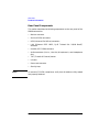
This chapter contains the following topics:
• Product Information
— “Key Features” on page 17
— “Front Panel Components” on page 19
— “Rear Panel Components” on page 22
— “Memory” on page 31
— “Monitors” on page 31
• Getting Started
— Operating System Overview
— Information You Need to Record
— Gathering Required Information
— Powering on the Workstation for the First Time
— Documentation
16
Chapter 1
Overview
Product Information
Product Information
This section describes the key features and the components of the B2000
workstation. The purpose of this section is to familiarize you with your
new workstation.
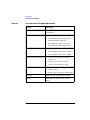
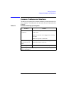
Key Features
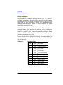
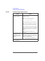
Table 1-1 lists the key features of the HP VISUALIZE B2000 workstation.
Table 1-1
Key Features of the B2000 Workstation
Feature
Description
Processor
400 MHz PA-Risc processor with 1.5 MB
cache
Operating System
HP-UX 10.20 with the 9912 Additional Core
Enhancements (ACE) software bundle
(December 1999)
User Interface
HP Common Desktop Environment (CDE)
graphical user interface
Compatibility
Source and binary code compatible with the
B- and C-Class product families
Main Memory
Four memory slots supporting 128MB,
256MB and 512 MB memory DIMMs.
Minimum memory configuration is 256 MB,
and maximum is 2 GB.
Internal Storage Devices
•
One standard 9 GB 7200 RPM Ultra2
Wide Low-Voltage Differential (LVD)
SCSI hard disk drive; a second 9 GB
7200 RPM Ultra2 Wide LVD SCSI hard
disk drive is optional
•
One standard ATAPI CD drive, 32×
ATAPI
•
One optional 3.5-inch floppy disk drive
Chapter 1
17
Overview
Product Information
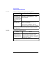
Table 1-1
Key Features of the B2000 Workstation
Feature
Description
Standard Networking
Ethernet IEEE 802.3, RJ45 Twisted Pair
10/100 BaseT
Standard I/O
•
Two Serial (RS-232) ports
•
Two USB (Universal Serial Bus) ports
•
One Parallel (IEEE 1284) port
•
Four Audio ports (Line In, Line Out,
Microphone In, and Headphones Out)
I/O Expansion Capabilities
Monitors Currently Supported
Graphics
Four PCI (Peripheral Connect Interface) slots:
•
Two 64-bit PCI-2X slots at 5V, 33 MHz
•
Two 32-bit PCI-1X slots at 5V, 33MHz
•
21-inch, 1280×1024 (stereo capable)
color, 75 Hz
•
21-inch, 1600×1200 color, 75 Hz
•
19-inch, 1280×1024 color, 75 Hz
• Integrated HP VISUALIZE fxe graphics chip
on system board
•
HP VISUALIZE fxe graphics card (optional)
Keyboard
USB (Universal Serial Bus) HP keyboard
Mouse
USB (Universal Serial Bus) HP 3 button
mouse
18
Chapter 1
Overview
Product Information
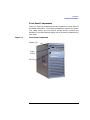
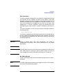
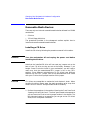
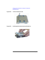
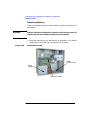
Front Panel Components
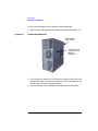
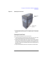
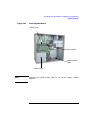
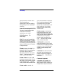
Figure 1-1 shows the components that are located on the front panel of
the B2000 workstation. The following subsections describe the system
LCD, power switch, and the internal storage devices (including the
standard CD drive and optional floppy disk drive) that are located on the
front panel.
Figure 1-1
Front Panel Components
System LCD
Power
Switch
CD Drive
Chapter 1
19
Overview
Product Information
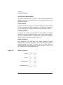
System LCD
The Liquid Crystal Display (LCD) is located on the left side of the front
panel. The LCD has a 2-line display, with up to 16 characters per line.
The LCD displays progress messages and error messages. Error
messages, known as chassis codes, are used in troubleshooting. The
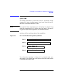
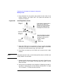
symbols in Figure 1-2 appear in the LCD, representing different system
activities.
Figure 1-2
LCD Symbols
Operating system running
Disk access in progress
Network receive in progress
Network transmit in progress
For more information, see the “LCD Information” section in Chapter 6.
Power Switch
The power switch is also located on the left side of the front panel. Use
the power switch to power your workstation on and off.
When you press the power switch to power off your workstation, the
operating system executes an automatic shutdown -q command. This
prevents any damage to programs and data on your system disk.
Pressing the power switch on again automatically boots up the HP-UX
operating system, if your system has been configured to auto boot. For
information on setting auto boot, see “Setting the Auto Boot and Auto
Search Flags” in Chapter 5.
20
Chapter 1
Overview
Product Information
Internal Storage Devices
The B2000 workstation has one 9 GB 7200 RPM Ultra2 Wide
Low-Voltage Differential (LVD) SCSI hard disk drive as a standard
component. Optionally, the workstation also supports a second 9 GB
7200 RPM Ultra2 Wide LVD SCSI hard disk drive.
In addition, the B2000 workstation has one ATAPI CD drive as a
standard component. Optionally, the workstation also supports one
3.5-inch floppy disk drive.
NOTE
You cannot have two CD drives nor two floppy disk drives, since the
B2000 workstation only supports one each of these devices.
Figure 1-1 on page 19 shows the workstation with one CD drive
installed. See Chapter 2 for detailed descriptions of the CD drive controls
and Chapter 3 for detailed descriptions of the floppy disk drive controls.
Chapter 1
21
Overview
Product Information
Rear Panel Components
This section describes the following components on the rear panel of the
B2000 workstation:
• Monitor connector
• Serial (RS-232) connectors
• USB (Universal Serial Bus) connectors
• LAN (Ethernet IEEE 802.3, RJ45 Twisted Pair 10/100 BaseT)
connector
• Parallel (IEEE 1284) connector
• Audio connectors (Line In, Line Out, Microphone In, and Headphones
Out)
• TOC (Transfer Of Control) button
• I/O slots
• Power cord connector
• Security loop
NOTE
To maintain FCC/EMI compliance, verify that all cables are fully seated
and properly fastened.
22
Chapter 1
Overview
Product Information
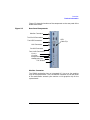
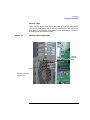
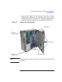
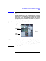
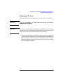
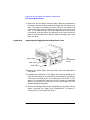
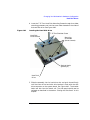
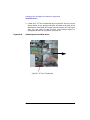
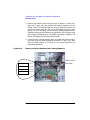
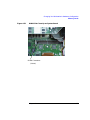
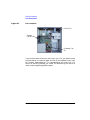
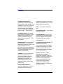
Figure 1-3 shows the locations of the components on the rear panel of the
B2000 workstation.
Figure 1-3
Rear Panel Components
Monitor Connector
Two Serial Connectors
Two USB Connectors
USB
Cable Clip
LAN Connector
Parallel Connector
Four Audio Connectors:
Line In
Line Out
Microphone In
Headphones Out
TOC Button
Monitor Connector
The B2000 workstation has an integrated HP VISUALIZE fxe graphics
chip on the system board. Thus, the monitor connector on the rear panel
of the workstation connects your monitor to this graphics chip on the
system board.
Chapter 1
23
Overview
Product Information
Serial Connectors
You can attach a variety of pointing devices (such as a mouse or
trackball) or peripheral devices (including printers, plotters, modems,
and scanners) to the two Serial Input/Output (SIO) RS-232 ports on the
rear panel of this workstation. Consult the documentation that
accompanies each pointing device or peripheral device for specific
information concerning its use.
The SIO ports are programmable, allowing functions such as bit rate,
character length, parity, and stop bits to be set. You can set these by
using the HP-UX System Administration Manager (SAM) utility, or by
selecting a system special device file with the functions already
programmed. The SIO ports are used as an interface for serial
asynchronous devices to the CPU.
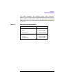
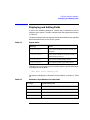
Table 1-2 shows the SIO connector pin listings. The serial connectors are
9-pin D-sub connectors. Signal names are those specified in the EIA
RS-232 standard.
Table 1-2
24
Serial I/O Pins
Pin No.
Signal
Description
1
DCD
Data Carrier Detect
2
RXD
Receive Data
3
TXD
Transmit Data
4
DTR
Data Terminal Ready
5
GND
Ground
6
DSR
Data Set Ready
7
RTS
Request To Send
8
CTS
Clear To Send
9
RI
Ring Indicator
Chapter 1
Overview
Product Information
USB Connectors
The USB connectors located on the rear panel of the workstation provide
and interface for the keyboard ad mouse to the system. These USB
connectors support only the HP keyboard, HP mouse and USB hub. The
keyboard and mouse may be plugged into either USB connector on the
rear of the workstation or plugged into the USB hub. No other USB
configuration is currently supported. Consult the documentation that
accompanies each input device for specific information concerning its
use.
For more information on USB, see the Universal Serial Bus website at
the following URL:
http://www.usb.org
The following subsections briefly describe each of the three USB devices
you can connect to the B2000 workstation’s USB connectors. The mouse
and keyboard were shipped with your workstation, and the USB hub can
be ordered separately.
CAUTION
Usage of devices other than USB specification may result in
unpredictable functionality and inferior performance of the B2000
workstation.
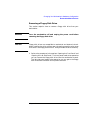
NOTE
The USB cable clip on the rear of the chassis provides strain relief for the
USB cables. Open the cable clip, loop the cables through the clip and
snap it closed to secure the USB cables. See Figure 1-3 on page 23.
HP USB Keyboard
The HP USB keyboard provides the standard keycaps found on most PC
keyboards.
NOTE
The USB keyboard and mouse may be plugged into either USB connector
on the rear of the B2000 workstation.
Chapter 1
25
Overview
Product Information
HP USB Three Button Mouse
For general information on the various cursor shapes associated with
different areas of HP CDE while using a mouse, see the Using Your HP
Workstation manual.
LAN Connector
Your workstation has one built-in, Ethernet IEEE 802.3, RJ45 Twisted
Pair (TP) connector for 802.3 (Ethernet) or 10/100 BaseT networking.
Your workstation will automatically select the correct network setting.
Parallel Connector
The 25-pin HP Parallel I/O interface uses IEEE 1284 I/O interface
protocols to support peripheral devices such as printers and plotters.
consult the documentation that accompanies each parallel peripheral
device for specific information concerning its use.
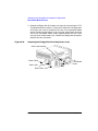
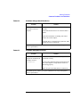
Audio Connectors
Your workstation has audio-input and -output capability through
external input and output connectors on the rear panel and through an
internal speaker. As shown in Figure 1-4 on the next page, the
workstation’s rear panel contains four audio connectors: Line In, Line
Out, Microphone In, and Headphones Out.
Figure 1-4
Audio Connectors
Line In
Line Out
Microphone In
Headphones Out
26
Chapter 1
Overview
Product Information
The audio connectors are standard stereo audio mini-jacks.
Hewlett-Packard recommends using gold-plated plugs available through
audio retailers for best quality recording and playback through the
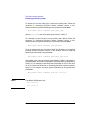
external connectors. The audio electrical specifications are summarized
in Table 1-3.
Table 1-3
Audio Electrical Specifications
Frequency Response
25 Hz to 20 kHz
Input Sensitivity/Impedance:
Line in
Microphone in
2.8Vp-p/10Kohm
40mVp-p/47Kohm
Maximum Output Level/Impedance:
Line out
Headphone out
Chapter 1
2.8Vp-p/920ohm
5.6Vp-p/110ohm
27
Overview
Product Information
TOC Button
You can press the TOC (Transfer Of Control) button on the rear panel to
interrupt the system.
I/O Slots
The four I/O slots located on the rear panel are PCI (Peripheral Connect
Interface) slots, which you can use for add-on I/O interface cards. There
are two PCI-2X slots and two PCI-1X slots, which are defined as follows:
Slot 1: 64-bit PCI-2X at 5V, 33 MHz
Slot 2: 64-bit PCI-2X at 5V, 33 MHz
Slot 3: 32-bit PCI-1X at 5V, 33 MHz
Slot 4: 32-bit PCI-1X at 5V, 33 MHz
For more information, see the “I/O Cards” on page 81 in Chapter 4.
Power Cord Connector
Plug the workstation’s power cord into the power cord connector to
provide AC power to the workstation.
28
Chapter 1
Overview
Product Information
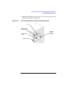
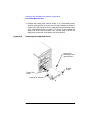
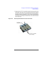
Security Loop
There is also a security loop on the rear panel of the B2000 workstation.
The security loop allows you to lock the workstation’s left side panel,
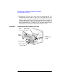
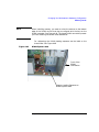
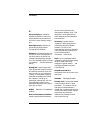
thus securing the internal components of your workstation. Figure 1-5
provides a view of the security loop.
Figure 1-5
Security Loop Components
Security
Loop Pin
Hole
Security Loop Pin
and Spring
Chapter 1
29
Overview
Product Information
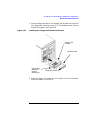
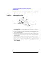
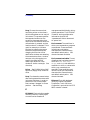
To lock your workstation’s left side panel, follow these steps:
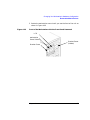
1. Make sure the workstation’s left side panel is closed. See Figure 1-6.
Figure 1-6
Closed Left Side Panel
Workstation’s
Front Panel
Left Side Panel
(using the front
panel as
reference)
2. Push the security loop’s pin into the security loop pin hole, and insert
the padlock’s latch through the holes at the top and bottom of the
security loop. This locks the left side panel.
3. Lock the padlock. Your workstation’s left side panel is now secure.
30
Chapter 1
Overview
Product Information
Memory
The B2000 workstation has four slots for memory DIMMs. You can
install only 128 MB, 256 MB, or 512 MB DIMMs in these slots. The
minimum memory configuration for a B2000 workstation is 256 MB, and
the maximum is 2 GB.
To install memory DIMMs in your workstation, follow the procedure in
the “Installing Additional Memory” on page 132. Please keep in mind
that if memory is installed improperly or if it is bad, your workstation’s
operating system will not boot-up, and a DIMM error message will
appear on your workstation’s LCD. If a DIMM error does occur, please
refer to the “Memory Failures” section in Chapter 6.
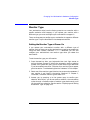
Monitors
Your HP monitor should be set to one of the following resolutions:
• 1280×1024 color (stereo capable), 75Hz, VESA
• 1600×1200 color, 75Hz, VESA
• 1280×1024 color, 75 Hz, VESA
Your workstation must have either an HP-supported monitor running at
75 Hz with a 1280×1024 resolution, or a full multi-mode color monitor.
Monitors with EVC, D-Sub, or 5 BNC connectors (RGB, vertical sync,
horizontal sync) will function.
NOTE
The HP VISUALIZE fxe graphics card will not function with older HP
monitor types that use a sync on green signal. This includes monitors
such as the HP 1097A/B/C/D, A2088A, and A2828A/B that only have 3
BNC connectors.
Note that you can connect the B2000 workstation to earlier HP monitors
with 15-pin miniature D-Sub cables using the A4168A adapter shipped
with your workstation’s accessory kit.
Before using your monitor, you should become familiar with its controls,
connectors, and indicators. For information about using your monitor, see
the documentation that came with the monitor.
Chapter 1
31
Overview
Getting Started
Getting Started
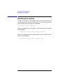
Operating System Overview
Your B2000 workstation runs the HP-UX 10.20 operating system with
the 9912 Additional Core Enhancements (ACE) software bundle
(December 1999).
The B2000 is an Instant Ignition system (that is, a workstation with
preloaded software). It has X-Windows, HP’s graphical user interface,
and HP CDE (Common Desktop Environment) installed and configured.
Please refer to the “System Information” sheet that came with your
workstation for details on configuration. If your Instant Ignition system
does not have the kernel preconfigured with all of the required device
drivers, refer to the Managing Systems and Workgroups manual to
configure your kernel. If you have any questions about Instant Ignition,
refer to the Using Your HP Workstation manual for more information.
NOTE
You can find the documents mentioned in the previous paragraph on
HP’s documentation website at the following URL:
http://www.docs.hp.com/
32
Chapter 1
Overview
Getting Started
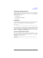
Information You Need to Record
Before you begin using your workstation, take a moment to gather the
following important information and record it in the appropriate
subsection for future use:
• LAN Station ID
• IP (Internet Protocol) address
• Subnet mask
LAN Station ID
Locate the contents label that came with your workstation’s shipping
carton. Find the LAN Station ID listed there and record it here:
LAN Station ID:__________________________________________________
The LAN Station ID can also be found on the back of the workstation
near the LAN connector. If the previous methods for locating your LAN
Station ID do not work, you can get your LAN Station ID by executing
the lanscan command in a terminal window.
IP Address and Subnet Mask Information
Get the IP address and the subnet mask information for your
workstation from either your system administrator or your network
administrator and note them here:
IP Address: ______________________________________________________
Subnet Mask: ____________________________________________________
Chapter 1
33
Overview
Getting Started
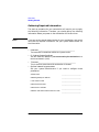
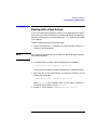
Gathering Required Information
The start-up procedure for your workstation will require you to supply
the following information. Therefore, you should gather the following
information before you power on the workstation for the first time.
NOTE
If you are not the system administrator for your workstation, and you do
not know the required information, ask your system administrator for
the information.
• Hostname _____________________________________________
The hostname is sometimes called the “system name.”
• IP (Internet Protocol) address ________________________________
You will need this address if you are connecting the workstation to a
local area network (LAN).
• Time zone ______________________________________________
This is the time zone where the workstation is located.
• Optional networking parameters
Ask your system administrator if you need to configure these
parameters.
34
Subnet mask
________________________
Network gateway IP address
________________________
Local domain name
________________________
DNS server host name
________________________
DNS server IP address
________________________
Network Information Service domain name
________________________
Chapter 1
Overview
Getting Started
• Optional font server parameters
You need to supply these parameters if you want the workstation to
obtain its fonts from a network server. Ask your system administrator
if you need to configure these parameters.
Font server name
__________________________
Font server IP address
__________________________
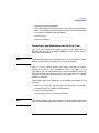
Powering on the Workstation for the First Time
After you have connected the various parts of your workstation by
following the HP VISUALIZE B2000 Installation Card, you are ready to
power on the workstation.
NOTE
Your B2000 workstation may be powered on in the minitower, upright
position, or powered on while laying on the right-side panel.
The HP Instant Ignition process has already installed the HP-UX
operating system on your workstation. When you power on the
workstation, you will be presented with a series of questions. When you
have answered these questions, the HP CDE login screen will appear.
Once the HP CDE login screen appears, you can log in as root—initially
there is no password.
Follow these steps when powering on your B2000 workstation for the
first time:
1. Power on the monitor and any external peripherals (for example,
printers) that are connected to the workstation.
2. Power on the workstation.
The workstation will run a series of self-tests.
NOTE
Your display monitor may appear blanked for a few moments while the
system is booting. Messaging will appear in approximately two minutes.
Chapter 1
35
Overview
Getting Started
3. A series of messages are displayed as various hardware and software
subsystems are activated.
During the initial boot process you will be asked to:
• Select a monitor type
• Select the appropriate keyboard type
4. Enter the required information about your workstation when
prompted for it. This is the information you gathered in the previous
subsection, such as your workstation’s hostname, IP address, and
time zone.
NOTE
You should enter the hostname when requested; otherwise, you will get
an error message when you log in.
If you do not have other required pieces of information, press Enter to use
the default value. You can provide missing information later by logging
into a terminal emulator window as root and executing this command:
/sbin/set_parms
5. Specify the root password when prompted for it. The root password
is the password used for the superuser account. (The superuser, root,
is a special user who has permission to perform all system
administration tasks.)
When you have finished answering all of the questions, the
workstation completes its start-up sequence and displays the HP
CDE login screen.
6. Log into your first HP CDE session as root. For information on
logging into HP CDE, see the Common Desktop Environment User’s
Guide.
NOTE
You must log into the first session as root. This is because the system
contains no other user accounts. Once you have created user accounts,
you should log out as root and log back in as one of the other users.
36
Chapter 1
Overview
Getting Started
7. After you log into your first HP CDE session you can customize the
desktop user interface for your specific language. For detailed
information to configure localized desktop sessions, see the Common
Desktop Environment User’s Guide.
8. Use the HP-UX System Administration Manager (SAM) utility to
set-up user accounts.
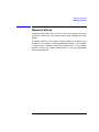
Documentation
Additional documentation for your system is located on the “Instant
Information” CD that is shipped with the keyboard accessory kit. To view
this CD, follow the special mounting instructions that came with the CD.
Chapter 1
37
Overview
Getting Started
38
Chapter 1
2
Using Your CD Drive
This chapter provides an overview of the optional CD drive and media as
well as an explanation of how to use the CD drive.
39
Using Your CD Drive
Here are the topics covered in this chapter:
• Operating the CD Drive
• Mounting and Unmounting a CD
• Verifying the CD Drive Operation
• Configuring the CD Driver
• Audio Control for the CD Drive
• CD Media Description
The instructions in this chapter assume you are using the HP-UX 10.20
operating system and Workstation Additional Core Enhancements for
HP-UX 10.20 (December 1999) with the HP CDE interface.
For information about installing or removing a CD drive, see Chapter 4
of this document.
NOTE
Be sure you have read and understand the information on mounting and
unmounting CDs before you begin using your CD drive.
NOTE
This chapter requires you to be superuser (root). If you cannot log in as
root, contact your system administrator.
In this chapter, the terms “CD” and “CD drive” are used rather than
“CD-ROM” and “CD-ROM drive” because the CD drive used in the B2000
can read the original CD-ROM disks, plus CD-R disks and the newer
CD-RW disks (also called “CD-RAM” because they are rewriteable).
Thus, since not all CDs are ROMs any longer, that portion of the term
has been dropped.
Incidentally, the CD drives also are multisession-capable.
40
Chapter 2
Using Your CD Drive
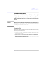
CD Media Description
CD Media Description
CDs, which can be CD-ROMs, CD-Rs, or CD-RWs, are 120mm (4.7
inches) in diameter, and use one data surface with a capacity of 600
megabytes. The data surface contains pits and flat spots arranged in a
continuous spiral track, which is read at a constant speed. You may
access files and data stored on a CD, but you may not write files or data
to a CD.
CAUTION
Handle CDs by the edges only. Always be sure a CD is either in the CD
drive or its protective case when not in use. This will reduce the chance
of exposing the disk surface to dust. Over time, dust reduces the
reliability of the read head in the CD drive.
Caring for CDs
Observe the following guidelines to help prevent data loss and prolong
the life of you CD and CD drive:
• Use CDs in a clean environment to prevent dust particles from
scratching disc surfaces.
• Store CDs in a cool, dry place to prevent moisture and heat damage.
• Do not try to clean the surface of a CD with cleaning solvents, as some
cleaning solvents may damage the disk.
Chapter 2
41
Using Your CD Drive
Operating the CD Drive
Operating the CD Drive
This section provides a description of the CD drive and it describes how
to perform tasks with your CD drive.
CD Drive
The CD drive is a mass storage device that can read removable CD-ROM,
CD-R, and CD-WR media. The drive supports the ISO 9660 and High
Sierra format standards. You can access information from the drive like
any other disk drive, except you cannot write to the drive. The drive
contains a semiconductor laser for reading data optically, and includes
an embedded controller with an ATAPI interface.
42
Chapter 2
Using Your CD Drive
Operating the CD Drive
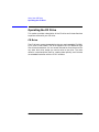
Controls and Features
Figure 2-1 and Table 2-1 describe the operating controls and features of
the CD drive.
NOTE
The exact positioning of CD Drive controls/features may vary depending
on the model of the device.
Figure 2-1
CD Drive Controls and Features
Disk
Tray
Busy Indicator
Table 2-1
Emergency Eject
Eject Button
CD Drive Operating Controls and Features
Control/Feature
Purpose
Headphone Jack
Accommodates mini-headphones with a 3.5 mm
diameter miniature stereo plug.
Volume Control
Adjusts the audio output volume to the headphone.
Busy Indicator
The Busy Indicator blinks during a data transfer.
Eject Button
The Eject Button when pressed opens the Disk Tray
for removal or insertion of a disk. When the drive is in
use, you must press the eject button for more than one
second to open the Disk Tray.
Emergency Eject
You can open the Disk Tray when the workstation
does not have power by inserting the end of a paper
clip into this opening.
Disk Tray
The Disk Tray holds the CD. This style of CD drive
does not use a disk caddy.
Chapter 2
43
Using Your CD Drive
Operating the CD Drive
To listen to an audio CD, use the headphone jack on the rear panel, and
control the sound volume via software called “xmcd” (for details, see
“Audio Control for the CD Drive” on page 56).
44
Chapter 2
Using Your CD Drive
Operating the CD Drive
Loading and Unloading a CD
This section explains how to load or unload a CD.
NOTE
To use the file system on a CD, you must be superuser (root) and mount
the disk as discussed in the section “Mounting a CD Using SAM.” Once
the CD has been mounted, you must unmount it before removing the CD.
Unmounting a CD is discussed in the section “Unmounting a CD Using
SAM.”
Loading a CD
This CD drive has an automatic loading/ejecting feature. To load a CD in
the CD drive, follow these steps:
1. Press and release the eject button on the CD drive. The disk tray
opens as shown in Figure 2-2.
Figure 2-2
Open CD Tray
Chapter 2
45
Using Your CD Drive
Operating the CD Drive
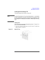
2. Hold the disk by the edges with the label side up and place it in the
disk tray as shown in Figure 2-3.
Figure 2-3
Placing the CD in the Disk Tray
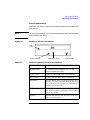
3. Press the eject button to close the tray as shown in Figure 2-4.
Figure 2-4
Closed Disk Tray
46
Chapter 2
Using Your CD Drive
Operating the CD Drive
Unloading a CD
To unload a disk from the Disk Tray, follow these steps:
1. Press and release the eject button on the CD drive to open the disk
tray.
2. Grasp the disk by the edges and lift it out of the disk tray.
3. Press the Eject Button to close the disk tray.
Locating Help
If you have trouble with any of the procedures for using your CD drive,
see the chapter “Solving Problems” in this document.
Chapter 2
47
Using Your CD Drive
Mounting and Unmounting a CD
Mounting and Unmounting a CD
This section of the chapter explains how to mount and unmount a CD
drive using the System Administration Manager (SAM).
The procedures in this section require you to log in as root. If you cannot
log in as root, contact you system administrator.
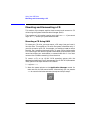
Mounting a CD Using SAM
To access your CD drive, you must mount a CD every time you insert it
into the drive. This applies to CDs with file system information only. If
you wish to load a music CD, for example, you would not need to mount
the disk. See “Installing the xmcd Utility” on page 56 for playing audio
CDs. Mounting a disk with file system information gives the disk a path
name that allows your workstation to communicate with it. You must
unmount the CD before removing it from the drive.
To mount a CD on an HP-UX 10.20 operating system with the
Workstation Additional Core Enhancements for HP-UX 10.20 (December
1999), perform the steps covered in this section.
1. Log in as root.
2. Move the mouse pointer to the Application Manager control for
tools and click the left mouse button. Alternatively you can execute
sam at a terminal window command prompt and skip to step 5.
48
Chapter 2
Using Your CD Drive
Mounting and Unmounting a CD
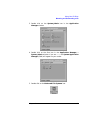
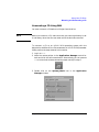
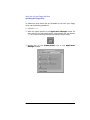
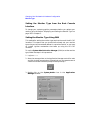
3. Double click on the System_Admin icon in the Application
Manager window.
4. Double click on the Sam icon in the Application Manager -System_Admin window. If you are root, the System Application
Manager (SAM) will appear on your screen.
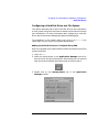
5. Double click on the Disks and File Systems icon.
Chapter 2
49
Using Your CD Drive
Mounting and Unmounting a CD
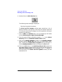
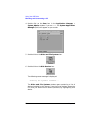
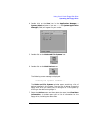
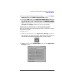
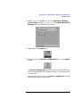
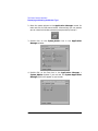
6. Double click on the Disk Devices icon.
The following screen message is displayed:
Scanning the system’s hardware...
The Disk and File Systems window opens containing a list of
devices installed in this system. From the list of devices, choose the
CD drive you would like to configure as a file system by clicking on
the device to highlight it.
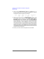
7. Click on Add in the Actions menu. For this example you will select
the item Not Using the Logical Volume Manager.
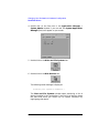
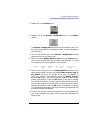
8. Enter the mount directory name (for example, /disk1) in the Mount
Directory field of the Add Disk without LVM window.
9. Click on the Modify Defaults... button. In the Modify Defaults
window, select the Read Only item from the Access button menu.
Next, unselect the Create New File System item by clicking on it.
Exit the Modify Defaults window by clicking on the OK button.
10. Click on the OK button in the Add Disk without LVM window. You
will need to wait for a short time for the CD to be mounted. When the
Add Disk without LVM window disappears and CDFS appears in
the Use column of the Disks and File Systems window, you have
mounted the CD.
50
Chapter 2
Using Your CD Drive
Mounting and Unmounting a CD
Unmounting a CD Using SAM
You must unmount a CD before it will eject from the drive.
NOTE
Before you unmount a CD, make sure that your working directory is set
to a directory other than the one under which the disk was mounted.
To unmount a CD on an HP-UX 10.20 operating system with the
Workstation Additional Core Enhancements for HP-UX 10.20 (December
1999), perform the steps covered in this section.
1. Log in as root.
2. Move the mouse pointer to the Application Manager control for
tools and click the left mouse button. Alternatively you can execute
sam at a terminal window command prompt and skip to step 5.
3. Double click on the System_Admin icon in the Application
Manager window.
Chapter 2
51
Using Your CD Drive
Mounting and Unmounting a CD
4. Double click on the Sam icon in the Application Manager -System_Admin window. If you are root, the System Application
Manager (SAM) will appear on your screen.
5. Double click on the Disks and File Systems icon.
6. Double click on the Disk Devices icon.
The following screen message is displayed:
Scanning the system’s hardware...
The Disks and File Systems window opens containing a list of
devices installed in this system. From the list of devices, choose the
CD drive you would like to remove (unmount) by highlighting that
device.
52
Chapter 2
Using Your CD Drive
Mounting and Unmounting a CD
7. Click on Remove in the Actions menu. In the window that next
appears, click on the Yes button. This will unmount the CD. You will
need to wait for a short time before the CD is unmounted. The CD is
successfully unmounted when you see Unused in the Use column of
the Add Disk without LVM window.
Chapter 2
53
Using Your CD Drive
Verifying the CD Drive Operation
Verifying the CD Drive Operation
To verify that your workstation can communicate with the CD drive,
follow the steps covered in this section. Note that to perform the steps
required in this section, you must be superuser (root). If you cannot log
in as root contact your system administrator.
1. Log in as root.
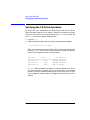
2. Type the following command at the shell prompt and press Enter:
/usr/sbin/ioscan -d sdisk
After a few seconds the ioscan utility lists all of the I/O devices that
use the “sdisk” driver. Your CD drive should be among the devices
listed. The list appears similar to the following:
H/W Path
Class
Description
===============================================
10/0/15/1.5.0
disk
SEAGATE ST39102LC
10/0/15/1.6.0
disk
SEAGATE ST39102LC
10/0/14/0.0.0
disk
TEAC CD-532E-B
If ioscan does not detect any usable I/O system devices, such as the
CD drive, nothing is output and you are returned to the system
prompt. Since this indicates possibly that the driver for the CD drive
is not configured, read the section “Configuring the CD Driver” in this
chapter.
54
Chapter 2
Using Your CD Drive
Configuring the CD Driver
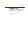
Configuring the CD Driver
If you reload software or rebuild the Instant Ignition system on your
workstation, you may need to reconfigure the HP-UX kernel to add the
CD driver. Use the SAM utility to add the CD driver and build a new
HP-UX kernel.
For more information about how to reconfigure the kernel using SAM,
see the following manuals:
• Managing Systems and Workgroups
• Using HP-UX
Chapter 2
55
Using Your CD Drive
Audio Control for the CD Drive
Audio Control for the CD Drive
In order to control the playing of audio CDs on your CD drive, you will
need a third party “CD player” application. One such application that
supports HP workstations is xmcd. This is a third-party “CD player”
utility that runs on an X window system using the Motif graphical user
interface. The xmcd utility is not supported by Hewlett-Packard. Since
the xmcd utility is not a part of HP-UX, you will need to download it off
the web using your web browser and this URL:
http://metalab.unc.edu/tkan/xmcd
Installing the xmcd Utility
Here is the procedure for downloading the xmcd utility to your system:
1. Log in as root.
2. Type the previously given URL into the entry box on your web
browser and press Enter.
3. Select the menu item labeled Downloads found on the xmcd
homepage.
4. Scroll down to the section “Select your platform:” on the Downloads
web page and select the item labeled “HP-UX 9.x and later (HP
PA-RISC).”
5. Wait for a few seconds for the Save As... pop-up window to appear. In
this window, click in the Selection entry box and type the following
path and file name:
/tmp/xmcdbin.tar.gz
Next, click the OK button. This completes the download of xmcd to
your system.
6. Follow the instructions in the section “Instructions to unpack xmcd
binary” found on this Binary Downloads web page. This will
complete the installation of the xmcd utility.
56
Chapter 2
Using Your CD Drive
Audio Control for the CD Drive
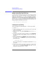
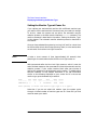
Using the xmcd Utility
The instructions in the section assume that you are using the HP-UX
10.20 operating system and the Workstation Additional Core
Enhancements (ACE) for HP-UX 10.20 (December 1999) with the HP
CDE interface. The xmcd utility must also be installed on your system.
See the section “Installing the xmcd Utility.”
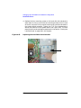
To load and play an audio CD, follow the steps in this procedure.
1. Load the audio CD. See the section “Loading a CD” in this chapter.
2. Insert the headphone plug into the headphone jack located on the
back of your system unit.
Line Input Jack
Line Output Jack
Microphone Jack
Headphone Jack
3. Click on the Audio icon located on your HP CDE control panel.
Audio Icon
Chapter 2
57
Using Your CD Drive
Audio Control for the CD Drive
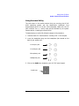
4. Click on the Monitoring checkbox in the Audio window to select it.
Then select the Output menu and click on the Headphones item in
the menu list. In the File menu select the item Close, this will close
the Audio window and save your settings. Note that the Output
Volume slider in the Audio window does not control the CD drive’s
volume level. To control the CD drive’s volume, you need to use the
volume slider on the xmcd user interface. See the window in step 5.
5. Start the utility by typing xmcd at the prompt and pressing Enter.
Play/Pause
Button
Eject
Button
Help Button
Stop
Button
Volume Slider
Keypad
Now that you have your audio CD player started, put on your
headphones and press the Play button to listen to the audio CD. Note
that pressing the Help button will give you information on how to use
the rest of the CD player’s buttons.
58
Chapter 2
3
Using Your 3.5-Inch Floppy Disk
Drive
This chapter describes how to perform tasks that allow you to archive to
or transfer data from the 3.5-inch floppy disk drive.
59
Using Your 3.5-Inch Floppy Disk Drive
The instructions in this chapter assume you are using the HP-UX 10.20
operating system and the Workstation Additional Core Enhancements
for HP-UX 10.20 (December 1999) with the HP CDE interface.
NOTE
When examples of user input are given in this chapter, enter them at the
command-line prompt in an HP CDE terminal window.
Some procedures in this chapter require you to log in as superuser
(root). If you cannot log in as root, contact your system administrator.
Here are the topics covered in this chapter:
• Operating the Floppy Drive
• Verifying the Floppy Drive Configuration
• Additional Floppy Drive Information.
For information on installing and removing a floppy disk drive, see
Chapter 4 of this document.
60
Chapter 3
Using Your 3.5-Inch Floppy Disk Drive
Operating the Floppy Drive
Operating the Floppy Drive
This section describes how to perform tasks with your 3.5-inch floppy
disk drive.
Floppy Disk Drive
The floppy disk drive is a random access read/write mass storage device
that uses removable floppy diskettes. The drive supports the 1.44 Mbyte
High Density standard. You can access information from the drive like
any other disk drive, that is you can write information to it and read
information from it.
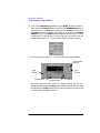
Controls and Features
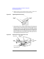
Figure 3-1 and Table 3-1 describe the operating controls and features of
the floppy disk drive.
Figure 3-1
Floppy Disk Drive Controls and Features
Busy Indicator
Table 3-1
Eject Button
Floppy Disk Drive Operating Controls and Features
Control/Feature
Purpose
Busy Indicator
The Busy Indicator illuminates during a data
access operation and blinks during a data
transfer.
Eject Button
The Eject Button, when pressed, ejects the
floppy diskette from the floppy disk drive.
Chapter 3
61
Using Your 3.5-Inch Floppy Disk Drive
Operating the Floppy Drive
Using the Floppy Diskette
This section describes basic information needed to use your floppy
diskettes.
Setting the Write-Protect Tab on a Diskette
You can only store or change information on a diskette when the
write-protect tab is in the write position. So, before trying to write to the
diskette, make sure that the write-protect tab is in the write position, as
shown in Figure 3-2.
Figure 3-2
Setting the Write-Protect Tab on a Floppy Diskette
Write-Protect Tab
Slide tab up for
write-protect
Slide tab down to
write
To protect files on a diskette from being overwritten, set the
write-protect tab to the write-protect position.
NOTE
The write-protect tab should always be in the write position for
formatting a new diskette and transferring data to a diskette.
62
Chapter 3
Using Your 3.5-Inch Floppy Disk Drive
Operating the Floppy Drive
Inserting and Removing a Diskette
Follow these steps to insert and remove a diskette from the floppy disk
drive.
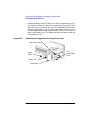
1. Insert the diskette into the drive, as shown in Figure 3-3.
Figure 3-3
Inserting and Removing a Floppy Diskette
2. Push the diskette into the floppy drive until it clicks into place.
3. Remove the diskette by pressing the eject button (see Figure 3-1) and
taking it out of the drive.
Using Device Files
Device files are special files that tell your system which pathway through
the system hardware to use when communicating with a specific device.
Device files also describe the type of device. You will need to know the
special device file associated with your floppy disk drive so that you can
write data to it or read data from it.
NOTE
The device file names depend on the naming conventions of your
particular system.
Chapter 3
63
Using Your 3.5-Inch Floppy Disk Drive
Operating the Floppy Drive
To determine what device files are available for use with your floppy
drive, use the following procedure:
1. Log in as root.
2. Move the mouse pointer to the Application Manager control for
tools and click the left mouse button. Alternatively you can execute
sam at a terminal window command prompt and skip to step 5.
3. Double click on the System_Admin icon in the Application
Manager window.
64
Chapter 3
Using Your 3.5-Inch Floppy Disk Drive
Operating the Floppy Drive
4. Double click on the Sam icon in the Application Manager -System_Admin window. If you are root, the System Application
Manager (SAM) will appear on your screen.
5. Double click on the Disks and File Systems icon.
6. Double click on the Disk Devices icon.
The following screen message is displayed:
Scanning the system’s hardware...
The Disks and File Systems window opens containing a list of
devices installed in this system. From the list of devices, choose the
floppy disk drive you would like to configure as a file system by
clicking on the device to highlight it.
7. Select the Actions menu and then select the menu item View More
Information. A window opens with a list of information for the
floppy drive, including the device files.
Chapter 3
65
Using Your 3.5-Inch Floppy Disk Drive
Operating the Floppy Drive
Formatting a New Diskette
If you have floppy diskettes that have been previously formatted using
the mediainit utility, you can skip this section. Otherwise, you must
always format a new floppy diskette with the mediainit utility before
using the diskette. To format a new floppy diskette, follow these steps:
1. Log in as root.
2. Make sure that the write-protect tab on the floppy diskette is in the
write position, as shown in Figure 3-2.
3. Insert the diskette into the floppy disk drive.
4. Type the following at the prompt and press Enter:
mediainit -f 16 devicefile
where 16 is the High Density (HD) format option and devicefile is
the device file as listed by SAM. See the section “Using Device Files”
in this chapter. For a listing of format options, see the floppy manual
page. To view this manual page, type the following at the prompt and
press Enter:
man floppy
66
Chapter 3
Using Your 3.5-Inch Floppy Disk Drive
Operating the Floppy Drive
Transferring Data To and From a Floppy Diskette
This section describes how to transfer data (reading and writing) to and
from your floppy diskette using the HP-UX tar command with your
floppy drive’s device file.
You need to set the write-protect tab to the write position to transfer data
to the diskette. The write-protect tab can be in either position when
restoring data from a diskette or listing the files on a diskette.
Saving Files to a Floppy Diskette
Use the following instructions to save files to a floppy diskette:
1. Check the write-protect tab on the floppy diskette to ensure that it is
in the write position.
2. Load the formatted floppy diskette into the disk drive.
3. Type the following command in a terminal window at the prompt and
press Enter:
tar -cvf devicefile pathname
where devicefile is the device file as listed by SAM (see the section
“Using Device Files” in this chapter), and pathname is the path name
of the file or directory containing files that you want to write to the
diskette.
Chapter 3
67
Using Your 3.5-Inch Floppy Disk Drive
Operating the Floppy Drive
Restoring Files from a Floppy Diskette to Your System
Use the following instructions to restore files from a floppy diskette to
your system:
1. Load the floppy diskette into the disk drive.
2. Type the following command in a terminal window at the prompt and
press Enter:
cd directory_path
This command changes you to the directory in which you want the
files to reside.
3. Enter the following command at the prompt and press Enter:
tar -xvf devicefile pathname
where devicefile is the device file as listed in SAM (see the section
“Using Device Files” in this chapter) and pathname is the path name
of the file or directory containing files that you want to restore from
the diskette. If you do not specify pathname, everything on the floppy
diskette is restored.
Listing the Files on a Floppy Diskette
Use the following instructions to list the files on a floppy diskette:
1. Load the floppy diskette into the disk drive.
2. Enter the following command in a terminal window at the prompt
and press Enter:
tar -tvf devicefile
where devicefile is the device file as listed by SAM. See the
section “Using Device Files” in this chapter. Note that this command
will list all files on the floppy diskette.
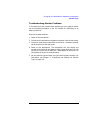
Troubleshooting
If you have trouble with any of the procedures for using your floppy disk
drive, see Chapter 6 of this document, “Solving Problems.”
68
Chapter 3
Using Your 3.5-Inch Floppy Disk Drive
Verifying the Floppy Drive Configuration
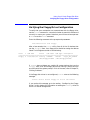
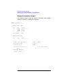
Verifying the Floppy Drive Configuration
To verify that your workstation can communicate with the floppy drive,
use the ioscan command in a terminal window to see which devices are
currently in use on your system. Note that you will have to be superuser
or root to use the ioscan command.
Enter the following command at the prompt and press Enter:
/usr/sbin/ioscan -fnC floppy
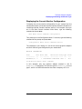
After a few seconds, the ioscan utility lists all of the I/O devices that
use the “floppy” class. Your floppy drive should be among the devices
listed. The list appears similar to the following:
Class
I H/W Path
Driver
S/W State H/W Type Description
========================================================================
floppy 0 10/0/14/1/4.1 sioflop CLAIMED
DEVICE
HP_PC_FDC_FLOPPY
/dev/floppy/c0t1d0 /dev/rfloppy/c0t1d0
If ioscan does not detect any usable I/O system devices that use the
“floppy” class, such as the floppy disk drive, nothing is output and you
are returned to the system prompt. If this is the case, refer to Chapter 6,
“Solving Problems.”
If the floppy disk driver is not configured, ioscan returns the following
message:
ioscan: Device driver floppy is not in the kernel
If you receive this message, go to the section, “Configuring the Floppy
Driver” in this chapter for information on adding the sioflop driver to
the HP-UX kernel configuration.
Chapter 3
69
Using Your 3.5-Inch Floppy Disk Drive
Additional Floppy Drive Information
Additional Floppy Drive Information
This section provides information about configuration of the floppy disk
driver and information about useful HP-UX commands for copying and
listing floppy disk files.
Configuring the Floppy Driver
If you reload software or rebuild the Instant Ignition system on your
computer, you may need to reconfigure the HP-UX kernel to add the
floppy disk driver. Use the SAM utility to add the sioflop disk driver
and build a new HP-UX kernel.
For more information about how to reconfigure the kernel using SAM,
see the following manuals:
• Managing Systems and Workgroups
• Using HP-UX
For More Information
For more information on using tar and a complete list of the command
arguments, refer to the tar man page by typing the following command
in a terminal window at the prompt and pressing Enter:
man tar
You can mount the floppy drive as a file system using the SAM utility. Be
sure to unmount the drive before removing it as a file system. For more
information about how to mount and unmount the floppy drive, see the
manual Using HP-UX.
For more information on copying data to or from your system to other
media, including your floppy diskette, refer to the cpio man page by
typing the following command in a terminal window at the prompt and
pressing Enter:
man cpio
70
Chapter 3
Using Your 3.5-Inch Floppy Disk Drive
Additional Floppy Drive Information
For more information on copying to or from DOS files, refer to the doscp
man page by typing the following command in a terminal window at the
prompt and pressing Enter:
man doscp
For more information on listing DOS directories, refer to the dosls man
page by typing the following command in a terminal window at the
prompt and pressing Enter:
man dosls
For more information on using your floppy disk drive and floppy
diskettes, refer to the floppy man page by typing the following
command in a terminal window at the prompt and pressing Enter:
man floppy
For more information on using the mediainit command, refer to the
mediainit man page by typing the following command in a terminal
window at the prompt and pressing Enter:
man mediainit
Chapter 3
71
Using Your 3.5-Inch Floppy Disk Drive
Additional Floppy Drive Information
72
Chapter 3
4
Changing Your Workstation’s
Hardware Configuration
This chapter contains the procedures to change the hardware
configuration for your HP VISUALIZE B2000 workstation.
73
Changing Your Workstation’s Hardware Configuration
This chapter contains the following topics:
• Front Panel
• Left Side Panel
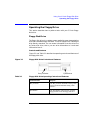
• Power Supply
• I/O Cards
• Fans
• CD Drive and Floppy Drive
• Hard Disk Drives
• Memory Cards
• Monitor Type
The instructions in this chapter assume you are using the HP-UX 10.20
operating system with the Additional Core Enhancements software
bundle (December 1999) with the HP CDE interface. Information for the
HP CDE interface can be found in the HP CDE Getting Started Guide.
CAUTION
Always wear a properly grounded wrist strap when reconfiguring your
workstation with internal devices. For details on electrostatic discharge,
read the section “Electrostatic Discharge (ESD) Precautions” in the
Preface of this manual.
WARNING
Always unplug the workstation’s power cord from the electrical
outlet or power source before opening the workstation.
74
Chapter 4
Changing Your Workstation’s Hardware Configuration
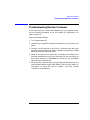
Use the following tools to remove or replace hardware parts when
changing your configuration:
• Light-duty flat blade screwdriver with 150mm (6 inch) long shaft
• T-15 Torx drivers. Note that the screws these drivers are used on have
a recessed slot for use by flat-bladed screwdrivers.
• Needle-nose pliers
NOTE
Many of the HP-UX commands in this chapter will require that you
become superuser (root). If you cannot log in as root, contact your
system administrator.
Chapter 4
75
Changing Your Workstation’s Hardware Configuration
Front Panel
Front Panel
This section explains how to open and close the workstation’s front panel.
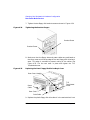
Opening the Front Panel
Perform the following steps to open the workstation.
1. Power off the workstation, and unplug the workstation’s power cord
from the electrical outlet. Note that when you press the workstation’s
power switch, the workstation automatically performs a shutdown
-q.
2. Attach the static-grounding wrist strap by following the instructions
on the package. Attach the sticky end of the wrist strap to bare metal
on the back panel of the workstation.
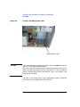
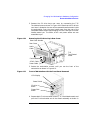
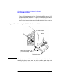
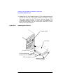
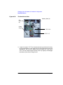
3. Unlatch the front panel (also known as the front bezel) by pressing in
on the two latch buttons located on the right side of the front panel.
See Figure 4-1. If the front panel does not open, you may have to
locate the front panel key and unlock it.
76
Chapter 4
Changing Your Workstation’s Hardware Configuration
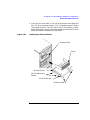
Front Panel
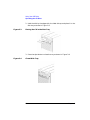
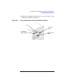
Figure 4-1
Opening the Front Panel
Bezel Latch
Button
Bezel Latch
Button
4. Swing the panel outward on its left snap hinges until the panel comes
free and place the front panel in a location where it cannot get
broken.
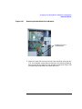
Closing the Front Panel
Perform the following steps to close the workstation.
1. Locate the hinges on the left side of the front panel, and insert them
into the holes located along the left edge of the workstation.
2. Rotate the front panel inward until you hear the two latch buttons
snap in place. The front panel is now closed. If there is a need to lock
the front panel, use the keys that came with your workstation to lock
the panel. These keys are located inside the front bezel below the
floppy disk drive.
3. Plug in the workstation’s power cord, and power on the workstation.
Chapter 4
77
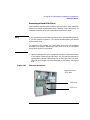
Changing Your Workstation’s Hardware Configuration
Left Side Panel
Left Side Panel
This section explains how to open and close the left side panel of the
workstation. This side panel will have to be opened whenever you need
access to the internal components of the workstation.
Opening the Left Side Panel
Perform these steps to open the left side panel.
WARNING
Always unplug the workstation’s power cord from the electrical
outlet or power source before opening the workstation.
1. Power off the workstation, and unplug the workstation’s power cord
from the electrical outlet.
2. Attach the static-grounding wrist strap by following the instructions
on the package. Attach the sticky end of the wrist strap to bare metal
on the back panel of the workstation.
3. Turn the workstation around so its back is facing you. On the right
edge of the workstation, there are two T-15 Torx thumbscrews as
shown in Figure 4-2. Remove the two T-15 Torx thumbscrews.
78
Chapter 4
Changing Your Workstation’s Hardware Configuration
Left Side Panel
4. Grasp the back edge of the left side panel and rotate it outward
approximately 30 degrees to the workstation. Next, pull the panel
toward you as shown in Figure 4-2. This releases the panel’s top and
bottom left side hook hinges from their hinge slots. See Figure 4-2.
Figure 4-2
Opening the Left Side Panel
Hinge Hook
T-15 Torx
Thumbscrew
EMI Gasket
Hinge Slot
T-15 Torx
Thumbscrew
NOTE
Left Side Panel
The EMI gasket, as shown in Figure 4-2, must not be removed from the
side panel.
Chapter 4
79
Changing Your Workstation’s Hardware Configuration
Left Side Panel
Closing the Left Side Panel
Perform these steps to close the left side panel.
1. Hold the left side panel so that the top and bottom hinge hooks can be
inserted into their hinge slots. See Figure 4-2. Note that the hinge
slots are located on the far right edge of the workstation (using the
back of the workstation as the reference).
2. Swing the back edge of the panel toward the workstation’s back edge
and press the outside edges of the side panel tightly against the
workstation. This will ensure a tight seal of the EMI gaskets.
3. Secure the side panel in place and tighten the two T-15 Torx
thumbscrews you previously removed.
80
Chapter 4
Changing Your Workstation’s Hardware Configuration
I/O Cards
I/O Cards
Your B2000 workstation’s system board has four Peripheral Connect
Interface (PCI) slots for option boards. Slots 1 and 2 are full-size PCI
slots. Slots 3 and 4 are half-size PCI slots.
NOTE
The graphics boards supported by your workstation are designed to be
electrically compatible with PCI option slots. See Table 1-1 on page 17
for graphics option boards supported in the B2000 workstation.
See Figure 4-3 for a brief description of slot capabilities.
Figure 4-3
PCI Card Slot Numbering and Capabilities
Slot 1
64 bits, 33MHz, 5V
Slot 2
64 bits, 33MHz, 5V
Slot 3
32 bits, 33MHz, 5V
Slot 4
32 bits, 33MHz, 5V
The information described in Figure 4-3 is located inside your
workstation on the chassis floor. See Figure 4-4 for the physical location
of the B2000 workstation label.
Chapter 4
81
Changing Your Workstation’s Hardware Configuration
I/O Cards
Figure 4-4
Location of B2000 System Label
B2000 System Label
CAUTION
If you are installing an additional graphics card, you must insert the fx
card in Slot 1 for optimal performance.
After you connect the monitor to the additional graphics card, you will
need to change the graphics path for that monitor. To do this read the
section “Displaying and Setting the Monitor Type” in the chapter “The
Boot Console Interface.”
The label on the chassis floor of your workstation contains important
information for I/O configuration. See Figure 4-5.
82
Chapter 4
Changing Your Workstation’s Hardware Configuration
I/O Cards
Figure 4-5
B2000 System Label
Note that the four I/O slots as seen from the back of the workstation are
labeled from top to bottom starting with one. See Figure 4-6.
Figure 4-6
I/O Slot Numbering
I/O Slot 1
I/O Slot 4
Removing I/O Cards
You will need a T-15 Torx driver or flathead screwdriver to remove the
I/O slot bulkhead screws.
Here are the steps required for remove an I/O card from the workstation.
Chapter 4
83
Changing Your Workstation’s Hardware Configuration
I/O Cards
1. Power off the workstation, and unplug the workstation’s power cord
from the electrical outlet. Note that when you press the workstation’s
power switch, the workstation automatically performs a shutdown
-q.
2. Open the side panel of the workstation as explained in the section
“Opening the Left Side Panel” in this chapter.
3. Pull evenly in the direction of the arrow on both PULL tabs of the I/O
card retainer to remove it. See Figure 4-7.
Figure 4-7
Removing the I/O Card Retainer
I/O Card
I/O Card Retainer
Air Divider
4. Locate the I/O card you want to remove and using a T-15 Torx driver
remove the I/O card’s bulkhead screw as shown in Figure 4-8.
84
Chapter 4
Changing Your Workstation’s Hardware Configuration
I/O Cards
Figure 4-8
Removing the I/O Card
I/O Card
Bulkhead
Screw
I/O Card
Bulkhead
I/O Card Being Removed
5. Pull evenly on the outside edges of the I/O card to remove it. See
Figure 4-8.
Installing I/O Cards
To install an I/O card into your workstation, follow these steps.
NOTE
The built-in VISUALIZE fxe graphics is the primary graphics slot (slot 0).
Use the secondary graphics slot (PCI slot 1) for the highest performance
graphics card and PCI slot 2 for the second graphics card and then any of
the remaining 32 bit slots for the third PCI graphics card.
1. Open the left side panel of the workstation as explained in the section
“Opening the Left Side Panel” in this chapter.
2. Locate the appropriate slot for the I/O card that is to be installed. See
Figure 4-3.
3. Unscrew the T-15 Torx screw and remove the bulkhead blank of the
slot you have chosen. If no blank is present, you may skip to step four.
4. Pull evenly in the direction of the arrow on both PULL tabs of the I/O
card retainer to remove it. See Figure 4-7.
5. Insert the I/O card into the slot you have chosen with the bulkhead
Chapter 4
85
Changing Your Workstation’s Hardware Configuration
I/O Cards
appropriately positioned. See Figure 4-8. If the card is full length, the
non-bulkhead end of the card should be placed in the I/O card guide.
Press firmly and evenly on the I/O card until it is in the connector.
Secure the I/O card to the bulkhead with the T-15 Torx screw.
6. Replace the I/O card retainer by placing the bottom retainer hook in
the slot on the air divider and the clips on the PULL tabs into their
slots on the chassis wall. See Figure 4-7.
7. Close the left side panel of the workstation by following the procedure
in the section “Closing the Left Side Panel” in this chapter.
NOTE
If you connect a monitor to a graphics card, you will need to change the
console path as described in “Displaying and Setting Paths” on page 161.
86
Chapter 4
Changing Your Workstation’s Hardware Configuration
Fans
Fans
The B2000 has three internal fans; processor turbo cooler fan, memory
fan and the I/O fan. The power supply fan is integrated with the power
supply circuitry and is not a stand alone component. Note the turbo
cooler fan is mounted to the processor substrate and is not considered a
user replaceable part. However, if the system indicates a processor fan
failure, the complete system board is replaced.
Figure 4-9
Fan Cooling Areas for the Workstation
I/O Fan
(2)
System Fan
(4)
Processor
Fan (5)
Power
Supply Fan
CAUTION
If one of the fans in the fan areas shown in Figure 4-9 is not working as
indicated by an LCD error message, you need to call your local
Hewlett-Packard support representative. Continuing to operate your
workstation with a bad fan will cause damage to the workstation. To
determine the fan that needs to be replaced, see “LCD Fan Failures and
Warnings” on page 193.
Chapter 4
87
Changing Your Workstation’s Hardware Configuration
Removable Media Devices
Removable Media Devices
There are only two internal removable media devices allowed in a B2000
workstation:
• CD drive
• 3.5-inch floppy disk drive.
The procedures provided in the subsequent sections explain how to
install and remove removable media devices.
Installing a CD Drive
Install the CD drive by following the procedure covered in this section.
WARNING
Turn the workstation off and unplug the power cord before
installing the CD drive.
Note that the installed CD drive will not need any jumpers set on the
back of your CD drive, as they are set at the factory. However, if you
bought a new CD drive to install in your workstation, you will have to
make sure that the master/slave/CSEL jumper is set in the CSEL
position. Since different manufacturers of CD drives have different
locations for the CSEL jumper, look at the documentation that comes
with your CD drive for the proper location of this jumper.
CAUTION
CD drives are susceptible to mechanical and electronic shock. When
handling the drive, always wear the static-grounding wrist strap that
came in the CD drive kit. Always handle the drive carefully.
1. Perform the procedures in the sections “Opening the Front Panel” and
“Opening the Left Side Panel.” The front panel needs to be opened so
you can insert the CD drive into its proper location in the chassis. The
left side panel needs to be opened so you can get to the CD drive’s
audio, ATAPI and power connectors.
88
Chapter 4
Changing Your Workstation’s Hardware Configuration
Removable Media Devices
2. Remove the CD drive bay’s rear cover by unscrewing the T-15
Torx/slotted screw as shown in Figure 4-10. Note that the CD drive’s
rear cover is located on the rear of the removable media chassis inside
the workstation. Push the cover handle away from the rear of the
removable media chassis approximately one inch. Next pull the cover
handle toward you. The audio, ATAPI and power cables are now
accessible to you.
Figure 4-10
Removing the CD Drive Bay’s Rear Cover
Rear Cover Handle
Rear Cover
Audio
Cable
T-15
Torx/Slotted
Screw
Ferrite Bead
ATAPI Cable
Power Cable
3. Rotate the workstation around until you see the front of the
workstation as shown in Figure 4-11.
Figure 4-11
Front of Workstation with the Front Panel Removed
LCD Display
Power Switch
CD drive
Blank
Floppy Disk
Blank
4. Remove both CD drive bracket screws (T-15 Torx/slotted screws) and
pull the CD drive bracket out of the chassis assembly as shown in
Chapter 4
89
Changing Your Workstation’s Hardware Configuration
Removable Media Devices
Figure 4-12. Next remove the four CD drive blank filler screws (T-15
Torx/slotted screws) as shown in Figure 4-12 and remove the blank
filler from the bracket. You are now ready to mount the CD drive into
the CD drive bracket. Note you will need the blank filler screws to
mount the CD drive.
Figure 4-12
Removing the CD Drive Bracket and Blank
CD drive Bracket
Blank
Blank Filler Screws
(T-15 Torx Screws)
Bracket Screws
CAUTION
CD drives are susceptible to mechanical and electronic shock. When
handling the drive, always wear the static-grounding wrist strap that
came in the CD drive kit. Always handle the drive carefully.
90
Chapter 4
Changing Your Workstation’s Hardware Configuration
Removable Media Devices
5. Remove the CD drive from its shipping container and check to see
that the jumper on the back of the CD drive is set to the C Select
position. Using the four blank filler screws (T-15 Torx/slotted screws)
that were just removed, mount the disk drive to the bracket as shown
in Figure 4-13. The screws should be tightened using 6 inch-pounds of
torque. Note that the CD drive should extend approximately one inch
out from the front of the CD drive bracket.
Figure 4-13
Installing the CD Drive
CD Drive Bracket Guide
CD Drive
Blank Filler Screws
Bracket Screws
6. Slide the CD drive and its bracket into the workstation chassis as
shown in Figure 4-13. There are runners on the side of each bracket
and guides inside the CD drive chassis that will help the assembly to
slide into place.
Chapter 4
91
Changing Your Workstation’s Hardware Configuration
Removable Media Devices
7. Plug the audio, ATAPI and power cables into their appropriate
connectors. Note that the connectors are keyed for proper insertion.
See Figure 4-14. To help with plugging in the audio connector, you can
pull its cable through the back of the CD drive chassis to the front of
the CD drive chassis and connect it. Note that you should connect the
audio cable first.
NOTE
Figure 4-14
The red striped side of the data cable should be positioned next to the
power cable.
Plugging in the Audio, ATAPI and Power Cables
Audio
Cable
Ferrite Bead
ATAPI Cable
Power Cable
8. Tighten the two CD drive bracket screws as shown in Figure 4-15.
The screws should be tightened using 6 inch-pounds of torque.
92
Chapter 4
Changing Your Workstation’s Hardware Configuration
Removable Media Devices
Figure 4-15
Tightening the Bracket Screws
Bracket
Screw
(hidden)
Bracket Screw
Chapter 4
93
Changing Your Workstation’s Hardware Configuration
Removable Media Devices
9. Make sure that the audio, ATAPI and power cables are positioned so
that they come out of the bottom edge of the CD drive bay’s rear cover.
This edge is rounded to prevent cutting of the cables. See Figure 4-16.
Next, secure the CD drive bay’s rear cover using the T-15 Torx/slotted
screw. The screw should be tightened using 6 inch-pounds of torque.
When you replace the rear cover, the ferrite bead on the ATAPI cable
must remain outside of the CD drive bay’s rear cover.
Figure 4-16
Replacing the CD Drive Bay’s Rear Cover
Rear Cover
T-15
Torx/Slotted
Screw
Ferrite Bead
10. Remove the plastic CD drive blank from the workstation’s front
panel.
11. Complete the installation of the CD drive by replacing the front and
side panels of the workstation as explained in the sections “Closing
the Left Side Panel” and “Closing the Front Panel” in this chapter.
You should also make sure that all cables are positioned within the
workstation so that they cannot be damaged.
12. Verify that the CD drive is recognized by the system. See the section
“Verifying the CD Drive Operation” in Chapter 2, “Using Your CD
Drive.”
94
Chapter 4
Changing Your Workstation’s Hardware Configuration
Removable Media Devices
Removing a CD Drive
This section explains how to remove a CD drive from your workstation.
WARNING
Turn the workstation off and unplug the power cord before
removing the CD drive.
CAUTION
CD drives are susceptible to mechanical and electronic shock. When
handling the drive, always wear the static-grounding wrist strap that
came in the CD drive kit. Always handle the drive carefully.
1. Perform the procedures in the sections “Opening the Front Panel” and
“Opening the Left Side Panel.” The front panel needs to be opened so
you can remove the CD drive from the workstation chassis. The left
side panel needs to be opened so you can get to the CD drive’s audio,
ATAPI and power connectors.
Chapter 4
95
Changing Your Workstation’s Hardware Configuration
Removable Media Devices
2. Remove the CD drive bay’s rear cover by unscrewing the T-15
Torx/slotted screw as shown in Figure 4-17. Note that the CD drive
bay’s rear cover is located on the back of the removable media chassis
inside the workstation. Push the cover handle away from the back of
the removable media chassis approximately one inch. Next pull the
cover handle toward you. The audio, ATAPI and power cables are now
accessible to you. Disconnect these cables from the CD drive.
Figure 4-17
Removing the CD Drive Bay’s Rear Cover
Rear
Cover
Rear Cover
Handle
Audio
Cable
T-15
Torx/Slotted
Screw
Ferrite Bead
ATAPI Cable
Power Cable
96
Chapter 4
Changing Your Workstation’s Hardware Configuration
Removable Media Devices
3. Rotate the workstation around until you see the front of the unit as
shown in Figure 4-18.
Figure 4-18
Front of the Workstation with the Front Panel Removed
LCD
workstation
Power Switch
Bracket Screw
Chapter 4
Bracket Screw
(hidden)
97
Changing Your Workstation’s Hardware Configuration
Removable Media Devices
4. Remove both CD drive bracket screws (T-15 Torx/slotted screws) and
pull the CD drive out of the chassis assembly as shown in Figure
4-19. Next remove the four CD drive mounting screws (T-15
Torx/slotted screws) as shown in Figure 4-19 and remove the CD
drive from the bracket. You are now ready to attach the CD drive
blank to the CD drive bracket.
Figure 4-19
Removing the CD Drive
Bracket Guide
CD Drive
Bracket Runner
CD Drive Mounting
Screws (T-15 Torx Screws)
CD Drive Bracket
Bracket Screws
(T-15 Torx Screws)
98
Chapter 4
Changing Your Workstation’s Hardware Configuration
Removable Media Devices
5. Insert the CD drive blank in the CD drive bracket and tighten the
four CD drive mounting screws (T-15 Torx/slotted screws) using 6
inch-pounds of torque. This will secure the CD drive blank in place.
Align the bracket runners and bracket guides and slide the CD drive
blank and bracket into place. See Figure 4-20.
Figure 4-20
Installing the CD Drive Blank
Bracket Guide
Blank
Bracket Runner
CD Drive Mounting
Screws
CD Drive Bracket
Bracket Screws
Chapter 4
99
Changing Your Workstation’s Hardware Configuration
Removable Media Devices
6. Tighten the two CD drive bracket screws as shown in Figure 4-21.
These should be tightened using 6 inch-pounds of torque.
Figure 4-21
Tightening the Bracket Screws
Bracket
Screw
Bracket
Screw
7. Place the audio, ATAPI and power cables inside the CD drive bay, and
position the cables so that they go under the bottom edge of the CD
drive bay’s rear cover. The CD drive bay’s rear cover’s edge is rounded
to keep you from cutting the cables. See Figure 4-22. Next, place the
end opposite the rear cover handle into the cover slot, rotate it into
place, and tighten the T-15 Torx/slotted screw using 6 inch-pounds of
torque. This will secure the rear cover in place. See Figure 4-22. You
have completed the removal of the CD drive.
Figure 4-22
Replacing the CD Drive Bay’s Rear Cover
Rear Cover
Audio
Cable
Rear Cover
Handle
T-15
Torx/Slotted
Screw
ATAPI Cable
Power Cable
100
Chapter 4
Changing Your Workstation’s Hardware Configuration
Removable Media Devices
8. Replace the plastic CD drive blank in the workstation’s front panel.
9. Replace the left side panel and front panel of the workstation as
explained in the sections “Closing the Left Side Panel” and “Closing
the Front Panel” in this chapter.
Installing a Floppy Disk Drive
Install the floppy disk drive by following the procedure covered in this
section. Note that there are no jumper settings required for the
installation of the floppy disk drive.
WARNING
Turn the workstation off and unplug the power cord before
installing the floppy disk drive.
CAUTION
Floppy disk drives are susceptible to mechanical and electronic shock.
When handling the drive, always wear the static-grounding wrist strap
that came in the floppy disk drive kit. Always handle the drive carefully.
1. Perform the procedures in the sections “Opening the Front Panel” and
“Opening the Left Side Panel.” The front panel needs to be opened so
you can insert the floppy disk drive into its proper location in the
chassis. The left side panel needs to be opened so you can get to the
floppy’s data connector and its power connector.
Chapter 4
101
Changing Your Workstation’s Hardware Configuration
Removable Media Devices
2. Remove the floppy disk drive bay’s rear cover by unscrewing the T-15
Torx screw as shown in Figure 4-23. Note that the floppy disk drive
bay’s rear cover is located on the rear of the removable media chassis
inside the workstation. Push the cover handle away from the rear of
the removable media chassis approximately one inch. Next pull the
cover handle toward you. The floppy data cable and power cable are
now accessible to you.
Figure 4-23
Removing the Floppy Disk Drive Bay’s Rear Cover
Rear Cover Handle
Power
Cable
T-15
Torx/Slotted
Screw
Rear Cover
Data Cable
102
Chapter 4
Changing Your Workstation’s Hardware Configuration
Removable Media Devices
3. Rotate the workstation around until you see the front of the
workstation as shown in Figure 4-24.
Figure 4-24
Front of Workstation with the Front Panel Removed
LCD
CD Drive
Blank
Workstation
Power Switch
Chapter 4
Floppy Drive
Blank
103
Changing Your Workstation’s Hardware Configuration
Removable Media Devices
4. Remove both floppy disk bracket screws (T-15 Torx/slotted screws)
and pull the floppy disk bracket out of the chassis assembly as shown
in Figure 4-25. Next remove the four floppy disk blank filler screws
(T-15 Torx/slotted screws) as shown in Figure 4-25 and remove the
blank from the bracket. You are now ready to mount the floppy disk
drive into the floppy disk bracket.
Figure 4-25
Removing the Floppy Disk Bracket and Blank
Bracket
Bracket
Screw
Blank Filler Screws
(T-15 Torx Screws)
Blank Screw
(T-15 Torx Screw)
CAUTION
Blank
Floppy disk drives are susceptible to mechanical and electronic shock.
When handling the drive, always wear the static-grounding wrist strap
that came in the floppy disk drive kit. Always handle the drive carefully.
104
Chapter 4
Changing Your Workstation’s Hardware Configuration
Removable Media Devices
5. Remove the floppy disk drive from its shipping container. Using the
four T-15 Torx/slotted blank filler screws, mount the disk drive to the
bracket as shown in Figure 4-26.
To help you properly install the floppy disk drive, you need to use the
floppy disk drive holes labeled “A” on the bracket sides. The first T-15
Torx screws should be inserted through the tab holes of the floppy
disk drive bracket that are located on the front part of both sides of
the bracket. These T-15 Torx screws should then be screwed into the
screw holes located on both sides of the floppy disk drive. These holes
are located near the floppy disk drive’s front panel. The remaining
T-15 Torx screws should be insert through the holes labeled “A” at the
back part of the floppy disk drive bracket. These screws should then
be screwed into the rear screw holes located on both sides of the
floppy disk drive. The front of the floppy disk drive should extend one
inch from the front of the floppy disk drive bracket. See Figure 4-26.
Figure 4-26
Installing the Floppy Disk Drive
Floppy Disk
Drive Front
Panel
Floppy Disk Drive Mounting
Screws (T-15 Torx Screws)
Floppy Disk Drive Bracket
Bracket Screws
6. Slide the floppy disk drive and its bracket into the workstation
Chapter 4
105
Changing Your Workstation’s Hardware Configuration
Removable Media Devices
chassis as shown in Figure 4-26.
7. Plug the floppy power cable into its connector. Next, plug the data
cable into its connector. Note that the connectors are keyed for proper
insertion. See Figure 4-27.
NOTE
Figure 4-27
The red striped side of the floppy data cable is positioned toward the
power cable.
Plugging in the Floppy Data and Power Cables
Power
Cable
Data Cable
8. Tighten the two floppy disk drive bracket screws as shown in Figure
4-28.
106
Chapter 4
Changing Your Workstation’s Hardware Configuration
Removable Media Devices
Figure 4-28
Tightening the Bracket Screws
Bracket
Screw
(hidden)
Bracket
Screw
Chapter 4
107
Changing Your Workstation’s Hardware Configuration
Removable Media Devices
9. Make sure that the floppy data and power cables are positioned so
that they come out of the top edge of the floppy disk drive bay’s rear
cover. This edge is rounded to prevent cutting of the cables. See
Figure 4-29. Next, secure the floppy disk drive bay’s rear cover using
the T-15 Torx/slotted screw. You should tighten the screws using 6
inch-pounds of torque. When you replace the rear cover, the ferrite
bead on the data cable must remain inside of the floppy disk drive
bay’s rear cover.
Figure 4-29
Replacing the Floppy Disk Drive Bay’s Rear Cover
Power Cable
Rear Cover
T-15
Torx/Slotted
Screw
Data Cable
10. Remove the plastic floppy disk drive blank from the workstation’s
front panel.
11. Complete the installation of the floppy disk drive by replacing the
front and side panels of the workstation as explained in the sections
“Closing the Left Side Panel” and “Closing the Front Panel” in this
chapter. You should also make sure that all cables are positioned
within the workstation so that they do not hang loosely. This will
prevent damage to the cables.
12. Verify that the floppy disk drive is recognized by the system. See the
section “Verifying the Floppy Drive Configuration” in Chapter 3,
“Using Your 3.5-Inch Floppy Disk Drive.”
108
Chapter 4
Changing Your Workstation’s Hardware Configuration
Removable Media Devices
Removing a Floppy Disk Drive
This section explains how to remove a floppy disk drive from your
workstation.
WARNING
Turn the workstation off and unplug the power cord before
removing the floppy disk drive.
CAUTION
Floppy disk drives are susceptible to mechanical and electronic shock.
When handling the drive, always wear the static-grounding wrist strap
that came in the floppy disk drive kit. Always handle the drive carefully.
1. Perform the procedures in the sections “Opening the Front Panel” and
“Opening the Left Side Panel.” The front panel needs to be opened so
you can remove the floppy disk drive from the workstation chassis.
The left side panel needs to be opened so you can get to the floppy
disk drive’s data connector and its power connector.
Chapter 4
109
Changing Your Workstation’s Hardware Configuration
Removable Media Devices
2. Remove the floppy disk drive bay’s rear cover by unscrewing the T-15
Torx/slotted screw as shown in Figure 4-30. Note that the floppy disk
drive bay’s rear cover is located on the rear of the removable media
chassis inside the workstation. Push the cover handle away from the
rear of the removable media chassis approximately one inch. Next
pull the cover handle toward you. Remove the floppy data and power
cables from their connectors.
Figure 4-30
Removing the Floppy Disk Drive Bay’s Rear Cover
Rear Cover Handle
Power Cable
Rear Cover
T-15
Torx/Slotted
Screw
Data Cable
110
Chapter 4
Changing Your Workstation’s Hardware Configuration
Removable Media Devices
3. Rotate the workstation around until you can see the front of the
workstation as shown in Figure 4-31.
Figure 4-31
Front of Workstation with the Front Panel Removed
LCD
Workstation
Power Switch
Floppy Disk
Drive
Bracket
Screw
(hidden)
Bracket Screw
Chapter 4
111
Changing Your Workstation’s Hardware Configuration
Removable Media Devices
4. Remove both floppy disk bracket screws (T-15 Torx/slotted screws)
and pull the floppy disk drive out of the chassis assembly as shown in
Figure 4-32. Next remove the four floppy disk drive mounting screws
(T-15 Torx/slotted screws) as shown in Figure 4-32 and remove the
floppy disk drive from the bracket. You are now ready to attach the
floppy disk drive blank to the floppy disk drive bracket.
Figure 4-32
Removing the Floppy Disk Drive
Floppy Disk
Mounting Screw
(quantity four)
Bracket
Screw
Floppy Disk
Drive
Floppy Disk Bracket
112
Chapter 4
Changing Your Workstation’s Hardware Configuration
Removable Media Devices
5. Place the floppy disk blank in the floppy disk bracket and insert the
four floppy disk mounting screws (T-15 Torx/slotted screws) into the
bracket and tighten. See Figure 4-33.
Figure 4-33
Installing the Floppy Disk Blank and Bracket
Floppy Disk
Bracket
Bracket Screw
Floppy Disk
Mounting
Screws
(quantity 4)
Floppy Disk Blank
6. Slide the floppy disk blank and its bracket into the workstation
chassis as shown in Figure 4-33.
Chapter 4
113
Changing Your Workstation’s Hardware Configuration
Removable Media Devices
7. Tighten the two floppy disk bracket screws as shown in Figure 4-34.
Figure 4-34
Tightening the Bracket Screws
Bracket Screw
Bracket Screw
8. Make sure that the floppy data and power cables are positioned so
that they come out of the top edge of the rear floppy disk drive bay’s
cover. This edge is rounded to prevent cutting of the cables. See
Figure 4-35. Put the rear cover in place and tighten the T-15
Torx/slotted screw.
Figure 4-35
Replacing the Rear Floppy Disk Drive Bay’s Cover
Rear Cover Handle
T-15
Torx/slotted
Screw
Power
Cable
Rear Cover
Data Cable
9. Replace the plastic floppy disk drive blank in the workstation’s front
114
Chapter 4
Changing Your Workstation’s Hardware Configuration
Removable Media Devices
panel.
10. Complete the removal of the floppy disk drive by replacing the front
and side panels of the workstation as explained in the sections
“Closing the Left Side Panel” and “Closing the Front Panel” in this
chapter. You should also make sure that all cables are positioned
within the workstation so that they do not hang loosely. This will
prevent damage to the cables.
Chapter 4
115
Changing Your Workstation’s Hardware Configuration
Hard Disk Drives
Hard Disk Drives
This section describes how to install a hard disk drive in your
workstation and how to remove it from your workstation. The first
section details how to install a hard disk drive. The second section details
how to remove a hard disk drive. The final section explains how to
configure your hard disk after it is installed.
Your workstation can have two internal hard disk drives. These internal
hard disk drives are devices on the Ultra2 Wide Low-Voltage Differential
SCSI bus. The hard disk drive that came with your workstation was set
to SCSI ID 6 on the Ultra2 Wide Low-Voltage Differential SCSI bus. If
you are adding a second internal hard disk drive, the second hard disk
drive will use SCSI ID 5 on the Ultra2 Wide Low-Voltage Differential
SCSI bus. Note that the two slots for the hard disk drives have SCSI ID
numbers 5 and 6 preassigned to them and SCSI ID 6 is the system disk.
You will not be able to change these SCSI ID numbers.
CAUTION
Hard disk drives are susceptible to mechanical and electronic shock.
When handling the drive, always wear the static-grounding wrist strap
that came in the disk drive kit. Always handle the drive carefully.
116
Chapter 4
Changing Your Workstation’s Hardware Configuration
Hard Disk Drives
Installing a Hard Disk Drive
This procedure explains how to install your hard disk drive in the slot
that has been preassigned SCSI ID 5. On internal hard disk drives, the
slot determines the addressing. There are no cables required when
installing a hard disk drive. Note that to install the hard disk drive, your
workstation must be turned off.
NOTE
If you are installing a hard disk drive, you will need to mount it and
create a file system on it. See “Configuring a Hard Disk Drive as a File
System” on page 127. This should be done after you have installed the
hard disk drive.
To mount a hard disk drive and create a file system on it use the
procedure provided in the section “Adding a Hard Disk Drive as a File
System Using SAM” found in this chapter.
1. Remove the side panel of your workstation using the instructions
found in the section “Opening the Side Panel.” As you face the
workstation system board, the hard disk drives are on the right side.
The hard disk drive plugged into the lower SCSI connector (ID 5) is
the one discussed in this section. See Figure 4-36.
Chapter 4
117
Changing Your Workstation’s Hardware Configuration
Hard Disk Drives
Figure 4-36
The Hard Drive Slots
PCI
Slots
(4)
Memory slots (4)
Power
Supply
SCSI ID 6
SCSI ID 5
2. Loosen the captive T-15 Torx thumbscrew securing the disk drive tray
to the system board. As you grasp the tray and slide to the front of the
workstation, the tray will unseat from the chassis rail. See Figure
4-37. You may need to angle the disk drive tray slightly to disengage
the hooks as you slide it along the rail.
118
Chapter 4
Changing Your Workstation’s Hardware Configuration
Hard Disk Drives
Figure 4-37
Removing the Hard Disk Drive Bracket
Captive T-15 Torx
Thumbscrews
3. Mount the hard disk drive on the hard drive bracket using the four
T-15 Torx shoulder screws that are stored on the mounting bracket.
See Figure 4-38 for location of the shoulder screws and Figure 4-39
for positioning the bracket to the hard disk drive.
Chapter 4
119
Changing Your Workstation’s Hardware Configuration
Hard Disk Drives
Figure 4-38
T-15 Torx Shoulder Screws
Figure 4-39
Positioning the Bracket to the Hard Disk Drive
120
Chapter 4
Changing Your Workstation’s Hardware Configuration
Hard Disk Drives
4. Insert the T-15 Torx Hard Disk Mounting Screws through the rubber
mounting grommets and into the screw holes located on the sides of
the hard disk drive. See Figure 4-40.
Figure 4-40
Inserting the Hard Disk Drive
Hard Disk
Drive Bracket
T-15 Torx Shoulder Screw
Mounting
Grommets
(do not remove)
Bracket Hooks
(quantity 4)
Hard Disk
Drive
5. Slide the assembly into its hard drive slot, and push inward firmly
until the front of the hard disk drive bracket is flush with the disk
drive connector on the system board. See Figure 4-41. The bracket
hooks will lock into the chassis rail. The side panel should now be
replaced as described in the section “Closing the Side Panel” in this
chapter.
Chapter 4
121
Changing Your Workstation’s Hardware Configuration
Hard Disk Drives
Figure 4-41
Positioning the Hard Disk Drive Assembly
122
Chapter 4
Changing Your Workstation’s Hardware Configuration
Hard Disk Drives
Removing a Hard Disk Drive
This procedure explains how to remove your hard disk drive. Note that
there are no cables to disconnect when removing a hard disk drive. To
remove a hard disk drive, your workstation must be turned off.
NOTE
If you are removing a hard disk drive that has a mounted file system on
it, you will need to unmount it. This should be done before you remove
the hard disk drive.
To unmount a file system on a hard disk drive use the procedure
provided in the section “Removing a Hard Disk Drive as a File System
Using SAM” found in this chapter.
1. Open the side panel of your workstation using the instructions found
in the section “Opening the Side Panel.” As you face the workstation
system board, the hard disk drives are on the right side. The lower
slot (ID5) on the right is the one discussed in this section. See Figure
4-42.
Figure 4-42
The Hard Drive Slots
Hard Disk Drive
SCSI slots
SCSI ID 6
SCSI ID 5
Chapter 4
123
Changing Your Workstation’s Hardware Configuration
Hard Disk Drives
2. Loosen the T-15 Torx thumbscrew securing the disk drive tray to the
system board. As you grasp the bracket and slide to the front of the
workstation, the bracket will unseat from the chassis rail. See Figure
4-43. You may need to angle the disk drive bracket slightly to
disengage the hooks as you slide it along the rail.
Figure 4-43
Removing the Hard Disk Drive
Captive T-15 Torx Thumbscrew
124
Chapter 4
Changing Your Workstation’s Hardware Configuration
Hard Disk Drives
3. Remove the four T-15 Torx shoulder screws from the hard disk drive
and bracket. See Figure 4-44. You should be careful when removing
the hard disk drive from its mounting bracket to avoid damaging it.
Note that in order to remove the T-15 Torx screws from the sides of
the hard disk drive you will have to have a T-15 Torx driver that is
long enough to fit through the access holes on the sides of the hard
disk drive bracket.
Figure 4-44
Removing the Hard Disk Drive from Its Bracket
T-15 Torx
Shoulder Screw
Mounting Grommets
(do not remove)
Chapter 4
125
Changing Your Workstation’s Hardware Configuration
Hard Disk Drives
4. Replace the four mounting screws on the hard disk drive bracket to
store them for future use. Slide the mounting bracket into its hard
drive slot, and push firmly inward to secure the hard drive bracket to
the system board connector. Tighten the T-15 Torx thumbscrew to
secure the bracket to the system board. See Figure 4-45. The side
panel should now be replaced as explained in the section “Closing the
Left Side Panel” on page 80 in this chapter.
Figure 4-45
Replacing the Hard Disk Drive Bracket
126
Chapter 4
Changing Your Workstation’s Hardware Configuration
Hard Disk Drives
Configuring a Hard Disk Drive as a File System
This section describes how to add a hard disk drive to your workstation
as a file system using SAM and how to remove the hard disk drive from
your workstation. For more information about configuring a hard disk
drive, refer to the manual Managing Systems and Workgroups.
The procedures in this section require you to log in as root. If you
cannot log in as root, contact your system administrator.
Adding a Hard Disk Drive as a File System Using SAM
Here is the procedure you need to follow to add a hard disk drive as a file
system using SAM.
1. Log in as root.
2. Move the mouse pointer to the Application Manager control for
tools and click the left mouse button. Alternatively you can execute
sam at a terminal window command prompt and skip to step 5.
3. Double click on the System_Admin icon in the Application
Manager window.
Chapter 4
127
Changing Your Workstation’s Hardware Configuration
Hard Disk Drives
4. Double click on the Sam icon in the Application Manager -System_Admin window. If you are root, the System Application
Manager (SAM) will appear on your screen.
5. Double click on the Disks and File Systems icon.
6. Double click on the Disk Devices icon.
The following screen message is displayed:
Scanning the system’s hardware...
The Disk and File Systems window opens containing a list of drives
installed in this workstation. From the list of devices, choose the hard
disk drive you would like to configure as a file system by clicking on
the device to highlight it.
7. Click on Add in the Actions menu. For this example you will select
the item Not Using the Logical Volume Manager. However, you
can select any appropriate item from the Actions menu.
128
Chapter 4
Changing Your Workstation’s Hardware Configuration
Hard Disk Drives
8. Enter the mount directory name (for example, /disk1) in the Mount
Directory field of the Add Disk without LVM window.
9. Click on the OK button in the Add Disk without LVM window. You
will need to wait for a short time before the new file system is created
and the hard disk drive is mounted. When the Add Disk without
LVM window disappears and HFS appears in the Use column of the
Disk and File Systems window, your task will be complete.
Removing a Hard Disk Drive as a File System Using SAM
Here is the procedure you need to follow to remove a hard disk drive as a
file system using SAM.
1. Log in as root.
2. Move the mouse pointer to the Application Manager control for
tools and click the left mouse button. Alternatively you can execute
sam at a terminal window command prompt and skip to step 5.
3. Double click on the System_Admin icon in the Application
Manager window.
Chapter 4
129
Changing Your Workstation’s Hardware Configuration
Hard Disk Drives
4. Double click on the Sam icon in the Application Manager -System_Admin window. If you are root, the System Application
Manager (SAM) will appear on your screen.
5. Double click on the Disks and File Systems icon.
6. Double click on the Disk Devices icon.
The following screen message is displayed:
Scanning the system’s hardware...
The Disk and File Systems window opens containing a list of
devices installed in this workstation. From the list of devices, choose
the hard disk drive you would like to remove (unmount) by
highlighting that device.
130
Chapter 4
Changing Your Workstation’s Hardware Configuration
Hard Disk Drives
7. Click on Remove in the Actions menu. In the window that next
appears, click on the Yes button. This will unmount the file system
located on the hard disk drive you are removing from the
workstation. You will need to wait for a short time before the new file
system is unmounted. The file system is successfully unmounted
when you see Unused in the Use column.
Chapter 4
131
Changing Your Workstation’s Hardware Configuration
Memory Cards
Memory Cards
This section contains information regarding the installation and removal
of memory (DIMM1 cards). However, before continuing with this section,
please take time to read the following list of considerations:
• Use the procedure described in Chapter 5, “The Boot Console
Interface,” to determine the current memory configuration for this
workstation. This should be done before trying to install additional
memory DIMMs in your workstation.
• Read over the steps in the section “Installing Additional Memory”
before you begin the installation of your DIMM cards.
Installing Additional Memory
Perform the following steps to add memory (DIMM cards) to your
workstation.
WARNING
Turn the workstation off and unplug the power cord before
installing additional memory.
1. Open the side panel of the workstation as explained in the section
“Opening the Left Side Panel” on page 78 in this chapter.
1. Dual In-Line Memory Module
132
Chapter 4
Changing Your Workstation’s Hardware Configuration
Memory Cards
Figure 4-46
View of System Board
DIMM Card
DIMM Connector
B2000 System
Label
Power Supply
NOTE
Reference the B2000 system label for the correct memory loading
sequence.
Chapter 4
133
Changing Your Workstation’s Hardware Configuration
Memory Cards
2. Position the memory slots so they face you as shown in Figure 4-47.
Note that Figure 4-47 also provides the loading sequence for the
DIMM cards. This loading sequence must be maintained when you
install the DIMM cards, but the size of the DIMM card put in each
slot can vary. For example, you can install a 256Mbyte card before a
512Mbyte card and then follow the installation of the 512Mbyte card
with another 256Mbyte card. The B2000 workstations supports 128
Mbyte, 256 Mbyte and 512 Mbyte DIMM cards.
3. Locate the four internal memory slots, and load the DIMM cards in
the slots using the loading sequence provided in Figure 4-47. Note
that the label located on the floor of the chassis describes the
installation sequence.
Figure 4-47
Memory Card Slot Numbers and Loading Sequence
Memory Slots
SL0
Load 1st
SL3
Load 4th
SL1
Load 2nd
SL2
Load 3rd
134
(four slots)
Chapter 4
Changing Your Workstation’s Hardware Configuration
Memory Cards
NOTE
When installing memory, you need to orient the notches on the bottom
edge of the DIMM card so that they are aligned with the keys on the
DIMM connector. See Figure 4-49. The keyed DIMM connectors prevent
you from installing the DIMM cards backwards.
For referencing the DIMM loading sequence see the label on the
chassis floor. See Figure 4-48.
Figure 4-48
B2000 System Label
Front of the
B2000
workstation
Memory Loading Sequence on
B2000 System Label
Chapter 4
135
Changing Your Workstation’s Hardware Configuration
Memory Cards
4. Press downward on the ejector tabs located on both sides of the
DIMM connector. See Figure 4-49. This opens the connector for
DIMM card insertion.
Figure 4-49
Installing Memory Cards
Step 1
Press down on ejector tabs to
open them and place the
DIMM card in the connector
so that your fingers are on
the edge of the DIMM card.
Notches
Step 2
Push the DIMM card down
firmly and evenly into the
connector to be sure it is
properly seated.
Black
Ejector Tab
White
Ejector Tab
5. Place the DIMM card in the connector, lining it up with the guides.
Make sure you align the notches on the bottom edge of the DIMM
card with the DIMM connector keys. See Figure 4-49.
6. Press firmly and evenly on the DIMM card to ensure that it seats
properly.
NOTE
The ejector tabs will return to the locked position when the DIMM card
is fully seated in the connector.
7. Replace the left side panel as explained in the section “Replacing the
left side panel” in this chapter. Plug the power cord back in to the
electrical outlet.
8. Verify that this installation was successful by following the steps in
the section “Displaying the Current Memory Configuration” on page
173 in Chapter 5, “The Boot Console Interface.”
136
Chapter 4
Changing Your Workstation’s Hardware Configuration
Memory Cards
Once you have completed the steps listed above, your DIMM cards are
properly loaded.
Chapter 4
137
Changing Your Workstation’s Hardware Configuration
Memory Cards
Removing Memory
Perform the following steps to remove memory (DIMM cards) from your
workstation.
WARNING
Always unplug the workstation’s power cord from the electrical
outlet or power source before opening the workstation.
1. Open the side panel of the workstation as explained in the section
“Opening the Left Side Panel” on page 78 in this chapter.
Figure 4-50
System Board View
B2000
System Label
Power
Supply
DIMM connectors
138
Chapter 4
Changing Your Workstation’s Hardware Configuration
Memory Cards
Figure 4-51
DIMM Slot Close-Up on System Board
DIMM Connectors
(4 slots)
Chapter 4
139
Changing Your Workstation’s Hardware Configuration
Memory Cards
2. Press downward on the ejector tabs located on both sides of the
DIMM connector. See Figure Figure 4-52. This raises the DIMM card
for easy extraction.
Figure 4-52
Removing Memory Cards
Notches
Ejector Tab
3. Lift up evenly on the outside edges of the DIMM card to remove it.
See Figure 4-52.
4. Install the remaining DIMM cards in the correct order. See Figure
4-47 or the system label.
5. Replace the left side panel as explained in the section “Replacing the
Left Side Panel” in this chapter. Plug the power cord back in to the
electrical outlet.
6. Verify that this removal was successful by following the steps in
Chapter 5, “The Boot Console Interface.” Note that you can also use
SAM and select the Performance Monitor icon, then the System
Properties icon, and in the window that appears, select the tab
labeled Memory.
140
Chapter 4
Changing Your Workstation’s Hardware Configuration
Monitor Type
Monitor Type
Your workstation ships from the factory preset to use a monitor with a
specific resolution and frequency. If you replace your monitor with a
different type, you must reconfigure your workstation to support it.
There are three ways to configure your workstation to support a different
monitor type. They are discussed in the subsequent sections.
Setting the Monitor Type at Power On
If you replace your workstation’s monitor with a different type of
monitor, and you have not set the workstation’s graphics parameters by
using the Boot Console Interface’s monitor command, you can still
configure your workstation’s new monitor type when you reboot the
workstation.
To set the monitor type, you will need to:
1. Press the Tab key after your keyboard’s Num Lock light comes on
during the boot process to initiate the automatic monitor selection
process. Your system will query you for a new monitor type. Note that
if you have waited more than 2 minutes for a monitor type to appear,
go to the section “Troubleshooting Monitor Problems” in this chapter.
2. Select one of the monitor types listed on the screen and press Enter. If
your monitor is not listed in the section “Monitors” in Chapter 1,
“Overview,” a common monitor type to select is 12.
3. Answer yes, by pressing Y, to the system query to confirm your
selection. Note that if you do not make a selection, the workstation
cycles through a limited number of monitor types continuously until
you do make your selection. See the section “Displaying and Setting
the Monitor Type” on page 163.
Chapter 4
141
Changing Your Workstation’s Hardware Configuration
Monitor Type
Setting the Monitor Type from the Boot Console
Interface
To change your system’s graphics parameters before you replace your
monitor, go to the section “Displaying and Setting the Monitor Type” on
page 163 in Chapter 5.
Setting the Monitor Type Using SAM
This method for setting the monitor type requires the use of the HP CDE
interface. This means that you should have already set your monitor
type using one of the methods defined in a previous section, or you have
an Instant Ignition workstation that boots up using the HP CDE
interface.
To use the System Administration Manager (SAM) to set the monitor
type, follow the steps in this procedure:
1. Log in as root.
2. Move the mouse pointer to the Application Manager control for tools
and click the left mouse button. Alternatively you can execute sam at
a terminal window command prompt and skip to step 5.
3. Double click on the System_Admin icon in the Application
Manager window.
142
Chapter 4
Changing Your Workstation’s Hardware Configuration
Monitor Type
4. Double click on the Sam icon in the Application Manager -System_Admin window. If you are root, the System Application
Manager (SAM) will appear on your screen.
5. Double click on the Display icon.
6. Double click on the Monitor Configuration icon in the Display
window.
The Monitor Configuration window will have a monitor icon(s) in it
that is/are associated with the graphics card(s) in your workstation’s
I/O card slot(s).
7. Click on the monitor icon in the Monitor Configuration window
whose monitor type you want to set.
Chapter 4
143
Changing Your Workstation’s Hardware Configuration
Monitor Type
8. Select the action Modify Monitor Type from the Action menu. You
will see a window with a list of monitor type selections in it. Here is
an example of a monitor type entry you may see:
Entry
1
Width
1280
Height
1024
Hz
Font
75 10x20
Description
PCI
9. Select an entry from the list in the Modify Monitor window. In that
same window, select the check box labeled Make monitor type ‘n’
the default where n is the number of the entry you selected. To
finish your monitor type selection, select the Modify Monitor
window’s OK button. A pop-up window will appear to confirm your
monitor type selection. Press the Yes button in that pop-up window.
This causes the monitor to reset, possibly hiding existing windows.
You will then be given 15 seconds after the monitor type changes to
configure this setting. Press the OK button to configure the setting.
This completes the process for setting the monitor type. Note that this
change takes effect immediately.
10. Connect your monitor cable to the graphics card you selected.
144
Chapter 4
Changing Your Workstation’s Hardware Configuration
Monitor Type
Troubleshooting Monitor Problems
In the event that your console stops displaying to your graphics device,
use the following procedure to set the console for displaying to an
external terminal.
Here are the steps to follow:
1. Power off the workstation.
2. Disconnect the workstation’s keyboard connector from the rear panel.
3. Connect a serial terminal emulator to the Serial 1 connector (the left
serial connector) on the rear panel.
4. Power on the workstation. The workstation will now display the
console to the terminal connected to Serial 1 port. Note that you can
use a 9-pin to 9-pin serial cable (HP F1044-80002) to connect an HP
OminiBook serial port to the workstation.
5. Set the monitor type and path using the Boot Console Interface. For
information see Chapter 5, “Displaying and Setting the Monitor
Type” on page 163.
Chapter 4
145
Changing Your Workstation’s Hardware Configuration
Monitor Type
146
Chapter 4
5
The Boot Console Interface
This chapter describes the different features of the boot console interface
and how to use them with your HP VISUALIZE B2000 workstation.
147
The Boot Console Interface
This chapter contains the following topics:
• Accessing the Boot Console Interface
• Boot Console Interface Features
• Booting Your System
• Searching for Bootable Media
• Resetting Your System
• Displaying and Setting Paths
• Displaying and Setting the Monitor Type
• Changing the Console to an External Terminal
• Displaying the Current Memory Configuration
• Displaying the Status of the System I/O
• Setting the Auto Boot and Auto Search Flags
• Displaying and Setting the Security Mode
• Displaying and Setting the Fastboot Mode
• Displaying the LAN Station Address
• Displaying System Information
148
Chapter 5
The Boot Console Interface
Accessing the Boot Console Interface
Accessing the Boot Console Interface
If the workstation has crashed or power was turned off for some reason,
press the power switch and proceed to step 3. Otherwise, to access the
boot console interface, follow these steps:
NOTE
This procedure should be done by a system administrator or superuser
with root login permissions.
1. Close any files and applications on your workstation.
2. Press the power switch on the front panel of the workstation.
NOTE
There is no need to login as root and execute the shutdown -q
command to shut down the HP-UX operating system on your
workstation before powering it off. When you turn off the power switch,
your workstation automatically shuts down the operating system before
terminating the power.
Make sure you do not unplug the system’s power cord or otherwise
interrupt power to the workstation at this time.
When the operating system has been properly shut down, the
following message will appear:
Shutdown complete
3. Power on your workstation after your system has completely shut
down.
If auto boot is turned off, the boot sequence automatically stops at
the boot console Main Menu.
If auto boot is turned on, you will see the following message:
Processor is starting auto boot process. To
discontinue, press any key within 10 seconds.
Chapter 5
149
The Boot Console Interface
Accessing the Boot Console Interface
If auto boot and auto search are both turned on, you will see the
following message:
Processor is booting from first available device. To discontinue, press any key within 10
seconds.
NOTE
If you are using a power-saving monitor, you will have less than 10
seconds from the time this message appears to press a key.
4. Press a key. You will then see the message:
Boot terminated
The Main Menu of the boot console appears.
150
Chapter 5
The Boot Console Interface
Boot Console Interface Features
Boot Console Interface Features
There are times when you want to interact directly with the hardware of
your workstation before it boots the operating system. Your workstation
provides a menu-driven boot console interface that allows you to perform
special tasks, display information, and set certain system parameters,
even if the operating system is unavailable.
Here are some of the things you can do:
• Boot your system
• Search for bootable media
• Reset your system
• Display and set boot paths
• Display and set your monitor type
• Display memory configuration information
• Display the status of the PCI slots
• Set Auto Boot, Auto Search and Auto Start
• Set Fastboot
• Display LAN information
• Display system information
The boot console menus follow, showing the various tasks you can
perform and the available information.
The shortened version of each command is indicated by the uppercase
letters.
Help is available for all the menus and commands by using either help,
he, or ? and the menu or command for which you want help.
Chapter 5
151
The Boot Console Interface
Boot Console Interface Features
------ Main Menu -------------------------------------Command
Description
-----------
-----------
BOot [PRI|ALT|<path>]
Boot from specified path
PAth [PRI|ALT|CON|KEY|[<path>] Display or modify a path
SEArch [DIsplay|IPL] [<path>] Search for boot devices
COnfiguration [<command>]
INformation [<command>]
SERvice [<command>]
Access Configuration menu/commands
Access Information menu/commands
Access Service menu/commands
DIsplay
HElp [<menu>|<commands>]
RESET
Redisplay the current menu
Display help for menu or command
Restart the system
----Main Menu: Enter command >
152
Chapter 5
The Boot Console Interface
Boot Console Interface Features
------ Configuration Menu ----------------------------Command
-------
Description
-----------
AUto [BOot|SEArch] [ON|OFF]
BootID [<proc>] [<boot ID>]
BootINfo
BootTimer [0 - 200]
CPUconfig [<proc>] [ON|OFF]
DEfault
FastBoot [ON|OFF]
LanConfig
MOnitor [LIST|<path> <type>]
PAth [PRI|ALT|CON|KEY] [<path>]
SEArch [DIsplay|IPL] [<path>]
SECure [ON|OFF]
TIme [c:y:m:d:h:m:s]
PreviousPower [ON|OFF]
Display or set specified auto flag
Display or modify processor boot ID
Display boot-related information
Seconds allowed for boot attempt
Config/deconfig processor
Set the system to predefined values
Display or set boot tests execution
Display or set LAN Configuration
Change the current monitor type
Display or modify a path
Search for boot devices
Set/show security mode
Read or set real time clock in GMT
Set previous power state
BOot [<menu>|<command>]
Boot from specified path
DIsplay
Redisplay the current menu
HElp [<menu>|<command>]
Display help for menu or command
RESET
Restart the system
MAin
Return to Main Menu
----Configuration Menu: Enter command >
Chapter 5
153
The Boot Console Interface
Boot Console Interface Features
------ Information Menu ------------------------------Command
-------
Description
-----------
ALL
BootINfo
CAche
ChipRevisions
COprocessor
FwrVersion
IO
LanAddress
MEmory
PRocessor
SysConfig
WArnings
Display
Display
Display
Display
Display
Display
Display
Display
Display
Display
Display
Display
all system information
boot-related information
cache information
revisions of VLSI and firmware
coprocessor information
firmware version
I/O interface information
built-in system LAN address
memory information
processor information
the system configuration
selftest warning messages
BOot [PRI|ALT|<path>]
Boot from specified path
DIsplay
Redisplay the current menu
HElp [<menu>|<command>]
Display help for menu or command
RESET
Restart the system
MAin
Return to Main Menu
-----Information Menu: Enter command >
154
Chapter 5
The Boot Console Interface
Boot Console Interface Features
------ Service Menu ----------------------------------Command
-------
Description
-----------
ChassisCodes[<proc>|ON|OFF
CLEARPIM
EepromRead [<addr>] {<len>}
MemRead <addr> [<len>] [<type>]
PCIDelay [<value>]
PDT [CLEAR]
Display/enable/disable chassis codes
Clear (zero) the contents of PIM
Read EEPROM locations
Read memory locations
Display or set PCI delay value
Display or clear
the Page Deallocation Table
Display PIM information
Display or change scrolling ability
PIM [<proc> [HPMC|LPMC|TOC]]
ScRoll [ON|OFF]
BOot [PRI|ALT|<path>]
DIsplay
HElp [<menu>|<command>]
RESET
MAin
----Service Menu: Enter command >
Chapter 5
Boot from specified path
Redisplay the current menu
Display help for menu or command
Restart the system
Return to Main Menu
155
The Boot Console Interface
Booting Your System
Booting Your System
You usually start your system by turning it on and waiting for HP-UX to
boot automatically. However, you may not always want the usual boot
sequence to occur.
For example, you may want to start your system from an operating
system that is stored on a device that is different from your usual boot
device. If your normal operating system kernel or the disk on which it
resides becomes damaged or unusable, you may wish to boot from a
different disk or perhaps another type of device, such as a CD drive.
Here are some possible booting scenarios you may encounter:
• If you know which device you want to boot from, and you know that it
contains a bootable operating system, follow the directions in
“Accessing the Boot Console Interface” earlier in this chapter, and
then type the following at the prompt:
Main Menu: Enter command > boot device
where device is the hardware path to the device, specified in
Mnemonic Style Notation. For example, if you wish to boot an
operating system that is stored on a DDS-format tape drive that is
located at the hardware path scsi.1.0, you would type the following
command at the prompt and press Enter:
Main Menu: Enter command > boot scsi.1.0
• If you do not know which device or the hardware path for the device
you want to boot from, then type the following at the prompt and
press Enter:
Main Menu: Enter command > search
156
Chapter 5
The Boot Console Interface
Booting Your System
A message similar to the following will be displayed:
Path Number
----------P0
P1
Device Path
---------------IDE
SCSI.6.0
Device Type
----------TEAC CD-532E-B
SEAGATE ST39102LC
At the prompt, you might type the following and press Enter:
Main Menu: Enter command > boot P1
Note that the operating system on the specified device (P1) is used to
boot your system (also see the section “Searching for Bootable
Media”).
• If you wish to interact with the Initial System Loader (ISL) before
booting your system, follow the directions in “Accessing the Boot
Console Interface” earlier in this chapter, and then type the following
at the prompt:
Main Menu: Enter command > boot device
The following prompt will appear:
Interact with ISL (Y,N,Q)>
Answering yes (Y) causes the ISL to be loaded from the specified
device. After a short time, the following prompt appears on your
screen:
ISL>
ISL is the program that actually controls the loading of the operating
system. By interacting with ISL, you can choose to load an alternate
version of the HP-UX operating system. If you do not want to interact
with ISL, you must enter no (N).
Chapter 5
157
The Boot Console Interface
Booting Your System
For example, if the usual kernel (/stand/vmunix) on your root disk
(scsi.6.0) has become corrupted, and you wish to boot your system
from the backup kernel (/stand/vmunix.prev), type the following
at the ISL> prompt and press Enter:
ISL> hpux /stand/vmunix.prev
• If you do not know which media in your file systems have bootable
operating systems, you can find them with the search ipl command.
See the subsequent section “Searching for Bootable Media.”
158
Chapter 5
The Boot Console Interface
Searching for Bootable Media
Searching for Bootable Media
To list devices that contain bootable media, follow the directions in
“Accessing the Boot Console Interface” earlier in this chapter, and then
type the following at the prompt and press Enter:
Main Menu: Enter command> search ipl
The search command searches all buses. The search may turn up more
devices than there are lines on your display. If you are using a text
terminal, you may control the progress of the search from your terminal’s
keyboard by using these keystrokes:
Ctrl S
Temporarily suspends the search.
Ctrl Q
Continues the search.
Any Other Key
Stops the search.
These flow-control keystrokes do not work with a bitmapped display, but
such a display can show more than forty lines of text, so you are unlikely
to need them.
To search for devices of just one type that actually contain bootable
media, follow the directions in “Accessing the Boot Console Interface”
earlier in this chapter, and then type the following at the prompt and
press Enter:
Main Menu: Enter command> search ipl device_type
where device_type is one of the following:
scsi
Is the built-in Ultra2 Wide LVD SCSI bus.
lan
Is all connections to the built-in LAN.
pcin
Is an optional SCSI interface in slot number n.
ide
Is a built-in IDE bus.
disk
Is all connections except LAN (ex. built-in SCSI, PCI
cards, etc.)
Chapter 5
159
The Boot Console Interface
Resetting Your System
Resetting Your System
To reset your system to its predefined values, follow the directions in
“Accessing the Boot Console Interface” earlier in this chapter, and then
type the following at the prompt and press Enter:
Main Menu: Enter command> co
When the Configuration Menu appears, type the following at the prompt
and press Enter:
Configuration Menu: Enter command> default
When the Configuration Menu appears again, type the following at the
prompt and press Enter:
Configuration Menu: Enter command> reset
160
Chapter 5
The Boot Console Interface
Displaying and Setting Paths
Displaying and Setting Paths
A path is the hardware address of a device that is attached to the I/O
system of your system. The path command sets the system paths shown
in Table 5-1.
The path command sets and displays the hardware address of a specified
device attached to the I/O bus of your system.
Table 5-1
System Paths
Path Type
Device
primary or pri
Your system’s default boot device (usually the
root disk)
alternate or alt
Your system’s alternate boot device (usually a
DDS-format tape device)
console or con
Your system’s primary display device
keyboard or key
Your system’s primary input ASCII device
To display the current settings for the system paths, type the following at
the prompt and press Enter:
Main Menu: Enter command> path
The paths are displayed in Mnemonic Style Notation, as shown in Table
5-2.
Table 5-2
Mnemonic Style Notation for Boot Paths
I/O Type
Specification Format
Built-in LVD SCSI
fwscsi.scsi_address.logical_unit_number
Plug-in device
pcin.scsi_address.logical_unit_number
Built-in LAN
lan.server_address.init_timeout.io_timeout
Built-in IDE
ide
Chapter 5
161
The Boot Console Interface
Displaying and Setting Paths
To display the current setting for a particular system path, follow the
directions in “Accessing the Boot Console Interface” earlier in this
chapter, and then type the following at the prompt and press Enter:
Main Menu: Enter command> path path_type
where path_type is one of the path types listed in Table 5-1.
For example, to get the path to the primary boot device, follow the
directions in “Accessing the Boot Console Interface” earlier in this
chapter, and then type the following at the prompt and press Enter:
Main Menu: Enter command> path primary
To set a system path to a new value, follow the directions in “Accessing
the Boot Console Interface” earlier in this chapter, and then type the
following at the prompt and press Enter:
Main Menu: Enter command> path path_type path
where path_type is one of the path types listed in Table 5-1 and path is
the specification of the path in Mnemonic Style Notation (as described in
Table 5-2). For example, to set the primary boot path to a SCSI disk with
ID of 6.0, follow the directions in “Accessing the Boot Console Interface”
earlier in this chapter, and then type the following at the prompt and
press Enter:
Main Menu: Enter command> path pri scsi.6.0
NOTE
The default B2000 paths are:
pri scsi.6.0
alt scsi.5.0
162
Chapter 5
The Boot Console Interface
Displaying and Setting the Monitor Type
Displaying and Setting the Monitor Type
Your system ships from the factory preset to use a monitor with a specific
resolution and frequency. If you replace your workstation’s monitor with
a different type of monitor, you may have to reconfigure your system to
support the new monitor.
The Monitor Command
The monitor command lets you change your system’s graphics
configuration. This command is available in the Configuration Menu of
the boot console interface.
NOTE
The monitor command lets you change your system’s graphics
configuration before you replace your monitor. For information about
changing the configuration after you replace your monitor, refer to
“Changing Your Monitor Type” in Chapter 4.
To display the current graphics and console information, type the
following set of commands and press Enter at the prompt:
Main Menu: Enter command> configuration
Configuration Menu: Enter command> monitor
Chapter 5
163
The Boot Console Interface
Displaying and Setting the Monitor Type
The correct usage for setting the graphics configuration is:
monitor graphics_path type
where valid graphics_path parameters are:
graphics(0)
Built-in (or core) graphics adapter (primary slot)
graphics(1)
Graphics adapter installed in slot 1 (secondary slot)
graphics(2)
Graphics adapter installed in slot 2
graphics(3)
Graphics adapter installed in slot 3
graphics(4)
Graphics adapter installed in slot 4
and type is the numerical monitor type. See “Setting the Monitor Type”
in a subsequent section for a list of types. For example, an HP VISUALIZE
fxe graphics card (A4982A) installed in option slot 2 would be
graphics(2). Note that you can have graphics(0) through
graphics(4) for your graphics_path.
164
Chapter 5
The Boot Console Interface
Displaying and Setting the Monitor Type
Displaying the Current Monitor Configuration
To display the current monitor configuration for your system from the
Configuration Menu of the boot console interface, follow the directions in
“Accessing the Boot Console Interface” earlier in this chapter. Once you
are in the Boot Console Interface Main Menu, type the following
command and press Enter:
Main Menu: Enter command> configuration
This places you in the Configuration Menu. From here, type the following
command at the prompt and press Enter:
Configuration Menu: Enter command> monitor
The message on your display is a list of the current graphics adapters
and their monitor types configured for your workstation.
MONITOR INFORMATION
Path
Slot Head HPA
Resolution Freq Type Class
---------- --- --- ------- ---------- ---- --- --GRAPHICS(2) 2
1 fffa000000 1280x1024 75Hz 1
PCI
Configuration Menu: Enter command>
In this example, only the graphics adapter (located in slot 2)
GRAPHICS(2) is configured. The monitor type for GRAPHICS(2) is set to
type 1, which is a 1280×1024 monitor that uses a frequency of 75 Hz.
Chapter 5
165
The Boot Console Interface
Displaying and Setting the Monitor Type
Setting the Monitor Type
You can set the monitor type for a graphics adapter by typing the
following at the prompt and pressing Enter:
Configuration Menu: Enter command> monitor graphics(n) tt
where n is the number of the graphics adapter and tt is the monitor
type. To display a list of supported monitors that are used by your
graphics card, type the following command at the prompt and press
Enter:
Configuration Menu: Enter command> monitor list
A list of valid monitor types similar to the following is displayed:
MONITOR INFORMATION
Path
Slot Head Type
------- ---- ---GRAPHICS(0) 0
1
1
GRAPHICS(0) 0
1
2
GRAPHICS(0) 0
1
3
GRAPHICS(0) 0
1
4
Size
--------1280x1024
1024x768
1600x1200
1600x1200
Freq
---75Hz
75Hz
75Hz
75Hz
Class
----VESA
VESA
VESA
VESA
Configuration Menu: Enter command>
166
Chapter 5
The Boot Console Interface
Displaying and Setting the Monitor Type
To set the monitor type for GRAPHICS(2) to monitor type 1, type the
following at the command prompt and press Enter:
Configuration Menu: Enter command> monitor graphics(2) 1
This will take effect on the next reboot or reset of the system.
MONITOR INFORMATION
Path
Slot Head HPA
Resolution Freq Type Class
---------- --- --- ------- ---------- ---- --- --GRAPHICS(0) 0
1 fffa000000 1280x1024 75Hz 1
VESA
Configuration Menu: Enter command>
The boot console displays a message that tells you that your new monitor
selection will take effect the next time you reboot your system. The boot
console also displays the new monitor information.
Trying to change the monitor type to a number not listed for that
graphics device fails and gives you the following warning message:
Value of monitor type n out of range (n - nn)
Trying to change the monitor type on an empty slot fails and gives you
the following warning message:
No such graphics card.
Setting the Monitor Type with SAM
The System Administration Manager (SAM) allows you to change the
monitor type after the HP-UX 10.20 operating system with the 9912
Additional Core Enhancements (ACE) software bundle (December 1999)
have been installed on your workstation. This section provides a brief
explanation on how to set the monitor type using SAM. Note that you
will need to be logged in as root to run SAM.
Here are the steps for setting your monitor type with SAM:
1. Log in as root.
Chapter 5
167
The Boot Console Interface
Displaying and Setting the Monitor Type
2. Move the mouse pointer to the Application Manager control for
tools and click the left mouse button. Alternatively you can execute
sam at a terminal window command prompt and skip to step 5.
3. Double click on the System_Admin icon in the Application
Manager window.
4. Double click on the Sam icon in the Application Manager -System_Admin window. If you are root, the System Application
Manager (SAM) will appear on your screen.
168
Chapter 5
The Boot Console Interface
Displaying and Setting the Monitor Type
5. Double click on the Display icon.
6. Double click on the Monitor Configuration icon in the Display
window.
The Monitor Configuration window will have a monitor icon(s) in it
that is/are associated with the graphics card(s) in your workstation’s
I/O card slot(s).
7. Click on the monitor icon in the Monitor Configuration window
whose monitor type you want to set.
8. Select the action Modify Monitor Type from the Actions menu.
You will see a window with a list of monitor type selections in it. Here
is an example of a monitor type entry you may see:
Entry
1
Width
1280
Height
1024
Hz
Font
75 10x20
Description
VESA
9. Select an entry from the list in the Modify Monitor window. In that
same window, select the check box labeled Make monitor type ‘n’
the default where n is the number of the entry you selected. To
finish your monitor type selection, select the Modify Monitor
window’s OK button. A pop-up window will appear to confirm your
monitor type selection. Press the Yes button in that pop-up window.
This causes the monitor to reset, possibly hiding existing windows.
You will then be given 15 seconds after the monitor type changes to
configure this setting. Press the OK button to configure the setting.
This completes the process for setting the monitor type. Note that this
change takes effect immediately.
10. Connect your monitor cable to the graphics card you selected, and
your screen contents will appear. You are now done selecting your
monitor type.
Chapter 5
169
The Boot Console Interface
Displaying and Setting the Monitor Type
Setting the Monitor Type at Power On
If you replace your workstation’s monitor with a different monitor type,
you need to let the workstation’s firmware know you made this change.
To do this, reboot the system and use either the automatic monitor
selection process or the boot console interface’s monitor command. The
monitor command is described in the section “Setting the Monitor Type”
in this chapter. The automatic monitor selection process is described in
this section.
Once you have rebooted the system by turning it off, wait for a short time
for the hard disk drive’s disk to stop spinning. Next, turn the workstation
on and watch for the Num Lock light to come on.
NOTE
It takes a short amount of time (approximately 40 seconds) after
powering on the workstation before the Num Lock light comes on.
Wait two seconds after the Num Lock light comes on, which is near the
end of the boot sequence, then press Tab to initiate the automatic monitor
selection process. If your screen remains blank after two minutes of
waiting for something to be displayed, see the section “Troubleshooting
Monitor Problems” in this chapter. Otherwise, if you see information
similar to the following displayed on your screen and it is the correct
monitor type, press the Enter key to select it.
Path
Slot
---------- ---GRAPHICS(0) 0
Head
---1
Type
Size
Freq
---- ------------ ---n
nnnnxnnnn
nnHz
Class
----VESA
Press [Return] to select this monitor type (type n of n types).
Note that if you do not select this monitor type, the system cycles
through a limited number of monitor types one at a time until you find
one that meets your needs.
170
Chapter 5
The Boot Console Interface
Displaying and Setting the Monitor Type
Once you have made your monitor type selection, the system queries you
to confirm your selection. Press Y to save this monitor type.
If you press any key other than Y, the following message is displayed:
Monitor type not saved.
At this point, the new monitor type is active, but not saved. Because you
did not save the monitor type, the next time you reboot the system the
original monitor type will be used.
Next, the following message is displayed:
To select a new Graphics Monitor Type press the <TAB> key now, otherwise EXIT by
entering any other key (or will time out in 15 seconds)...
To restart the monitor selection process, press Tab.
Troubleshooting Monitor Problems
In the event that your console stops displaying to your graphics device,
use the following procedure to set the console for displaying to an
external terminal.
Here are the steps to follow:
1. Turn system power off.
2. Disconnect the workstation’s keyboard connector from the rear panel.
3. Connect a serial terminal emulator to the Serial 1 connector (the left
serial connector) on the system rear panel. Configure the terminal
for: 9600 baud, No Stop Bits, No Parity, 8 Bits.
4. Power on the system. The system will now display the console to the
terminal connected to Serial 1 port. Note that you can use a 9-pin to
9-pin serial cable (HP F1044-80002) to connect an HP OmniBook
serial port to the workstation.
5. Set the monitor type and path using the Boot Console Interface. For
information on doing this see the section “Setting the Monitor Type
with SAM.”
Chapter 5
171
The Boot Console Interface
Changing the Console to an External Terminal
Changing the Console to an External Terminal
In the event that your console stops displaying to your graphics device,
use the following procedure to display the console to an external serial
terminal so that you can configure the graphics console:
1. Turn the system’s power off.
2. Disconnect the USB keyboard connector from the system rear panel.
3. Connect a serial terminal to the “Serial 1” connector on the system
back panel. Configure the terminal for: 9600 baud, No Stop Bits, No
Parity, 8 Bits.
4. Power on the system.
The system will now display the console to the terminal connected to
Serial 1 port.
172
Chapter 5
The Boot Console Interface
Displaying the Current Memory Configuration
Displaying the Current Memory
Configuration
The following sample screen output uses the memory command to show a
memory configuration table with properly-installed and configured
memory.
To display the current memory configuration for your system, from the
Information Menu of the boot console interface, follow the directions in
“Accessing the Boot Console Interface” earlier in this chapter. Once you
are in the Boot Console Interface Main Menu, type the following at the
prompt and press Enter:
Main Menu: Enter command> information
This places you in the Information Menu. From here, type the following
at the prompt and press Enter:
Information Menu: Enter command> memory
The screen displays status and configuration information for the memory
DIMMs installed in your workstation. See the section “Memory
Information Sample.”
Chapter 5
173
The Boot Console Interface
Displaying the Current Memory Configuration
Memory Information Sample
The following example shows the memory information when memory
modules are properly installed and configured:
MEMORY INFORMATION
MEMORY STATUS TABLE
Slot
---0
1
2
Size
-----256MB
256MB
128MB
Status
------------Active
Active
Active
TOTAL MEMORY = 640MB
MEMORY FAULT TABLE
Slot
----
Size
------
Status
-------------
Active, Installed Memory
Deallocated Pages
Available Memory
: 640MB of SDRAM
: 0 Pages
----------: 640MB
Good Memory Required by OS
:
0 (Not Initialized)
Memory
HVERSION SVERSION
-------- ---------0x0860
0x0900
174
Chapter 5
The Boot Console Interface
Displaying the Status of the System I/O
Displaying the Status of the System I/O
The io command lets you identify all built-in I/O devices and optional
I/O devices installed in the option slots. It is available in the Information
Menu.
To use the IO command from the Information Menu of the boot console,
type the following command at the prompt and press Enter:
Information Menu: Enter command> io
Information about the built-in and optional I/O devices is displayed.
Chapter 5
175
The Boot Console Interface
Setting the Auto Boot and Auto Search Flags
Setting the Auto Boot and Auto Search Flags
The auto boot and auto search flags are variables stored in your
system’s nonvolatile memory. (Nonvolatile memory retains its contents
even after power is turned off.) If you reset these flags to new values, the
change takes effect the next time you reboot the workstation.
The auto boot flag boots the operating system whenever your
workstation is turned on.
If auto boot is set to on, your system automatically attempts to boot the
operating system when turned on. If auto boot is set to off, your system
enters the boot administration mode of the boot console user interface.
The state of the auto search flag determines how your system seeks a
boot device during auto boot. If auto search is set to on, your system will
search for other boot devices if the primary boot device is not available. If
auto search is off, your system will default to the boot administration
mode if it can’t see the primary boot device.
To examine the state of the auto boot and auto search flags, type the
following at the prompt and press Enter:
Configuration Menu: Enter command> auto
To change the state of the auto boot or auto search flags, type the
following at the prompt and press Enter:
Configuration Menu: Enter command> auto boot state
or
Configuration Menu: Enter command> auto search state
where state is on or off.
176
Chapter 5
The Boot Console Interface
Setting the Auto Boot and Auto Search Flags
The auto search command searches for devices in the following order:
Primary boot path (can be set by the user)
Alternate boot path (can be set by the user)
PCI 1 through PCI 4 (plug-in interface cards)
Low-voltage differential SCSI (built-in)
LAN (built-in)
IDE (built-in)
Chapter 5
177
The Boot Console Interface
Displaying and Setting the Security Mode
Displaying and Setting the Security Mode
The secure flag is a variable stored in non-volatile memory.
(Non-volatile memory retains its contents even after power is turned off.)
If you reset this flag to a new value, the change takes effect the next time
you reboot the workstation.
When the secure flag is set to on, auto boot and auto search are enabled
and cannot be stopped. The system boots from the default boot paths
regardless of user intervention.
Note that the secure command must be executed from within the Boot
Console Interface. To get into the Boot Console Interface, follow the
procedure in the section “Accessing the Boot Console Interface” earlier in
this chapter. Once the Main Menu is present, you can type the following
command at the prompt and press Enter:
Main Menu: Enter command > configuration
From the Configuration Menu, you can execute the secure command
and preform the subsequent tasks in this section.
To display the current setting for the secure flag, type the following
command at the prompt and press Enter:
Configuration Menu: Enter command > secure
To set the secure flag on, type the following command at the prompt and
press Enter:
Configuration Menu: Enter command > secure on
To set the secure flag off, you need to disconnect the boot disk to
interrupt the boot-up sequence and force the prompt to the Boot Console
Interface. Next, type the following command at the prompt and press
Enter:
Configuration Menu: Enter command > secure off
178
Chapter 5
The Boot Console Interface
Displaying and Setting the Fastboot Mode
Displaying and Setting the Fastboot Mode
When fastboot is enabled (set to on), your system does a quick check of
the memory and skips I/O interface testing during its power-on self tests.
This enables your system to complete its boot process quicker. The
default factory setting is for fastboot to be enabled (set to on). Note that
fastboot can be set using the Boot Console Interface’s Configuration
Menu.
When fastboot is disabled (set to off), more extensive memory testing
and I/O interface testing is performed during the self tests, causing the
boot process to take longer.
If you are experiencing difficulty in booting your system, set fastboot to
off and reboot the system. More extensive testing may reveal the error
condition.
To display the status of fastboot, type the following at the prompt and
press Enter:
Configuration Menu: Enter command> fastboot
To disable fastboot, type the following at the prompt and press Enter:
Configuration Menu: Enter command> fastboot off
To enable fastboot, type the following at the prompt and press Enter:
Configuration Menu: Enter command> fastboot on
Chapter 5
179
The Boot Console Interface
Displaying the LAN Station Address
Displaying the LAN Station Address
It is sometimes necessary to supply the LAN station address of your
workstation to other users. For example, if your workstation is to become
a member of a cluster, the cluster administrator needs to know your LAN
station address in order to add your workstation to the cluster. Note that
your LAN station address can be determined using the Boot Console
Interface’s Information Menu.
A LAN station address for your workstation is the label that uniquely
identifies the LAN connection for your workstation at the link level (the
hardware level).
To display your workstation’s LAN station addresses, type the following
at the prompt and press Enter:
Information Menu: Enter command> lanaddress
The LAN station address is displayed as a twelve-digit number in
hexadecimal notation, similar to the following:
LAN Station Address:
001083-000429
The address is for the system’s built-in LAN.
180
Chapter 5
The Boot Console Interface
Displaying System Information
Displaying System Information
The all command allows you to display the system’s processor revision
and speed, cache size, memory size, flag settings, and the boot and
console paths. To display system information for the Information Menu,
type the following at the prompt and press Enter:
Information Menu: Enter command> all
This information is paged to allow you to view it as necessary unless the
service ScRoll command has been used to disable scrolling.
Chapter 5
181
The Boot Console Interface
Displaying System Information
182
Chapter 5
6
Solving Problems
This chapter contains information to help you determine what is wrong
with your system when you have problems. If you have a problem that is
not listed in this chapter, or if your problem persists, contact your
designated service representative.
183
Solving Problems
To help speed up your service request, have your system’s model number
and serial number available. Your service representative will always ask
for these numbers.
The instructions in this chapter assume you are using the HP-UX 10.20
operating system and the Workstation Additional Core Enhancements
for HP-UX 10.20 (December 1999) with the HP CDE graphical interface.
When using HP CDE, you will have to use command line options in a
terminal window to perform tests.
Here are the topics covered in this chapter:
• Common Problems and Solutions
• Dealing with a Boot Failure
• Memory Failures
• LCD Information
• Running System Verification Tests.
NOTE
This chapter requires you to log in as root. If you cannot log in as root,
contact your system administrator.
184
Chapter 6
Solving Problems
Common Problems and Solutions
Common Problems and Solutions
The tables in this section lists common problems you may encounter with
your computer. The tables also tell you what to do to help solve the
problems.
Table 6-1
Problems Powering Up the System
Problem
The LCD screen does
not light up.
Solution
Make sure all AC power cables are connected securely
to the system.
Make sure the power cord is plugged into a working
AC outlet.
Make sure the power is turned ON.
The LCD screen lights
up , but the screen is
blank
Make sure the LCD control cable is properly
connected inside the system unit.
LCD messages
See “LCD Information” later in this chapter.
If problems persist, contact your system administrator or call your designated
service representative.
Chapter 6
185
Solving Problems
Common Problems and Solutions
Table 6-2
Problems Loading and Booting the Operating System
Problem
Solution
The LCD screen is lit,
and text appears on the
screen, but more than
two minutes have passed
with no sign of system
activity.
Check that all SCSI devices are correctly cabled.
Check that any external SCSI devices (ex. PCI) are
correctly terminated.
The system stops or
hangs while booting.
Follow the instructions in “Dealing with a Boot
Failure” later in this chapter.
If the LCD displays a DIMM error, follow the
instructions in “Memory Failures” later in this chapter.
If problems persist, contact your system administrator or call your designated
service representative.
Table 6-3
Problems with the 802.3 Network
Problem
Cannot reach other
systems on the network.
Applications that rely on
the network will not run.
Solution
Check the network connector on the back of the
system unit. Make sure the network cable or
transceiver is fastened securely to the connector. The
link LED should be lit solid, and the activity LED
should be solid or flashing.
If problems persist, contact your system administrator or call your designated
service representative.
186
Chapter 6
Solving Problems
Common Problems and Solutions
Table 6-4
Problems Using a Hard Disk Drive
Problem
The disk drive is not
accessible or does not
respond.
Solution
Make sure that all SCSI devices are set to the proper
SCSI ID.
Check that all SCSI devices are connected and/or
cabled.
Follow the instructions in “Dealing with a Boot
Failure” later in this chapter.
If the disk drive is external to the system unit, make
sure that its power is turned ON.
If problems persist, contact your system administrator or call your designated
service representative.
Table 6-5
Problems Using the CD Drive
Problem
The CD drive does not
respond to commands (for
example, mount or
swinstall).
Solution
Re-enter the commands and make sure you have
typed them correctly.
See the section “Running System Verification Tests”
later in this chapter to verify that the CD drive is
functioning properly.
Make sure power and data cables are connected.
If problems persist, contact your system administrator or call your designated
service representative.
Chapter 6
187
Solving Problems
Common Problems and Solutions
Table 6-6
Problems Using the Floppy Disk Drive
Problem
The floppy drive does not
respond to commands.
Solution
Re-enter the commands and make sure you have
typed them correctly.
Make sure you specified the device file
/dev/floppy/c0t1d0
for commands that require a device file name.
Make sure the write-protect tab is set to write if
you are trying to copy data to a floppy diskette.
Follow the instructions in the section “Running
System Verification Tests” later in this chapter to
verify that the floppy disk drive is functioning
properly.
Make sure cables (power, data, etc.) are
connected.
The floppy drive is not
recognized by SAM in the
Disks and File Systems
window.
A patch is available from HP that adds the proper
IDE choices to the SAM screen. You may load
this patch from the HP Electronic Support Center.
Reference the following URL:
http://us-support.external.hp.com/
If problems persist, contact your system administrator or call your designated
service representative.
188
Chapter 6
Solving Problems
Dealing with a Boot Failure
Dealing with a Boot Failure
If your usual boot device (typically a disk) is not responding as it should,
you must try to boot from the disk (or another boot device) by selecting it
manually. Note that you must be superuser (root) to perform the steps
in this section.
To boot a device manually, follow these steps:
1. Follow the directions in “Accessing the Boot Console Interface,” in
Chapter 5 of this document.
NOTE
Your computer automatically shuts down the operating system before it
terminates the power.
2. At the Main Menu prompt, type the following and press Enter:
Main Menu: Enter command > search ipl
This causes you computer to search exhaustively for bootable media.
3. Boot from one of the listed devices by typing the following at the
prompt and press Enter:
Main Menu: Enter command > boot device
where device is the hardware path to the device, specified in
mnemonic style notation, such as SCSI.5.0.
4. Answer “N” to the question, INTERACT WITH IPL (Y,N,Q)?
Chapter 6
189
Solving Problems
Dealing with a Boot Failure
5. If your computer still fails to boot, there is either something wrong
with the file system or with the hardware. If you suspect a file system
failure, see the manual Using HP-UX for help on dealing with file
system failures. If you think that something is wrong with the
hardware, continue reading this chapter for more troubleshooting
information.
190
Chapter 6
Solving Problems
Memory Failures
Memory Failures
A memory failure will show up in the LCD on your system unit’s front
panel as a DIMM error. Your system’s Boot Console Interface will never
appear.
A possible solution to the memory failure problem is to perform the
procedure in the section “Installing Additional Memory” in the chapter
“Changing Your Computer Hardware Configuration.” If the problem
persists, contact your system administrator or call your designated
service representative.
Chapter 6
191
Solving Problems
LCD Information
LCD Information
Your computer uses an LCD panel to display firmware/OS progress
codes. The codes, referred to as chassis codes, consist of one of the
mnemonics listed below, followed by a 4-digit hexadecimal number
identifying the code module being executed. The mnemonics and their
meanings are:
FLT
A hardware error has been detected
TST
Hardware being tested
INI
Hardware being initialized
SHU
System being shutdown
WRN
A non-optimal or unusual operating condition exists
RUN
Computer is running operating system
In general, the LCD display has the following format:
Line 1
Line 2
MMM
Three character mnemonic
CCCC
Four digit hexadecimal code
FFFFFF
Six character field replaceable unit
description
DDDDDDDDDDDDDDDD
Description of the chassis code
192
Chapter 6
Solving Problems
LCD Information
If the system encounters a FLT code while the system is booting, the FLT
code is interpreted and a message is displayed. For example, you may
have information similar to the following in the LCD:
FLT
Three character chassis code
30FC
Four digit hexadecimal code
SYS BD
Six character field replaceable unit
description
bad sys bd id
Description of the chassis code
LCD Fan Failures and Warnings
This section provides the failure and warning messages you will see in
your computer’s LCD if there is a problem with a fan in your system unit.
Table 6-7 lists the fan numbers and their names. The fan numbers will
appear in the description of the chassis code in your computer’s LCD.
Table 6-7
Fan Numbers and Their Names
Fan Number
Name of the Fan
2
I/O Fan
4
System Fan
5
Processor Fan
Here is an example of a failure message for the I/O fan:
WRN D014 SYS BD
fan failed: # 4
Here is an example of a warning message for the processor fan:
WRN D025 SYS BD
fan warning: # 5
Figure 6-1 will help you locate the problem fan within your system unit.
Chapter 6
193
Solving Problems
LCD Information
Figure 6-1
Fan Locations
I/O Fan (2)
System
Fan (4)
Processor Fan
(5)
If you should receive a failure or warning in you LCD, you should record
the information on a piece of paper and call in the problem to your local
HP Support Representative. The representative will want the LCD
failure or warning message you record for determining the course of
action to take regarding possible repairs.
194
Chapter 6
Solving Problems
Troubleshooting Monitor Problems
Troubleshooting Monitor Problems
In the event that your console stops displaying to your graphics device,
use the following procedure to set the console for displaying to an
external terminal.
Here are the steps to follow:
1. Turn system power off.
2. Disconnect the computer keyboard connector from the system rear
panel.
3. Connect a serial terminal to the Serial 1 connector (the left serial
connector) on the system rear panel. Configure the terminal for: 9600
baud, No Stop Bits, No Parity, 8 Bits.
4. Power on the system. The system will now display the console to the
terminal connected to Serial 1 port. Note that you can use a 9-pin to
9-pin serial cable (HP F1044-80002) to connect an HP OminiBook
serial port to the workstation.
5. Set the monitor type and path using the Boot Console Interface. The
most common monitor type is 1280×1024 at 75 Hz in VESA mode. For
information on doing this see the chapter “The Boot Console
Interface” in this document.
Chapter 6
195
Solving Problems
Running System Verification Tests
Running System Verification Tests
HP-UX uses a diagnostics product called Support Tools Manager (STM),
which allows system operation verification. To use STM, you need to be
on an HP-UX 10.20 operating system and to load the Workstation
Additional Core Enhancements for HP-UX 10.20 (December 1999)
HP-UX Support Plus Media on your computer.
There are three interfaces that allow you access to the Support Tools
Manager: a command line interface (accessed through the cstm
command), a menu-driven interface (accessed through the mstm
command), and the graphical user interface (accessed through the xstm
command).
For more information on these user interfaces, see the online manual
pages by entering one of the following command at the command line
prompt and pressing Enter:
man cstm
man mstm
man xstm
196
Chapter 6
A
Safety and Regulatory
Statements
This appendix contains safety and regulatory statements pertaining to
your HP VISUALIZE B2000 workstation.
197
Safety and Regulatory Statements
Here are the topics covered in this appendix:
• Declaration of Conformity
• Emissions Regulations
• Third Party Emissions Regulations Compliance
• Special Regulatory and Safety Information
• Warnings and Cautions
198
Appendix A
Safety and Regulatory Statements
Declaration of Conformity
Declaration of Conformity
according to ISO/IEC Guide 22 and EN 45014
Manufacturer:
Hewlett-Packard Company
3404 East Harmony Road
Fort Collins, CO 80528
USA
Declares, that the:
Product Name:
Model Numbers:
Base Product Number:
Product Options:
HP VISUALIZE Workstation
B1000
/ B2000/ C3000
A4985A / A5983A/ A4986A
all
conforms to the following specifications:
Safety
EMC
IEC 950:1991+A1+A2+A3 +A4 +A11/ EN 60950:1992+A1+A2+A3+A4+A11
IEC 60825-1:1993/EN60825-1:1994+A11 Class 1 for LED’s
USA 21CFR Subpart J - for FC Laser module
China GB4943-1995
Russia GOST R 50377-92
CISPR 11: 1990 / EN 55011: 1991 Class B
CISPR 22: 1993 / EN 55022: 1994 +A1+A2 Class B
EN 50082-1:1992
IEC 1000-3-2: 1995 / EN 61000-3-2: 1995
IEC 1000-3-3: 1995 / EN 61000-3-3: 1995
IEC 1000-4-2: 1995 / EN 61000-4-2: 1995 - 4kV CD, 8 kV AD
IEC 1000-4-3: 1995 / EN 61000-4-3: 1995 - 10 v/m
IEC 1000-4-4: 1995 / EN 61000-4-4: 1995 - 2 kV Signal, 4 kV Power Lines
US FCC Part 15, Class B
Japan VCCI Class B
Australia/New Zealand AS/NZS 2046.1/2:1992, AS/NZS 3548:1995, and
AS/NZS 4251.1:1994
China GB9254-1988
Taiwan CNS13438 Class A
Russia GOST R 29216-94
and is certified by:
UL Listed to UL1950, 2nd edition, File E146385
cUL Listed to CSA 22.2 No.950-M93
TUV Certified to EN60950 2nd edition with A1+A2+A3+A4+A11
HP Fort Collins CCQD HQE
supplementary information:
The product herewith complies with the requirements of the following Directives and carries the CE
marking accordingly:
- the EMC directive 89/336/EEC and 92/31/EEC and 93/68/EEC
- the Low Voltage Directive 73/23/EEC and 93/68/EEC
This product was tested in a typical Hewlett Packard workstation configuration.
Original signed by Ruth Lutes, Site Quality Manager Fort Collins, CO, USA
For Compliance Information ONLY, contact:
European Contact:
YourlocalHewlett-PackardSalesandServiceOfficeorHewlett-PackardGmbH,DepartmentHQ-TRE
Standards Europe, Herrenberger Straße 130, D-71034 Böblingen (FAX: +49-7031-14-3143)
Americas Contact: Hewlett-Packard, Fort Collins Site Quality Manager, mail stop 46, 3404 E. Harmony Rd., Ft. Collins, CO
80528, USA
Appendix A
199
Safety and Regulatory Statements
Emissions Regulations
Emissions Regulations
The HP VISUALIZE B2000 workstation is FCC Class B compliant. Note
that if a video out cable is connected to your Video Out card, then your
workstation is no longer FCC Class B compliant as stated in the
subsequent section “Special Video Configuration Statement.”
For FCC B Applications:
This equipment has been tested and found to comply with the limits for a
Class B digital device, pursuant to part 15 of the FCC rules and the
Canadian Department of Communications. These limits are designed to
provide reasonable protection against harmful interference in a
residential installation. This equipment generates, uses, and can radiate
radio frequency energy and, if not installed and used in accordance with
the instructions, may cause harmful interference to radio
communications. However, there is no guarantee that interference will
not occur in a particular installation. If this equipment does cause
harmful interference to radio or television reception (determined by
turning the equipment off and on), you should try to correct the
interference by one or more of the following measures:
• Reorient or relocate the receiving antenna.
• Increase the separation between the equipment and the receiver.
• Connect the equipment into an outlet on a circuit different from that
to which the receiver is connected.
• Ask the dealer or an experienced radio/television technician for help.
Hewlett-Packard's system certification tests were conducted with HPsupported peripheral devices and HP-shielded cables, such as those you
receive with your workstation. Changes or modifications not expressly
approved by Hewlett-Packard could void the user's authority to operate
the equipment.
200
Appendix A
Safety and Regulatory Statements
Emissions Regulations
Operation of this device is subject to the following conditions:
• This device may not cause harmful interference.
• This device must accept interference received, including interference
that may cause undesired operation.
• Cables used with this device must be properly shielded to comply
with the requirements of the FCC.
EMI Class A RRL (Korea)
VCCI Class B ITE (Japan)
Appendix A
201
Safety and Regulatory Statements
Emissions Regulations
EMI Class A (Taiwan)
Special Video Configuration Statement
When a Video Out card has a cable connected to its video out connector,
the HP VISUALIZE B2000 workstation no longer meets FCC Class B
regulations. The workstation now becomes FCC Class A compliant. This
statement applies only to those applications which include a cable
connected to the video out connector on a Video Out card. No
modification to the regulatory statements is necessary for applications
which include cables connected to other connectors on the card but not to
the Video Out connector.
202
Appendix A
Safety and Regulatory Statements
Third Party Emissions Regulations Compliance
Third Party Emissions Regulations
Compliance
Any third-party I/O device installed in HP system(s) must be in
accordance with the requirements set forth in the preceding Emissions
Regulations statements. In the event that a third-party noncompliant
I/O device is installed, the customer assumes all responsibility and
liability arising therefrom.
Appendix A
203
Safety and Regulatory Statements
Special Regulatory and Safety Information
Special Regulatory and Safety Information
This section covers regulatory and safety information for acoustics,
lasers, and LEDs.
Acoustics
Table A-1
Regulation On Noise Declaration For Machines -3. GSGV
Lpa <70dB
operator position
normal operation
per ISO 7779
Lpa<70dB
am Arbeitsplatz
normaler Betrieb
nach DIN 45635 T.19
Laser Safety Statement (U.S.A. Only)
The CD-ROM mass-storage system is certified as a Class 1 laser product
under the U.S. Department of Health and Human Services (DHHS)
Radiation Performance Standard according to the Radiation Control for
Health and Safety Act of 1968.
This means that the mass-storage system does not produce hazardous
laser radiation. Because laser light emitted inside the mass-storage
system is completely confined within protective housings and external
covers, the laser beam cannot escape from the machine during any phase
of user operation.
LEDs
The LEDs on this product are classified as “Class 1 LED PRODUCT” in
accordance with EN 60825-1.
204
Appendix A
Safety and Regulatory Statements
Warnings and Cautions
Warnings and Cautions
WARNING:
Removing device cover may expose sharp edges in equipment chassis. To
avoid injury, use care when installing customer add-on devices.
WARNUNG:
Das Entfernen der Geräteabdeckung legt die scharfen Kanten im
Inneren des Gerätes frei. Um Verietzungen zu vermeiden, seien Sie
vorsichtig beim Einbau von zusätzlichen Bauteilen, die vom Kenden
selber eingebaut werden können.
AVERTISSEMENT:
Des bords tranchants du châssis de l´équipement peuvent étre exposés
quand le cache de l´unité n’est pas en place. Pour éviter des blessures,
faire très attention lors de l´installation de modules supplémentaires par
le client.
WARNING:
Disconnect power plug from wall outlet or source power before moving or
removing the device, or installing add-on components.
WARNUNG:
Entfernen Sie die Stromzuführung von der Steckdose oder der
Stromquelle bevor Sie das Gerät bewegen, abbauen, oder zusätzliche
Bauteile installieren.
ADVERTISSEMENT:
Débrancher la fiche de la prise de courant ou de la source d´alimentation
électrique avant de déplacer ou de retirer l´unité, ou avant d´installer
des modules supplémentaires.
Appendix A
205
Safety and Regulatory Statements
Warnings and Cautions
206
Appendix A
Glossary
A
Absolute pathname The full
pathname of a file, including all
the directories leading to it,
starting with the root directory
(“/”) and ending with the filename
itself. See also file, filename,
pathname.
Access permissions Settings
that allow or prevent a user or
group of users to read, write, or
execute files. See also file access
permissions.
Active window The window that
is receiving input from the
keyboard at the present time. If
there is no active window,
anything you type is lost. Only one
window can be the active window.
ANSI The American National
Standards Institute, a non-profit
organization made up of various
expert committees that publishes
standards for use by national
industries. ANSI has adopted the
IEEE standards for local area
networks.
Argument A part of a command
line or line of source code that
identifies the file, directory, or
other data to be used; a parameter.
Attachment unit interface
(AUI) A transceiver cable that
conforms to IEEE 802.3
specifications.
B
Backup v. To make a copy of one
or more files on a tape or disk that
can be stored separately from the
original files.
Backup n. A spare copy of one or
more files on a tape or disk that
can be used to restore data into its
original location.
Bitmap Generally speaking, an
array of data bits that define a
graphical image. Strictly speaking,
a bitmap is a pixmap whose depth
is one bit, capable of representing
two-color (black-and-white)
images.
Boot Short for “bootstrap,” from
the phrase “pulling oneself up by
one’s bootstraps.” Indicates the
beginning of a process from the
lowest possible level. A boot service
is provided by a short program,
stored in the boot ROM (read-only
memory) of your workstation, that
loads the operating system (or any
complex program) into main
memory. Partner workstations
provide bootstrap service to
207
Glossary
diskless workstations.
boot ROM.
See also
Boot console interface The
interactive firmware that enables
you to interact with the hardware
of your workstation before the
workstation boots the operating
system. The boot console interface
allows you to perform special
tasks, display information, and set
certain system parameters.
Boot ROM A read-only memory
that is incorporated into a
workstation for the purpose of
loading and starting the operating
system, and modifying the
configuration or changing the
booting behavior.
Bootstrap service
CD-RAM drive A random-access,
read/write, mass-storage device
that uses removable CD-RAM
disks. The drive contains a
semiconductor laser for reading
and writing data optically and an
embedded controller.
CD-ROM Compact Disk
Read-Only Memory. See also
CD-ROM disk, CD-ROM drive.
See boot.
Byte A fundamental
character-code unit, usually
consisting of 8 bits.
C
CD-RAM Compact Disk
Random-Access Memory. See
also CD-RAM disk, CD-RAM drive.
CD-RAM disk CD-RAM (CD-RW)
disks are identical to the audio
compact disks (CDs) used to record
stereo music, except computer data
208
is read from and written to these
disks. CD-RAM disks are 120 mm
(4.7 inches) in diameter, use one
data surface, and have a capacity
of about 650 MB. The data surface
contains pits and flat spots
arranged in a continuous spiral
track, which is read at a constant
linear speed.
CD-ROM disk CD-ROM disks are
identical to the audio compact
disks (CDs) used to record stereo
music, except that they store
computer data. CD-ROM disks are
120 mm (4.7 inches) in diameter,
use one data surface, and have a
capacity of about 650 MB. The data
surface contains pits and flat spots
arranged in a continuous spiral
track, which is read at a constant
linear speed.
CD-ROM drive A random-access,
read-only, mass-storage device that
Glossary
uses removable CD-ROM disks.
The drive contains a
semiconductor laser for reading
data optically and an embedded
controller.
Central Processing Unit (CPU)
The part of a workstation that
interprets and executes
instructions; the “brain.”
Child directory
subdirectory.
See
Click To press and immediately
release a mouse button. The term
comes from the fact that pressing
and releasing most mouse buttons
makes a clicking sound. Compare
to drag and drop.
Cluster A group of workstations
connected via a Local Area
Network (LAN). One workstation,
the cluster server, acts as a
file-system server for the cluster
clients. See also cluster client,
cluster node, cluster server.
Cluster client. A cluster node
that does not have a local HP-UX
file system. Its file system resides
on the cluster server. See also
cluster, cluster node, cluster server.
group of workstations connected
via a Local Area Network (LAN).
One workstation, the cluster
server, acts as a file server to the
other machines in the cluster.
See also cluster, cluster client,
cluster server.
Cluster server A workstation
that provides file access, login
access, file transfer, printing, and
other services across a network to
a defined cluster of systems
(cluster nodes) connected via a
LAN. See also cluster, cluster
client, cluster node, host.
Cold install. A process that
requires the booting of an install
kernel from an install server over a
network or from a CD-ROM and
answering some configuration
questions.
Command. An instruction that
you enter into the system at a
prompt, to execute a program or
perform a task. See also shell
command.
Command argument
Information you provide on a
command line to describe the
object (often a file or directory) to
be operated on by the command.
Cluster node A member of a
209
Glossary
Command interpreter A
program that reads lines of text
from standard input (typed at the
keyboard or read from a file) and
interprets them as requests to
execute commands or programs.
An HP-UX command interpreter is
called a shell. See also shell.
commands. To enter a control key
sequence, hold down the “Ctrl” key
while pressing another key.
CPU
Unit.
See Central Processing
Current directory
working directory.
See current
Command option Information
you provide on a command line to
indicate any special action you
want the command to take, or
mode in which to operate. See
also default.
Current session The work and
processes that have been created
since you logged into the system
(and before you log out again).
Configuration The arrangement
of a workstation or network as
defined by the nature, number, and
chief characteristics of its
functional units. More specifically,
the term “configuration” may refer
to a hardware configuration or a
software configuration.
Current working directory The
directory from which a
relative-pathname search begins,
as well as the directory in which
you are currently working. It is
also called the “working directory”
or “current directory.”
Console. The tty (terminal) the
system was booted from. The
console is associated with the
monitor where all system
messages are displayed. The
system administrator sends
messages to other system users
from this tty.
Control key sequence. A
keystroke combination used as a
shorthand way of specifying
210
See also session.
Cursor The small, usually
blinking, box or underline
displayed in whatever screen or
window is active at any particular
time. The cursor marks your
current typing position on the
screen and indicates which
program (HP CDE terminal
window or shell) will receive your
typed commands.
Glossary
D
Daisy-chaining A method of
connecting devices in which the
signal passes from one device to
the next in serial fashion along a
bus.
DDS tape drive A device that
stores data on Digital Data
Storage (DDS) cassettes.
Default Most commands give you
a choice of one or more options. If
you don’t specify an option, the
command automatically assigns
one. This automatic option is called
the “default.” See also command
option.
Dialog box A special type of HP
CDE screen that contains controls
and settings, and with which the
user can carry on an interactive
“dialog” in the process of setting
whatever parameters the dialog
box requests. To display an
example of a dialog box, click the
Style Manager button on the
Workspace Manager’s front panel,
then click on Color.
DIMM See Dual In-line Memory
Module.
Dual In-line Memory Module A
memory board whose connectors
on each side of the board are
connected to different chips. This
allows for a wider data path as
more modules can be accessed at
the same time.
Directory A special type of
“container” object that contains
information about the objects
beneath it in the HP-UX
organizational structure. Basically,
it is a file that stores names and
links to files and other
directories. See also file.
Disk A thin, round plate with a
magnetic or optical surface coating
on which data is stored by
magnetic or optical means. See
also floppy diskette, hard disk,
CD-ROM disk.
Disked workstation A
workstation that has its own hard
disk drive.
Diskette
See floppy diskette.
Double click To press and release
a mouse button twice in rapid
succession. The amount of time
that discriminates between a
double click and two single clicks is
usually user-configurable. Double
clicking usually invokes a
different, but related, function
than single clicking.
211
Glossary
Drag To move the mouse (and
hence the pointer on the screen)
while holding down one or more of
its buttons. This process specifies
two separate locations on the
screen for those operations that
require two: the location when the
mouse button is pressed, and the
location when it is released. This is
used, for example, to initiate a
file-copy by pressing the mouse
button on the file to be copied,
dragging the file’s icon to the
destination window, and releasing
the mouse button there. Another
common using of dragging is to
specify the upper-left and
lower-right corners of a new
window or similar rectangle. See
also drop.
Drive See CD-ROM drive, DDS
tape drive, floppy drive, hard disk
drive.
Drop To release the mouse button
after having moved the mouse with
its button held down, in order to
position an icon or other object
that has been “dragged” to a new
position. See also drag.
E
EEPROM. Electronically erasable
read-only memory. Usually bytes
or words can be erased and
212
reprogrammed individually during
system operations. The EEPROM
is used for storing configuration
information that will be
“remembered” after a reboot and
AC power loss.
Environment The conditions in
which your commands or programs
are executed. These conditions
include your workstation
characteristics, home directory,
and default search paths. See
also environment variables.
Environment variables The set
of defined shell variables (some of
which are PATH, TERM, SHELL,
EXINIT, and HOME) that define the
conditions in which, or values with
which, your commands are
executed. These conditions and
values include your workstation
characteristics, home directory,
and default search paths. See
also environment.
Ethernet The LAN developed
jointly by Digital Equipment
Corporation, Intel, and Xerox
Corporation, upon which the IEEE
802.3 network is based.
Glossary
F
File The basic named unit of data
stored on disk. See also directory,
filename.
File access permissions The
access rights given to a particular
file or directory. Every file and
directory has a set of access
permissions, a code that
determines whether a process can
perform a requested operation on
the file (such as opening the file or
writing to it) See also access
permissions.
File manager The HP CDE
application that allows you to
manage your files and directories,
and to set viewing preferences.
File name The name given to a
particular file. See also absolute
path name, file, path name.
File server A workstation whose
primary task is to control the
storage and retrieval of data from
hard disks. Any number of other
workstations can be linked to the
file server via a LAN in order to
use the file server to access data.
File system The hierarchically
organized set of files and
directories on a hard disk.
Firmware The control software
that is embedded in ROM and is
always resident regardless of the
status of the operating system. It
handles the booting of the system,
initialization of I/O, and starts the
loading of the operating system.
Floppy diskette A thin, flexible,
disk-shaped sheet of plastic that
magnetically stores data on its
coated surfaces. Floppies are
contained within stiff plastic
“envelopes” to protect them from
dust, fingerprints, and abrasion.
The floppy drive uses heads
(similar to heads in tape recorders)
to read and write data on
concentric disk tracks.
Floppy drive A device that stores
data on a floppy diskette.
H
Hard disk A type of disk that is
rigid—often aluminum—as
opposed to a thin plastic diskette,
which is flexible.
Hard disk drive A device that
stores data on a hard disk. The
hard disk can be a permanent part
of the drive and thus be
unremovable, or it can be
removable. If it is removable, it is
contained in a protective cover that
213
Glossary
is opened by the drive when access
is needed.
Help manager The HP CDE
application that provides online
help.
operating system, and X Window
system), enabling you to control
your workstation by directly
manipulating graphical objects
instead of by typing commands at
a command-line prompt.
$HOME The environment
variable that contains the name of
a user’s home directory. This is the
directory in which you are placed
upon logging in. Typically, this is
/home/login, where login is your
username. See also home
directory.
HP-UX. This is Hewlett-Packard’s
version of the UNIX® operating
system.
Home directory A shorthand
way of referring to a frequently
used directory, almost always the
login directory.
Icon A small, graphic
representation of an object. Objects
can be “iconized” (turned into
icons) to clear a cluttered
workspace. Icons can be restored to
their original appearance when
needed. Whatever processes are
executing in an object continue to
execute when the object is
iconized.
Host A computer that offers one or
more services; may be local or
remote (accessible via a
network). See also cluster server.
Host name
address.
HP-UX cluster See cluster
node, cluster server.
I
See internet protocol
Iconify
See iconize.
HP CDE See HP Common
Desktop Environment.
Iconize To turn a window or shell
into an icon. See also icon.
HP Common Desktop
Environment A user interface
that draws a graphical layer over
the complexities of the other layers
of the system (the hardware,
Initial System Loader (ISL)
214
The program that actually controls
the loading of the operating
system.
Glossary
Input device Any of several
pieces of hardware equipment used
to give information to a system.
Examples include the keyboard
and the mouse. See also output
device.
Input window The window that
displays a program’s prompt and
any commands typed but not yet
executed.
Invisible file name A filename in
which the first character is a
period (.). Invisible filenames are
not displayed by the listing
commands such as ls and ll
without additional options, such as
-a.
IP address
address.
ISL
Instant Ignition. When the user’s
computer is turned on and it
automatically boots up and is
ready for use. Instant Ignition is
the result of the computer’s
operating system being preloaded
at the factory.
Install server. This is a
networked computer from which
file sets and operating systems can
be installed.
Internet protocol address (IP
address) A string of characters, in
the format nnn.nnn.nnn.nnn, that
uniquely identifies a workstation
in a network. The nnn in the
format specifier above is a one- to
three-digit decimal integer
between 0 and 255, inclusive, in
which leading zeroes are optional.
The internet protocol address is
also referred to as the “IP address.”
See internet protocol
See Initial System Loader.
K-L
Kernel The part of the operating
system that is an executable piece
of code responsible for managing
the computer’s resources. The
kernel controls the rest of the
operating system.
LAN
See local area network.
LAN station address See local
area network station address.
Link n. A special object that
contains the name of another
object. When you specify a link as a
pathname or part of a pathname,
the system substitutes the
pathname that the link contains.
Link v. To establish a relationship
between two objects such that one
of the objects contains only the
215
Glossary
information required to associate it
with the other, “real,” object.
Local area network (LAN) A
data communications system that
allows a number of independent
devices to communicate with each
other. The systems and clusters
that share data, hardware, and
software resources via Networking
Services software.
Local area network system
address The label that uniquely
identifies the local area network
(LAN) connection for your
workstation at the hardware level.
This 48-bit number is preassigned
by HP on their computers and it
must never be changed.
Log in v. To initially sign on to the
system so that you may begin to
use it. This creates your first user
process. See also username.
Login n. A session. Or, a string of
characters that uniquely identifies
a user of the system. See also
session, user account, and
username.
Login manager The program
that controls the initial startup of
HP CDE and accepts the user’s
username and password.
Login script The shell program
that runs at each login, and sets
the login environment for your
system.
M
Menu bar An area at the top or
bottom of a window that contain
the titles of the pull-down or
pop-up menus for that application.
Minimize button In HP CDE, a
push-button on the window frame
that turns a screen into an icon.
See also icon, iconize.
Monitor type. A monitor path
name (graphics(1) through
graphics(6)) that is associated with
a particular resolution and refresh
frequency at which you want your
monitor to operate. The monitor
type is selected using the Boot
Console Interface. See Chapter 5.
Mouse pointer.
Login directory The directory in
which you are placed when you log
in, usually your home directory.
See also home directory.
216
See pointer.
Glossary
N
Name A character string
associated with a file, directory, or
link. A name can include various
alphanumeric characters, but
never a slash (/) or null
character. See also pathname.
name given to a workstation in a
cluster. See also cluster, node.
Nonvolatile memory System
memory that retains its contents
even after workstation power is
turned off.
O
Network Two or more
workstations sharing
information. See also cluster,
workstation.
Object Any file, directory, or link
in the network. See also
directory, file, link, pathname.
Network controller A printed
circuit board that passes bit
streams between the network and
the main memory of the
workstation. Coupled with the
network transceiver, the controller
also handles signal processing,
encoding, and network media
access.
Operating system The program
that supervises the execution of
other programs on your
workstation. For example, the
entire HP-UX system, including
the kernel and all HP-UX
commands. See also kernel.
Node A computer that is on a
network. Each node in the network
can use the data, programs, and
devices of other network nodes,
assuming permissions are set up
properly. Each node contains main
memory and has its own disk or
shares one with another node.
Output device Any of several
pieces of hardware used for
receiving messages from the
computer and storing them, or
making them perceptible by
humans. Disks and tapes,
computer monitors, printers,
plotters are examples of output
devices. See also input device.
See also disked workstation,
diskless workstation, workstation.
Node name A unique identifying
Option
See command option.
Output window The window that
displays a process response to your
command.
217
Glossary
P
Parent directory A directory
that contains other directories,
each of which is then called a
subdirectory. See also
subdirectory.
Password The secret word you
enter next to the password prompt
at login time to permit only
authorized access. Keep your
password secret and change it
occasionally in order to protect
your account from unauthorized
use. See also user account.
Path The hardware address of a
device that is attached to the I/O
system of your workstation.
Path name A slash/separated
series of zero or more directory
names followed by a filename, that
together describe the path within
the file system from some starting
point to a destination object.
Pathnames (other than the
degenerate empty case) begin with
the name of the starting point, and
include every directory name
between the starting point and the
destination object. A pathname
ends with the name of the
destination object. See also name,
object.
218
Permissions A set of rights (read,
write, execute) associated with an
object in the file system.
Determines who may use the
object and how.
PID Process Identifier. Also
referred to as a process ID. See
also process ID.
PIM. Processor Internal Memory.
The pim command is a command
used by the Boot Console Interface
for determining specific system
faults. See also processor internal
memory.
Pointer Sometimes called the
“mouse pointer,” the pointer’s
location on the display corresponds
to the mouse’s location. The
pointer’s shape often depends on
the object its hot-spot covers (this
is used as a visual feedback
mechanism from a program to the
user). In the HP CDE Workspace,
the default pointer is an X; on a
window frame, it is either a simple
arrow, or an arrow with one or
more straight lines touching it (to
indicate any of the eight
window-resizing regions).
Process A computing
environment in which you may
execute programs; a program
currently running in the system.
Glossary
Process ID A unique
identification number assigned to
all processes by the operating
system. Also referred to as a
PID. See also PID.
R-S
Processor internal memory. A
storage area in a processor’s
internal memory (for example,
EEPROM) that is set at the time of
a high-priority machine check
(HPMC), low-priority machine
check, soft boot or TOC, and is
composed of the architected state
save error parameters, and
hardware version-dependent
regions.
root
Program. A unit of executable
code, in source-code or binary form.
Most HP-UX commands and
routines consist of programs.
Prompt A message or symbol
displayed by the system to let you
know that it is ready for your
input.
RAM Random-access memory.
ROM Read-only memory.
See superuser.
Scroll bar A vertical or horizontal
bar located on the side or bottom of
a window that allows the user to
view information that does not fit
within the window.
SCSI See Small Computer
System Interface.
Server. A program that controls
all access to input and output
devices.
Session The time between when
you log in and when you log out.
Also called a “work session” or a
“login session.” See also current
session.
Push button A graphic control
that simulates a real-life push
button. Use the pointer and mouse
to push the button and start an
action or set a state.
219
Glossary
Shell A command-line interpreter
program used to invoke programs.
Some examples of HP-UX shells
are the Bourne, Korn, Key, and C
shells. Sometimes referred to as a
“command interpreter.” See also
command interpreter.
Shell command An instruction
you give the system to execute a
utility program or shell script.
See also shell script, utility
program.
Shell script A file that contains
commands that the system can
interpret and run in a shell.
Shutdown The process of taking
the system from multi-user state
to system administration state.
Slider One of the components of a
scroll bar. The slider is the object
that is dragged along the scroll
area to cause the window’s
contents to move, exposing
previously hidden content.
Small Computer System
Interface (SCSI) An IEEE
standard for interfacing a
computer to multiple, disparate
high-speed peripherals such as a
disk drive, a CD-ROM drive, or a
scanner, etc., singly or in
220
combination.
SPA. Soft Physical Address.
also soft physical address.
See
Soft physical address (SPA).
This is a location in system
memory associated with the DIMM
cards.
Standalone A workstation that is
not part of a cluster. See also
cluster.
Style manager The HP CDE
application that provides the
ability to customize various
user-interface aspects of your
system, including colors, fonts,
keyboard and mouse attributes,
session start-up and termination
behavior, and access to other
workstations.
Subdirectory A directory that is
located in, or anywhere on a path
below, another directory. The
directory above the subdirectory is
called the “parent directory.” A
subdirectory is also referred to as a
“child directory. See also parent
directory.
Superuser A user with
permission to enter any directory
and make changes to files and
Glossary
programs that typical users are
not allowed to change. To “become
superuser” or “become root” means
to let the system know that you are
now assuming the role of system
administrator. You can do this
either by logging into the system
as user root, or by typing su
(switch user) at a command-line
prompt. You must know the root
password to become root.
terminal windows display the
command-line prompt. See also
HP Common Desktop
Environment.
System administrator The
person responsible for system and
network installation, updating,
maintenance, and security at your
site.
Transceiver. A device that
transmits and receives signals.
System call Invocation of a kernel
process by a user program.
System name See internet
protocol address.
T-U
Terminal window A terminal
window is a type of HP CDE
window that emulates a complete
display terminal. Terminal
windows are typically used to fool
window-dumb programs into
believing they are running in their
favorite terminal. When not
running programs or executing
operating system commands,
Title bar The rectangular area,
between the top of the window and
the window frame, that contains
the title of the window object.
TOC.
See transfer of control.
Transfer of control. Saves the
state of the processor in Processor
Internal Memory (PIM) and
pending I/O operations are not
disturbed.
User account. The system
administrator defines a user
account for every person
authorized to use the system. Each
user account contains the name
the computer uses to identify the
person (user ID), and the person’s
password. User accounts also
contain project and organization
names, to help the system
determine who can use the system
and what resources each person or
organization is authorized use.
See also user ID, password.
221
Glossary
User ID The name the computer
uses to identify you. Your system
administrator assigns you a user
ID. Enter your user ID during the
login procedure when the system
displays the login prompt. See
also user account.
Username The name that the
system recognizes as uniquely
yours. Also known as your “login
name.” The username is also the
name that identifies you to the
mail system and other software
requiring secure entry.
Utility
See utility program.
Utility program A program
provided with the operating
system to perform a frequently
required task, such as printing a
file or displaying the contents of a
directory. See also command,
shell command.
W
Window A rectangular area of the
screen for viewing information. HP
CDE allows you to create several
types of windows on the screen.
Each window is a separate
computing environment in which
you may execute programs, edit
text, display graphical images,
222
etc.
See also Workspace Manager.
Window manager The HP CDE
program that controls the size,
placement, and operation of
windows.
Working directory
working directory.
See current
Glossary
Workspace What the screen
becomes when you start HP CDE.
Although you can hide the
workspace under terminal
windows or other graphic objects,
you can never position anything
behind the workspace. All windows
and graphic objects appear stacked
“on top of” the workspace. See
also HP Common Desktop
Environment, terminal window.
Workspace manager The
program that controls the size,
placement, and operation of
windows on the HP CDE
Workspace. The Workspace
Manager is a special Window
Manager. See also Window
Manager.
Workstation A compact,
graphics-oriented computer having
high speed and high memory
capacity. A workstation usually
includes a computer, a keyboard,
and a monitor. See also node,
disked workstation, diskless
workstation.
223
224
Index
Numerics
802.3 network
Problem, 186
Solution, 186
802.3 twisted pair LAN connector, 22, 26
A
all, 181
Applications, FCC B, 200
Audio connectors, 22, 26
Audio electrical specifications, 27
auto boot, 176
Auto boot, setting, 176
auto search, 176
Auto search, setting, 176
B
B2000 key features, 17
Bezel latch button, 76
Bezel lock, 76
boot, 156
Boot console interface features, 151
Boot console interface menu
Configuration, 153
Information, 154
Main, 151
Service, 155
Boot console interface, accessing, 149
Boot failures, dealing with, 189
Boot path, mnemonic style notation, 161
Bootable media, searching, 159
Booting and loading the operating system
Problem, 186
Solution, 186
Booting computer, 156
Busy indicator, 61
Button, TOC, 22
Index
C
Care, CD-ROM, 41
Cautions and warnings, 205
CD drive, 42
Installing, 88
Problem, 187
Removing, 95
Solution, 187
CD drive, controls and features, 43
CD drive, operating, 42
CD drive, verifying, 54
CD-ROM drive, 21
CD-ROM media, 41
CD-ROM, care, 41
CD-ROM, loading and unloading, 45
CD-ROM, mounting and unmounting, 48
Common
Problems, 185
Solutions, 185
Computer, booting, 156
Computer, resetting, 160
Configuring, floppy driver, 55, 70
Connector
802.3 twisted pair LAN, 26
Audio, 22, 26
LAN (802.3 Twisted Pair), 22
Parallel (IEEE 1284), 22, 26
Power cord, 22, 28
RS-232C serial I/O, 22, 24
USB, 22
Console, changing to an external terminal,
172
cpio, 70
cstm, 196
D
Device files, using, 63
disk, 54
225
Index
doscp, 70
dosls, 70
Driver, disk, 54
E
Eject button, 61
Electrical specifications, audio, 27
Electrostatic discharge (ESD), 14
EMI compliance, 22
EMI gasket, 79
Emissions regulations, 200
Emissions regulations compliance, third
party, 203
ESD (electrostatic discharge), 14
F
Fast Narrow Single-Ended SCSI, 23
fastboot, 179
Fastboot mode
Displaying, 179
Setting, 179
FCC B applications, 200
floppy, 69, 70
Floppy disk drive, 21
Busy indicator, 61
Controls and features, 61
Eject button, 61
Installing, 101
Operating, 61
Problem, 188
Removing, 109
Solution, 188
Verifying configuration, 69
Floppy diskette, 62
Formatting, 66
Inserting, 63
Removing, 63
Restoring files, 68
226
Saving files, 67
Transferring data, 67
Floppy diskette write-protect tab, 62
Floppy diskette, listing files, 68
Floppy driver, configuring, 55, 70
Formatting, floppy diskette, 66
G
Graphics path parameters, 164
graphics, optional, 18
H
Hard disk drive
Configuring, 127
Installing, 117
Problem, 187
Removing, 123
Solution, 187
Hardware address, 161
Hardware configuration
Left side panel of the system unit, 78
System unit front panel, 76
Headphones jack, 23
Host name, 34
HP Year 2000 Warranty, 3
I
I/O card
Installing, 85
Removing, 83
Slot number and capabilities, 81
I/O card slots, rear panel, 23
I/O, displaying the status of the system, 175
I/O, standard, 18
ide, ipl device type, 159
IEEE 1284, parallel connector, 22
Ignition, Instant, 35
Information, displaying system, 181
Index
Index
Instant Ignition, 35
Instant ignition, 32
Instant Information, 37
Interface, user, 17
Internal storage devices, 17
Internet protocol (IP) address, 33
Internet protocol address, 34
io, 175
ioscan, 54, 69
IP address, 33
ipl device type
disk, 159
ide, 159
lan, 159
pcin, 159
scsi, 159
J
Japan, VCCI Class B ITE, 201
K
Keyboard, USB, 25
Korea RRL, 201
L
LAN station address, displaying, 180
LAN station ID, 33
lan, ipl device type, 159
lanaddress, 180
Laser safety statement, 204
LCD fan failures and warnings, 193
LCD information, 192
LCD symbols, 20
LED information, 204
Left side panel of the system unit, 78
Line input jack, 23
Line output jack, 23
Liquid crystal display (LCD), 20
Index
Liquid Crystal Display (LCD) information,
192
Listing files, floppy diskette, 68
Loading and booting the operating system
Problem, 186
Solution, 186
Loading, CD-ROM, 45
M
man, 70
Mask, subnetwork, 33
Media devices, removable, 21, 88
Media, CD-ROM, 41
mediainit, 71
memory, 173
Memory card
Installing, 132
Removing, 138
Memory cards (DIMM cards), 132
Memory configuration, displaying, 173
Memory failures, 191
Memory information sample, 174
Memory, main, 17, 31
Microphone jack, 23
monitor, 163
Monitor configuration, displaying, 165
Monitor problems, troubleshooting, 145
Monitor type
Changing, 141
Displaying and setting, 163
Setting, 166
Setting at power on, 141, 170
Setting from boot console interface, 142
Setting using SAM, 142, 167
Monitor, troubleshooting, 171, 195
Monitors, 18, 31
Mounting, CD-ROM, 48
mstm, 196
227
Index
N
Network, standard, 18
O
Operating system, 17
Operating system overview, 32
P
Parallel connector, 22
Parallel connector, IEEE 1284, 22
Parallel I/O connector, 26
Parallel port (IEEE 1284), 18
path, 161
Path type
alternate or alt, 161
console or con, 161
keyboard or key, 161
primary or pri, 161
Paths, displaying and setting, 161
PCI slots, 18
pcin, ipl device type, 159
Peripheral component interconnect (PCI)
slots, 18
Power cord connector, 22
Power input, 23
Power switch, 20
Power, turning on, 35
Powering up the system
Problem, 185
Solution, 185
Problem
802.3 network, 186
CD drive, 187
Floppy disk drive, 188
Hard disk drive, 187
Loading and booting the operating system,
186
Powering up the system, 185
228
Product description, 17
R
Rear panel
Fast Narrow Single-Ended SCSI, 23
Headphones jack, 23
I/O card slots, 23
Line input jack, 23
Line output jack, 23
Microphone jack, 23
Power input, 23
Serial interface port, 23
Ultra2 Wide LVD SCSI, 23
USB ports, 23
Rear panel connectors, system unit, 23
Regulations, emissions, 200
Regulatory and safety information, special,
204
Removable media devices, 21, 88
reset, 160
Restoring files, floppy diskette, 68
RRL, Korea, 201
RS-232C serial I/O connector, 22, 24
S
Safety and Regulatory information, special,
204
Safety statement, laser, 204
Saving files, floppy diskette, 67
scsi, ipl device type, 159
search, 159
secure, 178
Security mode
Displaying, 178
Setting, 178
Serial interface port (RS-232C), 18
set_parms, 36
shutdown -q, 20
Index
Index
Solution
802.3 network, 186
CD drive, 187
Floppy disk drive, 188
Hard disk drive, 187
Loading and booting the operating system,
186
Powering up the system, 185
Specifications, audio electrical, 27
Subnetwork mask, 33
Switch, power, 20
Symbols, LCD, 20
System information, displaying, 181
System LCD, 20
System overview, operating, 32
System unit front panel, 76
System unit rear panel connectors, 23
System verification tests, running, 196
USB ports, 23
User interface, 17
V
VCCI Class B ITE (Japan), 201
Verifying, CD drive, 54
Video configuration statement, special, 202
W
Warnings and cautions, 205
Warranty, 3
Workstation ACE for HP-UX 10.20
(December 1999), 32
Write-protect tab, floppy diskette, 62
X
xstm, 196
T
tar, 70
Terminal, changing the console to an
external, 172
Third party emissions regulations
compliance, 203
Time zone, 34
TOC button, 22
Transferring data, floppy diskette, 67
U
Ultra2 Wide Low-Voltage Differential SCSI,
23
Universal serial bus (USB), 18
Unloading, CD-ROM, 47
Unmounting, CD-ROM, 51
USB
Keyboard, 25
USB connectors, 22
Index
229