1
Service Handbook
HP VISUALIZE B2000 UNIX® Workstation
Manufacturing Part Number: HP Part No. A5983-90039
Printed in USA January 2000
Edition E0100
Notice
The information contained in this document is subject to change without notice.
Hewlett-Packard assumes no responsibility for the use or reliability of its software on
equipment that is not furnished by Hewlett-Packard.
This document contains proprietary information that is protected by copyright. All rights
reserved. No part of this document may be photocopied, reproduced or translated to
another language without the prior written consent of Hewlett-Packard Company.
Hewlett-Packard Warranty Statement
HP PRODUCT
HP VISUALIZE Workstations
DURATION OF WARRANTY
One Year
Model B2000
1. HP warrants HP hardware, accessories and supplies against defects in materials and
workmanship for the period specified above. If HP receives notice of such defects during
the warranty period, HP will, at its option, either repair or replace products which
prove to be defective. Replacement products may be either new or like-new.
2. HP warrants that HP software will not fail to execute its programming instructions, for
the period specified above, due to defects in material and workmanship when properly
installed and used. If HP receives notice of such defects during the warranty period, HP
will replace software media which does not execute its programming instructions due to
such defects.
3. HP does not warrant that the operation of HP products will be uninterrupted or error
free. If HP is unable, within a reasonable time, to repair or replace any product to a
condition as warranted, the customer will be entitled to a refund of the purchase price
upon prompt return of the product.
4. HP products may contain remanufactured parts equivalent to new in performance or
may have been subject to incidental use.
5. The warranty period begins on the date of delivery or on the date of installation if
installed by HP. If customer schedules installation or causes installation by HP to be
delayed more than 30 days after delivery, warranty begins on the 31st day from
delivery.
6. Warranty does not apply to defects resulting from (a) improper or inadequate
maintenance or calibration, (b) software, interfacing, parts or supplies not supplied by
HP, (c) unauthorized modification or misuse, (d) operation outside of the published
environmental specifications for the product, or (e) improper site preparation or
maintenance.
2
7. TO THE EXTENT ALLOWED BY LOCAL LAW, THE ABOVE WARRANTIES ARE
EXCLUSIVE AND NO OTHER WARRANTY OR CONDITION, WHETHER WRITTEN
OR ORAL, IS EXPRESSED OR IMPLIED AND HP SPECIFICALLY DISCLAIMS ANY
IMPLIED
WARRANTIES
OR
CONDITIONS
OF
MERCHANTABILITY,
SATISFACTORY QUALITY, AND FITNESS FOR A PARTICULAR PURPOSE.
8. HP will be liable for damage to tangible property per incident up to the greater of
$300,000 or the actual amount paid for the product that is the subject of the claim, and
for damages for bodily injury or death, to the extent that all such damages are
determined by a court of competent jurisdiction to have been directly caused by a
defective HP product.
9. TO THE EXTENT ALLOWED BY LOCAL LAW, THE REMEDIES IN THIS
WARRANTY STATEMENT ARE CUSTOMER’S SOLE AND EXCLUSIVE
REMEDIES. EXCEPT AS INDICATED ABOVE, IN NO EVENT WILL HP OR ITS
SUPPLIERS BE LIABLE FOR LOSS OF DATA OR FOR DIRECT, SPECIAL,
INCIDENTAL, CONSEQUENTIAL (INCLUDING LOST PROFIT OR DATA), OR
OTHER DAMAGE, WHETHER BASED IN CONTRACT, TORT, OR OTHERWISE.
FOR CONSUMER TRANSACTIONS IN AUSTRALIA AND NEW ZEALAND: THE
WARRANTY TERMS CONTAINED IN THIS STATEMENT, EXCEPT TO THE
EXTENT LAWFULLY PERMITTED, DO NOT EXCLUDE, RESTRICT OR MODIFY
AND ARE IN ADDITION TO THE MANDATORY STATUTORY RIGHTS
APPLICABLE TO THE SALE OF THIS PRODUCT TO YOU.
Restricted Rights Legend
Use, duplication, or disclosure by the U.S. Government Department of Defense is subject to
restrictions as set forth in paragraph (b)(3)(ii) of the Rights in Technical Data and
Software clause in DFARS 252.227.7013.
© Copyright 2000 Hewlett-Packard Company. All Rights Reserved.
This document contains proprietary information that is protected by copyright. All rights
are reserved. No part of this document may be photocopied, reproduced or translated to
another language without the prior written consent of Hewlett-Packard Company.
UNIX is a registered trademark in the United States and other countries, licensed
exclusively through X/Open Company Limited.
© Copyright 1980, 1984 AT&T, Inc.
© Copyright 1979, 1980, 1983 The Regents of the University of California.
This software and documentation is based in part on the Fourth Berkeley Software
Distribution under license from the Regents of University of California.
3
Printing History
New editions of this manual incorporate all material updated since the previous edition.
Update packages may be issued between editions and contain replacement and additional
pages to be merged into the manual by the user.
The manual part number and printing date indicate its current edition. The manual part
number changes when extensive technical changes are incorporated. The printing date
changes when a new edition is printed. (Minor corrections and updates which are
incorporated at reprint do not cause the date to change.)
HP Part Number
Printing Date
Edition
A5983-90039
January 2000
First
4
Contents
1. Product Information
Chapter Overview . . . . . . . . . . . . . . . . . . . . . . . . . . . . . . . . . . . . . . . . . . .16
Product Description . . . . . . . . . . . . . . . . . . . . . . . . . . . . . . . . . . . . . . . . . .16
Front Panel Components. . . . . . . . . . . . . . . . . . . . . . . . . . . . . . . . . . . . . .18
System LCD . . . . . . . . . . . . . . . . . . . . . . . . . . . . . . . . . . . . . . . . . . . . . .18
Power Switch . . . . . . . . . . . . . . . . . . . . . . . . . . . . . . . . . . . . . . . . . . . . .19
Internal Storage Devices . . . . . . . . . . . . . . . . . . . . . . . . . . . . . . . . . . . .19
Rear Panel Components . . . . . . . . . . . . . . . . . . . . . . . . . . . . . . . . . . . . . .22
I/O Slots . . . . . . . . . . . . . . . . . . . . . . . . . . . . . . . . . . . . . . . . . . . . . . . . .23
Monitor Connector . . . . . . . . . . . . . . . . . . . . . . . . . . . . . . . . . . . . . . . . .23
Serial Connectors . . . . . . . . . . . . . . . . . . . . . . . . . . . . . . . . . . . . . . . . . .23
USB Connectors . . . . . . . . . . . . . . . . . . . . . . . . . . . . . . . . . . . . . . . . . . .24
LAN Connector . . . . . . . . . . . . . . . . . . . . . . . . . . . . . . . . . . . . . . . . . . . .24
Parallel Connector . . . . . . . . . . . . . . . . . . . . . . . . . . . . . . . . . . . . . . . . .24
Audio Connectors . . . . . . . . . . . . . . . . . . . . . . . . . . . . . . . . . . . . . . . . . .25
TOC Button. . . . . . . . . . . . . . . . . . . . . . . . . . . . . . . . . . . . . . . . . . . . . . .25
Security Loop . . . . . . . . . . . . . . . . . . . . . . . . . . . . . . . . . . . . . . . . . . . . .26
Power Cord Connector . . . . . . . . . . . . . . . . . . . . . . . . . . . . . . . . . . . . . .27
Monitors . . . . . . . . . . . . . . . . . . . . . . . . . . . . . . . . . . . . . . . . . . . . . . . . . . .27
Keyboard and Mouse . . . . . . . . . . . . . . . . . . . . . . . . . . . . . . . . . . . . . . . . .28
USB HP Keyboard . . . . . . . . . . . . . . . . . . . . . . . . . . . . . . . . . . . . . . . . .28
USB HP Mouse . . . . . . . . . . . . . . . . . . . . . . . . . . . . . . . . . . . . . . . . . . . .28
Operating System Overview . . . . . . . . . . . . . . . . . . . . . . . . . . . . . . . . . . .29
Memory . . . . . . . . . . . . . . . . . . . . . . . . . . . . . . . . . . . . . . . . . . . . . . . . . . .30
Memory Failures. . . . . . . . . . . . . . . . . . . . . . . . . . . . . . . . . . . . . . . . . . .30
2. Configuration
Chapter Overview . . . . . . . . . . . . . . . . . . . . . . . . . . . . . . . . . . . . . . . . . . .32
Workstation Configurations . . . . . . . . . . . . . . . . . . . . . . . . . . . . . . . . . . .32
System Hardware Configurations . . . . . . . . . . . . . . . . . . . . . . . . . . . . . .32
Internal Storage Devices . . . . . . . . . . . . . . . . . . . . . . . . . . . . . . . . . . . .32
Memory . . . . . . . . . . . . . . . . . . . . . . . . . . . . . . . . . . . . . . . . . . . . . . . . . .38
5
Contents
I/O Cards . . . . . . . . . . . . . . . . . . . . . . . . . . . . . . . . . . . . . . . . . . . . . . . . 39
Monitor-Type Selection . . . . . . . . . . . . . . . . . . . . . . . . . . . . . . . . . . . . . 40
3. Troubleshooting
Chapter Overview . . . . . . . . . . . . . . . . . . . . . . . . . . . . . . . . . . . . . . . . . .
Flowcharts for Troubleshooting. . . . . . . . . . . . . . . . . . . . . . . . . . . . . . . .
Identifying LCD-Indicated Conditions . . . . . . . . . . . . . . . . . . . . . . . . . .
Fan Faults and Warnings. . . . . . . . . . . . . . . . . . . . . . . . . . . . . . . . . . . . .
Dealing with a Boot Failure. . . . . . . . . . . . . . . . . . . . . . . . . . . . . . . . . . .
Searching for Bootable Media . . . . . . . . . . . . . . . . . . . . . . . . . . . . . . .
Stable Storage . . . . . . . . . . . . . . . . . . . . . . . . . . . . . . . . . . . . . . . . . . . .
Boot Command Notations. . . . . . . . . . . . . . . . . . . . . . . . . . . . . . . . . . .
Supported Boot Paths . . . . . . . . . . . . . . . . . . . . . . . . . . . . . . . . . . . . . .
ISL Environment . . . . . . . . . . . . . . . . . . . . . . . . . . . . . . . . . . . . . . . . .
Selftest Failures . . . . . . . . . . . . . . . . . . . . . . . . . . . . . . . . . . . . . . . . . . .
Chassis Codes . . . . . . . . . . . . . . . . . . . . . . . . . . . . . . . . . . . . . . . . . . . .
Memory Failures . . . . . . . . . . . . . . . . . . . . . . . . . . . . . . . . . . . . . . . . . . .
Running System Verification Tests . . . . . . . . . . . . . . . . . . . . . . . . . . . . .
Running ODE-Based Diagnostics . . . . . . . . . . . . . . . . . . . . . . . . . . . . . .
Using the PIM Dump Tool to Decode HPMCs . . . . . . . . . . . . . . . . . . . .
42
42
47
48
50
51
51
52
52
52
53
54
77
78
79
79
4. Field Replaceable Units
Chapter Overview . . . . . . . . . . . . . . . . . . . . . . . . . . . . . . . . . . . . . . . . . . 82
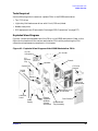
Tools Required. . . . . . . . . . . . . . . . . . . . . . . . . . . . . . . . . . . . . . . . . . . . 83
Exploded View Diagram . . . . . . . . . . . . . . . . . . . . . . . . . . . . . . . . . . . . 83
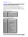
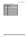
Exchange and Non-Exchange Part Numbers . . . . . . . . . . . . . . . . . . . . . 84
FRU Removal and Replacement . . . . . . . . . . . . . . . . . . . . . . . . . . . . . . . 86
Front Panel . . . . . . . . . . . . . . . . . . . . . . . . . . . . . . . . . . . . . . . . . . . . . . 87
Left Side Panel . . . . . . . . . . . . . . . . . . . . . . . . . . . . . . . . . . . . . . . . . . . 88
Power Switch/LCD Assembly . . . . . . . . . . . . . . . . . . . . . . . . . . . . . . . . 90
Removable Media Devices . . . . . . . . . . . . . . . . . . . . . . . . . . . . . . . . . . 91
Hard Disk Drives . . . . . . . . . . . . . . . . . . . . . . . . . . . . . . . . . . . . . . . . 104
6
Contents
I/O Cards. . . . . . . . . . . . . . . . . . . . . . . . . . . . . . . . . . . . . . . . . . . . . . . .110
Battery . . . . . . . . . . . . . . . . . . . . . . . . . . . . . . . . . . . . . . . . . . . . . . . . .113
Memory DIMMs . . . . . . . . . . . . . . . . . . . . . . . . . . . . . . . . . . . . . . . . . .114
Power Supply . . . . . . . . . . . . . . . . . . . . . . . . . . . . . . . . . . . . . . . . . . . .119
Voltage Regulator Modules . . . . . . . . . . . . . . . . . . . . . . . . . . . . . . . . .121
Fans . . . . . . . . . . . . . . . . . . . . . . . . . . . . . . . . . . . . . . . . . . . . . . . . . . . .124
Speaker . . . . . . . . . . . . . . . . . . . . . . . . . . . . . . . . . . . . . . . . . . . . . . . . .127
System Board Tray Assembly . . . . . . . . . . . . . . . . . . . . . . . . . . . . . . .129
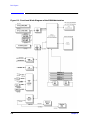
5. Block Diagram
. . . . . . . . . . . . . . . . . . . . . . . . . . . . . . . . . . . . . . . . . . . . . . . . . . . . . . . . .134
6. Boot Console Handler
Chapter Overview . . . . . . . . . . . . . . . . . . . . . . . . . . . . . . . . . . . . . . . . . .136
Boot Console Handler Features . . . . . . . . . . . . . . . . . . . . . . . . . . . . . . .137
Accessing the Boot Console Handler . . . . . . . . . . . . . . . . . . . . . . . . . . .142
Booting the Workstation . . . . . . . . . . . . . . . . . . . . . . . . . . . . . . . . . . . . .144
Searching for Bootable Media . . . . . . . . . . . . . . . . . . . . . . . . . . . . . . . . .146
Resetting the Workstation . . . . . . . . . . . . . . . . . . . . . . . . . . . . . . . . . . .147
Displaying and Setting Paths . . . . . . . . . . . . . . . . . . . . . . . . . . . . . . . . .148
Displaying and Setting the Monitor Type . . . . . . . . . . . . . . . . . . . . . . .150
The Monitor Command . . . . . . . . . . . . . . . . . . . . . . . . . . . . . . . . . . . .150
Displaying the Current Monitor Configuration . . . . . . . . . . . . . . . . .151
Setting the Monitor Type . . . . . . . . . . . . . . . . . . . . . . . . . . . . . . . . . . .151
Setting the Monitor Type with SAM . . . . . . . . . . . . . . . . . . . . . . . . . .152
Setting the Monitor Type at Power On . . . . . . . . . . . . . . . . . . . . . . . .154
Troubleshooting Monitor Problems . . . . . . . . . . . . . . . . . . . . . . . . . . .155
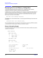
Displaying the Current Memory Configuration. . . . . . . . . . . . . . . . . . .156
Memory Information Sample. . . . . . . . . . . . . . . . . . . . . . . . . . . . . . . .156
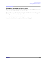
Displaying the Status of the I/O Slots . . . . . . . . . . . . . . . . . . . . . . . . . .157
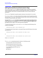
Setting the Auto Boot and Auto Search Flags . . . . . . . . . . . . . . . . . . . .158
Displaying and Setting the Security Mode . . . . . . . . . . . . . . . . . . . . . .159
7
Contents
Displaying and Setting Fastboot Mode . . . . . . . . . . . . . . . . . . . . . . . . .
Displaying the LAN Station Address . . . . . . . . . . . . . . . . . . . . . . . . . .
Displaying System Information. . . . . . . . . . . . . . . . . . . . . . . . . . . . . . .
Displaying PIM Information . . . . . . . . . . . . . . . . . . . . . . . . . . . . . . . . .
Stable Storage . . . . . . . . . . . . . . . . . . . . . . . . . . . . . . . . . . . . . . . . . . . .
ISL Environment . . . . . . . . . . . . . . . . . . . . . . . . . . . . . . . . . . . . . . . . . .
Invoking ISL from the Boot Console Handler . . . . . . . . . . . . . . . . . .
ISL User Commands. . . . . . . . . . . . . . . . . . . . . . . . . . . . . . . . . . . . . .
Obtaining and Updating System Firmware . . . . . . . . . . . . . . . . . . . . .
160
161
162
162
162
163
163
164
165
A. Product Specifications
Environmental Specifications . . . . . . . . . . . . . . . . . . . . . . . . . . . . . . . .
Altitude . . . . . . . . . . . . . . . . . . . . . . . . . . . . . . . . . . . . . . . . . . . . . . . .
DC Magnetic Field Interference. . . . . . . . . . . . . . . . . . . . . . . . . . . . .
Electromagnetic Compatibility (EMC). . . . . . . . . . . . . . . . . . . . . . . .
Temperature . . . . . . . . . . . . . . . . . . . . . . . . . . . . . . . . . . . . . . . . . . . .
Humidity (Non-condensing) . . . . . . . . . . . . . . . . . . . . . . . . . . . . . . . .
Leakage Current . . . . . . . . . . . . . . . . . . . . . . . . . . . . . . . . . . . . . . . . .
Shock . . . . . . . . . . . . . . . . . . . . . . . . . . . . . . . . . . . . . . . . . . . . . . . . . .
Vibration . . . . . . . . . . . . . . . . . . . . . . . . . . . . . . . . . . . . . . . . . . . . . . .
Electrical Specifications . . . . . . . . . . . . . . . . . . . . . . . . . . . . . . . . . . . . .
Input Power . . . . . . . . . . . . . . . . . . . . . . . . . . . . . . . . . . . . . . . . . . . . .
Line Power. . . . . . . . . . . . . . . . . . . . . . . . . . . . . . . . . . . . . . . . . . . . . .
168
168
168
168
168
168
168
168
168
169
169
169
B. Regulatory and Safety Statements
Appendix Overview . . . . . . . . . . . . . . . . . . . . . . . . . . . . . . . . . . . . . . . .
Declaration of Conformity . . . . . . . . . . . . . . . . . . . . . . . . . . . . . . . . . . .
Emissions Regulations . . . . . . . . . . . . . . . . . . . . . . . . . . . . . . . . . . . . . .
For FCC B Applications . . . . . . . . . . . . . . . . . . . . . . . . . . . . . . . . . . .
Third-Party Emissions Regulations Compliance . . . . . . . . . . . . . . . . .
172
173
174
174
176
8
Contents
Special Regulatory and Safety Information . . . . . . . . . . . . . . . . . . . . . .176
Acoustics . . . . . . . . . . . . . . . . . . . . . . . . . . . . . . . . . . . . . . . . . . . . . . . .176
Laser Safety Statement (U.S.A. Only). . . . . . . . . . . . . . . . . . . . . . . . .176
LEDs . . . . . . . . . . . . . . . . . . . . . . . . . . . . . . . . . . . . . . . . . . . . . . . . . . .176
Electrostatic Discharge (ESD) Precautions . . . . . . . . . . . . . . . . . . . . . .177
Warnings . . . . . . . . . . . . . . . . . . . . . . . . . . . . . . . . . . . . . . . . . . . . . . . . .178
C. Related Documentation
HP CE Training CD-ROM . . . . . . . . . . . . . . . . . . . . . . . . . . . . . . . . . .180
Service Manuals . . . . . . . . . . . . . . . . . . . . . . . . . . . . . . . . . . . . . . . . . .180
User Manual . . . . . . . . . . . . . . . . . . . . . . . . . . . . . . . . . . . . . . . . . . . . .180
Glossary
9
Contents
10
Figures
Figure 1-1. Front Panel Components . . . . . . . . . . . . . . . . . . . . . . . . . . . . . . . . . . . . . . . . . . 18
Figure 1-2. LCD Symbols . . . . . . . . . . . . . . . . . . . . . . . . . . . . . . . . . . . . . . . . . . . . . . . . . . . 18
Figure 1-3. CD Drive Features . . . . . . . . . . . . . . . . . . . . . . . . . . . . . . . . . . . . . . . . . . . . . . 19
Figure 1-4. Floppy Disk Drive Features. . . . . . . . . . . . . . . . . . . . . . . . . . . . . . . . . . . . . . . . 21
Figure 1-5. Rear Panel Components. . . . . . . . . . . . . . . . . . . . . . . . . . . . . . . . . . . . . . . . . . . 22
Figure 1-6. Audio Connectors . . . . . . . . . . . . . . . . . . . . . . . . . . . . . . . . . . . . . . . . . . . . . . . . 25
Figure 1-7. Security Loop Components . . . . . . . . . . . . . . . . . . . . . . . . . . . . . . . . . . . . . . . . 26
Figure 1-8. Closed Left Side Panel . . . . . . . . . . . . . . . . . . . . . . . . . . . . . . . . . . . . . . . . . . . . 26
Figure 2-1. CD Drive Jumper Setting (Rear View) . . . . . . . . . . . . . . . . . . . . . . . . . . . . . . . 37
Figure 2-2. Memory Slot Numbers and Loading Sequence . . . . . . . . . . . . . . . . . . . . . . . . 38
Figure 2-3. PCI Card Slot Numbering and Capabilities . . . . . . . . . . . . . . . . . . . . . . . . . . . 39
Figure 3-1. Main (Power on LCD) Troubleshooting Flowchart. . . . . . . . . . . . . . . . . . . . . . 43
Figure 3-2. Console Troubleshooting Flowchart . . . . . . . . . . . . . . . . . . . . . . . . . . . . . . . . . 44
Figure 3-3. Bootable Device Troubleshooting Flowchart . . . . . . . . . . . . . . . . . . . . . . . . . . 45
Figure 3-4. HP-UX Troubleshooting Flowchart . . . . . . . . . . . . . . . . . . . . . . . . . . . . . . . . . 46
Figure 3-5. Fan Locations . . . . . . . . . . . . . . . . . . . . . . . . . . . . . . . . . . . . . . . . . . . . . . . . . . . 49
Figure 4-1. Exploded View Diagram of the B2000 Workstation FRUs . . . . . . . . . . . . . . . 83
Figure 4-2. Opening the Front Panel . . . . . . . . . . . . . . . . . . . . . . . . . . . . . . . . . . . . . . . . . . 87
Figure 4-3. Opening the Left Side Panel . . . . . . . . . . . . . . . . . . . . . . . . . . . . . . . . . . . . . . . 88
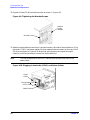
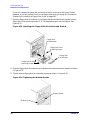
Figure 4-4. Removing the Power Switch/LCD Assembly . . . . . . . . . . . . . . . . . . . . . . . . . . 90
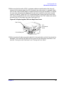
Figure 4-5. Removing the CD Drive Bay’s Rear Cover . . . . . . . . . . . . . . . . . . . . . . . . . . . . 91
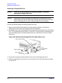
Figure 4-6. Front of the Workstation with the Front Panel Removed . . . . . . . . . . . . . . . . 92
Figure 4-7. Removing the CD Drive . . . . . . . . . . . . . . . . . . . . . . . . . . . . . . . . . . . . . . . . . . . 92
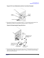
Figure 4-8. Installing the CD Drive . . . . . . . . . . . . . . . . . . . . . . . . . . . . . . . . . . . . . . . . . . . 93
Figure 4-9. Tightening the Bracket Screws . . . . . . . . . . . . . . . . . . . . . . . . . . . . . . . . . . . . . 94
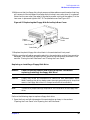
Figure 4-10. Plugging in the Audio, ATAPI, and Power Cables . . . . . . . . . . . . . . . . . . . . . 94
Figure 4-11. Replacing the CD Drive Bay’s Rear Cover . . . . . . . . . . . . . . . . . . . . . . . . . . . 95
Figure 4-12. Removing the Floppy Disk Drive Bay’s Rear Cover . . . . . . . . . . . . . . . . . . . . 96
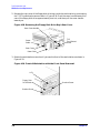
Figure 4-13. Front of Workstation with the Front Panel Removed . . . . . . . . . . . . . . . . . . 97
Figure 4-14. Removing the Floppy Disk Drive . . . . . . . . . . . . . . . . . . . . . . . . . . . . . . . . . . 97
Figure 4-15. Installing the Floppy Disk Drive Blank and Bracket . . . . . . . . . . . . . . . . . . 98
Figure 4-16. Tightening the Bracket Screws . . . . . . . . . . . . . . . . . . . . . . . . . . . . . . . . . . . . 98
Figure 4-17. Replacing the Floppy Disk Drive Bay’s Rear Cover . . . . . . . . . . . . . . . . . . . . 99
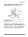
Figure 4-18. Removing the Floppy Disk Drive Bay’s Rear Cover . . . . . . . . . . . . . . . . . . . 100
Figure 4-19. Front of Workstation with the Front Panel Removed . . . . . . . . . . . . . . . . . 100
Figure 4-20. Removing the Floppy Disk Drive Bracket and Blank . . . . . . . . . . . . . . . . . 101
Figure 4-21. Installing the Floppy Disk Drive. . . . . . . . . . . . . . . . . . . . . . . . . . . . . . . . . . 102
Figure 4-22. Tightening the Bracket Screws . . . . . . . . . . . . . . . . . . . . . . . . . . . . . . . . . . . 102
Figure 4-23. Plugging in the Power and Data Cables . . . . . . . . . . . . . . . . . . . . . . . . . . . . 103
11
Figures
Figure 4-24. Replacing the Floppy Disk Drive Bay’s Rear Cover . . . . . . . . . . . . . . . . . . . 103
Figure 4-25. Location of the Hard Disk Drives. . . . . . . . . . . . . . . . . . . . . . . . . . . . . . . . . . 105
Figure 4-26. Removing the Hard Disk Drive . . . . . . . . . . . . . . . . . . . . . . . . . . . . . . . . . . . 105
Figure 4-27. Removing the Hard Disk Drive from Its Bracket . . . . . . . . . . . . . . . . . . . . . 106
Figure 4-28. Replacing the Hard Disk Drive Bracket . . . . . . . . . . . . . . . . . . . . . . . . . . . . 106
Figure 4-29. Location of the Hard Disk Drives. . . . . . . . . . . . . . . . . . . . . . . . . . . . . . . . . . 107
Figure 4-30. Removing the T-15 Torx Mounting Screws . . . . . . . . . . . . . . . . . . . . . . . . . . 108
Figure 4-31. Positioning the Bracket on to the Hard Disk Drive . . . . . . . . . . . . . . . . . . . 108
Figure 4-32. Mounting the Bracket on to the Hard Disk Drive. . . . . . . . . . . . . . . . . . . . . 108
Figure 4-33. Positioning the Hard Disk Drive Assembly . . . . . . . . . . . . . . . . . . . . . . . . . . 109
Figure 4-34. PCI Card Slot Numbering and Capabilities . . . . . . . . . . . . . . . . . . . . . . . . . 110
Figure 4-35. B2000 System Label . . . . . . . . . . . . . . . . . . . . . . . . . . . . . . . . . . . . . . . . . . . . 110
Figure 4-36. I/O Slot Numbering . . . . . . . . . . . . . . . . . . . . . . . . . . . . . . . . . . . . . . . . . . . . . 111
Figure 4-37. Removing the I/O Card . . . . . . . . . . . . . . . . . . . . . . . . . . . . . . . . . . . . . . . . . . 112
Figure 4-38. Location of the Real Time Clock Module . . . . . . . . . . . . . . . . . . . . . . . . . . . . 113
Figure 4-39. System Board View . . . . . . . . . . . . . . . . . . . . . . . . . . . . . . . . . . . . . . . . . . . . . 114
Figure 4-40. DIMM Connectors on the System Board . . . . . . . . . . . . . . . . . . . . . . . . . . . . 114
Figure 4-41. Removing Memory Cards . . . . . . . . . . . . . . . . . . . . . . . . . . . . . . . . . . . . . . . . 115
Figure 4-42. System Board View . . . . . . . . . . . . . . . . . . . . . . . . . . . . . . . . . . . . . . . . . . . . . 116
Figure 4-43. Memory Slot Numbers and Loading Sequence . . . . . . . . . . . . . . . . . . . . . . . 116
Figure 4-44. B2000 System Label . . . . . . . . . . . . . . . . . . . . . . . . . . . . . . . . . . . . . . . . . . . . 117
Figure 4-45. Installing a DIMM Card . . . . . . . . . . . . . . . . . . . . . . . . . . . . . . . . . . . . . . . . . 117
Figure 4-46. Screws Holding the Power Supply in Place . . . . . . . . . . . . . . . . . . . . . . . . . . 119
Figure 4-47. Screws Holding the Power Supply in Place . . . . . . . . . . . . . . . . . . . . . . . . . . 121
Figure 4-48. The Voltage Regulator Modules . . . . . . . . . . . . . . . . . . . . . . . . . . . . . . . . . . . 122
Figure 4-49. Master and Slave Voltage Regulator Modules. . . . . . . . . . . . . . . . . . . . . . . . 123
Figure 4-50. Fan Locations . . . . . . . . . . . . . . . . . . . . . . . . . . . . . . . . . . . . . . . . . . . . . . . . . 124
Figure 4-51. Removing the Air Divider . . . . . . . . . . . . . . . . . . . . . . . . . . . . . . . . . . . . . . . . 125
Figure 4-52. Removing the I/O Fan from the Bracket . . . . . . . . . . . . . . . . . . . . . . . . . . . . 125
Figure 4-53. Location of the Speaker . . . . . . . . . . . . . . . . . . . . . . . . . . . . . . . . . . . . . . . . . 127
Figure 4-54. Removing the Air Divider . . . . . . . . . . . . . . . . . . . . . . . . . . . . . . . . . . . . . . . . 127
Figure 4-55. Removing the Speaker from the Mounting Bracket . . . . . . . . . . . . . . . . . . . 128
Figure 4-56. Screws Holding the System Board Tray Assembly in Place . . . . . . . . . . . . . 130
Figure 5-1. Functional Block Diagram of the B2000 Workstation . . . . . . . . . . . . . . . . . . 134
12
Tables
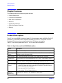
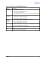
Table 1-1. Key Features of the B2000 Workstation . . . . . . . . . . . . . . . . . . . . . . . . . . . . . . . 16
Table 1-2. CD Drive Features . . . . . . . . . . . . . . . . . . . . . . . . . . . . . . . . . . . . . . . . . . . . . . . . 20
Table 1-3. Floppy Disk Drive Features. . . . . . . . . . . . . . . . . . . . . . . . . . . . . . . . . . . . . . . . . 21
Table 1-4. Serial I/O Pins . . . . . . . . . . . . . . . . . . . . . . . . . . . . . . . . . . . . . . . . . . . . . . . . . . . 23
Table 1-5. Audio Electrical Specifications . . . . . . . . . . . . . . . . . . . . . . . . . . . . . . . . . . . . . . 25
Table 3-1. Fan Numbers and Corresponding Names. . . . . . . . . . . . . . . . . . . . . . . . . . . . . . 48
Table 3-2. Chassis Codes for the B2000 Workstation . . . . . . . . . . . . . . . . . . . . . . . . . . . . . 54
Table 4-1. Exchange Part Numbers . . . . . . . . . . . . . . . . . . . . . . . . . . . . . . . . . . . . . . . . . . . 84
Table 4-2. Non-Exchange Part Numbers . . . . . . . . . . . . . . . . . . . . . . . . . . . . . . . . . . . . . . . 84
Table 6-1. System Paths . . . . . . . . . . . . . . . . . . . . . . . . . . . . . . . . . . . . . . . . . . . . . . . . . . . 148
Table 6-2. Mnemonic Style Notation for Boot Paths . . . . . . . . . . . . . . . . . . . . . . . . . . . . . 148
13
Tables
14
1 Product Information
This chapter provides general product information about the HP VISUALIZE B2000
workstation. This information is provided to help familiarize you with the main features
and components of this workstation.
15
Product Information
Chapter Overview
Chapter Overview
This chapter contains the following main sections:
• Product Description
• Front Panel Components
• Rear Panel Components
• Monitors
• Keyboard and Mouse
• Operating System Overview
• Memory
Product Description
The HP VISUALIZE B2000 is an entry-level HP-UX workstation with a 400 MHz PA-RISC
processor in a mid-tower case. It supports 4 memory slots, 4 PCI (Peripheral Connect
Interface) I/O slots, and entry-level and mid-level HP VISUALIZE graphics.
Table 1-1 lists the key features of the HP VISUALIZE B2000 workstation.
Table 1-1. Key Features of the B2000 Workstation
Feature
Description
Processor
400 MHz PA-RISC processor with 1.5 MB cache
Operating
System
HP-UX version 10.20 with the 9912 Additional Core Enhancements (ACE)
software bundle (December 1999)
User Interface
HP Common Desktop Environment (CDE) graphical user interface
Compatibility
Source and binary code compatible with the B- and C-Class product families
Main Memory
Four memory slots supporting 128MB, 256MB, and 512 MB memory DIMMs.
Minimum memory configuration is 256 MB, and maximum is 2 GB.
Internal Storage
Devices
• One standard 9 GB 7200 RPM Ultra2 Wide Low-Voltage Differential
(LVD) SCSI hard disk drive; a second 9 GB 7200 RPM Ultra2 Wide LVD
SCSI hard disk drive is optional
• One standard ATAPI fast CD drive
• One optional 3.5-inch floppy disk drive
Standard
Networking
16
Ethernet IEEE 802.3, RJ45 Twisted Pair 10/100 BaseT
Chapter 1
Product Information
Chapter Overview
Table 1-1. Key Features of the B2000 Workstation
Feature
Description
Standard I/O
• Two Serial (RS-232) ports
• Two USB (Universal Serial Bus) ports
• One Parallel (IEEE 1284) port
• Four Audio ports (Line In, Line Out, Microphone In, and Headphones Out)
I/O Expansion
Capabilities
Four PCI (Peripheral Connect Interface) slots:
• Two 64-bit PCI-2X slots at 5V, 33 MHz
• Two 32-bit PCI-1X slots at 5V, 33MHz
Monitors
Currently
Supported
• 21-inch, 1280×1024 (stereo capable) color, 75 Hz, VESA
• 21-inch, 1600×1200 color, 75 Hz, VESA
• 19-inch, 1280×1024 color, 75 Hz, VESA
Graphics
• Integrated HP VISUALIZE-fxe graphics chip on the system board
• HP VISUALIZE-fxe graphics card (optional)
Keyboard
USB (Universal Serial Bus) HP keyboard
Mouse
USB (Universal Serial Bus) HP three-button mouse (standard), or
USB HP scroll-wheel mouse (optional)
Chapter 1
17
Product Information
Front Panel Components
Front Panel Components
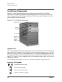
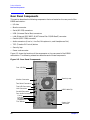
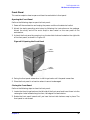
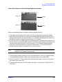
Figure 1-1 shows the components that are located on the front panel of the B2000
workstation. The following subsections describe the system LCD, power switch, and the
internal storage devices (including the standard CD drive and optional floppy disk drive)
that are located on the front panel.
Figure 1-1. Front Panel Components
System LCD
Power
Switch
CD Drive
Bay for
Optional
Floppy
Disk Drive
System LCD
The Liquid Crystal Display (LCD) is located on the left side of the front panel as part of the
power switch/LCD assembly. The LCD lights when the workstation power is on. The LCD
has a 2-line display, with up to 16-characters per line. It displays messages about the state
of the system, which are called chassis codes. See the section titled “Selftest Failures” on
page 53 in Chapter 3 for a complete listing of the possible chassis codes which can be
displayed on the LCD.
The following symbols appear on the LCD, representing different system activities.
Figure 1-2. LCD Symbols
Operating system running
Disk Access in progress
Network Receive in progress
Network Transmit in progress
18
Chapter 1
Product Information
Front Panel Components
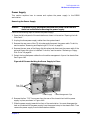
Power Switch
The power switch is also located on the left side of the front panel as part of the power
switch/LCD assembly. Use the power switch to power the workstation on and off.
When you press the power switch to power off the workstation, the operating system
executes an automatic shutdown -q command. This prevents any damage to programs
and data on the system disk.
Pressing the power switch on again automatically boots up the HP-UX operating system, if
the system has been configured to auto boot. For information on setting auto boot, refer
to the section “Setting the Auto Boot and Auto Search Flags” on page 158.
Internal Storage Devices
The B2000 workstation supports the following internal storage devices:
• Up to two hard disk drives
• One CD drive
• Optionally, one floppy disk drive
The following subsections describe these internal storage devices.
Hard Disk Drives
The B2000 workstation has one 9 GB 7200 RPM Ultra2 Wide Low-Voltage Differential
(LVD) SCSI hard disk drive as a standard component. Optionally, the workstation also
supports a second 9 GB 7200 RPM Ultra2 Wide LVD SCSI hard disk drive.
CD Drive
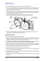
The B2000 workstation has one ATAPI fast CD drive as a standard component. Figure 1-3
shows the operating features of the CD drive, and Table 1-2 describes these features.
NOTE
The B2000 workstation supports one CD drive only.
Figure 1-3. CD Drive Features
Disk
Tray
Headphones
Jack
Chapter 1
Emergency
Eject Hole
Audio
Control
Thumbwheel
Busy
Indicator
Eject
Button
19
Product Information
Front Panel Components
Table 1-2. CD Drive Features
Feature
Purpose
Disk Tray
Holds the CD disk. (Note that this style of CD drive does not
use a disk caddy.)
Headphones Jack
Allows headphones to be connected to the CD drive for audio.
Audio Control Thumbwheel
Controls the volume of a CD disk that has audio.
Busy Indicator
Lights during a data access operation and blinks during a
data transfer. The indicator blinks initially and then stays lit
when there is one of the following.
• A defective disk
• A disk insertion error (for example, an upside down disk)
• No disk present
Eject Button
Opens the disk tray so that a CD disk may be inserted in it or
removed from it. When the CD drive is in use, press the eject
button for more than one second to open the disk tray. (Note
that the disk tray does not open if the workstation power is
off.) Then press it again to close the disk tray.
Emergency Eject Hole
Opens the disk tray when you insert a paper clip into it. Used
when the workstation does not have power and the disk tray
cannot be opened by pressing the eject button.
NOTE
20
The audio features of the CD drive are supported through applications only.
One such application is xmcd. The xmcd utility is not a part of HP-UX; it can
be downloaded from the web at this URL:
http://metalab.unc.edu/tkan/xmcd
Chapter 1
Product Information
Front Panel Components
Floppy Disk Drive (Optional)
The optional floppy disk drive is a 3.5-inch form factor device with a PC/AT interface. It
connects to the workstation via a 34-pin PC/AT ribbon cable and a 4-pin power cable. The
floppy disk drive has up to 1.44 MB capacity depending on the media and format used.
Figure 1-4 shows the features of the floppy disk drive, and Table 1-3 describes these
features.
NOTE
The B2000 workstation supports one floppy disk drive only.
Figure 1-4. Floppy Disk Drive Features
Activity LED
Eject Button
Table 1-3. Floppy Disk Drive Features
Feature
Purpose
Activity LED
Illuminates during a data access operation and
blinks during a data transfer.
Eject Button
Ejects a floppy disk from the drive when pressed.
Chapter 1
21
Product Information
Rear Panel Components
Rear Panel Components
This section describes the following components that are located on the rear panel of the
B2000 workstation:
• I/O slots
• Monitor connector
• Serial (RS-232) connectors
• USB (Universal Serial Bus) connectors
• LAN (Ethernet IEEE 802.3, RJ45 Twisted Pair 10/100 BaseT) connector
• Parallel (IEEE 1284) connector
• Audio connectors (Line In, Line Out, Microphone In, and Headphones Out)
• TOC (Transfer Of Control) button
• Security loop
• Power cord connector
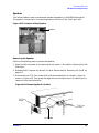
Figure 1-5 shows the locations of the components on the rear panel of the B2000
workstation. The following subsections describe each of these components.
Figure 1-5. Rear Panel Components
Four I/O Slots
Monitor Connector
Security Loop
Two Serial Connectors
Two USB Connectors
LAN Connector
USB Cable Clip
Parallel Connector
Four Audio Connectors:
Line In
Line Out
Microphone In
Headphones Out
TOC Button
22
Power Cord
Connector
Chapter 1
Product Information
Rear Panel Components
I/O Slots
The four I/O slots located at the top left of the rear panel are PCI (Peripheral Connect
Interface) slots, which can be used for add-on I/O interface cards. There are two PCI-2X
slots and two PCI-1X slots, which are defined as follows:
Slot 1: 64-bit PCI-2X at 5V, 33 MHz
Slot 2: 64-bit PCI-2X at 5V, 33 MHz
Slot 3: 32-bit PCI-1X at 5V, 33 MHz
Slot 4: 32-bit PCI-1X at 5V, 33 MHz
Monitor Connector
The B2000 workstation has an integrated HP VISUALIZE-fxe graphics chip on the system
board. Thus, the monitor connector on the rear panel of the workstation connects the
monitor to this graphics chip on the system board.
Serial Connectors
There are a variety of pointing devices (such as a mouse or trackball) or peripheral devices
(including printers, plotters, modems, and scanners) that can be attached to the two
RS-232 Serial Input/Output (SIO) ports on the rear panel of this workstation. Refer to the
label on the rear of the workstation to locate serial port 1 and serial port 2. Consult the
documentation that accompanies each pointing device or peripheral device for specific
information concerning its use.
The SIO ports are programmable, allowing functions such as bit rate, character length,
parity, and stop bits to be set. You can set these by using the HP-UX System
Administration Manager (SAM) utility, or by selecting a system special device file with the
functions already programmed. The SIO ports are used as interfaces for serial
asynchronous devices to the CPU.
Table 1-4 shows the SIO connector pin listings. The serial connectors are 9-pin D-sub
connectors. Signal names are those specified in the EIA RS-232 standard.
Table 1-4. Serial I/O Pins
Pin No.
Signal
Description
1
DCD
Data Carrier Detect
2
RXD
Receive Data
3
TXD
Transmit Data
4
DTR
Data Terminal Ready
5
GND
Ground
6
DSR
Data Set Ready
Chapter 1
23
Product Information
Rear Panel Components
Table 1-4. Serial I/O Pins
Pin No.
Signal
Description
7
RTS
Request To Send
8
CTS
Clear To Send
9
RI
Ring Indicator
USB Connectors
The USB connectors located on the rear panel of the workstation provide interfaces for the
keyboard and mouse to the system. These USB connectors support only the HP keyboard,
HP mouse, USB hub, or other HP-recommended USB devices. The keyboard and mouse
may be plugged into either USB connector on the rear of the workstation or plugged into
the USB hub. No other USB configuration is currently supported. Consult the
documentation that accompanies each USB input device for specific information
concerning its use.
NOTE
The USB HP keyboard and USB HP three-button mouse are shipped with the
B2000 workstation. The USB hub and USB HP scroll-wheel mouse may be
ordered separately.
For more information on USB, see the Universal Serial Bus website at the following URL:
http://www.usb.org
CAUTION
Use of USB devices other than those approved by HP may result in
unpredictable functionality and inferior performance of the B2000
workstation.
NOTE
The USB cable clip on the rear of the workstation (see Figure 1-5 on page 22)
provides strain relief for USB cables. To secure USB cables, open the cable
clip, loop the cables through the clip, and snap it closed.
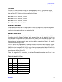
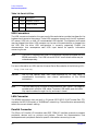
LAN Connector
The B2000 workstation has one built-in, Ethernet IEEE 802.3, RJ45 Twisted Pair (TP)
connector for 802.3 (Ethernet) or 10/100BaseT networking. The workstation automatically
selects the correct network setting.
Parallel Connector
The 25-pin HP Parallel I/O interface uses IEEE 1284 I/O interface protocols to support
peripheral devices such as printers and plotters. Consult the documentation that
accompanies each peripheral device for specific information concerning its use.
24
Chapter 1
Product Information
Rear Panel Components
Audio Connectors
The B2000 workstation has audio-input and -output capabilities through external input
and output connectors on the rear panel and through an internal speaker. The sound is
16-bit, 44 kHz (CD-quality).
As shown in Figure 1-6, the workstation’s rear panel contains four audio connectors: Line
In, Line Out, Microphone In, and Headphones Out.
Figure 1-6. Audio Connectors
Line In
Line Out
Microphone In
Headphones Out
The audio connectors are standard stereo audio mini-jacks. Hewlett-Packard recommends
using gold-plated plugs available through audio retailers for best quality recording and
playback through the external connectors.
Table 1-5 summarizes the audio electrical specifications for the B2000 workstation.
Table 1-5. Audio Electrical Specifications
Frequency Response
25 Hz to 20 kHz
Input Sensitivity/Impedance:
Line In
Microphone In
2.8Vp-p/10Kohm
40mVp-p/47Kohm
Maximum Output Level/Impedance:
Line Out
Headphones Out
2.8Vp-p/920ohm
5.6Vp-p/110ohm
TOC Button
The TOC (transfer of control) button interrupts the system and transfers control from the
default device to an auxiliary device. A transfer of control saves the state of the processor
in Processor Internal Memory (PIM) and begins execution of recovery software at a
nonzero location specified by a special location in Page Zero called MEM_TOC. The TOC
code is protected by a checksum.
Chapter 1
25
Product Information
Rear Panel Components
Security Loop
There is also a security loop on the rear panel of the B2000 workstation. The security loop
allows you to lock the workstation’s left side panel, thus securing the internal components
of the workstation. Figure 1-7 provides a view of the security loop.
Figure 1-7. Security Loop Components
Security
Loop Pin
Hole
Security
Loop Pin
and Spring
To lock the workstation’s left side panel, follow these steps:
1. Make sure the workstation’s left side panel is closed, as shown in Figure 1-8.
Figure 1-8. Closed Left Side Panel
Workstation’s
Front Panel
Left Side Panel
(Using the Front
Panel as Reference)
26
Chapter 1
Product Information
Monitors
2. Push the security loop’s pin into the security loop pin hole, and insert the padlock’s latch
through the holes at the top and bottom of the security loop. This locks the left side
panel.
3. Lock the padlock. The workstation’s left side panel is now secure.
Power Cord Connector
Plug the workstation’s power cord into the power cord connector to provide AC power to
the system.
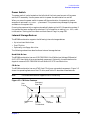
Monitors
The B2000 workstation supports monitors set to one of the following resolutions:
• 1280×1024 color (stereo capable), 75Hz, VESA
• 1600×1200 color, 75Hz, VESA
• 1280×1024 color, 75 Hz, VESA
The workstation must have either an HP-supported monitor running at 75 Hz with a
1280×1024 resolution, or a full multi-mode color monitor. Monitors with EVC, D-Sub, or 5
BNC connectors (RGB, vertical sync, horizontal sync) will function.
NOTE
The HP VISUALIZE-fxe graphics card will not function with older HP monitor
types that use a sync on green signal. This includes monitors such as the
HP 1097A/B/C/D, A2088A, and A2828A/B that only have 3 BNC connectors.
Note that you can connect the B2000 workstation to earlier HP monitors with 15-pin
miniature D-Sub cables using the A4168A adapter shipped with the workstation’s
accessory kit.
Before using a monitor, you should become familiar with its controls, connectors, and
indicators. For information about using a monitor, see the documentation that came with
the monitor.
Chapter 1
27
Product Information
Keyboard and Mouse
Keyboard and Mouse
USB HP Keyboard
The HP VISUALIZE B2000 workstation supports a USB HP keyboard. The keyboard
shipped with the workstation provides a localized PC-104, PC-105, PC-106, or JIS-109
compatible input device for USB-equipped PA-RISC workstations and other
USB-compatible computers that support the HP-UX operating system. The keyboard
includes a captive cable terminated in a USB Style A connector.
The USB keyboard is designed specifically for use with HP workstations. All keyboard
models with the exception of the JIS-109 layout may also be compatible with conventional
personal computers.
Some applications may expect to use keycodes generated by keys existing on other types of
keyboards. Consult the documentation that accompanies each input device for specific
information concerning its use.
NOTE
HIL and PS/2 devices are not supported by the B2000 workstation.
USB HP Mouse
The HP VISUALIZE B2000 workstation supports a USB HP mouse. The USB HP
three-button mouse is standard, whereas the USB HP scroll-wheel mouse is optional.
For general information on the various cursor shapes associated with different areas of HP
CDE while using a mouse, see the Using Your HP Workstation manual.
28
Chapter 1
Product Information
Operating System Overview
Operating System Overview
The B2000 workstation runs the HP-UX operating system version 10.20 with the 9912
Additional Core Enhancements (ACE) software bundle (December 1999). To verify which
version of the operating system is running on a B2000 workstation, use the command
swlist in a terminal window. Note that the ACE software bundle releases are also
available at the following URL:
http://software.hp.com/
The B2000 workstation is an Instant Ignition system (that is, a system with preloaded
software). It has X-Windows, HP’s graphical user interface, and HP CDE (Common
Desktop Environment) already installed and configured. If the Instant Ignition system
does not have the kernel preconfigured with all of the required device drivers, refer to the
Managing Systems and Workgroups manual to configure the kernel. If you have any
questions about Instant Ignition, refer to the Using Your HP Workstation manual.
Note that you can find both of the manuals mentioned in the previous paragraph on HP’s
documentation website at the following URL:
http://www.docs.hp.com/
Chapter 1
29
Product Information
Memory
Memory
The B2000 workstation has four slots for memory DIMMs. You can install only 128 MB,
256 MB, or 512 MB DIMMs in these slots. The minimum memory configuration for a
B2000 workstation is 256 MB, and the maximum is 2 GB.
To install memory DIMMs, refer to “Replacing or Installing Additional Memory DIMMs”
on page 115.
CAUTION
If memory is installed improperly or is defective, the B2000 workstation’s
operating system will not boot-up, and a DIMM error chassis code will appear
in the LCD. If an error does occur, refer to Chapter 3, “Troubleshooting.”
Memory Failures
The HP VISUALIZE B2000 system (with HP-UX 10.20 and later) uses Memory Page
Deallocation, a feature that allows the system to provide information to the operating
system about memory failures.
You can use the memrpt command with the detail switch to obtain information about the
Memory Page Deallocation Table (PDT) as well as single bit errors logged by the system,
by typing the following:
# /usr/sbin/sysdiag Enter
DUI>logtool Enter
LOGTOOL>memrpt detail
Enter
The PDT can also be checked using the pdt command in the Service menu of the Boot
Console Handler (refer to Chapter 6). If you replace a defective DIMM, use the Service
Menu’s pdt clear command to clear out the PDT.
30
Chapter 1
2 Configuration
This chapter provides details about setting up and changing the workstation and system
hardware configuration for the HP VISUALIZE B2000 workstation.
31
Configuration
Chapter Overview
Chapter Overview
This chapter contains the following main sections:
• Workstation Configurations
• System Hardware Configurations
— Internal Storage Devices
— Memory
— I/O Cards
— Monitor-Type Selection
Workstation Configurations
Refer to the HP Workstations website for a complete list of supported accessories,
peripherals, and operating system versions for the HP VISUALIZE B2000 workstation. The
URL for the website is:
http://hp.unixworkstations.com
System Hardware Configurations
This section provides information for setting up or changing the configuration of the Field
Replaceable Units (FRUs) for the B2000 workstation.
Internal Storage Devices
Hard Disk Drive Configuration
The SCSI IDs for hard disk drives are hard-wired into the SCA Ultra2 Wide LVD SCSI
interfaces on the system board within the B2000 workstation. Hence, SCSI IDs do not need
to be set for the hard disk drives (up to two) installed in this workstation. From top to
bottom, the pre-set SCSI IDs for hard disk drives are: 6 and 5.
Similarly, no jumpers are installed at the factory, nor is any jumper installation required at
the customer’s site, on the hard disk drive model supported with the B2000 workstation.
To remove and replace or install a hard disk drive, see the section titled “Hard Disk
Drives” on page 104. Also see the next subsection, “Configuring a Hard Disk Drive as a File
System,” when removing or installing a hard disk drive.
32
Chapter 2
Configuration
System Hardware Configurations
Configuring a Hard Disk Drive as a File System
This section describes how to use SAM to add a hard disk drive to the workstation as a file
system and how to remove the hard disk drive from the workstation. For more information
about configuring a hard disk drive, refer to the Managing Systems and Workgroups
manual.
The procedures in this section require you to log in as root. If you cannot log in as root,
contact the system administrator.
Adding a Hard Disk Drive as a File System
To add a hard disk drive as a file system using SAM, do the following:
1. Log in as root.
2. Move the mouse pointer to the Application Manager control for tools and click the left
mouse button. Alternatively you can execute sam at a terminal window command
prompt and skip to step 5.
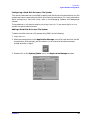
3. Double-click on the System_Admin icon in the Application Manager window.
Chapter 2
33
Configuration
System Hardware Configurations
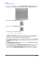
4. Double-click on the Sam icon in the Application Manager -- System_Admin window.
If you are root, the System Application Manager (SAM) will appear on the screen.
5. Double-click on the Disks and File Systems icon.
6. Double-click on the Disk Devices icon.
The following screen message is displayed:
Scanning the system’s hardware...
The Disk and File Systems window opens containing a list of drives installed in this
workstation. From the list of devices, choose the hard disk drive you would like to
configure as a file system by clicking on the device to highlight it.
7. Click on Add in the Actions menu. For this example you will select the item Not Using
the Logical Volume Manager. However, you can select any appropriate item from the
Actions menu.
8. Enter the mount directory name (for example, /disk1) in the Mount Directory field of
the Add Disk without LVM window.
9. Click on the OK button in the Add Disk without LVM window. You will need to wait
for a short time before the new file system is created and the hard disk drive is
mounted. When the Add Disk without LVM window disappears and HFS appears in
the Use column of the Disk and File Systems window, your task will be complete.
34
Chapter 2
Configuration
System Hardware Configurations
Removing a Hard Disk Drive as a File System
To remove a hard disk drive as a file system using SAM, do the following:
1. Log in as root.
2. Move the mouse pointer to the Application Manager control for tools and click the left
mouse button. Alternatively you can execute sam at a terminal window command
prompt and skip to step 5.
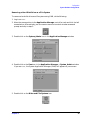
3. Double-click on the System_Admin icon in the Application Manager window.
4. Double-click on the Sam icon in the Application Manager -- System_Admin window.
If you are root, the System Application Manager (SAM) will appear on your screen.
5. Double-click on the Disks and File Systems icon.
Chapter 2
35
Configuration
System Hardware Configurations
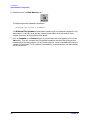
6. Double-click on the Disk Devices icon.
The following screen message is displayed:
Scanning the system’s hardware...
The Disk and File Systems window opens containing a list of devices installed in this
workstation. From the list of devices, choose the hard disk drive you would like to
remove (unmount) by highlighting that device.
7. Click on Remove in the Actions menu. In the window that next appears, click on the
Yes button. This will unmount the file system located on the hard disk drive you are
removing from the workstation. You will need to wait for a short time before the new file
system is unmounted. The file system is successfully unmounted when you see Unused
in the Use column.
36
Chapter 2
Configuration
System Hardware Configurations
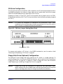
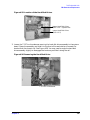
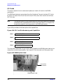
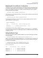
CD Drive Configuration
The CD drive connects to the ATAPI (IDE) interface in the CD drive bay backplane within
the B2000 workstation via a 40-pin ribbon cable, a 4-pin audio cable, and a 4-pin power
cable. No interface addressing is required for the CD drive.
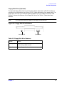
However, as shown in Figure 2-1, the CD drive should have a jumper set on the CSEL
(Cable Select) selection pins. (The CD drive should ship from the factory already jumpered
for CSEL.)
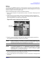
CAUTION
CD drives are susceptible to mechanical and electrostatic shock. When
handling the drive, always wear the static-grounding wrist strap that came in
the CD drive kit. Always handle the drive carefully.
Figure 2-1. CD Drive Jumper Setting (Rear View)
Jumpered for CSEL
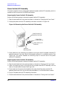
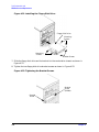
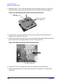
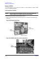
To remove and replace a CD drive in the B2000 workstation, see the section titled
“Removing and Replacing a CD Drive” on page 91.
Floppy Disk Drive (Optional) Configuration
The optional 3.5-inch floppy disk drive requires no ID, switch, or jumper settings. To
remove a floppy disk drive from the B2000 workstation, see the section titled “Removing a
Floppy Disk Drive” on page 96. To replace or install a floppy disk drive, see the section
titled “Replacing or Installing a Floppy Disk Drive” on page 99.
CAUTION
Chapter 2
Floppy disk drives are susceptible to mechanical and electrostatic shock.
When handling the drive, always wear the static-grounding wrist strap that
came in the floppy disk drive kit. Always handle the drive carefully.
37
Configuration
System Hardware Configurations
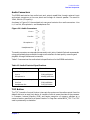
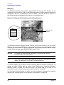
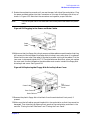
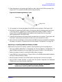
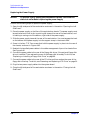
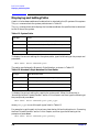
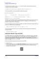
Memory
The B2000 workstation has 4 memory slots, labeled SL0 through SL3. Memory can be
configured from 256 MB to 2 GB for the B2000 workstation. Memory does not have to be
configured in pairs for the B2000, but must be loaded in the order shown in Figure 2-2.
Notice the alternating load pattern by location on the system board.
Figure 2-2. Memory Slot Numbers and Loading Sequence
SL0
Load 1st
SL3
Load 4th
SL1
Load 2nd
SL2
Load 3rd
Memory Slots
(4 Slots)
The B2000 workstation supports 128 MB, 256 MB, and 512 MB DIMMs. If you will install
different sizes of memory DIMMs in a particular workstation, load the largest size first
and then the smaller size for maximum performance. For example, load a 256 MB DIMM
in slot 0 (SL0) and then load a 128 MB DIMM in slot 1 (SL1).
CAUTION
The memory DIMMs must be installed in the correct order, else the
workstation will not boot properly.
NOTE
Users who wish to achieve both maximum performance and maximum future
capacity are advised to use 512 MB DIMMs exclusively.
To remove DIMMs, see the section titled “Removing Memory DIMMs” on page 114. To
replace or install DIMMs, see the section titled “Replacing or Installing Additional
Memory DIMMs” on page 115. Note that there is a system label on the floor of the
workstation’s interior showing the memory loading order for the B2000.
Use the Boot Console Handler to verify that the workstation recognizes the installed
memory. See “Displaying the Current Memory Configuration” on page 156.
38
Chapter 2
Configuration
System Hardware Configurations
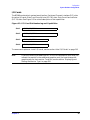
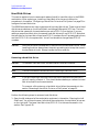
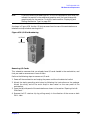
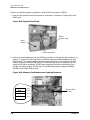
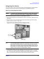
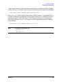
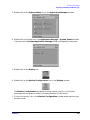
I/O Cards
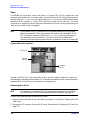
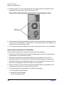
The B2000 workstation’s system board has four Peripheral Connect Interface (PCI) slots
for option I/O cards. Slots 1 and 2 are full-size (PCI-2X) slots. Slots 3 and 4 are half-size
(PCI-1X) slots. See Figure 2-3 for a brief description of slot capabilities.
Figure 2-3. PCI Card Slot Numbering and Capabilities
Slot 1
64-bits, 5V, 33MHz
Slot 2
64-bits, 5V, 33MHz
Slot 3
32-bits, 5V, 33MHz
Slot 4
32-bits, 5V, 33MHz
To remove and replace or install I/O cards, see the section titled “I/O Cards” on page 110.
NOTE
Chapter 2
If you are installing an additional HP VISUALIZE-fxe graphics card, after you
connect the monitor to the additional graphics card, you must change the
graphics path for that monitor. To do this, see the section “Displaying and
Setting the Monitor Type” on page 150.
39
Configuration
System Hardware Configurations
Monitor-Type Selection
The B2000 workstation supports monitors set to one of the following resolutions:
• 1280×1024 color (stereo capable), 75Hz, VESA
• 1600×1200 color, 75Hz, VESA
• 1280×1024 color, 75 Hz, VESA
The workstation must have either an HP-supported monitor running at 75 Hz with a
1280×1024 resolution, or a full multi-mode color monitor. Monitors with EVC, D-Sub, or 5
BNC connectors (RGB, vertical sync, horizontal sync) will function.
NOTE
The HP VISUALIZE-fxe graphics card will not function with older HP monitor
types that use a sync on green signal. This includes monitors such as the
HP 1097A/B/C/D, A2088A, and A2828A/B that only have 3 BNC connectors.
Note that you can connect the B2000 workstation to earlier HP monitors with 15-pin
miniature D-Sub cables using the A4168A adapter shipped with the workstation’s
accessory kit.
The monitor type does not have to change since the B2000 workstation is set up to
support the monitors listed above. However, if for some reason the monitor type needs to
change, refer to Chapter 6, “Boot Console Handler.”
40
Chapter 2
3 Troubleshooting
This chapter provides information about isolating a failing component, known as a Field
Replaceable Unit (FRU), in the HP VISUALIZE B2000 workstation.
41
Troubleshooting
Chapter Overview
Chapter Overview
This chapter contains the following main sections:
• Flowcharts for Troubleshooting
• Identifying LCD-Indicated Conditions
• Fan Faults and Warnings
• Dealing with a Boot Failure
• Selftest Failures
• Memory Failures
• Running System Verification Tests
• Running ODE-Based Diagnostics
• Using the PIM Dump Tool to Decode HPMCs
To troubleshoot an HP VISUALIZE B2000 workstation, you must be familiar with the
HP-UX operating system. You should also be familiar with the boot ROM diagnostics and
the Mesa (Support Tools Manager) online tests, which we describe in this chapter.
As a super-user who is troubleshooting an HP-UX system, you should be able to shutdown
and reboot a system, start and stop processes, and examine error logs. You should also be
able to use systems utilities such as ioscan to check device files and configurations,
swlist to show loaded patches and software bundles, and SAM to configure and show
enabled services and configurations. You should also be familiar with STM, the online
diagnostics tool. You can view man pages on any of these online utilities or commands.
Note any error or status messages, then run the power-up boot ROM diagnostics, known as
Self Test. If the Self Test diagnostics fail, replace the FRU that is indicated. If the tests
pass, but you still suspect a problem, run the ISL diagnostics and Mesa (Support Tools
Manager) online tests.
For a complete description of using ISL diagnostics and Mesa (Support Tools Manager),
refer to the following website URL:
http://wojo.rose.hp.com/
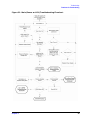
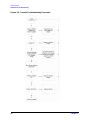
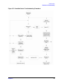
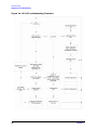
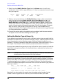
Flowcharts for Troubleshooting
The following four figures contain troubleshooting flowcharts you can follow to isolate a
failing Field Replaceable Unit (FRU). Figure 3-1 contains the main (power on LCD)
troubleshooting flowchart. Figures 3-2 through 3-4 then contain flowcharts for console,
bootable device, and HP-UX troubleshooting, respectively.
42
Chapter 3
Troubleshooting
Flowcharts for Troubleshooting
Figure 3-1. Main (Power on LCD) Troubleshooting Flowchart
Chapter 3
43
Troubleshooting
Flowcharts for Troubleshooting
Figure 3-2. Console Troubleshooting Flowchart
44
Chapter 3
Troubleshooting
Flowcharts for Troubleshooting
Figure 3-3. Bootable Device Troubleshooting Flowchart
Chapter 3
45
Troubleshooting
Flowcharts for Troubleshooting
Figure 3-4. HP-UX Troubleshooting Flowchart
46
Chapter 3
Troubleshooting
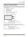
Identifying LCD-Indicated Conditions
Identifying LCD-Indicated Conditions
The B2000 workstation uses an LCD panel to display firmware/OS progress codes. The
codes, referred to as chassis codes, consist of one of the mnemonics listed below, followed by
a 4-digit hexadecimal number identifying the code module being executed. The mnemonics
and their meanings are:
FLT
A hardware error has been detected
TST
Hardware being tested
INI
Hardware being initialized
SHU
System being shutdown
WRN
A non-optimal or unusual operating condition exists
RUN
Computer is running operating system
In general, the LCD display has the following format:
FFFFFF
Line 1
DDDDDDDDDDDDDDDD
Line 2
MMM
CCCC:
MMM
Three-character chassis code mnemonic
CCCC
Four-digit hexadecimal code
FFFFFF
Six-character Field Replaceable Unit (FRU) description
DDDDDDDDDDDDDDDD Description of the chassis code
If the system encounters an FLT code while the system is booting, the FLT code is
interpreted and a message is displayed. For example, you may have information similar to
the following in the LCD:
FLT
Three-character chassis code mnemonic
30FC
Four-digit hexadecimal code
SYS BD
Six-character Field Replaceable Unit (FRU) description
bad sys bd id
Description of the chassis code
Chapter 3
47
Troubleshooting
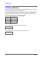
Fan Faults and Warnings
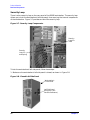
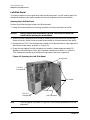
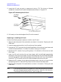
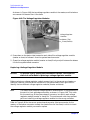
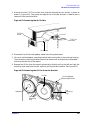
Fan Faults and Warnings
This section provides the fault (FLT) and warning (WRN) messages you will see in the LCD if
there is a problem with a fan in the B2000 workstation.
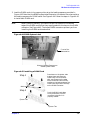
A chassis code which indicates that a fan has failed (FLT D01n) or is running too slowly
(WRN D02n) within a B2000 workstation specifies the fan number, n. Table 3-1 lists the fan
numbers and their names. To locate the correct fan, see Figure 3-5 on the next page.
Table 3-1. Fan Numbers and Corresponding Names
Fan Number (n)
Name of the Fan
2
I/O fan
4
System fan
5
Processor fan
Here is an example of a fault message for the system fan (4):
FLT D014 SYS BD
fan 4: failure!
Here is an example of a warning message for the processor fan (5):
WRN D025 SYS BD
fan 5: too slow!
48
Chapter 3
Troubleshooting
Fan Faults and Warnings
Figure 3-5. Fan Locations
I/O Fan (2)
System
Fan (4)
Processor
Fan (5)
In the case of a fan problem, you will need to replace:
• The fan itself, if it is either an I/O fan (2) or a system fan (4).
• The entire system board tray assembly, if it is a processor fan (5) (that is, the fan
mounted on the PA-RISC microprocessor on the system board).
See Chapter 4 for the procedures you should follow to remove and replace a fan.
Chapter 3
49
Troubleshooting
Dealing with a Boot Failure
Dealing with a Boot Failure
To start this workstation from an operating system stored on a device different from the
usual boot device, to boot from a different disk, or to boot from another type of device (such
as an alternate hard disk or CD), see the following situations and examples that use the
Boot Console Handler. To access the Boot Console Handler, see Chapter 6.
• To boot from a known device containing a bootable operating system, type the following
at the prompt and press Enter:
Main Menu: Enter a command or a menu > boot device
where device is the hardware path to the device, specified in Mnemonic Style Notation
For example, to boot an operating system stored on a DDS-format tape in a drive
located at “scsi.1.0,” go to the Main Menu of the Boot Console Interface and then type
the following command at the prompt and press Enter:
Main Menu: Enter a command > boot scsi.1.0
The operating system on the specified device is used to start the workstation.
• To interact with the Initial System Loader (ISL) before booting the workstation, type
the following at the prompt and press Enter:
Main Menu: Enter a command or a menu > boot device
You are prompted: Interact with ISL (Y or N) > y
Answering yes (y) causes the ISL to be loaded from the specified device. After a short
time, the following prompt appears on the screen:
ISL>
ISL is the program that actually controls the loading of the operating system. By
interacting with ISL, you can choose to load an alternate version of the HP-UX
operating system.
For example, if the usual kernel (/stand/vmunix for HP-UX 10.20) on the root disk
(scsi.6.0) has become corrupted, boot the workstation from the backup kernel
(/stand/vmunix.prev for HP-UX 10.20) by typing the following at the ISL> prompt
and press Enter:
ISL> hpux /stand/vmunix.prev
• To find the location of the bootable operating systems on the various media in the file
system, use the search ipl command.
50
Chapter 3
Troubleshooting
Dealing with a Boot Failure
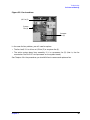
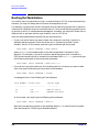
Searching for Bootable Media
To list all devices that may contain bootable media, go to the Main Menu of the Boot
Console Interface and then type the following at the prompt:
Main Menu: Enter a command or a menu > search ipl
The search may turn up more devices than there are lines on the display. If using a text
terminal, you can control the progress of the search from the terminal’s keyboard by
performing the following steps:
• To hold the display temporarily, press Ctrl S
• To continue the display, press Ctrl Q
• To halt the search, press Esc
These flow-control commands do not work with a bitmapped display, but such a display can
show more than forty lines of text, so they are unnecessary.
To search for devices of just one type that actually contain bootable media, go to the Main
Menu of the Boot Console Interface and then type the following at the prompt:
Main Menu: Enter a command > search ipl device_type
where device_type is one of the following:
• scsi is the built-in fast, Ultra2 Wide LVD (Low Voltage Differential) SCSI bus.
• lan is all connections to the built-in LAN.
• ide is the built-in CD drive.
• pcin is an optional plug-in device in PCI slot number n.
• disk is any bootable device other than LAN.
Stable Storage
Stable Storage is non-volatile memory associated with each PA-RISC processor module.
Stable storage is used by the processor (CPU) to store device path information, the state of
the boot flags, HPMC error information, and operating system initialization data.
Chapter 3
51
Troubleshooting
Dealing with a Boot Failure
Boot Command Notations
The boot command supports the following two notations:
• Mnemonic
• Path number
Type help scsi or help lan for more information on the boot path parameters.
Here are examples of mnemonic notation:
• boot with no parameters selects the primary boot path in stable storage.
• boot with the alternate or alt parameter selects the alternate boot path in stable
storage.
Here is an example of path number notation:
• boot p1 attempts to boot from the second path in a list generated by a previous search
command.
Supported Boot Paths
SCSI devices are bootable when connected to the SCSI port on the system. Diskless
workstations can only boot from the LAN port on the system board. The workstation can
be booted from the CD-ROM for software installation.
ISL Environment
The ISL environment provides the means to load the operating system (HP-UX)
environment. The ISL environment also provides an off-line platform to execute diagnostic
and utility programs from a boot device when HP-UX does not load.
The ISL program is the first program loaded into main memory from an external media
(LAN, disk, or tape) and launched by the initial program loader (IPL) routine during the
Boot Administration environment.
The ISL environment provides the following capabilities:
• Execute user-entered commands to modify boot device paths and boot options in stable
storage.
• Run off-line diagnostic programs and utilities.
• Provide automatic booting of the HP-UX operating system after power-on or reset.
The ISL program provides a stand-alone environment for loading off-line diagnostic and
utility programs from the LIF directory. The ISL program also provides user commands to
configure the boot parameters into Stable Storage.
52
Chapter 3
Troubleshooting
Selftest Failures
Selftest Failures
Chassis codes are the key to debugging selftest errors. If a failure is found during selftest,
chassis codes are displayed in the LCD. The procedure for using these codes to debug a
failure is as follows:
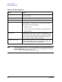
1. Using Table 3-2, which starts on the next page, find the chassis code listed on the LCD.
2. To get additional information about failures from the Boot Console Handler, use the
Service Menu’s pim, pdt, and ChassisCodes commands.
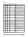
In the following table, the FRU column shows messages printed on the LCD that refer to
system FRUs. Only FLT codes have FRUs associated with them. Some WRN codes are also
device specific, especially to IODC calls; for example, 8xxx codes. TST and INI codes do not
necessarily correspond to any FRU. All codes are listed in numeric order.
NOTE
Chapter 3
Because the B2000 workstation is a single-board system, references to the
I/O BD (I/O board) in chassis codes displayed on the LCD and listed in Table
3-2 are actually references to the SYS BD (system board).
53
Troubleshooting
Selftest Failures
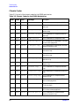
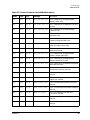
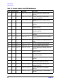
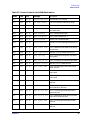
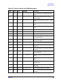
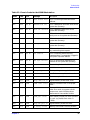
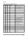
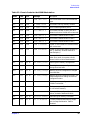
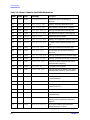
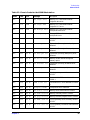
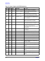
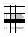
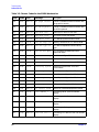
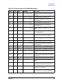
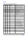
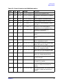
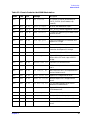
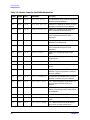
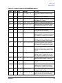
Chassis Codes
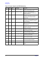
Table 3-2. lists all of the chassis codes for the B2000 workstation.
Table 3-2. Chassis Codes for the B2000 Workstation
Ostat
Code
FRU
Message
Description
FLT
1n01
SYS BD
HPMC occurred
CPU n detected an unexpected HPMC.
FLT
1n02
SYS BD
powerfail intrpt
CPU n detected an unexpected power fail
interrupt.
FLT
1n03
SYS BD
recvry cntr trap
CPU n detected an unexpected recovery
counter trap.
FLT
1n04
SYS BD
external intrrpt
CPU n detected an unexpected external
interrupt.
FLT
1n05
SYS BD
LPMC occurred
CPU n detected an unexpected LPMC.
FLT
1n06
SYS BD
ITLB mis/Ipg flt
CPU n detected an unexpected ITLB miss
or instruction page fault.
FLT
1n07
SYS BD
I mem prot trap
CPU n detected an unexpected instruction
memory protection trap.
FLT
1n08
SYS BD
illegal inst trp
CPU n detected an unexpected illegal
instruction trap.
FLT
1n09
SYS BD
break instr trap
CPU n detected an unexpected break
instruction trap.
FLT
1n0A
SYS BD
privilgd op trap
CPU n detected an unexpected privileged
operation trap.
FLT
1n0B
SYS BD
privlgd reg trap
CPU n detected an unexpected privileged
register trap.
FLT
1n0C
SYS BD
overflow trap
CPU n detected an unexpected overflow
trap.
FLT
1n0D
SYS BD
conditional trap
CPU n detected an unexpected conditional
trap.
FLT
1n0E
SYS BD
assist exep trap
CPU n detected an unexpected assist
exception trap.
FLT
1n0F
SYS BD
DTLB mis/Dpg flt
CPU n detected an unexpected DTLB
miss or data page fault.
FLT
1n10
SYS BD
non-acc ITLB mis
CPU n detected an unexpected non-access
ITLB miss fault.
FLT
1n11
SYS BD
non-acc DTLB mis
CPU n detected an unexpected non-access
DTLB miss or data page fault.
FLT
1n12
SYS BD
data mem prot tr
CPU n detected an unexpected data
memory protection trap.
54
Chapter 3
Troubleshooting
Selftest Failures
Table 3-2. Chassis Codes for the B2000 Workstation
Ostat
Code
FRU
Message
Description
FLT
1n13
SYS BD
data mem brk trp
CPU n detected an unexpected data
memory break trap.
FLT
1n14
SYS BD
TLB dirty bit tr
CPU n detected an unexpected TLB dirty
bit trap.
FLT
1n15
SYS BD
page refrnce trp
CPU n detected an unexpected page
reference trap.
FLT
1n16
SYS BD
assist emul trap
CPU n detected an unexpected assist
emulation trap.
FLT
1n17
SYS BD
hi-priv xfer trp
CPU n detected an unexpected
higher-privilege transfer trap.
FLT
1n18
SYS BD
lo-priv xfer trp
CPU n detected an unexpected
lower-privilege transfer trap.
FLT
1n19
SYS BD
taken branch trp
CPU n detected an unexpected
taken-branch trap.
FLT
1n1A
SYS BD
data mem acc rts
CPU n detected an unexpected data
memory access rights trap.
FLT
1n1B
SYS BD
data mem prot ID
CPU n detected an unexpected data
memory protection ID trap.
FLT
1n1C
SYS BD
unalign data ref
CPU n detected an unexpected unaligned
data reference trap.
FLT
1n1D
SYS BD
perf mon intrrpt
CPU n detected an unexpected
performance monitor interrupt.
TST
1n20
SYS BD
CPUn basic test
CPU n is starting its basic operations
self-test.
TST
1n21
SYS BD
CPUn alu test
CPU n is starting its arithmetic and
logical unit self-test.
TST
1n22
SYS BD
CPUn branch test
CPU n is starting its branch instruction
self-test.
TST
1n23
SYS BD
CPUn arith cond
CPU n is starting its arthimetic condition
self-test.
TST
1n24
SYS BD
CPUn bit opers
CPU n is starting its bit operation
instruction self-test.
TST
1n25
SYS BD
CPUn cntrl regs
CPU n is starting its control register
self-test.
TST
1n26
SYS BD
CPUn ext intrpt
CPU n is starting its external interrupt
self-test.
Chapter 3
55
Troubleshooting
Selftest Failures
Table 3-2. Chassis Codes for the B2000 Workstation
Ostat
Code
FRU
Message
Description
TST
1n27
SYS BD
CPUn itimer test
CPU n is starting its interval timer
self-test.
TST
1n28
SYS BD
CPUn multi-media
CPU n is starting its multi-media
instructions self-test.
TST
1n29
SYS BD
CPUn shadow reg
CPU n is starting its shadow register
self-test.
TST
1n2A
SYS BD
CPUn diagnse reg
CPU n is starting its diagnose register
self-test.
TST
1n2B
SYS BD
CPUn rdr test
CPU n is starting its remote diagnose
register self-test.
TST
1n2C
SYS BD
CPUn bypass test
CPU n is starting its integer bypass
operation self-test.
TST
1n30
SYS BD
CPUn start est
CPU n is starting its early (pre-memory)
self-tests.
WRN
1n31
SYS BD
CPUn skip est
CPU n is bypassing its early self-tests to
save time.
FLT
1n32
SYS BD
CPUn bad tst mod
CPU n detected an unsupported system
mode.
INI
1n3C
SYS BD
CPUn initialize
CPU n is initializing after self-tests.
TST
1n3E
SYS BD
CPUn exit est
CPU n finished its early self-tests.
TST
1nA0
SYS BD
CPUn fpu tests
CPU n is starting its floating-point unit
self-tests.
TST
1nA1
SYS BD
CPUn fpu reg tst
CPU n is starting its floating-point
register self-test.
TST
1nA2
SYS BD
CPUn fpu inst
CPU n is starting its floating-point
instruction self-test.
TST
1nA3
SYS BD
CPUn fpu traps
CPU n is starting its floating-point trap
self-test.
TST
1nA4
SYS BD
CPUn fpu misc
CPU n is starting its floating-point
miscellaneous operations self-test.
TST
1nA5
SYS BD
CPUn fpu bypass
CPU n is starting its floating-point
bypassing self-test.
TST
1nB1
SYS BD
CPUn TLB RAM tst
CPU n is starting its TLB register
self-test.
TST
1nB2
SYS BD
CPUn TLB trans
CPU n is starting its TLB translation
self-test.
56
Chapter 3
Troubleshooting
Selftest Failures
Table 3-2. Chassis Codes for the B2000 Workstation
Ostat
Code
FRU
Message
Description
FLT
1nBA
SYS BD
monarch CPU fail
The monarch CPU failed.
FLT
1nBB
SYS BD
bad CPUn number
The CPU identifier was out of range.
FLT
1nBF
SYS BD
CPUn halt boot
Bootstrap failure--machine halted.
INI
1nCA
SYS BD
CPUn sys bus arb
Monarch CPU is initializing the system
bus arbitration.
WRN
1nCD
SYS BD
CPUn deconfig
CPU n deconfigured itself.
WRN
1nCE
SYS BD
CPUn extinguish
PDC_PROC halted CPU n.
FLT
1nCF
SYS BD
slaven failed
Slave CPU n failed self-test.
WRN
1mDs
SYS BD
slaves deconfig
Monarch CPU m deconfigured slave CPU
s.
WRN
1nEF
SYS BD
CPUn slftst warn
CPU n detected a non-fatal error during
its self-tests.
WRN
1mFs
SYS BD
monm stop slaves
Monarch CPU m halted slave CPU s.
INI
1nFC
SYS BD
CPUn sync’ing
CPU n is synchronizing with the rest of
the system.
INI
1nFD
SYS BD
CPUn stat wd tst
CPU n is testing the system status word.
FLT
1nFF
SYS BD
monarchn selftst
Monarch CPU n failed self-test.
TST
2n20
SYS BD
CPUn icache RAM
CPU n is starting its instruction cache
RAM self-test.
FLT
2n25
SYS BD
CPUn ic ld d err
CPU n detected a data error during data
cache load.
FLT
2n26
SYS BD
CPUn ic ld t err
CPU n detected a tag error during data
cache load.
TST
2n30
SYS BD
CPUn icache tag
CPU n is starting its instruction cache tag
self-test.
TST
2n40
SYS BD
CPUn icache par
CPU n is starting its instruction cache
parity detection self-test.
TST
2n50
SYS BD
CPUn dc stor que
CPU n is starting its data cache store
queue self-test.
FLT
2n51
SYS BD
CPUn dc st q err
CPU n detected an error during its data
cache store queue self-test.
TST
2n70
SYS BD
CPUn dcache RAM
CPU n is starting its data cache RAM
self-test.
TST
2n80
SYS BD
CPUn dcache tag
CPU n is starting its data cache tag
self-test.
Chapter 3
57
Troubleshooting
Selftest Failures
Table 3-2. Chassis Codes for the B2000 Workstation
Ostat
Code
FRU
Message
Description
TST
2n90
SYS BD
CPUn dcache ECC
CPU n is starting its data cache ECC
self-test.
FLT
2BAD
SYS BD
assertion fail
A firmware assertion failed.
TST
3n00
SYS BD
ROM checksum tst
Monarch CPU n is testing the boot ROM
integrity.
FLT
3n00
SYS BD
ROM checksum BAD
The boot ROM failed checksum.
INI
3n00
SYS BD
ROM checksum ok
The boot ROM passed checksum.
TST
3n01
SYS BD
PDH control test
Monarch CPU n is testing PDH control
register.
INI
3n01
SYS BD
PDH control init
Monarch CPU n is initializing the PDH
control register.
FLT
3n01
SYS BD
PDH control err
Monarch CPU n detected an error in the
PDH control register.
TST
3n02
SYS BD
scratch RAM test
Monarch CPU n is testing scratch RAM.
INI
3n02
SYS BD
scratch RAM ok
The scratch RAM test failed.
FLT
3n02
SYS BD
scratch RAM bad
The scratch RAM test passed.
WRN
3n03
SYS BD
stbl st read err
CPU n detected a non-fatal error reading
the stable store.
FLT
3n03
SYS BD
stbl st read err
CPU n detected a non-fatal error reading
the stable store.
INI
3nC4
SYS BD
clearing EEPROM
Monarch CPU n is clearing the EEPROM.
INI
3nD4
SYS BD
deflting EEPROM2
Monarch CPU n is initializing the
EEPROM to system defaults.
WRN
3n04
SYS BD
EEPROM write err
CPU n detected a non-fatal error writing
the EEPROM.
FLT
3n04
SYS BD
EEPROM write err
CPU n detected a fatal error writing the
EEPROM.
FLT
3n05
SYS BD
EEPROM wrt limit
CPU n detected a fatal error writing the
EEPROM.
WRN
3n06
SYS BD
EEPROM read err
CPU n detected a non-fatal error reading
the EEPROM.
FLT
3n06
SYS BD
EEPROM read err
CPU n detected a fatal error reading the
EEPROM.
INI
3n07
SYS BD
CPUn invoke LDB
CPU n is starting the low-level debugger.
58
Chapter 3
Troubleshooting
Selftest Failures
Table 3-2. Chassis Codes for the B2000 Workstation
Ostat
Code
FRU
Message
Description
FLT
3n09
SYS BD
bad sys mde byte
CPU n detected an unsupported system
mode.
WRN
3n1A
SYS BD
hversion mismtch
Stable store hardware version doesn’t
match system.
TST
3n1B
SYS BD
chck model strng
Check model string with version in stable
store.
WRN
3n1B
SYS BD
model str msmtch
Model string doesn’t match that in stable
store.
FLT
3n1B
SYS BD
fatal model str
Error reading model string from stable
store.
TST
3n1C
SYS BD
test software ID
Check LANIC address.
WRN
3n1C
SYS BD
update sw ID
Update LANIC address.
FLT
3n1C
SYS BD
update sw ID err
Error updating LANIC address.
INI
3n2s
SYS BD
Invoke LDB: s
CPU n is awaiting the low-level debugger
for s more seconds.
TST
3nBC
IO BD
test sys clocks
CPU n is verifying processor clocks with
the real-time clock.
INI
3nBC
SYS BD
init sys clocks
CPU n has initialized the processor clocks.
FLT
3nBC
IO BD
RTC tick timeout
The real-time clock is ticking too slowly or
not at all.
FLT
3nCD
IO BD
RTC tick timeout
The real time clock is ticking too slowly or
not at all.
TST
3nCD
SYS BD
check defaults
CPU n is initializing stable store values to
system defaults.
INI
3nCD
SYS BD
init defaults
CPU n finished initializing stable store
values.
FLT
3nCD
SYS BD
init EEPROM err
CPU n detected an error writing to stable
store.
FLT
3nEC
SYS BD
bad sys config
CPU n detected an illegal CPU board
configuration.
FLT
3nF4
SYS BD
EEPROM boot limt
CPU n detected a fatal error writing the
EEPROM.
FLT
3nFC
SYS BD
bad sys bd id
CPU n cannot identify CPU board.
TST
4n00
SYS BD
CPUn start lst
CPU n is starting its late (with memory)
self-tests.
Chapter 3
59
Troubleshooting
Selftest Failures
Table 3-2. Chassis Codes for the B2000 Workstation
Ostat
Code
FRU
Message
Description
WRN
4n01
SYS BD
CPUn skip lst
CPU n is bypassing its late self-tests to
save time.
TST
4n0E
SYS BD
CPUn exit lst
CPU n finished its late self-tests.
TST
4n20
SYS BD
CPUn lst erly st
CPU n is re-executing some of its early
self-tests from system memory.
TST
4n21
SYS BD
CPUn lst basic
CPU n is re-executing its basic operations
self-test.
TST
4n22
SYS BD
CPUn lst alu
CPU n is re-executing its arithmetic and
logic unit self-test.
TST
4n23
SYS BD
CPUn lst branch
CPU n is re-executing its branch
instruction self-test.
TST
4n24
SYS BD
CPUn lst arth cd
CPU n is re-executing its arithmetic
conditions self-test.
TST
4n25
SYS BD
CPUn lst bit ops
CPU n is re-executing its bit operations
self-test.
TST
4n26
SYS BD
CPUn lst ctl reg
CPU n is re-executing its control register
self-test.
TST
4n27
SYS BD
CPUn lst ext int
CPU n is re-executing its external
interrupt self-test.
TST
4n28
SYS BD
CPUn lst itimer
CPU n is re-executing its interval timer
self-test.
TST
4n29
SYS BD
CPUn lst mltimed
CPU n is re-executing its multi-media
instructions self-test.
TST
4n2A
SYS BD
CPUn lst shadow
CPU n is re-executing its shadow register
self-test.
TST
4n2B
SYS BD
CPUn lst dg regs
CPU n is re-executing its diagnose
register self-test.
TST
4n2C
SYS BD
CPUn lst rdrs
CPU n is re-executing its remote diagnose
register self-test.
TST
4n2D
SYS BD
CPUn lst bypass
CPU n is re-executing its integer bypass
operation self-test.
TST
4n30
SYS BD
CPUn cache byte
CPU n is starting its data cache sub-word
operations self-test.
TST
4n40
SYS BD
CPUn cache flush
CPU n is starting its cache flush self-test.
TST
4n50
SYS BD
CPUn icache miss
CPU n is starting its instruction cache
miss self-test.
60
Chapter 3
Troubleshooting
Selftest Failures
Table 3-2. Chassis Codes for the B2000 Workstation
Ostat
Code
FRU
Message
Description
TST
4n60
SYS BD
CPUn dcache miss
CPU n is starting its data cache miss
self-test.
FLT
5n00
SYS BD
unknown bus err
CPU n detected an unknown error on the
system bus (Runway).
FLT
5n02
SYS BD
path err assertd
CPU n detected a path error on the
system bus (Runway).
FLT
5n04
SYS BD
parity error
CPU n detected a data, address, or control
parity error on the system bus (Runway).
FLT
5n07
SYS BD
Runway dir error
CPU n detected a directed error on the
system bus (Runway).
FLT
5n08
SYS BD
Runway broad err
CPU n detected a broadcast error on the
system bus (Runway).
FLT
5n0A
SYS BD
illegal response
CPU n received data that did not match
any outstanding data request.
FLT
5n0B
SYS BD
bus timeout
CPU n timed out before receiving
requested data. The responder is logged in
the system responder address.
FLT
5n0C
SYS BD
CPU sync failure
CPU n’s synchronizer detected a rule
violation on the system bus (Runway).
INI
7000
DIMM
start DIMM scan
Start looking for installed DIMMs.
INI
7002
SYS BD
init mem tables
Initialize memory data structures.
FLT
7004
SYS BD
mem plt upd fail
Error updating memory platform data.
FLT
7005
DIMM
insufficient mem
Insufficient memory detected to continue.
TST
7010
DIMM
check DIMM order
Start memory DIMM order check.
WRN
7011
DIMM
skip DIMM ord ck
Bypass memory DIMM order check.
FLT
7012
DIMM
DIMM order error
Memory DIMMs are not in the proper
order.
FLT
7013
DIMM
DIMM order error
Memory DIMMs are not in the proper
order. As a result, the system cannot
access one or more DIMMs and has
deallocated all inaccessible DIMMs.
TST
7016
DIMM
DIMM pair check
Start memory DIMM pair check (DIMMs
in a pair (e.g. 0a/0b) must match in
J7000).
WRN
7017
DIMM
skip mem pair ck
Bypass memory DIMM set check.
FLT
701F
DIMM
no memory found
Memory scan couldn’t find any DIMMs.
Chapter 3
61
Troubleshooting
Selftest Failures
Table 3-2. Chassis Codes for the B2000 Workstation
Ostat
Code
FRU
Message
Description
TST
7020
SYS BD
search for IMM
Try to find a single memory bank to use
for the initial memory module.
TST
703s
DIMM
DIMM s IMM vrfy
DIMM s was the initial memory module
last boot. Verify it still works.
FLT
704s
DIMM
DIMM s IMM fail
DIMM s failed the initial memory module
test.
TST
705s
DIMM
DIMM s IMM test
Test DIMM in slot s as the initial memory
module.
INI
706s
DIMM
DIMM s is IMM
DIMM s chosen as initial memory module.
INI
70F0
DIMM
DIMM scan done
Memory DIMM scan complete.
TST
7100
SYS BD
mem register tst
Start testing registers in memory
controller.
WRN
7101
SYS BD
skip mem reg tst
Bypass the memory controller register
test.
FLT
7102
SYS BD
mem addr reg tst
Firmware detected an error in the
memory controller address registers.
FLT
7103
SYS BD
mem mbat reg tst
Firmware detected an error in the
memory controller bank registers.
FLT
7104
SYS BD
mem reg tst fail
Firmware detected an error in the
memory controller memory registers.
FLT
7105
SYS BD
mem err reg test
Firmware detected an error in the
memory controller error registers.
FLT
7106
SYS BD
mem err clr fail
Firmware was unable to clear the error
registers after testing.
INI
7200
DIMM
strt DIMM detect
Start the Serial Presence Detection (SPD)
to search for memory DIMMs.
INI
7201
DIMM
DIMM detect x%
SPD is x% finished.
WRN
7202
SYS BD
skip DIMM detect
Bypass Serial Presence Detection.
FLT
7203
DIMM
unsupp DIMM type
SPD found an unsupported DIMM type.
FLT
7204
DIMM
SPD fatal error
SPD detected an unexpected, fatal error.
INI
7205
DIMM
add HP DIMM type
New HP manufactured DIMM type added
to tables.
INI
7206
DIMM
non-HP DIMM type
New non-HP DIMM type added to tables
(use at own risk).
62
Chapter 3
Troubleshooting
Selftest Failures
Table 3-2. Chassis Codes for the B2000 Workstation
Ostat
Code
FRU
Message
Description
FLT
7207
DIMM
DIMM table full
The DIMM table is full--cannot add new
type.
FLT
7208
DIMM
no DIMMs found
SPD didn’t find any memory DIMMs.
INI
721s
DIMM
is DIMM s inst?
SPD is checking memory slot s.
INI
722s
DIMM
???? DIMM in s
SPD found a DIMM in slot s, but can’t
determine its size. DIMM will not be used.
INI
723s
DIMM
128M DIMM in s
SPD found a 128MB DIMM in slot s.
INI
724s
DIMM
256M DIMM in s
SPD found a 256MB DIMM in slot s.
INI
725s
DIMM
512M DIMM in s
SPD found a 512MB DIMM in slot s.
FLT
72As
DIMM
DIMM s checksum
DIMM in slot s failed SPD checksum and
will not be used.
FLT
72Cs
DIMM
DIMM s mismatch
DIMM in slot s didn’t match the other in
pair. (J7000 only--DIMMs must be in
matched pairs.)
FLT
72Ds
DIMM
DIMM s load err
Memory DIMMs are not in the proper
order. As a result, the system cannot
access DIMM s and has deallocated it.
INI
7300
SYS BD
mem config start
Starting main memory configuration.
TST
7301
SYS BD
check mem config
Checking for memory configuration
change since last boot.
WRN
7302
SYS BD
mem confg changd
Memory physical configuration changed
since last boot.
INI
7303
SYS BD
use confg change
Memory physical configuration didn’t use
saved configuration change. Use stored
configuration data.
INI
7304
SYS BD
build mem intrlv
Building memory configuration with all
DIMMs interleaved.
INI
7305
SYS BD
save mem config
Saving memory configuration information
in non-volatile memory.
WRN
7306
SYS BD
use alt mem conf
Memory will be configured from fixed
values, instead of detected DIMMs.
INI
7307
SYS BD
interleve memory
Generating the memory interleave.
FLT
7308
SYS BD
PDT is disabled
Firmware detected bad memory pages,
but the Page Deallocation Table is
disabled.
Chapter 3
63
Troubleshooting
Selftest Failures
Table 3-2. Chassis Codes for the B2000 Workstation
Ostat
Code
FRU
Message
Description
FLT
7309
DIMM
insufficient mem
Insufficient error-free memory to
continue.
FLT
730C
SYS BD
mem intrlv fail
Memory interleave generation failed.
INI
730F
SYS BD
mem config done
Main memory configuration complete.
TST
7400
DIMM
non-dest mem tst
Starting non-destructive memory test.
TST
740F
DIMM
non-dst tst done
Non-destructive memory test complete.
INI
7500
SYS BD
memory reset
Resetting memory system.
WRN
7501
SYS BD
mem log clr warn
Memory error logs didn’t clear on first try.
FLT
7502
SYS BD
mem err log fail
Firmware could not clear memory error
logs.
TST
7600
DIMM
dest mem test
Starting the destructive memory test.
WRN
7601
DIMM
mem init only
Skip the test, just initialize memory to
save time.
TST
7602
DIMM
tst 1st mem page
Starting 3-pass test of first memory page.
TST
7603
DIMM
tst rest of mem
Starting 3-pass test of the rest of memory.
TST
7604
DIMM
start 1st pass
Starting 1st pass of memory test (write
pseudorandom sequence).
TST
7605
DIMM
1st pass x%
First pass is x% complete.
TST
7606
DIMM
start 2nd pass
Starting 2nd pass of memory test (verify
pseudorandom sequence, write inverse).
TST
7607
DIMM
2nd pass x%
Second pass is x% complete.
TST
7608
DIMM
start 3rd pass
Starting 3rd pass of memory test (verify
inverse sequence).
TST
7609
DIMM
3rd pass x%
Third pass is x% complete.
TST
760A
DIMM
start mem init
Starting memory initialization. (Initialize
to zero to set ECC.)
TST
760B
DIMM
mem init x%
Memory initialization is x% complete.
WRN
760C
DIMM
repeat dest test
Re-execute destructive test for hardware
troubleshooting.
FLT
760D
DIMM
mem code cpy err
Firmware tried to copy code from ROM to
memory, but the copy didn’t match the
original.
FLT
7610
DIMM
ECC wrt/read err
Writing and reading back good data
caused memory ECC error.
64
Chapter 3
Troubleshooting
Selftest Failures
Table 3-2. Chassis Codes for the B2000 Workstation
Ostat
Code
FRU
Message
Description
FLT
7611
DIMM
ECC single data
Memory ECC test failed to detect
single-bit data error.
FLT
7612
DIMM
ECC single ECC
Memory ECC test failed to detect
single-bit ECC error.
FLT
7613
DIMM
ECC multipl data
Memory ECC test failed to detect
multiple-bit data error.
FLT
7614
DIMM
ECC multpl signl
Memory ECC test failed to signal
multiple-bit error.
FLT
7800
SYS BD
mem err summary
Printing memory error summary word to
RS-232.
FLT
7801
SYS BD
bus ctrl par err
System bus (Runway) control parity error
detected.
FLT
7802
SYS BD
bus addr par err
System bus (Runway) address parity error
detected.
FLT
7803
SYS BD
bus data par err
System bus (Runway) data parity error
detected.
FLT
7804
SYS BD
mem out of range
Memory access outside configured
memory space.
FLT
7805
SYS BD
bus broadcst err
System bus (Runway) broadcast error
detected.
FLT
7806
SYS BD
mem addr par err
Memory bus address parity error
detected.
FLT
7807
SYS BD
mem ctlr stat wd
Printing memory controller status word to
RS-232.
FLT
781s
SYS BD
DIMM s uncor err
Uncorrectable ECC error detected in
DIMM s.
FLT
782s
SYS BD
DIMM s corr err
Correctable ECC error detected in DIMM
s.
FLT
7840
SYS BD
unexpected HPMC
Unexpected HPMC detected.
FLT
7841
SYS BD
mem status invld
Memory error status word is invalid.
FLT
7842
SYS BD
mem summ invalid
Memory summary word is invalid.
FLT
7843
SYS BD
fwd prog invalid
Memory forward progress word is invalid.
FLT
7844
SYS BD
mem HPMC summ wd
Printing memory error summary word to
RS-232.
FLT
7845
SYS BD
mem ctlr stat wd
Printing memory controller status word to
RS-232.
Chapter 3
65
Troubleshooting
Selftest Failures
Table 3-2. Chassis Codes for the B2000 Workstation
Ostat
Code
FRU
Message
Description
FLT
7846
SYS BD
mem err overflow
Multiple memory errors detected.
FLT
7848
SYS BD
addr not mapped
Memory address outside configured
memory space.
FLT
785s
DIMM
MBE in DIMM s
Destructive memory test detected an
uncorrectable memory error in DIMM s.
FLT
786s
DIMM
SBE&MBE DIMM s
Destructive memory test detected both an
uncorrectable and a correctable memory
error in DIMM s.
FLT
787s
DIMM
mem err DIMM s
Destructive memory test detected a
pattern compare error in DIMM s.
FLT
788s
DIMM
SBE in DIMM s
Destructive memory test detected a
correctable memory error in DIMM s.
FLT
7890
DIMM
MBE overwrt SBE
Firmware replaced a correctable memory
error entry in the PDT with an
uncorrectable memory error entry at the
same address.
FLT
7891
DIMM
dup entry in PDT
The PDT already contains an entry at
that address.
FLT
7892
SYS BD
PDT write error
Error adding the entry to the PDT.
FLT
7893
SYS BD
PDT is full
The PDT is full--cannot add new entry.
FLT
7900
SYS BD
no DMT entry
Internal error--cannot find DIMM entry.
FLT
7901
SYS BD
no rank entry
Internal error--cannot find rank entry.
FLT
7902
SYS BD
bad refrsh intvl
Computed refresh interval is invalid.
FLT
7903
SYS BD
mem intrlv fail
Cannot generate memory interleave.
FLT
7904
SYS BD
mem reloc failed
Cannot interleave with relocated range
(3.75GB - 4.0GB).
FLT
7905
SYS BD
mem intrlv error
Undefined memory interleave failure.
FLT
79FF
SYS BD
mem firmware err
Internal error--never expected this to
happen.
WRN
80F3
SYS BD
err rd IODC byte
Cannot read IODC from ROM or card.
WRN
80F4
EXT IO
boot read error
Cannot load IODC entry_init for boot
device.
WRN
80F5
EXT IO
boot exec error
Error initializing boot device.
WRN
80F6
EXT IO
boot read error
Cannot load IODC entry_io for boot
device.
66
Chapter 3
Troubleshooting
Selftest Failures
Table 3-2. Chassis Codes for the B2000 Workstation
Ostat
Code
FRU
Message
Description
WRN
80F7
EXT IO
boot IO error
Error detected during boot device I/O.
WRN
80F8
EXT IO
invalid boot dev
Invalid boot device class; bad IODC?
WRN
80FC
EXT IO
invalid boot dev
Unexpected error; bad IODC?
INI
8800
IOCARD
PCI BusWlk start
Starting PCI bus and device discovery.
INI
88r1
IOCARD
PCI Rope r walk
Starting PCI bus and device discovery on
Rope r.
INI
8802
IOCARD
PCI BusWalk done
PCI bus and device discovery complete.
INI
8803
SYS BD
PCI alloc done
Done allocating address space for PCI
devices.
INI
8804
SYS BD
PCI config done
Done configuring PCI devices.
WRN
881r
IO BD
R2PCIr not found
Rope-to-PCI bridge r not found.
FLT
881r
IO BD
R2PCIr not found
Rope-to-PCI bridge r not found.
WRN
882r
IO BD
R2PCIr not found
Rope-to-PCI bridge r initialization failed.
FLT
882r
IO BD
Roper init err
Rope-to-PCI bridge r initialization failed.
WRN
883r
IO BD
Roper config err
PCI configuration failed below
Rope-to-PCI bridge r.
FLT
883r
IO BD
Roper config err
Rope r configuration failed.
INI
884r
EXT IO
Roper debug tggl
Rope r debug register toggled.
FLT
884r
EXT IO
Roper tgl fail
Rope r debug register toggle failed.
INI
8850
SYS BD
early rope0 init
Initializing rope 0 for early RS-232
output.
FLT
8850
SYS BD
rope0 init fail
Couldn’t initialize rope 0.
INI
8860
SYS BD
rope0 init done
Rope 0 initialization complete.
INI
8870
IO BD
early R2PCI init
Initializing Rope-to-PCI bridge 0 for early
RS-232 output.
FLT
8870
IO BD
R2PCI init fail
Couldn’t initialize Rope-to-PCI bridge 0.
INI
8880
IO BD
R2PCI init done
Rope-to-PCI bridge 0 initialization
complete.
INI
8890
IO BD
early Super init
Initializing Super-I/O for early RS-232
output.
FLT
8890
IO BD
Super init fail
Couldn’t initialize Super-I/O.
INI
88A0
IO BD
Super init done
Super-I/O initialization complete.
Chapter 3
67
Troubleshooting
Selftest Failures
Table 3-2. Chassis Codes for the B2000 Workstation
Ostat
Code
FRU
Message
Description
WRN
8A03
EXT IO
No graph console
Cannot re-establish communications with
the graphics console.
WRN
8A04
EXT IO
No USB keyboard
Cannot re-establish communications with
the USB keyboard.
TST
8C06
EXT IO
PCI BIST test
Running PCI Built-In Self-Test
WRN
8C07
EXT IO
PCI BIST error
PCI Built-In Self-Test failed.
WRN
8C08
SYS BD
PCI alloc error
PCI address space allocation failed.
WRN
8C09
IO BD
PCI mem mngr err
Memory allocation for PCI device failed.
WRN
8C0A
EXT IO
PCI mem type err
PCI device requested invalid memory
type.
WRN
8C0B
IO BD
PCI max bus dpth
PCI bus depth exceeded maximum
supported depth.
WRN
8C0C
EXT IO
PCI dev not cnfg
Unable to configure PCI device.
WRN
8C0F
IO BD
dev tree ovrflow
Data space for PCI devices is full.
WRN
8DEC
IO BD
init LAN SROM
Initializing the core LAN serial EPROM.
SHU
8DEC
IO BD
resetting system
Restarting system after core LAN
initialization.
FLT
8E10
IO BD
PARALEL port cfg
Parallel port configuration failed.
FLT
8E11
IO BD
SERIAL1 port cfg
Serial 1 port configuration failed.
FLT
8E12
IO BD
SERIAL2 port cfg
Serial 2 port configuration failed.
FLT
8E13
IO BD
FLOPPY drive cfg
Floppy drive configuration failed.
FLT
8E20
IO BD
bad USB port cfg
USB port configuration failed.
WRN
9001
EXT IO
no console found
Search for console display device failed.
INI
9151
IO BD
init SERIAL_1
Initializing serial 1 port as console
display.
INI
9152
IO BD
init SERIAL_2
Initializing serial 2 port as console
display.
INI
915F
IO BD
init unknown dev
Initializing unknown device as console
display.
INI
9160
EXT IO
builtin GRAPHICS
Initializing built-in graphics as console
display.
INI
916s
EXT IO
init PCI slot s
Initializing PCI device in slot s as console
display.
68
Chapter 3
Troubleshooting
Selftest Failures
Table 3-2. Chassis Codes for the B2000 Workstation
Ostat
Code
FRU
Message
Description
INI
91DB
IO BD
init SERIAL_LDB
Initializing serial LDB port as console
display.
INI
9C51
IO BD
consol is SER_1
Console display is on serial port 1.
WRN
9C51
IO BD
bad init SERIAL1
Serial port 1 failed to initialize as a
console device.
INI
9C52
IO BD
consol is SER_2
Console display is on serial port 2.
WRN
9C52
IO BD
bad init SERIAL2
Serial port 2 failed to initialize as a
console device.
INI
9C6s
EXT IO
consol is GRAPHs
Console display is on graphics card in PCI
slot s.
WRN
9C6s
EXT IO
bad PCI slot s
Graphics in PCI slot s failed to initialize
as a console device.
INI
9C8t
EXT IO
cnfg mon type t
Set graphics console to monitor type t.
(Seen when cycling through types.)
WRN
9C8t
EXT IO
mon type t fail
Failed to configure console to monitor type
t.
INI
9CDB
IO BD
consl is SER_LDB
Console display is on serial LDB port.
WRN
9CDB
IO BD
bad init SER_LDB
Serial LDB port failed to initialize as a
console device.
FLT
A088
IO BD
consl path fault
Unable to boot--no console device found.
WRN
A008
EXT IO
no boot device
Unable to boot--no bootable device found.
WRN
A0BD
EXT IO
device not ready
Boot device not ready--operation may be
retried.
FLT
A0FF
EXT IO
unknown launch
Unable to boot. Explanation may appear
on console.
WRN
A50F
EXT IO
init pri pth err
Unable to boot from primary boot device.
WRN
A70F
EXT IO
init otr pth err
Unable to boot from non-primary boot
device.
INI
C10m
SYS BD
CPUm is monarch
CPU m was chosen as the monarch
processor. (All other CPUs are slaves.)
INI
C30m
SYS BD
monarchm test
CPU m finished the monarch-only tests
and system initialization.
INI
C30C
SYS BD
mnrch slv chck
The monarch CPU is checking whether
the slaves are in the correct rendezvous.
Chapter 3
69
Troubleshooting
Selftest Failures
Table 3-2. Chassis Codes for the B2000 Workstation
Ostat
Code
FRU
Message
Description
INI
C3FF
SYS/IO
late monarch tst
The monarch CPU is starting the late
(post-memory) monarch-only tests.
FLT
C3FF
SYS/IO
late monarch flt
The late (post-memory) monarch-only
tests failed.
INI
C4CC
SYS BD
initialize ccp
Searching for (lab-only) debugger card.
INI
C4CD
SYS BD
no ccp found
Debugger card not found.
INI
C4CE
SYS BD
ccp disabled
Debugger card disabled.
INI
C4CF
SYS BD
ccp found
Debugger card found.
INI
C500
SYS BD
get primary path
Autoboot is reading primary boot path
from stable store.
INI
C540
EXT IO
init pri path
Autoboot is trying to boot from primary
boot device.
INI
C580
EXT IO
load IPL pri pth
Loading IPL from primary boot device.
WRN
C5F0
EXT IO
err read pri IPL
Error loading IPL from primary boot
device.
FLT
C5F0
EXT IO
pri IPL fault
Error loading IPL from primary boot
device.
WRN
C5F1
EXT IO
err read pri IPL
Cannot load IPL from primary boot
device--load address invalid.
WRN
C5F2
EXT IO
err read pri IPL
Cannot load IPL from primary boot
device--file is not IPL image.
WRN
C5F3
EXT IO
err read pri IPL
Cannot load IPL from primary boot
device--IPL image size invalid.
WRN
C5F4
EXT IO
err read pri IPL
Cannot load IPL from primary boot
device--IPL entry point address invalid.
WRN
C5F8
EXT IO
err read pri IPL
Cannot load IPL from primary boot
device--IPL image checksum failed.
INI
C5FF
<blank>
launch pri IPL
Booting from primary boot path.
INI
C642
EXT IO
init kybrd consl
Try to initialize USB keyboard.
FLT
C642
EXT IO
keyboard error
An error was detected trying to access the
keyboard.
WRN
C643
EXT IO
keyboard reinit
Keyboard was re-initialized.
WRN
C64F
EXT IO
reset montr type
The console device failed to initialize with
the given monitor type. Try again with
type 1.
70
Chapter 3
Troubleshooting
Selftest Failures
Table 3-2. Chassis Codes for the B2000 Workstation
Ostat
Code
FRU
Message
Description
TST
C680
SYS BD
builtin graphics
Look for built-in graphics card.
INI
C680
SYS BD
builtin graphics
Successfully initialized built-in graphics
card.
WRN
C680
SYS BD
builtin graphics
Built-in graphics initialization failed.
TST
C68s
SYS BD
test graph in s
Look for graphics card in PCI slot s.
INI
C68s
SYS BD
init graph in s
Successfully initialized graphics card in
PCI slot s.
WRN
C68s
SYS BD
fail graph in s
Card in PCI slot s failed graphics
initialization or is not a graphics card.
INI
C740
EXT IO
init other path
Autoboot is trying to boot from
non-primary boot device.
INI
C780
EXT IO
ld IPL othr path
Loading IPL from non-primary boot
device.
WRN
C7F0
EXT IO
other IPL fault
Error loading IPL from non-primary boot
device.
WRN
C7F1
EXT IO
bad alt IPL read
Cannot load IPL from non-primary boot
device--load address invalid.
WRN
C7F2
EXT IO
bad alt IPL read
Cannot load IPL from non-primary boot
device--file is not IPL image.
WRN
C7F3
EXT IO
bad alt IPL read
Cannot load IPL from non-primary boot
device--IPL image size invalid.
WRN
C7F4
EXT IO
bad alt IPL read
Cannot load IPL from non-primary boot
device--IPL entry point address invalid.
WRN
C7F8
EXT IO
bad alt IPL read
Cannot load IPL from non-primary boot
device--IPL image checksum failed.
WRN
C7FF
<blank>
launch IPL other
Booting from a device other than the
primary boot path.
INI
CB00
SYS BD
TOC initiated
A Transfer of Control entered the
firmware TOC handler.
WRN
CB01
SYS BD
no OS TOC vector
There is no TOC vector for the operating
system. Firmware will soft boot the
system.
WRN
CB02
SYS BD
bad OS TOC addr
The operating system TOC handler vector
is invalid. Firmware will soft boot the
system.
Chapter 3
71
Troubleshooting
Selftest Failures
Table 3-2. Chassis Codes for the B2000 Workstation
Ostat
Code
FRU
Message
Description
WRN
CB03
SYS BD
bad OS TOC code
The operating system TOC handler is
invalid. Firmware will soft boot the
system.
WRN
CB04
SYS BD
bad OS TOC len
The size of the operating system TOC
handler is invalid. Firmware will soft boot
the system.
WRN
CB05
SYS BD
bad OS TOC chksm
The operating system TOC handler failed
the checksum test. Firmware will soft boot
the system.
WRN
CB0A
SYS BD
prev TOC logged
Firmware detected unread PIM data from
a previous TOC and will not overwrite it.
(PIM for this TOC is lost.)
INI
CB0B
SYS BD
branch to OS TOC
Branching to the operating system TOC
handler.
WRN
CB0C
SYS BD
br OS TOC failed
Branch to the operating system TOC
handler failed. Firmware will soft boot the
system.
WRN
CB10
SYS BD
LPMC initiated
A Low-Priority Machine Check entered
the firmware LPMC handler. The handler
should log the error and return to normal
operation.
WRN
CB11
SYS BD
icache LPMC err
An instruction cache parity error caused
the LPMC.
WRN
CB12
SYS BD
dcache LPMC err
A data cache parity/ECC error caused the
LPMC.
WRN
CB13
SYS BD
dcache tag error
The parity error is in the tag portion of
the data cache.
WRN
CB14
SYS BD
dcache data err
The parity error is in the data portion of
the data cache.
FLT
CB1F
SYS BD
OS LPMC failed
Firmware couldn’t branch to the operating
system LPMC handler. It will halt the
CPU, requiring a power cycle to recover.
WRN
CB71
SYS BD
HPMC occurred
A High-Priority Machine Check caused
entry to PDCE_CHECK (the firmware
trap handler).
WRN
CB72
SYS BD
LPMC occurred
A Low-Priority Machine Check caused
entry to PDCE_CHECK (the firmware
trap handler).
72
Chapter 3
Troubleshooting
Selftest Failures
Table 3-2. Chassis Codes for the B2000 Workstation
Ostat
Code
FRU
Message
Description
WRN
CB73
SYS BD
TOC occurred
A Transfer of Control caused entry to
PDCE_CHECK (the firmware trap
handler).
FLT
CB9r
IO BD
Error on roper
An error was detected on rope r.
FLT
CB99
SYS BD
seed IVA handler
PDC_SEED_ERROR triggered an HPMC.
FLT
CB9A
SYS BD
HPMC overwrite
Firmware is overwriting PIM data from a
previous HPMC.
OFF
CBA1
SYS BD
AIOC int dat err
I/O controller internal error.
OFF
CBA2
IO BD
EtoA rope perr
Parity error between I/O controller and
Rope-to-PCI bridge.
OFF
CBA3
SYS BD
access invld TLB
An invalid I/O TLB entry was accessed.
OFF
CBA4
IO BD
EtoA rp cmd perr
Command parity error between I/O
controller and Rope-to-PCI bridge.
OFF
CBA5
IO BD
CDF timeout
Rope Command/Data FIFO is backed up.
OFF
CBA6
IO BD
R2PCI resp tmout
Rope-to-PCI bridge timed out. Could be a
failure of the PCI card, rope, or R2PCI
bridge.
OFF
CBA7
IO BD
Unknown AIOC err
Unknown I/O controller error.
OFF
CBB1
IO BD
PCI timeout
A PCI card requested the bus but failed to
use it.
OFF
CBB2
IO BD
PCI timeout; OV
More than once aPCI card requested the
bus but failed to use it.
OFF
CBB3
IO BD
R2PCI intrnl err
Rope-to-PCI bridge internal error.
OFF
CBB4
IO BD
R2PCI int err;OV
Multiple Rope-to-PCI bridge internal
errors.
OFF
CBB6
IO BD
PCI data req err
PCI bus data requestor error: R2PCI
detected PERR# assertion.
OFF
CBB8
IO BD
PCI D req err;OV
Rope-to-PCI bridge detected multiple
PERR# assertions.
OFF
CBBA
IO BD
PCI data par err
PCI bus data parity error.
OFF
CBBC
IO BD
PCI Dpar err;OV
Multiple PCI bus data parity errors.
OFF
CBBE
IO BD
R2PCI intrnl err
Error in R2PCI internal data to PCI bus.
OFF
CBC0
IO BD
R2PCI int err;OV
Multiple R2PCI internal data to PCI bus
errors.
Chapter 3
73
Troubleshooting
Selftest Failures
Table 3-2. Chassis Codes for the B2000 Workstation
Ostat
Code
FRU
Message
Description
OFF
CBC2
IO BD
PCI data parity
PCI data parity error. I/O error log word 3
contains the error address.
OFF
CBC4
IO BD
PCI data par; OV
Multiple PCI data parity errors. I/O error
log word 3 contains the error address.
OFF
CBC6
IO BD
R2PCI intrnl err
Rope-to-PCI bridge internal data error:
R2PCI detected PERR# assertion.
OFF
CBC8
IO BD
R2PCI int err;OV
Multiple R2PCI internal data errors:
R2PCI detected multiple PERR#
assertions.
OFF
CBCA
IO BD
PCI data rs err
PCI bus data responder error: R2PCI
detected PERR# assertion.
OFF
CBCC
IO BD
PCI D rs err; OV
Multiple PCI bus data responder errors:
R2PCI detected multiple PERR#
assertions.
OFF
CBCE
IO BD
R2PCI T-Abort
Rope-to-PCI bridge signalled Target
Abort.
OFF
CBD0
IO BD
R2PCI T-Abort;OV
Rope-to-PCI bridge signalled multiple
Target Aborts.
OFF
CBD2
IO BD
PCI parity err
PCI address/command parity error.
OFF
CBD4
IO BD
PCI par err; OV
Multiple PCI address/command parity
errors.
OFF
CBD6
IO BD
PCI no DEVSEL#
No PCI device selected (DEVSEL#
assertion). I/O error log word 3 contains
the error address.
OFF
CBD8
IO BD
PCI no DEVSEL;OV
Multiple DEVSEL# assertions. I/O error
log word 3 contains the error address.
OFF
CBDA
IO BD
PCI target abort
A PCI device signalled Target Abort. I/O
error log word 3 contains the error
address.
OFF
CBDC
IO BD
PCI T-Abort; OV
A PCI device signalled multiple Target
Aborts. I/O error log word 3 contains the
error address.
OFF
CBDD
IO BD
PCI assrts LOCK#
A PCI device asserted LOCK#.
OFF
CBDE
IO BD
PCI LOCK#; OV
A PCI device asserted LOCK# multiple
times.
OFF
CBE0
IO BD
PCI assrts SERR#
A PCI device asserted SERR#: address
parity error or other system error.
74
Chapter 3
Troubleshooting
Selftest Failures
Table 3-2. Chassis Codes for the B2000 Workstation
Ostat
Code
FRU
Message
Description
OFF
CBE2
IO BD
PCI SERR#; OV
A PCI device asserted SERR# multiple
times.
OFF
CBE3
IO BD
Unknown PCI err
Unknown PCI error detected.
OFF
CBE6
SYS BD
AtoE rope perr
Parity error between system I/O controller
and Rope-to-PCI bridge.
OFF
CBE7
IO BD
R2PCI intrnl err
Rope-to-PCI bridge internal data error.
OFF
CBE8
SYS BD
AtoE rope perr
Command parity error between system
I/O controller and Rope-to-PCI bridge.
OFF
CBE9
IO BD
Unknown Rope err
Unknown rope error occurred.
FLT
CBF0
SYS BD
HPMC initiated
A High-Priority Machine Check entered
the firmware HPMC handler.
FLT
CBF1
SYS BD
no OS HPMC IVA
There is no HPMC vector for the
operating system. Firmware will halt the
CPU, requiring a power cycle to recover.
FLT
CBF2
SYS BD
bad OS HPMC len
The size of the operating system HPMC
handler is invalid. Firmware will halt the
CPU, requiring a power cycle to recover.
FLT
CBF3
SYS BD
bad OS HPMC addr
The operating system HPMC handler
vector is invalid. Firmware will halt the
CPU, requiring a power cycle to recover.
FLT
CBF4
SYS BD
bad OS HPMC cksm
The operating system HPMC handler
failed the checksum test. Firmware will
halt the CPU, requiring a power cycle to
recover.
FLT
CBF5
SYS BD
OS HPMC vector 0
The size of the operating system HPMC
handler is zero. Firmware will halt the
CPU, requiring a power cycle to recover.
WRN
CBFA
SYS BD
prev HPMC logged
Firmware detected unread PIM data from
a previous HPMC and will overwrite it.
FLT
CBFB
SYS BD
brnch to OS HPMC
Branching to the operating system HPMC
handler.
FLT
CBFC
SYS BD
OS HPMC br err
Branch to the operating system HPMC
handler failed. Firmware will halt the
CPU, requiring a power cycle to recover.
FLT
CBFD
SYS BD
unknown check
The firmware trap handler didn’t detect
an HPMC, LPMC, or TOC.
FLT
CBFE
SYS BD
HPMC during TOC
A High-Priority Machine Check occurred
during Transfer of Control processing.
Chapter 3
75
Troubleshooting
Selftest Failures
Table 3-2. Chassis Codes for the B2000 Workstation
Ostat
Code
FRU
Message
Description
FLT
CBFF
SYS BD
multiple HPMCs
A High-Priority Machine Check occurred
while processing another HPMC.
INI
CC0n
SYS BD
CPUn OS rendezvs
Slave CPU n entering the final
rendezvous, waiting for the operating
system to awaken it.
INI
CC1n
SYS BD
CPUn early rend
Slave CPU n entering the early
rendezvous, waiting for the monarch CPU
to initialize scratch RAM and other
system state.
INI
CC2n
SYS BD
CPUn rendezvous
Slave CPU n entering rendezvous. Slave
CPUs enter this rendezvous numerous
times during boot.
INI
CC3n
SYS BD
CPUn cache rend
Slave CPU n entering cached rendezvous,
waiting for the monarch CPU to configure
the system bus.
INI
CC4n
SYS BD
CPUn mem rendez
Slave CPU n entering memory
rendezvous, waiting for the monarch CPU
to select a boot device.
TST
D000
SYS BD
micro controller
Firmware is initializing communications
with the system controller.
WRN
D004
SYS BD
micro not resp
Firmware detected a communications
error with the system controller.
INI
D005
SYS BD
set dom1 fan spd
Firmware is initializing communications
with the system controller.
INI
D006
SYS BD
set dom2 fan spd
Firmware is initializing communications
with the system controller.
WRN
D007
SYS BD
bad microctl cmd
Firmware detected a communications
error with the system controller.
FLT
D01n
SYS/IO
fan n: failure!
Firmware detected fan n stopped.
WRN
D02n
SYS/IO
fan n: too slow!
Firmware detected fan n is running too
slowly.
76
Chapter 3
Troubleshooting
Memory Failures
Memory Failures
The B2000 system implements Memory Page Deallocation. This feature allows the
workstation to provide information to the operating system about memory failures.
HP-UX 10.20 uses information to map out failing memory areas and continue normal
operation. You can use the command memrpt with the detail switch to obtain information
about the Memory Page Deallocation Table (PDT) as well as single-bit errors logged by the
system, as follows:
# /usr/sbin/sysdiag Enter
DUI > logtool Enter
LOGTOOL> memrpt detail Enter
The PDT can also be checked using the pdt command in the Service menu of the Boot
Console Handler (refer to Chapter 6).
For allowable memory configurations, see the “Memory” section on page 38.
Chapter 3
77
Troubleshooting
Running System Verification Tests
Running System Verification Tests
HP-UX uses an online diagnostics product named Mesa (Support Tools Manager) that
allows system operation verification.
Three interfaces are available with the Support Tools Manager:
• A command line interface accessed through the cstm command
• A menu-driven interface accessed through the mstm command
• A graphical user interface accessed through the xstm command
For more information on these user interfaces, see the online man pages by entering the
following at a command line prompt:
man cstm Enter
man mstm Enter
man xstm Enter
For information on the enhanced online diagnostics, see the Support Media User’s Manual
(HP Part Number B3782-90176).
To access the Support Tools Manager, perform the following steps:
1. In a terminal window, type the following at the # prompt to invoke the command line
interface:
# cstm Enter
2. The following message appears:
Support Tools Manager
Version A.01.00
Type help for a list of available commands:
CSTM> help Enter
3. To verify the system operation, type the following at the CSTM> prompt:
CSTM> verify all Enter
Messages similar to the following appear:
Verification has started on device (CPU).
Verification has started on device (FPU).
CSTM> Verification of(FPU) has completed.
CSTM> Verification of(CPU) has completed.
4. Press Enter to return to the CSTM> prompt after all test results are reported.
5. To exit the Support Tools Manager, enter the following:
CSTM> exit Enter
If any tests failed, run Self Test and ISL diagnostics to isolate the problem.
78
Chapter 3
Troubleshooting
Running ODE-Based Diagnostics
Running ODE-Based Diagnostics
The Offline Diagnostic Environment (ODE) consists of diagnostic modules for testing and
verifying system operation. ODE provides all the necessary functions for the user to load
specified tests and interact with those tests.
ODE is an ISL utility. To boot ODE:
1. Invoke the ISL environment from the system disk or CD.
2. Type ode Enter after the ISL> prompt to invoke ODE from the LIF directory on the
system disk. The prompt changes to ODE>.
Not all of the test modules are available on all systems. To see what test modules are
available to run on this system, type ls at the ODE> prompt. The available modules include
the following:
• wdiag – tests and verifies the basic functionality of the PA-RISC chip. This tool tests the
CPU, cache, TLB, and floating point functions.
• memtest – tests and verifies the memory arrays. If an error is detected, the diagnostic
reports the memory card and its slot number that needs replacement. It also provides a
map of the memory configuration so that the user can identify the types of memory and
its slot location.
• mapper – identifies the configuration of HPPA systems. It displays path, identification,
and revision information of I/O components, configuration of memory controllers,
processors, co-processors, cache, and TLB, as well as processor board component
revisions and values of various HPPA system identifiers, revisions, and capabilities.
• astrodiag – tests and verifies the basic functionality of the Astro memory/IO controller
chip.
• siodiag – tests and verifies the functionality of the super IO multifunction IO chip,
including serial, parallel, USB, and so forth.
For further information on the various ODE commands and a complete listing of the
command set, type help Enter at the ODE> prompt or at the prompt of one of the test
modules.
Using the PIM Dump Tool to Decode HPMCs
If the system HPMC and halts, the Boot Console Handler’s Service menu provides a PIM
dump tool that can analyze the HPMC dump and attempt to decode it for analysis. It will
point to the failing FRU or memory location if it is memory related. For information on
using the Boot Console Handler, see Chapter 6.
Chapter 3
79
Troubleshooting
Running ODE-Based Diagnostics
80
Chapter 3
4 Field Replaceable Units
This chapter lists the HP VISUALIZE B2000 workstation’s Field Replaceable Units (FRUs)
and provides procedures and illustrations showing their removal and replacement.
81
Field Replaceable Units
Chapter Overview
Chapter Overview
This chapter contains the following main sections:
• Exchange and Non-Exchange Part Numbers
• FRU Removal and Replacement
— Front Panel
— Left Side Panel
— Power Switch/LCD Assembly
— Removable Media Devices
— CD Drive
— Floppy Disk Drive
— Hard Disk Drives
— I/O Cards
— Battery
— Memory DIMMs
— Power Supply
— Voltage Regulator Modules
— Fans
— I/O Fan
— System Fan
— Speaker
— System Board Tray Assembly
WARNING
For all removal and replacement procedures in this chapter, you
must power off the workstation and unplug the workstation’s power
cord from the AC power outlet.
NOTE
To maintain FCC/EMI compliance, verify that all covers are replaced, all
screws are properly seated, and all gasket material is intact.
82
Chapter 4
Field Replaceable Units
Chapter Overview
Tools Required
Use the following tools to remove or replace FRUs in the B2000 workstation:
• Torx T-15 driver
• Light-duty flat blade screw driver with 6-inch (150 mm) blade
• Needle-nose pliers
• ESD equipment (see “Electrostatic Discharge (ESD) Precautions” on page 177)
Exploded View Diagram
Figure 4-1 shows an exploded view of the FRUs in the B2000 workstation. Refer to this
figure for the locations of the various workstation FRUs while performing the FRU
removal and replacement procedures in this chapter.
Figure 4-1. Exploded View Diagram of the B2000 Workstation FRUs
I/O Fan
in Bracket
PCI
Retainer
Clip
Air Divider
Chassis
Speaker
CD Drive
Bracket
System Fan
DIMM
Cards
Battery
Floppy Disk
Drive Bracket
Hard Disk Drive
and Bracket
Left Side
Panel
Power
Supply
Chapter 4
Voltage
Regulator
Modules
(Master
and Slave)
Front Panel
System Board
Tray Assembly
83
Field Replaceable Units
Exchange and Non-Exchange Part Numbers
Exchange and Non-Exchange Part Numbers
In this chapter we refer to exchange and non-exchange part numbers.
You must return FRUs with exchange part numbers in exchange for a replacement FRU.
Do not return FRUs with non-exchange part numbers—you may discard them.
The exploded view diagram (Figure 4-1 on page 83) shows the B2000 workstation’s FRUs.
Table 4-1 lists the exchange parts, and Table 4-2 lists the non-exchange parts in the B2000
workstation.
Table 4-1. Exchange Part Numbers
Part Number
Description
A5983-69001
400 MHz PA8600 CPU Assembly
A3862-69001
256 MB SDRAM DIMM
A3863-69001
512 MB SDRAM DIMM
A1658-69028
9 GB 7200 RPM LVD Disk
Table 4-2. Non-Exchange Part Numbers
Part Number
Description
A5983-62011
400 W Power Supply
0950-3758
Master Voltage Regulator Module
0950-3759
Slave Voltage Regulator Module
D2035-60391
3.5-inch Floppy Disk Drive
D4389-60021
ATAPI CD Drive
5063-4513
Speaker
A4978-62025
LCD/Power Switch Assembly
A1280-68503
I/O Fan, 92 mm
A1280-68504
System Fan, 120 mm
A4983-60401
USB Keyboard, U.S.
A4983-60111
USB Three-Button Mouse, U.S.
A4983-60101
USB Scroll-Wheel Mouse, U.S.
A4986-62025
PCI Retainer Clip
A5983-62009
Front Bezel with Floppy Disk Bay Filler
84
Chapter 4
Field Replaceable Units
Exchange and Non-Exchange Part Numbers
Table 4-2. Non-Exchange Part Numbers
Part Number
Description
A5983-63001
CD Signal Cable
5182-1857
CD Audio Cable
A5983-63002
Floppy Disk Drive Signal Cable
A4986-63006
LCD Signal Cable
A5983-62007
Hard Disk Drive Bracket
A5983-62010
CD Drive Bracket Assembly
A4986-62006
Floppy Disk Drive Bracket Assembly
0624-0727
6 - 32 × 1.437 T-15 Torx Screws
0515-0431
Power Supply Screw
1826-4269
Real Time Clock Module (includes Battery)
Chapter 4
85
Field Replaceable Units
FRU Removal and Replacement
FRU Removal and Replacement
The procedures in this section describe how to remove and replace (install) field
replaceable units (FRUs). Observe any notices and prerequisites before removing an FRU.
Before performing any FRU removal or replacement procedure, you must do the
following:
1. Power off the workstation, the monitor, and any peripheral devices.
NOTE
There is no need to manually shutdown the HP-UX operating system on the
workstation before switching it off. When the front panel power switch is
pressed to off, the workstation automatically shuts down the operating
system before terminating the power. Wait for the system to completely
shutdown and power off before disconnecting the power cord.
CAUTION
Unplugging the power cord while HP-UX is running can damage system files.
2. Unplug the workstation’s power cord and the power cord of any peripheral devices from
AC wall outlets.
3. Unplug the workstation’s power cord from the AC input connector on the rear of the
workstation.
4. Disconnect any external cables from the connectors on the rear of the workstation.
5. Attach a static-grounding wrist strap to your wrist. Attach the sticky end of the wrist
strap to bare metal on the rear panel of the workstation.
6. Lay the workstation on a flat stable surface, such as a table top or floor. To protect
against scratches, remove miscellaneous debris and preferably use an ESD mat to
cushion the workstation.
CAUTION
Follow normal ESD anti-static precautions when handling the workstation or
any of its components. (See the section titled “Electrostatic Discharge (ESD)
Precautions” on page 177.) Failure to do so can cause component degradation
or failure.
7. If installed, remove any locking device from the security loop on the rear of the
workstation.
86
Chapter 4
Field Replaceable Units
FRU Removal and Replacement
Front Panel
This section explains how to open and close the workstation’s front panel.
Opening the Front Panel
Perform the following steps to open the front panel:
1. Power off the workstation and unplug the power cord from the electrical outlet.
2. Attach the static-grounding wrist strap by following the instructions on the package.
Attach the sticky end of the wrist strap to bare metal on the rear panel of the
workstation.
3. Unlatch the front panel by pressing in on the two latch buttons located on the right side
of the front panel, as shown in Figure 4-2.
Figure 4-2. Opening the Front Panel
Latch
Button
Latch
Button
4. Swing the front panel outward on its left hinge hooks until the panel comes free.
5. Place the front panel in a location where it cannot be damaged.
Closing the Front Panel
Perform the following steps to close the front panel:
1. Locate the three hinge hooks on the left side of the front panel and insert them into the
rectangular holes located along the front, left edge of the workstation.
2. Rotate the front panel inward until you hear the two latch buttons snap in place. The
front panel is now closed.
Chapter 4
87
Field Replaceable Units
FRU Removal and Replacement
Left Side Panel
This section explains how to open and close the left side panel. You will need to open this
side panel whenever you need to access the internal components of the workstation.
Opening the Left Side Panel
Perform the following steps to open the left side panel:
1. Power off the workstation and unplug the power cord from the electrical outlet.
WARNING
Always unplug the workstation’s power cord from the electrical
outlet before opening the workstation.
2. Attach the static-grounding wrist strap by following the instructions on the package.
Attach the sticky end of the wrist strap to bare metal on the workstation’s rear panel.
3. Remove the two T-15 Torx thumbscrews located on the top and bottom, right edge of the
workstation’s rear panel, as shown in Figure 4-3.
4. Grasp the rear edge of the left side panel and rotate it outward approximately 30
degrees to the workstation. Next, pull the panel toward you as shown in Figure 4-3.
This releases the panel’s top and bottom hinge hooks from their hinge slots.
Figure 4-3. Opening the Left Side Panel
Hinge Hook
T-15 Torx
Thumbscrew
EMI Gasket
Hinge Hook
T-15 Torx
Thumbscrew
NOTE
88
Left Side Panel
The EMI gasket, as shown in Figure 4-3, must not be removed from the left
side panel.
Chapter 4
Field Replaceable Units
FRU Removal and Replacement
Closing the Left Side Panel
Perform the following steps to close the left side panel:
1. Hold the left side panel so that the top and bottom hinge hooks can be inserted into
their hinge slots. See Figure 4-3. Note that the hinge slots are located on the far right
edge of the workstation (using the rear of the workstation as the reference).
2. Swing the rear edge of the left side panel toward the rear of the workstation and press
the outside edges of the left side panel tightly against the workstation. This will ensure
a tight seal of the EMI gasket.
3. Secure the left side panel in place by tightening the two T-15 Torx thumbscrews you
previously removed into the workstation’s rear panel.
Chapter 4
89
Field Replaceable Units
FRU Removal and Replacement
Power Switch/LCD Assembly
This section explains how to remove and replace the power switch/LCD assembly, which is
located on the front panel of the B2000 workstation.
Removing the Power Switch/LCD Assembly
Perform the following steps to remove the power switch/LCD assembly:
1. Open the workstation’s front panel as shown in the section “Opening the Front Panel.”
2. Unplug the power switch/LCD assembly’s connector as shown in Figure 4-4.
Figure 4-4. Removing the Power Switch/LCD Assembly
Power Switch/LCD
Assembly Connector
Right Side
Mounting Clip
Power Switch/LCD
Assembly
Left Side
Mounting Clips
3. Press inward on the mounting clip located on the right side of the power switch/LCD
assembly and pull the right side of the assembly outward in a clockwise motion. See
Figure 4-4. This action releases the mounting clips on the left side of the power
switch/LCD assembly.
Replacing the Power Switch/LCD Assembly
Perform the following steps to replace the power switch/LCD assembly:
1. Open the workstation’s front panel as shown in the section “Opening the Front Panel.”
2. Insert the mounting clips on the left side of the power switch/LCD assembly into the
slots on the workstation chassis. See Figure 4-4.
3. Press inward on the mount clip located on the right side of the power switch/LCD
assembly and insert this clip into the hole provided for it on the workstation chassis.
4. Plug in the power switch/LCD assembly’s connector.
5. Close the workstation’s front panel as shown in the section “Closing the Front Panel.”
90
Chapter 4
Field Replaceable Units
FRU Removal and Replacement
Removable Media Devices
There are only two removable media devices allowed in a B2000 workstation:
• CD drive (standard component)
• 3.5-inch floppy disk drive (optional component)
The procedures in the following subsections explain how to remove and replace (install)
these removable media devices.
Removing and Replacing a CD Drive
WARNING
Power off the workstation and unplug the power cord before
removing and replacing (installing) a CD drive.
CAUTION
CD drives are susceptible to mechanical and electrostatic shock. When
handling the drive, always wear the static-grounding wrist strap that came in
the CD drive kit. Always handle the drive carefully.
Perform the following steps to remove and replace a CD drive:
1. Open the front and left side panels of the workstation as shown in the sections
“Opening the Front Panel” and “Opening the Left Side Panel.”
2. Remove the rear cover of the CD drive bay inside the workstation by unscrewing the
T-15 Torx/slotted screw as shown in Figure 4-5. Push the cover handle toward the rear
of the CD drive approximately one inch, and then pull the cover handle toward you.
Figure 4-5. Removing the CD Drive Bay’s Rear Cover
Rear
Cover
Rear Cover
Handle
T-15
Torx/Slotted
Screw
Audio
Cable
ATAPI Cable
Power Cable
3. Disconect the audio, ATAPI, and power cables from the rear of the CD drive.
Chapter 4
91
Field Replaceable Units
FRU Removal and Replacement
4. Rotate the workstation around until you see the front of the workstation as shown in
Figure 4-6.
Figure 4-6. Front of the Workstation with the Front Panel Removed
LCD
Bracket Screw
(hidden)
CD Drive
Bracket Screw
5. Remove both CD drive bracket screws (T-15 Torx/slotted screws) and pull the CD drive
out of the workstation chassis as shown in Figure 4-7.
Figure 4-7. Removing the CD Drive
CD Drive
CD Drive Mounting
Screws (T-15 Torx)
CD Drive Mounting
Screws (T-15 Torx)
CD Drive Bracket
Bracket Screws
(T-15 Torx)
6. Remove the four CD drive mounting screws (T-15 Torx/slotted screws) from the sides of
the CD drive bracket as shown in Figure 4-7 and remove the CD drive from the bracket.
92
Chapter 4
Field Replaceable Units
FRU Removal and Replacement
7. Remove the new CD drive from its shipping container and check to see that the jumper
on the rear of the CD drive is set to the CSEL position.
NOTE
You will have to verify that the master/slave/CSEL jumper is set in the CSEL
position on the rear of the new CD drive that you will install. Since different
CD drive manufacturers have different locations for the CSEL jumper, look
at the documentation that came with the CD drive for the proper location of
this jumper.
8. Using the four CD drive mounting screws, mount the CD drive to the bracket as shown
in Figure 4-8. Note that the CD drive should extend approximately one inch out from
the front of the CD drive bracket.
Figure 4-8. Installing the CD Drive
CD Drive Bracket Guide
CD Drive
CD Drive Mounting
Screws (T-15 Torx)
Bracket
Runner
CD Drive Mounting
Screws (T-15 Torx)
Bracket Screws
9. Slide the CD drive and its bracket into the workstation chassis as shown in Figure 4-8.
There are runners on the sides of the bracket and guides inside the CD drive chassis
that will help the CD drive and bracket assembly to slide into place.
Chapter 4
93
Field Replaceable Units
FRU Removal and Replacement
10.Tighten the two CD drive bracket screws as shown in Figure 4-9.
Figure 4-9. Tightening the Bracket Screws
Bracket
Screw
(hidden)
Bracket Screw
11.Rotate the workstation around until you see the open, left side of the workstation. Plug
the audio, ATAPI, and power cables into their appropriate connectors on the rear of the
CD drive, as shown in Figure 4-10. Note that the connectors are keyed for proper
insertion, and that you should connect the audio cable first.
NOTE
The red striped side of the ATAPI cable should be positioned next to the
power cable.
Figure 4-10. Plugging in the Audio, ATAPI, and Power Cables
Audio
Cable
Ferrite Bead
ATAPI Cable
Power Cable
94
Chapter 4
Field Replaceable Units
FRU Removal and Replacement
12.Make sure that the audio, ATAPI, and power cables are positioned so that they will
come out of the bottom edge of the CD drive bay’s rear cover when it is replaced. (Note
that the rear cover’s bottom edge is rounded to prevent cutting of the cables.) To replace
the rear cover, place the end opposite of the rear cover handle into the cover slot and
rotate it into place. Tighten the T-15 Torx/slotted screw to secure the rear cover. Note
that, when you replace the rear cover, the ferrite bead on the ATAPI cable must remain
outside of the CD drive bay’s rear cover. See Figure 4-11.
Figure 4-11. Replacing the CD Drive Bay’s Rear Cover
Rear Cover
T-15
Torx/Slotted
Screw
Ferrite Bead
13.Make sure that all cables are positioned within the workstation so that they cannot be
damaged. Then close the left side and front panels of the workstation as shown in the
sections “Closing the Left Side Panel” and “Closing the Front Panel.”
Chapter 4
95
Field Replaceable Units
FRU Removal and Replacement
Removing a Floppy Disk Drive
WARNING
Power off the workstation and unplug the power cord before
removing the floppy disk drive.
CAUTION
Floppy disk drives are susceptible to mechanical and electrostatic shock.
When handling the drive, always wear the static-grounding wrist strap that
came in the floppy disk drive kit. Always handle the drive carefully.
Perform the following steps to remove a floppy disk drive:
1. Open the front and left side panels of the workstation as shown in the sections
“Opening the Front Panel” and “Opening the Left Side Panel.”
2. Remove the rear cover of the floppy disk drive bay inside the workstation by unscrewing
the T-15 Torx/slotted screw as shown in Figure 4-12. Push the cover handle toward the
rear of the floppy disk drive approximately one inch, and then pull the cover handle
toward you.
Figure 4-12. Removing the Floppy Disk Drive Bay’s Rear Cover
Rear Cover Handle
Power Cable
T-15
Torx/Slotted
Screw
Rear Cover
Data Cable
3. Disconnect the power and data cables from the rear of the floppy disk drive.
4. Rotate the workstation around until you can see the front of the workstation as shown
in Figure 4-13.
96
Chapter 4
Field Replaceable Units
FRU Removal and Replacement
Figure 4-13. Front of Workstation with the Front Panel Removed
LCD
Bracket
Screw
(hidden)
Floppy
Disk Drive
Bracket Screw
5. Remove both floppy disk drive bracket screws (T-15 Torx/slotted screws) and pull the
floppy disk drive out of the workstation chassis as shown in Figure 4-14.
Figure 4-14. Removing the Floppy Disk Drive
Floppy
Disk Drive
Floppy Disk Drive
Mounting Screws
(T-15 Torx)
Floppy Disk Drive
Mounting Screws
(T-15 Torx)
Floppy Disk
Drive Bracket
Bracket Screws
(T-15 Torx)
6. Remove the four floppy disk drive mounting screws (T-15 Torx/slotted screws) from the
sides of the floppy disk drive bracket as shown in Figure 4-14 and remove the floppy
disk drive from the bracket.
Chapter 4
97
Field Replaceable Units
FRU Removal and Replacement
If you will replace the floppy disk drive with a blank, continue on with step 7 below.
However, if you will replace it with a new floppy disk drive, go to step 6 in the section
“Replacing or Installing a Floppy Disk Drive” on page 101.
7. Place the floppy disk drive blank in the floppy disk drive bracket and tighten the four
floppy disk drive mounting screws (T-15 Torx/slotted screws) into the bracket. See
Figure 4-15.
Figure 4-15. Installing the Floppy Disk Drive Blank and Bracket
Floppy Disk
Drive Bracket
Floppy Disk Drive
Mounting Screws
Floppy Disk
Drive Blank
Floppy Disk Drive
Mounting Screws
8. Slide the floppy disk drive blank and its bracket into the workstation chassis as shown
in Figure 4-15.
9. Tighten the two floppy disk drive bracket screws as shown in Figure 4-16.
Figure 4-16. Tightening the Bracket Screws
Bracket Screw
Bracket Screw
98
Chapter 4
Field Replaceable Units
FRU Removal and Replacement
10.Make sure that the floppy disk drive’s power and data cables are positioned so that they
will come out of the top edge of the floppy disk drive bay’s rear cover when it is replaced.
(Note that the rear cover’s top edge is rounded to prevent cutting of the cables.) Put the
rear cover in place and tighten the T-15 Torx/slotted screw. See Figure 4-17.
Figure 4-17. Replacing the Floppy Disk Drive Bay’s Rear Cover
T-15
Torx/Slotted
Screw
Power
Cable
Rear Cover
Data Cable
11.Replace the plastic floppy disk drive blank in the workstation’s front panel.
12.Make sure that all cables are positioned within the workstation so that they cannot be
damaged. Then close the left side and front panels of the workstation as shown in the
sections “Closing the Left Side Panel” and “Closing the Front Panel.”
Replacing or Installing a Floppy Disk Drive
WARNING
Power off the workstation and unplug the power cord before
replacing (installing) the floppy disk drive.
CAUTION
Floppy disk drives are susceptible to mechanical and electrostatic shock.
When handling the drive, always wear the static-grounding wrist strap that
came in the floppy disk drive kit. Always handle the drive carefully.
NOTE
There are no jumper settings required for the installation of the floppy disk
drive.
Perform the following steps to replace a floppy disk drive:
1. Open the front and left side panels of the workstation as shown in the sections
“Opening the Front Panel” and “Opening the Left Side Panel.”
Chapter 4
99
Field Replaceable Units
FRU Removal and Replacement
2. Remove the rear cover of the floppy disk drive bay inside the workstation by unscrewing
the T-15 Torx/slotted screw as shown in Figure 4-18. Push the cover handle toward the
rear of the floppy disk drive approximately one inch, and then pull the cover handle
toward you.
Figure 4-18. Removing the Floppy Disk Drive Bay’s Rear Cover
Rear Cover Handle
Power
Cable
T-15
Torx/Slotted
Screw
Rear Cover
Data Cable
3. Rotate the workstation around until you see the front of the workstation as shown in
Figure 4-19.
Figure 4-19. Front of Workstation with the Front Panel Removed
LCD
Floppy Disk
Drive Blank
Bracket Screw
Bracket Screw
100
Chapter 4
Field Replaceable Units
FRU Removal and Replacement
4. Remove both floppy disk drive bracket screws (T-15 Torx/slotted screws) and pull the
floppy disk drive bracket out of the workstation chassis as shown in Figure 4-20.
Figure 4-20. Removing the Floppy Disk Drive Bracket and Blank
Floppy Disk
Drive Bracket
Floppy Disk Drive
Mounting Screws
(T-15 Torx)
Bracket
Screw
Floppy Disk Drive
Mounting Screws
(T-15 Torx)
Bracket Screw
Floppy Disk
Drive Blank
5. Remove the four floppy disk drive mounting screws (T-15 Torx/slotted screws) from the
sides of the floppy disk drive bracket as shown in Figure 4-20 and remove the floppy
disk drive blank from the bracket.
6. Remove the new floppy disk drive from its shipping container. Using the four T-15
Torx/ slotted mounting screws, mount the floppy disk drive to the bracket as shown in
Figure 4-21.
To help you properly install the floppy disk drive, you need to use the floppy disk drive
holes labeled “A” on the bracket sides. The first T-15 Torx screws should be inserted
through the tab holes of the floppy disk drive bracket that are located on the front part
of both sides of the bracket. These T-15 Torx screws should then be screwed into the
screw holes located on both sides of the floppy disk drive. These holes are located near
the floppy disk drive’s front panel. The remaining T-15 Torx screws should be inserted
through the holes labeled “A” at the rear part of the floppy disk drive bracket. These
screws should then be screwed into the rear screw holes located on both sides of the
floppy disk drive. Note that the front of the floppy disk drive should extend one inch
from the front of the floppy disk drive bracket. See Figure 4-21.
Chapter 4
101
Field Replaceable Units
FRU Removal and Replacement
Figure 4-21. Installing the Floppy Disk Drive
Floppy Disk Drive
Mounting
Screws
Mounting
Screws
Bracket Screws
7. Slide the floppy disk drive and its bracket into the workstation chassis as shown in
Figure 4-21.
8. Tighten the two floppy disk drive bracket screws as shown in Figure 4-22.
Figure 4-22. Tightening the Bracket Screws
Bracket
Screw
(hidden)
Bracket
Screw
102
Chapter 4
Field Replaceable Units
FRU Removal and Replacement
9. Rotate the workstation around until you see the open, left side of the workstation. Plug
the power and data cables into their connectors on the rear of the floppy disk drive, as
shown in Figure 4-23. Note that the connectors are keyed for proper insertion.
NOTE
The red striped side of the data cable should be positioned toward the power
cable.
Figure 4-23. Plugging in the Power and Data Cables
Power
Cable
Data Cable
10.Make sure that the floppy disk drive’s power and data cables are positioned so that they
will come out of the top edge of the floppy disk drive bay’s rear cover when it is replaced.
(Note that the rear cover’s top edge is rounded to prevent cutting of the cables.) Put the
rear cover in place and tighten the T-15 Torx/slotted screw. Note that, when you replace
the rear cover, the ferrite bead on the data cable must remain inside of the floppy disk
drive bay’s rear cover. See Figure 4-24.
Figure 4-24. Replacing the Floppy Disk Drive Bay’s Rear Cover
Power Cable
T-15
Torx/Slotted
Screw
Rear Cover
Data Cable
11.Remove the plastic floppy disk drive blank from the workstation’s front panel, if
present.
12.Make sure that all cables are positioned within the workstation so that they cannot be
damaged. Then close the left side and front panels of the workstation as shown in the
sections “Closing the Left Side Panel” and “Closing the Front Panel.”
Chapter 4
103
Field Replaceable Units
FRU Removal and Replacement
Hard Disk Drives
This section explains how to remove and replace (install) a hard disk drive in the B2000
workstation. After replacing or installing a hard disk drive, be sure to follow the
procedures in the section “Configuring a Hard Disk Drive as a File System” on page 33 to
configure the hard disk drive.
The B2000 workstation can have a maximum of two hard disk drives. These internal hard
disk drives are devices on the Ultra2 Wide Low-Voltage Differential SCSI bus. The hard
disk drive that came with the workstation was set to SCSI ID 6 on the bus. If you are
adding a second hard disk drive, the second hard disk drive will use SCSI ID 5. Note that
the two slots for the hard disk drives have SCSI ID numbers 6 and 5 preassigned to them,
and that SCSI ID 6 is the system disk. You will not be able to change these SCSI ID
numbers.
CAUTION
Hard disk drives are susceptible to mechanical and electrostatic shock. When
handling the drive, always wear the static-grounding wrist strap that came in
the hard disk drive kit. Always handle the drive carefully.
Removing a Hard Disk Drive
CAUTION
To remove a hard disk drive, the workstation must be turned off.
NOTE
There are no cables to disconnect when removing a hard disk drive.
NOTE
If you are removing a hard disk drive that has a mounted file system on it,
you will need to unmount it. This should be done before you remove the hard
disk drive itself from the workstation.
To unmount a file system on a hard disk drive, follow the procedure in the
section “Removing a Hard Disk Drive as a File System” on page 35.
Perform the following steps to remove a hard disk drive:
1. Open the left side panel of the workstation as shown in the section “Opening the Left
Side Panel.” As you face the open, left side of the workstation, the hard disk drives are
on the right side. The lower hard disk drive (SCSI ID 5) is the one discussed in this
section. See Figure 4-25.
104
Chapter 4
Field Replaceable Units
FRU Removal and Replacement
Figure 4-25. Location of the Hard Disk Drives
Upper Hard Disk Drive
(SCSI ID 6 -- System Disk
Lower Hard Disk Drive
(SCSI ID 5)
2. Loosen the T-15 Torx thumbscrew securing the hard disk drive assembly to the system
board. Grasp the assembly and slide it to the front of the workstation to unseat the
bracket from the chassis rail. See Figure 4-26. You may need to angle the hard disk
drive assembly slightly to disengage the hooks as you slide it along the rail.
Figure 4-26. Removing the Hard Disk Drive
T-15 Torx Thumbscrew
Chapter 4
105
Field Replaceable Units
FRU Removal and Replacement
3. Remove the four T-15 Torx mounting screws from the bracket as shown in Figure 4-27.
Be careful when removing the hard disk drive from its bracket to avoid damaging it.
Figure 4-27. Removing the Hard Disk Drive from Its Bracket
T-15 Torx
Mounting Screw
Mounting Grommets
(Do NOT Remove)
4. Screw the four mounting screws into the four vertical holes on the hard disk drive
bracket to store them for future use.
5. Slide the hard disk drive bracket into its slot, and push firmly inward to secure the hard
disk drive bracket to the system board connector. See Figure 4-28.
Figure 4-28. Replacing the Hard Disk Drive Bracket
T-15 Torx Thumbscrew
6. Tighten the T-15 Torx thumbscrew to secure the bracket to the system board.
7. Close the left side panel of the workstation as shown in the section “Closing the Left
Side Panel.”
106
Chapter 4
Field Replaceable Units
FRU Removal and Replacement
Replacing or Installing a Hard Disk Drive
NOTE
After replacing or installing a hard disk drive, you will need to mount it and
create a file system on it. Follow the procedures in the section “Configuring a
Hard Disk Drive as a File System” on page 33.
1. Remove the left side panel of the workstation using the instructions found in the section
“Opening the Side Panel.” As you face the open, left side of the workstation, the hard
disk drives are on the right side. The lower hard disk drive (SCSI ID 5) is the one
discussed in this section. Figure 4-29 shows an empty bracket for the lower hard disk
drive.
Figure 4-29. Location of the Hard Disk Drives
Upper Hard Disk Drive
(SCSI ID 6 -- System Disk)
Bracket for the Lower
Hard Disk Drive (SCSI ID 5)
T-15 Torx Thumbscrew
2. Loosen the T-15 Torx thumbscrew securing the hard disk drive bracket to the system
board. See Figure 4-29. Grasp the bracket and slide it to the front of the workstation to
unseat the bracket from the chassis rail. You may need to angle the hard disk drive
bracket slightly to disengage the hooks as you slide it along the rail.
3. Mount the hard disk drive on the hard disk drive bracket using the four T-15 Torx
mounting screws that are stored on the bracket. See Figure 4-30 for the location of the
mounting screws and Figure 4-31 for positioning the bracket on to the hard disk drive.
Chapter 4
107
Field Replaceable Units
FRU Removal and Replacement
Figure 4-30. Removing the T-15 Torx Mounting Screws
Figure 4-31. Positioning the Bracket on to the Hard Disk Drive
4. Insert the T-15 Torx mounting screws through the four rubber mounting grommets and
into the screw holes of the hard disk drive. See Figure 4-32.
Figure 4-32. Mounting the Bracket on to the Hard Disk Drive
T-15 Torx
Mounting Screw
Mounting Grommets
108
Chapter 4
Field Replaceable Units
FRU Removal and Replacement
5. Slide the hard disk drive assembly into its slot, and push inward firmly until the front
of the hard disk drive bracket is flush with the hard disk drive connector on the system
board. See Figure 4-33. The bracket hooks will lock into the chassis rail.
Figure 4-33. Positioning the Hard Disk Drive Assembly
T-15 Torx Thumbscrew
6. Tighten the T-15 Torx thumbscrew to secure the hard disk drive assembly to the system
board.
7. Close the left side panel of the workstation as shown in the section “Closing the Left
Side Panel.”
Chapter 4
109
Field Replaceable Units
FRU Removal and Replacement
I/O Cards
This section explains how to remove and replace (or install) I/O cards in the B2000
workstation.
The B2000 workstation’s system board has four Peripheral Connect Interface (PCI) slots
for option I/O cards. Slots 1 and 2 are full-size (PCI-2X) slots. Slots 3 and 4 are half-size
(PCI-1X) slots.
The optional graphics cards supported by the B2000 workstation are designed
to be electrically compatible with the PCI slots. See Table 1-1 in Chapter 1 for
the optional graphics cards supported in the B2000 workstation.
NOTE
Figure 4-34 provides a brief description of slot capabilities.
Figure 4-34. PCI Card Slot Numbering and Capabilities
Slot 1
64-bits, 5V, 33MHz
Slot 2
64-bits, 5V, 33MHz
Slot 3
32-bits, 5V, 33MHz
Slot 4
32-bits, 5V, 33MHz
The information described in Figure 4-34 is also provided on the B2000 system label on the
chassis floor inside the workstation. See Figure 4-35 for the location of the system label.
Figure 4-35. B2000 System Label
Front of the
Workstation
B2000 System Label
110
Chapter 4
Field Replaceable Units
FRU Removal and Replacement
If you are installing an additional HP VISUALIZE-fxe graphics card, after you
connect the monitor to the additional graphics card, you must change the
graphics path for the monitor. To do this, see the section “Displaying and
Setting the Monitor Type” on page 150.
NOTE
As shown in Figure 4-36, the four I/O slots as seen from the rear of the workstation are
labeled from top to bottom starting with 1.
Figure 4-36. I/O Slot Numbering
I/O Slot 1
I/O Slot 4
{
Removing I/O Cards
This subsection assumes that you already have I/O cards loaded in the workstation, and
that you need to remove one or more of them.
Perform the following steps to remove an I/O card:
1. Power off the workstation and unplug the power cord from the electrical outlet.
2. Attach the static-grounding wrist strap by following the instructions on the package.
Attach the sticky end of the wrist strap to bare metal on the rear panel of the
workstation.
3. Open the left side panel of the workstation as shown in the section “Opening the Left
Side Panel.”
4. Remove the PCI retainer clip by pulling evenly in the direction of the arrow on both
PULL tabs.
Chapter 4
111
Field Replaceable Units
FRU Removal and Replacement
5. Locate the I/O card you want to remove and, using a T-15 Torx driver or flathead
screwdriver, remove the I/O card’s bulkhead screw as shown in Figure 4-37.
Figure 4-37. Removing the I/O Card
I/O Card’s
Bulkhead
Screw
I/O Card
Bulkhead
I/O Card Being Removed
6. Pull evenly on the outside edges of the I/O card to remove it.
Replacing or Installing I/O Cards
Perform the following steps to replace or install a new I/O card:
1. Open the left side panel of the workstation as shown in the section “Opening the Left
Side Panel.”
2. Locate the appropriate slot for the I/O card that will be installed.
3. Unscrew the T-15 Torx screw from the bulkhead blank of the slot you have chosen and
remove the bulkhead blank. If no blank is present, simply go on to step 4.
4. Remove the PCI retainer clip by pulling evenly in the direction of the arrow on both
PULL tabs.
5. Insert the I/O card into the slot you have chosen with the bulkhead appropriately
positioned. If the card is full-length, the non-bulkhead end of the card should be placed
in the I/O card guide. Press firmly and evenly on the I/O card until it is in the connector.
Screw the T-15 Torx screw into the I/O card’s bulkhead to secure the I/O card.
6. Replace the PCI retainer clip by placing the bottom hook in the slot on the air divider
and pushing the PULL tabs until they snap into their slots on the chassis wall.
7. Close the left side panel of the workstation as shown in the section “Closing the Left
Side Panel.”
NOTE
112
If you connect the monitor to a graphics I/O card that you have just installed,
you must change the graphics path for the monitor. To do this, see the section
“Displaying and Setting the Monitor Type” on page 150.
Chapter 4
Field Replaceable Units
FRU Removal and Replacement
Battery
The battery in the B2000 workstation is contained within the real time clock module (Part
Number 1826-4269) on the system board. The component reference designation for the real
time clock module is U30 on the system board.
Perform the following steps to remove and replace the battery:
1. Open the left side panel of the workstation as shown in the section “Opening the Left
Side Panel.”
2. Locate the real time clock module, which has the component reference designation of
U30 on the system board. As shown in Figure 4-38, the real time clock module is to the
right of the system fan, just under the air flow guide.
Figure 4-38. Location of the Real Time Clock Module
Real Time
Clock Module
3. Carefully remove the defective real time clock module. Note the polarity dot which is
silk-screened on the component side of the circuit board.
CAUTION
Danger of explosion if the battery is incorrectly replaced. Replace only with
the same or equivalent type recommended by the manufacturer. Dispose of
used batteries according to the manufacturer’s instructions
CAUTION
Il y a danger d´explosion s´il y a remplacement incorrect de la batterie.
Remplacer uniquement acvec une batterie du même type ou d´un type
recommandé par le constructeur. Mettre au rébut les batteries usagées
conformément aux instructions du fabricant.
4. Insert the new real time clock module (Part Number 1826-4269) on the system board
with the correct polarity to ensure proper functionality.
5. Close the left side panel of the workstation as shown in the section “Closing the Left
Side Panel.”
Chapter 4
113
Field Replaceable Units
FRU Removal and Replacement
Memory DIMMs
This section explains how to remove and replace (or install additional) memory DIMM
cards in the B2000 workstation.
Removing Memory DIMMs
WARNING
Always unplug the workstation’s power cord from the electrical
outlet or power source before opening the workstation.
Perform the following steps to remove memory DIMMs:
1. Open the left side panel of the workstation as shown in the section “Opening the Left
Side Panel.”
Figure 4-39. System Board View
B2000
System Label
Power
Supply
DIMM Connectors
Figure 4-40. DIMM Connectors on the System Board
DIMM
Connectors
(4 Slots)
114
Chapter 4
Field Replaceable Units
FRU Removal and Replacement
2. Press downward on the ejector tabs located on both sides of the DIMM connector. See
Figure 4-41. This raises the DIMM card for easy extraction.
Figure 4-41. Removing Memory Cards
Ejector Tab
Ejector Tab
3. Lift up evenly on the outside edges of the DIMM card to remove it. See Figure 4-41.
4. Reinstall the remaining DIMM cards in the correct order by following the instructions
in the next section, “Replacing or Installing Additional Memory DIMMs.” Refer to
Figure 4-43 or the B2000 system label located on the chassis floor for the proper
loading sequence for the DIMM cards.
5. Close the left side panel of the workstation as explained in the section “Closing the Left
Side Panel” and plug the workstation’s power cord into the electrical outlet.
6. Verify that the reinstallation of the remaining DIMM cards was successful by following
the steps in the section “Displaying the Current Memory Configuration” on page 156.
Replacing or Installing Additional Memory DIMMs
Before continuing with this section, carefully read the following list of considerations:
• Use the procedure described in “Displaying the Current Memory Configuration” on
page 156 before attempting to install additional memory DIMMs in the workstation.
• Review the steps involved in installing DIMMs before you begin.
• Insert DIMMs in the order shown in Figure 4-43 or in the B2000 system label located on
the floor of the workstation chassis.
• Note the proper orientation for DIMMs when inserting them into their connectors.
• Use the Boot Console Handler to verify that the system recognizes the additional
DIMMs when you have finished installation.
WARNING
Chapter 4
Power off the workstation and unplug the power cord before
replacing or installing additional memory DIMMs.
115
Field Replaceable Units
FRU Removal and Replacement
Perform the following steps to replace or install additional memory DIMMs:
1. Open the left side panel of the workstation as shown in the section “Opening the Left
Side Panel.”
Figure 4-42. System Board View
B2000
System Label
Power
Supply
DIMM connectors
2. Position the workstation so that the DIMM connectors on the system board face you, as
shown in Figure 4-43. Note that Figure 4-43 also shows the loading sequence for the
DIMM cards. This loading sequence must be maintained when you install the DIMM
cards, but the size of the DIMM card put in each slot can vary. For example, you can
install a 256 MB card before a 512 MB card, and then follow the installation of the
512 MB card with another 256 MB card. The B2000 workstation supports 128 MB,
256 MB, and 512 MB DIMM cards.
Figure 4-43. Memory Slot Numbers and Loading Sequence
116
SL0
Load 1st
SL3
Load 4th
SL1
Load 2nd
SL2
Load 3rd
Memory Slots
(4 Slots)
Chapter 4
Field Replaceable Units
FRU Removal and Replacement
3. Load the DIMM cards in the memory slots using the loading sequence provided in
Figure 4-43. Note that the B2000 system label located on the chassis floor also explains
the loading sequence for DIMM cards. See Figure 4-44. Follow the steps in Figure 4-45
to install each DIMM card.
NOTE
When installing memory, you need to orient the notches on the bottom
edge of the DIMM card so that they are aligned with the keys on the DIMM
connector. See Figure 4-45. The keyed DIMM connectors prevent you from
installing the DIMM cards backwards.
Figure 4-44. B2000 System Label
Front of the
Workstation
Memory Loading Sequence on
B2000 System Label
Figure 4-45. Installing a DIMM Card
Step 1
Notches
Press down on the ejector tabs
to open them and place the
DIMM card in the connector
with your fingers on the edge
of the DIMM card. Be sure the
notches on the bottom edge of the
DIMM card aligns with the keys
on the DIMM connector.
Step 2
Push the DIMM card down
firmly and evenly into the
connector to be sure it is
properly seated.
Ejector Tab
Ejector Tab
Chapter 4
117
Field Replaceable Units
FRU Removal and Replacement
NOTE
The ejector tabs will return to the locked position when the DIMM card is
fully seated in the connector.
4. Close the left side panel of the workstation as shown in the section “Closing the Left
Side Panel” and plug the workstation’s power cord into the electrical outlet.
5. Verify that this installation was successful by following the steps in the section
“Displaying the Current Memory Configuration” on page 156.
118
Chapter 4
Field Replaceable Units
FRU Removal and Replacement
Power Supply
This section explains how to remove and replace the power supply in the B2000
workstation.
Removing the Power Supply
WARNING
To prevent injury, unplug the workstation’s power cord from the
electrical outlet before removing the power supply.
Perform the following steps to remove the power supply:
1. Open the left side panel of the workstation as shown in the section “Opening the Left
Side Panel.”
2. Unplug the three power supply cables from the system board.
3. Remove the rear cover of the CD drive bay and disconnect the power cable. To do this,
see the section “Removing and Replacing a CD Drive” on page 91.
4. Remove the rear cover of the floppy disk drive bay and disconnect the power cable, if the
optional floppy disk drive is installed. To do this, see the section “Removing a Floppy
Disk Drive” on page 96.
5. Detach the bundled power cables from the cable management clips on the chassis floor.
See Figure 4-46.
Figure 4-46. Screws Holding the Power Supply in Place
Four T-15
Torx Screws
Power Supply
Cable Management Clips
6. Remove the four T-15 Torx screws from the rear of the chassis that hold the power
supply in place, as shown in Figure 4-46.
7. Slide the power supply towards the front of the workstation. You must disengage the
hook on the bottom of the power supply from the support strap in the chassis floor. Then
remove the power supply from the workstation chassis.
Chapter 4
119
Field Replaceable Units
FRU Removal and Replacement
Replacing the Power Supply
WARNING
To prevent injury, unplug the workstation’s power cord from the
electrical outlet before replacing the power supply.
Perform the following steps to replace the power supply:
1. Open the left side panel of the workstation as shown in the section “Opening the Left
Side Panel.”
2. Place the power supply on the floor of the workstation chassis. The power supply must
be positioned such that its fan is pointing left toward the rear of the workstation, and
its cabling is coming out of the bottom, right side of the power supply.
3. Slide the power supply towards the rear of the workstation. You must engage the hook
on the bottom of the power supply into the support strap in the chassis floor.
4. Screw in the four T-15 Torx screws that hold the power supply in place into the rear of
the chassis, as shown in Figure 4-46.
5. Reattach the bundled power cables in the cable management clips on the chassis floor.
See Figure 4-46.
6. Connect the power cable to the rear of the floppy disk drive, if the optional floppy disk
drive is installed. Then replace the cover of the floppy disk drive bay. To do this, see
“Replacing or Installing a Floppy Disk Drive” on page 99.
7. Connect the power cable to the rear of the CD drive and then replace the cover of the
floppy disk drive bay. To do this, see “Removing and Replacing a CD Drive” on page 91.
8. Plug the two power supply cables into the system board.
9. Close the left side panel of the workstation as shown in the section “Closing the Left
Side Panel.”
120
Chapter 4
Field Replaceable Units
FRU Removal and Replacement
Voltage Regulator Modules
This section explains how to remove and replace the voltage regulator modules (master
and slave), which are connected to the system board in the B2000 workstation.
Removing a Voltage Regulator Module
WARNING
To prevent injury, unplug the workstation’s power cord from the
electrical outlet before removing the voltage regulator modules.
Perform the following steps to remove a voltage regulator module:
1. Open the left side panel of the workstation as shown in the section “Opening the Left
Side Panel.”
2. Remove the four T-15 Torx screws from the rear of the chassis that hold the power
supply in place, as shown in Figure 4-47.
Figure 4-47. Screws Holding the Power Supply in Place
Four T-15
Torx Screws
Power Supply
NOTE
The two voltage regulator modules are connected to the bottom of the system
board, behind the power supply. So, in the next step, you must move the
power supply to the right in order to access the voltage regulator modules.
Note that you do not need to disconnect the power supply’s cables from the
system board, nor remove the power supply entirely from the workstation
chassis in order to access the voltage regulator modules.
3. Slide the power supply to the right, towards the front of the workstation, until the hook
on the bottom of the power supply disengages from the support strap in the chassis
floor. (You do not need to disconnect the power supply’s power cables from the system
board, nor remove the power supply entirely from the workstation chassis.)
Chapter 4
121
Field Replaceable Units
FRU Removal and Replacement
As shown in Figure 4-48, the top voltage regulator module is the master, and the bottom
one nearest the chassis floor is the slave.
Figure 4-48. The Voltage Regulator Modules
Voltage Regulator
Modules:
Master (Top)
Slave (Bottom)
4. Press down on the ejector tabs located on each side of the voltage regulator module
(master or slave) to release it from the system board connector.
5. Grasp the voltage regulator module (master or slave) firmly and pull outward to release
it from the system board connector.
Replacing a Voltage Regulator Module
WARNING
To prevent injury, unplug the workstation’s power cord from the
electrical outlet before replacing a voltage regulator module.
Before replacing a voltage regulator module, ensure that it is the correct one (master or
slave) for insertion into the correct connector on the system board. See Figure 4-49 to
identify the two different voltage regulator modules (master and slave).
NOTE
The master and the slave voltage regulator modules differ in the placement of
the notch in their gold edge connectors, as shown in Figure 4-49. This notch
fits the notch-key of the system board’s connector into which each voltage
regulator module (master or slave) fits. The notches and notch-keys prevent
you from installing a voltage regulator module into the wrong connector.
Refer to Figure 4-48 for the correct system board connector (the top connector for the
master, or the bottom connector nearest the chassis floor for the slave) in which to insert
the voltage regulator module you need to replace.
122
Chapter 4
Field Replaceable Units
FRU Removal and Replacement
Figure 4-49. Master and Slave Voltage Regulator Modules
Notch
Notch
Master
Slave
Perform the following steps to replace a voltage regulator module:
1. Press down on the ejector tabs on either side of the system board connector to open
them. Be sure that you will be inserting the voltage regulator module into the correct
system board connector (the top connector if it is a master voltage regulator module, or
the bottom connector nearest the chassis floor if it is a slave).
2. Orient the notch on the gold edge of the voltage regulator module so that it aligns with
the notch-key in the system board connector. Push the voltage regulator module into the
correct system board connector (the top connector if it is a master voltage regulator
module, or the bottom connector nearest the chassis floor if it is a slave) until the
voltage regulator module is seated entirely in the connector.
NOTE
The ejector tabs will return to the locked position when the voltage regulator
module is fully seated in the connector.
3. Slide the power supply towards the rear of the workstation. You must engage the hook
on the bottom of the power supply into the support strap in the chassis floor.
4. Screw in the four T-15 Torx screws that hold the power supply in place into the rear of
the chassis. See Figure 4-47.
5. Close the left side panel of the workstation as shown in the section “Closing the Left
Side Panel.”
Chapter 4
123
Field Replaceable Units
FRU Removal and Replacement
Fans
The B2000 has three fans, which are shown in Figure 4-50: I/O fan, system fan, and
processor (turbocooler) fan. A chassis code in the workstation’s LCD which indicates that a
fan has failed (FLT D01n) or is running too slowly (WRN D02n) within a B2000 workstation
specifies the fan number, n. Figure 4-50 notes the number (n) for each fan. For more
information on identifying either a fan that has failed or one that is running too slowly, see
“Fan Faults and Warnings” on page 48.
NOTE
The processor fan (5) is mounted to the processor substrate on the system
board tray assembly. Thus, the processor fan itself is not replaceable. If the
LCD indicates a processor fan failure (FLT D015), the entire system board
tray assembly must be replaced. In this case, follow the procedures for
removing and replacing the system board tray assembly starting on page 129.
Figure 4-50. Fan Locations
I/O Fan (2)
System
Fan (4)
Processor
Fan (5)
If either the I/O fan (2) or the system fan (4) fails, you will need to replace it to ensure no
heat damage is caused to the workstation. To remove and replace the fan, see the following
subsections for the I/O fan or the system fan, as appropriate.
Removing the I/O Fan
NOTE
The speaker is contained within the same mounting bracket as the I/O fan.
For instructions on how to remove and replace the speaker, see page 127.
Perform the following steps to remove the I/O fan:
1. Open the left side panel of the workstation as shown in the section “Opening the Left
Side Panel.”
2. Remove the PCI retainer clip and all I/O cards. See the section “Removing I/O Cards” on
page 111.
124
Chapter 4
Field Replaceable Units
FRU Removal and Replacement
3. Unscrew the two T-15 Torx screws that hold the workstation’s air divider in place, as
shown in Figure 4-51. Then grasp the edge of the air divider and pull it towards you to
remove it from the workstation.
Figure 4-51. Removing the Air Divider
T-15 Torx
Screw
T-15 Torx
Screw
Air Divider
4. Disconnect the I/O fan and speaker cables from the system board.
5. Lift up on the fan/speaker mounting bracket tab from the hole in the drive bay housing.
Then rotate the mounting bracket toward the chassis wall and rotate the fan/speaker
mounting bracket out of the chassis.
6. Remove the I/O fan from the mounting bracket by slightly pulling the left and right fan
mounting clips away from the fan, and then pulling the fan outward. See Figure 4-52.
Figure 4-52. Removing the I/O Fan from the Bracket
I/O Fan
I/O Fan/Speaker
Mounting Bracket
Fan
Mounting
Clip
Speaker
Fan
Mounting
Clip
Chapter 4
125
Field Replaceable Units
FRU Removal and Replacement
Replacing the I/O Fan
Perform the following steps to replace the I/O fan:
1. Install the I/O fan into the fan/speaker mounting bracket by pulling out on the left and
right fan mounting clips, inserting the fan, and then releasing the fan mounting clips so
that they hold the fan in place. See Figure 4-52.
2. Align the fan/speaker mounting bracket in the chassis, holding the fan and speaker
cable to the card guide edge of the mounting bracket. Then rotate the fan/speaker
mounting bracket into place while holding up on the retainer tab.
3. Connect the I/O fan and speaker cables to the system board.
4. Place the air divider within the chassis and screw in the two T-15 Torx screws that hold
the air divider in place. See Figure 4-51.
5. Replace all I/O cards and the PCI retainer clip as explained in the section “Replacing or
Installing I/O Cards” on page 112.
6. Close the left side panel of the workstation as shown in the section “Closing the Left
Side Panel.”
Removing the System Fan
Perform the following steps to remove the system fan:
1. Open the left side panel of the workstation as shown in the section “Opening the Left
Side Panel.”
2. Remove the four plastic pop rivets at the corners of the system fan to release the fan
from the rear panel of the workstation chassis.
3. Disconnect the system fan’s power cable from the system board and remove the fan.
Replacing the System Fan
Perform the following steps to replace the system fan:
1. Align the flow arrow on the system fan so that it is pointing toward the rear panel of the
workstation chassis.
2. Position the fan flush with the rear panel of the workstation and insert the four plastic
pop rivets to secure the fan to the rear panel.
3. Connect the system fan’s power cable to the system board.
4. Close the left side panel of the workstation as shown in the section “Closing the Left
Side Panel.”
126
Chapter 4
Field Replaceable Units
FRU Removal and Replacement
Speaker
This section explains how to remove and replace the speaker in the B2000 workstation.
The speaker is contained in the mounting bracket with the I/O fan. See Figure 4-53.
Figure 4-53. Location of the Speaker
Speaker
Removing the Speaker
Perform the following steps to remove the speaker:
1. Open the left side panel of the workstation as shown in the section “Opening the Left
Side Panel.”
2. Remove the PCI retainer clip and all I/O cards. See the section “Removing I/O Cards” on
page 111.
3. Unscrew the two T-15 Torx screws that hold the workstation’s air divider in place, as
shown in Figure 4-54. Then grasp the edge of the air divider and pull it towards you to
remove it from the workstation.
Figure 4-54. Removing the Air Divider
T-15 Torx
Screw
T-15 Torx
Screw
Air Divider
Chapter 4
127
Field Replaceable Units
FRU Removal and Replacement
4. Disconnect the speaker and I/O fan cables from the system board.
5. Lift up on the fan/speaker mounting bracket tab from the hole in the drive bay housing.
Then rotate the mounting bracket toward the chassis wall and rotate the fan/speaker
mounting bracket out of the chassis.
6. Remove the speaker from the mounting bracket by inserting a finger through the access
hole and pushing on the speaker until it pops free from the mounting clips on the fan/
speaker mounting bracket. See Figure 4-55.
Figure 4-55. Removing the Speaker from the Mounting Bracket
Speaker
Mounting
Clip
I/O Fan
I/O Fan/Speaker
Mounting Bracket
Speaker
Cable
Speaker
Speaker
Mounting
Clip
7. Remove the speaker cable from the cable clips and slide the speaker cable out of the
notched hole in the fan/speaker mounting bracket.
Replacing the Speaker
Perform the following steps to replace the speaker:
1. Position the speaker so that the speaker cable runs out of the hole in the rear of the I/O
fan/speaker mounting bracket. Note that the speaker cable must be held in place on the
backside of the mounting bracket by the speaker cable clips.
2. Pull outward on the speaker mounting clips and put the speaker in place. Then release
the mounting clips so that they hold the speaker in the mounting bracket.
3. Align the fan/speaker mounting bracket in the chassis, holding the fan and speaker
cable to the card guide edge of the mounting bracket. Then rotate the fan/speaker
mounting bracket into place while holding up on the retainer tab.
4. Connect the speaker and I/O fan cables to the system board.
5. Place the air divider within the chassis and screw in the two T-15 Torx screws that hold
the air divider in place. See Figure 4-54.
6. Replace all I/O cards and the PCI retainer clip as explained in the section “Replacing or
Installing I/O Cards” on page 112.
7. Close the left side panel of the workstation as shown in the section “Closing the Left
Side Panel.”
128
Chapter 4
Field Replaceable Units
FRU Removal and Replacement
System Board Tray Assembly
The system board contains the CPU, main memory, I/O section, and all of the circuitry and
connections that control how the workstation’s hardware and operating system interact
with each other. If any of the components on the system board are defective, you must
remove and replace the system board.
Because the system board in the B2000 workstation is mounted on a tray, the following
procedures explain how to remove and replace the system board tray assembly as a
complete unit.
Removing the System Board Tray Assembly
Perform the following steps to remove the system board tray assembly:
1. Open the left side panel of the workstation as shown in the section “Opening the Left
Side Panel.”
2. Remove the following internal components from the workstation:
a. Hard disk drive(s) and bracket(s), as shown in the section “Removing a Hard Disk
Drive” on page 104.
b. PCI retainer clip and all I/O cards, as shown in the section “Removing I/O Cards” on
page 111.
c. All memory DIMM cards, as shown in the section “Removing Memory DIMMs” on
page 114.
d. Power supply, as shown in the section “Removing the Power Supply” on page 119.
e. Both the master and slave voltage regulator modules, as shown in the section
“Removing a Voltage Regulator Module” on page 121.
f. Air divider, as shown in Step 3 of the section “Removing the I/O Fan” on page 125.
3. Disconnect all cables from the system board, including the following:
a. CD drive data and audio cables
b. Floppy disk drive data cable
c. I/O fan and speaker cables
d. System fan cable
e. LCD ribbon cable
4. Fold back all of the cables to avoid interference or damage when removing the system
board tray assembly from the workstation chassis.
Chapter 4
129
Field Replaceable Units
FRU Removal and Replacement
5. Remove the two T-15 Torx screws that secure the system board tray assembly to the
rear panel of the workstation chassis. See Figure 4-56.
Figure 4-56. Screws Holding the System Board Tray Assembly in Place
Two T-15
Torx Screws
6. Grasp the system board tray assembly and slide the system board tray assembly toward
the front of the workstation. The keyholes in the system board tray assembly are
unlatched from the chassis wall hooks.
7. Tilt the system board tray assembly up, rotate it clockwise, and lift it out of the chassis.
Replacing the System Board Tray Assembly
Perform the following steps to replace the system board tray assembly:
1. Fold back all cables to avoid interference or damage when installing the system board
tray assembly in the workstation chassis.
2. Angle the system board tray assembly diagonally as you begin to put it into the
workstation chassis. Then position it flat inside the chassis, against the chassis wall.
3. Slide the system board tray assembly slightly to the front and then to the rear of the
workstation to engage the chassis wall hooks into the keyholes.
4. Screw in the two T-15 Torx screws that secure the system board tray assembly to the
rear panel of the workstation chassis. See Figure 4-56.
5. Connect all cables to the system board, including the following:
a. CD drive data and audio cables
b. Floppy disk drive data cable
c. I/O fan and speaker cables
130
Chapter 4
Field Replaceable Units
FRU Removal and Replacement
d. System fan cable
e. LCD ribbon cable
6. Replace the following internal components in the workstation:
a. Hard disk drive(s) and bracket(s), as shown in the section “Replacing or Installing a
Hard Disk Drive” on page 107.
b. All I/O cards and the PCI retainer clip, as shown in the section “Replacing or
Installing I/O Cards” on page 112.
c. All memory DIMM cards, as shown in the section “Replacing or Installing Additional
Memory DIMMs” on page 115.
d. Both the master and slave voltage regulator modules, as shown in the section
“Replacing a Voltage Regulator Module” on page 122.
e. Power supply, as shown in the section “Replacing the Power Supply” on page 120.
f. Air divider, as shown in Step 4 of the section “Replacing the I/O Fan” on page 126.
7. Close the left side panel of the workstation as shown in the section “Closing the Left
Side Panel.”
Chapter 4
131
Field Replaceable Units
FRU Removal and Replacement
132
Chapter 4
5 Block Diagram
This chapter contains the functional block diagram of the HP VISUALIZE B2000
workstation.
133
Block Diagram
Figure 5-1. Functional Block Diagram of the B2000 Workstation
134
Chapter 5
6 Boot Console Handler
This chapter explains how to use the Boot Console Handler, which provides an interactive
environment after the power-on sequence in the HP VISUALIZE B2000 workstation.
135
Boot Console Handler
Chapter Overview
Chapter Overview
This chapter contains the following main sections:
• Boot Console Handler Features
• Accessing the Boot Console Handler
• Booting the Workstation
• Searching for Bootable Media
• Resetting the Workstation
• Displaying and Setting Paths
• Displaying and Setting the Monitor Type
• Displaying the Current Memory Configuration
• Displaying the Status of the I/O Slots
• Setting the Auto Boot and Auto Search Flags
• Displaying and Setting the Security Mode
• Displaying and Setting Fastboot Mode
• Displaying the LAN Station Address
• Displaying System Information
• Displaying PIM Information
• Stable Storage
• ISL Environment
• Obtaining and Updating System Firmware
136
Chapter 6
Boot Console Handler
Boot Console Handler Features
Boot Console Handler Features
There are times when you want to interact directly with the hardware of the B2000
workstation before it boots the operating system. The B2000 workstation provides a
menu-driven Boot Console Handler that allows you to perform special tasks, display
information, and set certain system parameters, even if the operating system is
unavailable.
Here are some of the things you can do:
• Boot the system
• Search for bootable media
• Reset the system
• Display and set boot paths
• Display and set the monitor type
• Display memory configuration information
• Display the status of the PCI slots
• Set Auto Boot, Auto Search, and Auto Start
• Set Fastboot
• Display LAN information
• Display system information
The Boot Console Handler menus follow, showing the various tasks you can perform and
the available information. The shortened version of each command is indicated by the
uppercase letters.
Help is available for all the menus and commands by using either help, he, or ? and the
menu or command for which you want help.
Chapter 6
137
Boot Console Handler
Boot Console Handler Features
-------------- Main Menu -------------------------------------Command
Description
-----------
-----------
BOot [PRI|ALT|<path>]
Boot from specified path
PAth [PRI|ALT|CON|KEY|[<path>] Display or modify a path
SEArch [DIsplay|IPL] [<path>] Search for boot devices
COnfiguration [<command>]
INformation [<command>]
SERvice [<command>]
Access Configuration menu/commands
Access Information menu/commands
Access Service menu/commands
DIsplay
HElp [<menu>|<commands>]
RESET
Redisplay the current menu
Display help for menu or command
Restart the system
----Main Menu: Enter command >
138
Chapter 6
Boot Console Handler
Boot Console Handler Features
------ Configuration Menu ----------------------------Command
-------
Description
-----------
AUto [BOot|SEArch] [ON|OFF]
BootID [<proc>] [<boot ID>]
BootINfo
BootTimer [0 - 200]
CPUconfig [<proc>] [ON|OFF]
DEfault
FastBoot [ON|OFF]
LanConfig
MOnitor [LIST|<path> <type>]
PAth [PRI|ALT|CON|KEY] [<path>]
SEArch [DIsplay|IPL] [<path>]
SECure [ON|OFF]
TIme [c:y:m:d:h:m:s]
PreviousPower [ON|OFF]
Display or set specified auto flag
Display or modify processor boot ID
Display boot-related information
Seconds allowed for boot attempt
Config/deconfig processor
Set the system to predefined values
Display or set boot tests execution
Display or set LAN Configuration
Change the current monitor type
Display or modify a path
Search for boot devices
Set/show security mode
Read or set real time clock in GMT
Set previous power state
BOot [<menu>|<command>]
Boot from specified path
DIsplay
Redisplay the current menu
HElp [<menu>|<command>]
Display help for menu or command
RESET
Restart the system
MAin
Return to Main Menu
----Configuration Menu: Enter command >
Chapter 6
139
Boot Console Handler
Boot Console Handler Features
------ Information Menu ------------------------------Command
-------
Description
-----------
ALL
BootINfo
CAche
ChipRevisions
COprocessor
FwrVersion
IO
LanAddress
MEmory
PRocessor
SysConfig
WArnings
Display
Display
Display
Display
Display
Display
Display
Display
Display
Display
Display
Display
all system information
boot-related information
cache information
revisions of VLSI and firmware
coprocessor information
firmware version
I/O interface information
built-in system LAN address
memory information
processor information
the system configuration
selftest warning messages
BOot [PRI|ALT|<path>]
Boot from specified path
DIsplay
Redisplay the current menu
HElp [<menu>|<command>]
Display help for menu or command
RESET
Restart the system
MAin
Return to Main Menu
-----Information Menu: Enter command >
140
Chapter 6
Boot Console Handler
Boot Console Handler Features
------ Service Menu ----------------------------------Command
-------
Description
-----------
ChassisCodes[<proc>|ON|OFF
CLEARPIM
EepromRead [<addr>] {<len>}
MemRead <addr> [<len>] [<type>]
PCIDelay [<value>]
PDT [CLEAR]
Display/enable/disable chassis codes
Clear (zero) the contents of PIM
Read EEPROM locations
Read memory locations
Display or set PCI delay value
Display or clear
the Page Deallocation Table
Display PIM information
Display or change scrolling ability
PIM [<proc> [HPMC|LPMC|TOC]]
ScRoll [ON|OFF]
BOot [PRI|ALT|<path>]
DIsplay
HElp [<menu>|<command>]
RESET
MAin
----Service Menu: Enter command >
Chapter 6
Boot from specified path
Redisplay the current menu
Display help for menu or command
Restart the system
Return to Main Menu
141
Boot Console Handler
Accessing the Boot Console Handler
Accessing the Boot Console Handler
If the workstation has crashed or power was turned off for some reason, press the power
switch and proceed to step 3. Otherwise, to access the Boot Console Handler, follow these
steps:
NOTE
This procedure should be done by a system administrator or superuser with
root login permissions.
1. Close any files and applications on the workstation.
2. Press the power switch on the front panel of the workstation.
NOTE
There is no need to login as root and execute the shutdown -q command to
shut down the HP-UX operating system on the workstation before powering it
off. When you turn off the power switch, the workstation automatically shuts
down the operating system before terminating the power.
Make sure you do not unplug the system’s power cord or otherwise interrupt power to
the workstation at this time.
When the operating system has been properly shut down, the following message will
appear:
Shutdown complete
3. Power on the workstation after the system has completely shut down.
If auto boot is turned off, the boot sequence automatically stops at the Boot Console
Handler’s Main Menu.
If auto boot is turned on, you will see the following message:
Processor is starting auto boot process. To
discontinue, press any key within 10 seconds.
142
Chapter 6
Boot Console Handler
Accessing the Boot Console Handler
If auto boot and auto search are both turned on, you will see the following message:
Processor is booting from first available device. To discontinue, press any key within 10
seconds.
If you are using a power-saving monitor, you will have less than 10 seconds
from the time this message appears to press a key.
NOTE
4. Press a key. You will then see the message:
Boot terminated
The Main Menu of the Boot Console Handler appears.
Chapter 6
143
Boot Console Handler
Booting the Workstation
Booting the Workstation
You usually start the system by turning it on and waiting for HP-UX to boot automatically.
However, you may not always want the usual boot sequence to occur.
For example, you may want to start the system from an operating system that is stored on
a device that is different from the usual boot device. If the normal operating system kernel
or the disk on which it resides becomes damaged or unusable, you may wish to boot from a
different disk or perhaps another type of device, such as a CD drive.
Here are some possible booting scenarios you may encounter:
• If you know which device you want to boot from, and you know that it contains a
bootable operating system, follow the directions in “Accessing the Boot Console
Handler” earlier in this chapter, and then type the following at the prompt:
Main Menu: Enter command > boot device
where device is the hardware path to the device, specified in Mnemonic Style
Notation. For example, if you wish to boot an operating system that is stored on a
DDS-format tape drive that is located at the hardware path scsi.1.0, you would type
the following command at the prompt and press Enter:
Main Menu: Enter command > boot scsi.1.0
• If you do not know which device or the hardware path for the device you want to boot
from, then type the following at the prompt and press Enter:
Main Menu: Enter command > search
A message similar to the following will be displayed:
Path Number
----------P0
P1
Device Path
---------------IDE
SCSI.6.0
Device Type
----------TEAC CD-532E-B
SEAGATE ST39102LC
At the prompt, you might type the following and press Enter:
Main Menu: Enter command > boot P1
Note that the operating system on the specified device (P1) is used to boot the system
(also see the section “Searching for Bootable Media”).
144
Chapter 6
Boot Console Handler
Booting the Workstation
• If you wish to interact with the Initial System Loader (ISL) before booting the system,
follow the directions in “Accessing the Boot Console Handler” earlier in this chapter,
and then type the following at the prompt:
Main Menu: Enter command > boot device
The following prompt will appear:
Interact with ISL (Y,N,Q)>
Answering yes (Y) causes the ISL to be loaded from the specified device. After a short
time, the following prompt appears on the screen:
ISL>
ISL is the program that actually controls the loading of the operating system. By
interacting with ISL, you can choose to load an alternate version of the HP-UX
operating system. If you do not want to interact with ISL, you must enter no (N).
For example, if the usual kernel (/stand/vmunix) on the root disk (scsi.6.0) has
become corrupted, and you wish to boot the system from the backup kernel
(/stand/vmunix.prev), type the following at the ISL> prompt and press Enter:
ISL> hpux /stand/vmunix.prev
• If you do not know which media in the file systems have bootable operating systems,
you can find them with the search ipl command. See the next section, “Searching for
Bootable Media.”
Chapter 6
145
Boot Console Handler
Searching for Bootable Media
Searching for Bootable Media
To list devices that contain bootable media, follow the directions in “Accessing the Boot
Console Handler” earlier in this chapter, and then type the following at the prompt and
press Enter:
Main Menu: Enter command> search ipl
The search command searches all buses. The search may turn up more devices than there
are lines on the display. If you are using a text terminal, you may control the progress of
the search from the terminal’s keyboard by using these keystrokes:
Ctrl S
Temporarily suspends the search.
Ctrl Q
Continues the search.
Any Other Key Stops the search.
These flow-control keystrokes do not work with a bitmapped display, but such a display
can show more than forty lines of text, so you are unlikely to need them.
To search for devices of just one type that actually contain bootable media, follow the
directions in “Accessing the Boot Console Handler” earlier in this chapter, and then type
the following at the prompt and press Enter:
Main Menu: Enter command> search ipl device_type
where device_type is one of the following:
scsi
Is the built-in Ultra2 Wide LVD SCSI bus.
lan
Is all connections to the built-in LAN.
pcin
Is an optional plug-in device in PCI slot number n.
ide
Is the built-in IDE bus.
disk
Is all connections except LAN (for example, PCI cards, etc.)
146
Chapter 6
Boot Console Handler
Resetting the Workstation
Resetting the Workstation
To reset the system to its predefined values, follow the directions in “Accessing the Boot
Console Handler” earlier in this chapter, and then type the following at the prompt and
press Enter:
Main Menu: Enter command> co
When the Configuration Menu appears, type the following at the prompt and press Enter:
Configuration Menu: Enter command> default
When the Configuration Menu appears again, type the following at the prompt and press
Enter:
Configuration Menu: Enter command> reset
Chapter 6
147
Boot Console Handler
Displaying and Setting Paths
Displaying and Setting Paths
A path is the hardware address of a device that is attached to the I/O system of the system.
The path command sets the system paths shown in Table 6-1.
The path command sets and displays the hardware address of a specified device attached
to the I/O bus of the system.
Table 6-1. System Paths
Path Type
Device
primary or pri
Default boot device (usually the root disk)
alternate or alt
Alternate boot device (usually a DDS-format tape device)
console or con
Primary display device
keyboard or key
Primary input ASCII device
To display the current settings for the system paths, type the following at the prompt and
press Enter:
Main Menu: Enter command> path
The paths are displayed in Mnemonic Style Notation, as shown in Table 6-2.
Table 6-2. Mnemonic Style Notation for Boot Paths
I/O Type
Specification Format
Built-in LVD SCSI
scsi.scsi_address.logical_unit_number
Plug-in device
pcin.scsi_address.logical_unit_number
Built-in LAN
lan.server_address.init_timeout.io_timeout
Built-in IDE
ide
To display the current setting for a particular system path, follow the directions in
“Accessing the Boot Console Handler” earlier in this chapter, and then type the following at
the prompt and press Enter:
Main Menu: Enter command> path path_type
where path_type is one of the path types listed in Table 6-1.
For example, to get the path to the primary boot device, follow the directions in “Accessing
the Boot Console Handler” earlier in this chapter, and then type the following at the
prompt and press Enter:
Main Menu: Enter command> path primary
148
Chapter 6
Boot Console Handler
Displaying and Setting Paths
To set a system path to a new value, follow the directions in “Accessing the Boot Console
Handler” earlier in this chapter, and then type the following at the prompt and press Enter:
Main Menu: Enter command> path path_type path
where path_type is one of the path types listed in Table 6-1 and path is the specification of
the path in Mnemonic Style Notation (as described in Table 6-2). For example, to set the
primary boot path to a SCSI disk with ID of 6.0, follow the directions in “Accessing the
Boot Console Handler” earlier in this chapter, and then type the following at the prompt
and press Enter:
Main Menu: Enter command> path pri scsi.6.0
NOTE
The default B2000 paths are:
pri scsi.6.0
alt scsi.5.0
Chapter 6
149
Boot Console Handler
Displaying and Setting the Monitor Type
Displaying and Setting the Monitor Type
The workstation ships from the factory preset to use a monitor with a specific resolution
and frequency. If you replace the workstation’s monitor with a different type of monitor,
you may have to reconfigure the system to support the new monitor.
The Monitor Command
The monitor command lets you change the system’s graphics configuration. This command
is available in the Configuration Menu of the Boot Console Handler.
NOTE
The monitor command lets you change the system’s graphics configuration
before you replace a workstation’s monitor. For information about changing
the configuration after you replace a monitor, refer to “Changing the Monitor
Type” in Chapter 4.
To display the current graphics and console information, type the following set of
commands and press Enter at the prompt:
Main Menu: Enter command> configuration
Configuration Menu: Enter command> monitor
The correct usage for setting the graphics configuration is:
monitor graphics_path type
where valid graphics_path parameters are:
graphics(0) Built-in (or core) graphics adapter (primary slot)
graphics(1) Graphics adapter installed in slot 1 (secondary slot)
graphics(2) Graphics adapter installed in slot 2
graphics(3) Graphics adapter installed in slot 3
graphics(4) Graphics adapter installed in slot 4
and type is the numerical monitor type. See “Setting the Monitor Type” in a subsequent
section for a list of types. For example, an HP VISUALIZE-fxe graphics card (A4982A)
installed in option slot 2 would be graphics(2). Note that you can have graphics(0)
through graphics(4) for the graphics_path.
150
Chapter 6
Boot Console Handler
Displaying and Setting the Monitor Type
Displaying the Current Monitor Configuration
To display the current monitor configuration for the system from the Configuration Menu
of the Boot Console Handler, follow the directions in “Accessing the Boot Console Handler”
earlier in this chapter. Once you are in the Boot Console Handler Main Menu, type the
following command and press Enter:
Main Menu: Enter command> configuration
This places you in the Configuration Menu. From here, type the following command at the
prompt and press Enter:
Configuration Menu: Enter command> monitor
The message on the display is a list of the current graphics adapters and their monitor
types configured for the workstation.
MONITOR INFORMATION
Path
Slot Head HPA
Resolution Freq Type Class
---------- --- --- ------- ---------- ---- --- --GRAPHICS(2) 2
1 fffa000000 1280x1024 75Hz 1
PCI
Configuration Menu: Enter command>
In this example, only the graphics adapter (located in slot 2) GRAPHICS(2) is configured.
The monitor type for GRAPHICS(2) is set to type 1, which is a 1280×1024 monitor that uses
a frequency of 75 Hz.
Setting the Monitor Type
You can set the monitor type for a graphics adapter by typing the following at the prompt
and pressing Enter:
Configuration Menu: Enter command> monitor graphics(n) tt
where n is the number of the graphics adapter and tt is the monitor type. To display a list
of supported monitors that are used by the graphics card, type the following command at
the prompt and press Enter:
Configuration Menu: Enter command> monitor list
A list of valid monitor types similar to the following is displayed:
MONITOR INFORMATION
Path
Slot Head Type
------- ---- ---GRAPHICS(0) 0
1
1
GRAPHICS(0) 0
1
2
GRAPHICS(0) 0
1
3
GRAPHICS(0) 0
1
4
Chapter 6
Size
--------1280x1024
1024x768
1600x1200
1600x1200
Freq
---75Hz
75Hz
75Hz
75Hz
Class
----VESA
VESA
VESA
VESA
151
Boot Console Handler
Displaying and Setting the Monitor Type
To set the monitor type for GRAPHICS(2) to monitor type 1, type the following at the
command prompt and press Enter:
Configuration Menu: Enter command> monitor graphics(2) 1
This will take effect on the next reboot or reset of the system.
MONITOR INFORMATION
Path
Slot Head HPA
Resolution Freq Type Class
---------- --- --- ------- ---------- ---- --- --GRAPHICS(0) 0
1 fffa000000 1280x1024 75Hz 1
VESA
Configuration Menu: Enter command>
The Boot Console Handler displays a message that tells you that the new monitor selection
will take effect the next time you reboot the system. The Boot Console Handler also
displays the new monitor information.
Trying to change the monitor type to a number not listed for that graphics device fails and
gives you the following warning message:
Value of monitor type n out of range (n - nn)
Trying to change the monitor type on an empty slot fails and gives you the following
warning message:
No such graphics card.
Setting the Monitor Type with SAM
The System Administration Manager (SAM) allows you to change the monitor type after
the HP-UX 10.20 operating system with the 9912 Additional Core Enhancements (ACE)
software bundle (December 1999) have been installed on the workstation. This section
provides a brief explanation on how to set the monitor type using SAM. Note that you will
need to be logged in as root to run SAM.
Here are the steps for setting the monitor type with SAM:
1. Log in as root.
2. Move the mouse pointer to the Application Manager control for tools and click the left
mouse button. Alternatively you can execute sam at a terminal window command
prompt and skip to step 5.
152
Chapter 6
Boot Console Handler
Displaying and Setting the Monitor Type
3. Double-click on the System_Admin icon in the Application Manager window.
4. Double-click on the Sam icon in the Application Manager -- System_Admin window.
If you are root, the System Application Manager (SAM) will appear on the screen.
5. Double-click on the Display icon.
6. Double-click on the Monitor Configuration icon in the Display window.
The Monitor Configuration window will have a monitor icon(s) in it that is/are
associated with the graphics card(s) in the workstation’s I/O card slot(s).
7. Click on the monitor icon in the Monitor Configuration window whose monitor type
you want to set.
Chapter 6
153
Boot Console Handler
Displaying and Setting the Monitor Type
8. Select the action Modify Monitor Type from the Actions menu. You will see a
window with a list of monitor type selections in it. Here is an example of a monitor type
entry you may see:
Entry
1
Width
1280
Height
1024
Hz
Font
75 10x20
Description
VESA
9. Select an entry from the list in the Modify Monitor window. In that same window,
select the check box labeled Make monitor type ‘n’ the default where n is the
number of the entry you selected. To finish the monitor type selection, select the
Modify Monitor window’s OK button. A pop-up window will appear to confirm the
monitor type selection. Press the Yes button in that pop-up window. This causes the
monitor to reset, possibly hiding existing windows. You will then be given 15 seconds
after the monitor type changes to configure this setting. Press the OK button to
configure the setting. This completes the process for setting the monitor type. Note that
this change takes effect immediately.
10.Connect the monitor cable to the graphics card you selected, and the screen contents
will appear. You are now done selecting the monitor type.
Setting the Monitor Type at Power On
If you replace the workstation’s monitor with a different monitor type, you need to let the
workstation’s firmware know you made this change. To do this, reboot the system and use
either the automatic monitor selection process or the Boot Console Handler’s monitor
command. The monitor command is described in the section “Setting the Monitor Type” in
this chapter. The automatic monitor selection process is described in this section.
Once you have rebooted the system by turning it off, wait for a short time for the hard disk
drive’s disk to stop spinning. Next, turn the workstation on and watch for the Num Lock
light to come on.
NOTE
It takes a short amount of time (approximately 40 seconds) after powering on
the workstation before the Num Lock light comes on.
Wait two seconds after the Num Lock light comes on, which is near the end of the boot
sequence, then press Tab to initiate the automatic monitor selection process. If the screen
remains blank after two minutes of waiting for something to be displayed, see the section
“Troubleshooting Monitor Problems” in this chapter. Otherwise, if you see information
similar to the following displayed on the screen and it is the correct monitor type, press the
Enter key to select it.
Path
Slot
---------- ---GRAPHICS(0) 0
Head
---1
Type
Size
Freq
---- ------------ ---nnnnxnnnn
nnHz
n
Class
----VESA
Press [Return] to select this monitor type (type n of n types).
Note that if you do not select this monitor type, the system cycles through a limited
number of monitor types one at a time until you find one that meets your needs.
154
Chapter 6
Boot Console Handler
Displaying and Setting the Monitor Type
Once you have made the monitor type selection, the system queries you to confirm the
selection. Press Y to save this monitor type.
If you press any key other than Y, the following message is displayed:
Monitor type not saved.
At this point, the new monitor type is active, but not saved. Because you did not save the
monitor type, the next time you reboot the system the original monitor type will be used.
Next, the following message is displayed:
To select a new Graphics Monitor Type press the <TAB> key now, otherwise EXIT by
entering any other key (or will time out in 15 seconds)...
To restart the monitor selection process, press Tab.
Troubleshooting Monitor Problems
In the event that the console stops displaying to the graphics device, use the following
procedure to set the console for displaying to an external terminal.
Here are the steps to follow:
1. Turn off the workstation.
2. Disconnect the workstation’s keyboard connector from the rear panel.
3. Connect a serial terminal emulator to the Serial 1 connector (the left serial connector)
on the system rear panel. Configure the terminal for: 9600 baud, No Stop Bits, No
Parity, 8 Bits.
4. Power on the system. The system will now display the console to the terminal connected
to Serial 1 port. Note that you can use a 9-pin to 9-pin serial cable (HP F1044-80002) to
connect an HP OmniBook serial port to the workstation.
5. Set the monitor type and path using the Boot Console Handler. For information on
doing this see the section “Setting the Monitor Type with SAM.”
Chapter 6
155
Boot Console Handler
Displaying the Current Memory Configuration
Displaying the Current Memory Configuration
The following sample screen output uses the memory command to show a memory
configuration table with properly-installed and configured memory.
To display the current memory configuration for the system, from the Information Menu of
the Boot Console Handler, follow the directions in “Accessing the Boot Console Handler”
earlier in this chapter. Once you are in the Boot Console Handler Main Menu, type the
following at the prompt and press Enter:
Main Menu: Enter command> information
This places you in the Information Menu. From here, type the following at the prompt and
press Enter:
Information Menu: Enter command> memory
The screen displays status and configuration information for the memory DIMMs installed
in the workstation. See the section “Memory Information Sample.”
Memory Information Sample
The following example shows the memory information when memory modules are properly
installed and configured:
MEMORY INFORMATION
MEMORY STATUS TABLE
Slot
---0
1
2
Size
-----256MB
256MB
128MB
Status
------------Active
Active
Active
TOTAL MEMORY = 640MB
MEMORY FAULT TABLE
Slot
----
Size
------
Status
-------------
Active, Installed Memory
Deallocated Pages
Available Memory
: 640MB of SDRAM
: 0 Pages
----------: 640MB
Good Memory Required by OS
:
0 (Not Initialized)
Memory
HVERSION SVERSION
-------- ---------0x0860
0x0900
156
Chapter 6
Boot Console Handler
Displaying the Status of the I/O Slots
Displaying the Status of the I/O Slots
The io command lets you identify all built-in I/O devices and optional I/O devices installed
in the option slots. It is available in the Information Menu.
To use the IO command from the Information Menu of the Boot Console Handler, type the
following command at the prompt and press Enter:
Information Menu: Enter command> io
Information about the built-in and optional I/O devices is displayed.
Chapter 6
157
Boot Console Handler
Setting the Auto Boot and Auto Search Flags
Setting the Auto Boot and Auto Search Flags
The auto boot and auto search flags are variables stored in the system’s nonvolatile
memory. (Nonvolatile memory retains its contents even after power is turned off.) If you
reset these flags to new values, the change takes effect the next time you reboot the
workstation.
The auto boot flag boots the operating system whenever the workstation is turned on.
If auto boot is set to on, the system automatically attempts to boot the operating system
when turned on. If auto boot is set to off, the system enters the boot administration mode
of the Boot Console Handler’s user interface.
The state of the auto search flag determines how the system seeks a boot device during
auto boot. If auto search is set to on, the system will search for other boot devices if the
primary boot device is not available. If auto search is off, the system will default to the
boot administration mode if it can’t see the primary boot device.
To examine the state of the auto boot and auto search flags, type the following at the
prompt and press Enter:
Configuration Menu: Enter command> auto
To change the state of the auto boot or auto search flags, type the following at the prompt
and press Enter:
Configuration Menu: Enter command> auto boot state
or
Configuration Menu: Enter command> auto search state
where state is on or off.
The auto search command searches for devices in the following order:
Primary boot path (can be set by the user)
Alternate boot path (can be set by the user)
PCI 1 through PCI 4 (plug-in interface cards)
Low-voltage differential SCSI (built-in)
LAN (built-in)
IDE (built-in)
158
Chapter 6
Boot Console Handler
Displaying and Setting the Security Mode
Displaying and Setting the Security Mode
The secure flag is a variable stored in non-volatile memory. (Non-volatile memory retains
its contents even after power is turned off.) If you reset this flag to a new value, the change
takes effect the next time you reboot the workstation.
When the secure flag is set to on, auto boot and auto search are enabled and cannot be
stopped. The system boots from the default boot paths regardless of user intervention.
Note that the secure command must be executed from within the Boot Console Handler.
To get into the Boot Console Handler, follow the procedure in the section “Accessing the
Boot Console Handler” earlier in this chapter. Once the Main Menu is present, you can
type the following command at the prompt and press Enter:
Main Menu: Enter command > configuration
From the Configuration Menu, you can execute the secure command and preform the
subsequent tasks in this section.
To display the current setting for the secure flag, type the following command at the
prompt and press Enter:
Configuration Menu: Enter command > secure
To set the secure flag on, type the following command at the prompt and press Enter:
Configuration Menu: Enter command > secure on
To set the secure flag off, you need to disconnect the boot disk to interrupt the boot-up
sequence and force the prompt to the Boot Console Handler. Next, type the following
command at the prompt and press Enter:
Configuration Menu: Enter command > secure off
Chapter 6
159
Boot Console Handler
Displaying and Setting Fastboot Mode
Displaying and Setting Fastboot Mode
When fastboot is enabled (set to on), the system does a quick check of the memory and
skips I/O interface testing during its power-on self tests. This enables the system to
complete its boot process quicker. The default factory setting is for fastboot to be enabled
(set to on). Note that fastboot can be set using the Boot Console Handler’s Configuration
Menu.
When fastboot is disabled (set to off), more extensive memory testing and I/O interface
testing is performed during the self tests, causing the boot process to take longer.
If you are experiencing difficulty in booting the system, set fastboot to off and reboot the
system. More extensive testing may reveal the error condition.
To display the status of fastboot, type the following at the prompt and press Enter:
Configuration Menu: Enter command> fastboot
To disable fastboot, type the following at the prompt and press Enter:
Configuration Menu: Enter command> fastboot off
To enable fastboot, type the following at the prompt and press Enter:
Configuration Menu: Enter command> fastboot on
160
Chapter 6
Boot Console Handler
Displaying the LAN Station Address
Displaying the LAN Station Address
It is sometimes necessary to supply the LAN station address of the workstation to other
users. For example, if the workstation is to become a member of a cluster, the cluster
administrator needs to know the LAN station address in order to add the workstation to
the cluster. Note that the LAN station address can be determined using the Boot Console
Handler’s Information Menu.
A LAN station address for the workstation is the label that uniquely identifies the LAN
connection for the workstation at the link level (the hardware level).
To display the workstation’s LAN station addresses, type the following at the prompt and
press Enter:
Information Menu: Enter command> lanaddress
The LAN station address is displayed as a twelve-digit number in hexadecimal notation,
similar to the following:
LAN Station Address:
001083-000429
The address is for the system’s built-in LAN.
Chapter 6
161
Boot Console Handler
Displaying System Information
Displaying System Information
The all command allows you to display the system’s processor revision and speed, cache
size, memory size, flag settings, and the boot and console paths. To display system
information for the Information Menu, type the following at the prompt and press Enter:
Information Menu: Enter command> all
This information is paged to allow you to view it as necessary unless the service ScRoll
command has been used to disable scrolling.
Displaying PIM Information
The pim command allows you to display the most recent PIM information for the specified
fault type. To display PIM information for a specific fault, from the Service Menu, type the
following at the prompt and press Enter:
Service Menu: Enter command > pim processor_number fault_type
You can use pim in the following ways:
pim - No arguments for the pim command returns the HPMC information for processor 0
pim 0 - HPMC information on processor 0
pim 0 fault_type - fault type information on processor 0
where fault_type is HPMC (high priority machine check), LPMC (low priority machine
check), or TOC (transfer of control).
Stable Storage
Stable storage is non-volatile memory associated with the PA-RISC processor module.
Stable storage is used by the processor (CPU) to store:
• Device path information
• The state of the boot flags
• HPMC error information
• Operating system initialization data
162
Chapter 6
Boot Console Handler
ISL Environment
ISL Environment
The ISL environment provides the means to load the operating system (HP-UX)
environment. The ISL environment also provides an offline platform to execute optional
diagnostic and utility programs from a boot device when HP-UX does not load.
The ISL program is the first program loaded into main memory from an external medium
(LAN, disk, or tape) and launched by the initial program loader (IPL) routine from the
Boot Administration environment.
The ISL environment provides the following capabilities:
• Execute user-entered commands to modify boot device paths and boot options in stable
storage.
• Run offline diagnostic programs and utilities
• Provide automatic booting of the HP-UX operating system after power-on or reset
Invoking ISL from the Boot Console Handler
Perform the following steps to invoke ISL from the Boot Console Handler:
1. Follow the directions in “Accessing the Boot Console Handler” on page 142, and then
type the following at the prompt and press Enter:
Main Menu: Enter command > boot device
You are prompted:
Interact with ISL (Y, N, or Q) > y
2. Answering yes (y) causes the ISL to be loaded from the specified device. After a short
time, the following prompt appears on the screen:
ISL>
ISL is the program that actually controls the loading of the operating system. By
interacting with ISL, you can choose to load an alternate version of the HP-UX
operating system.
For example, if the usual kernel (/stand/vmunix) on the root disk (scsi.6.0) has
become corrupted, and you wish to boot the workstation from the backup kernel
(/stand/vmunix.prev), type the following at the ISL> prompt and press Enter:
ISL> hpux /stand/vmunix.prev
Chapter 6
163
Boot Console Handler
ISL Environment
ISL User Commands
The following commands available in the ISL environment allow you to display and modify
the boot characteristics of the system.
• help - lists ISL command menu and available utilities.
• display - displays the boot and console paths in Stable Storage and the current setting
of the ISL Boot Flags.
• primpath - modifies the primary boot path entry in Stable Storage. The entry in Stable
Storage for the primary boot device begins at byte address 0 and ends at 31.
• altpath - modifies the alternate boot path entry in Stable Storage. The entry for the
alternate boot device begins at byte address 128 and ends at 159.
• conspath - modifies the console path entry in Stable Storage. The console device begins
at byte address 96 and ends at byte address 127. The entry for the keyboard and mouse
devices begins at byte address 160 and ends at 191.
• listautofl or lsautofl - lists the contents of the (HP-UX) autoboot file.
• support - boots the Support Tape from the boot device.
• readss - displays 4 bytes (one word) from Stable Storage. The readss command
requires a decimal number between 0 and 255 to address four bytes in Stable Storage.
164
Chapter 6
Boot Console Handler
Obtaining and Updating System Firmware
Obtaining and Updating System Firmware
To update a system’s firmware, obtain the firmware patch from the patch server website at
one of the following URLs:
http://us-external_support.hp.com
http://europe-external_support.hp.com
The patch file is a combined shar’ed file that contains an ASCII cataloging file, a readme
type ASCII file, and the firmware LIF binary file. The LIF volume is bootable to ODE,
which in turn runs the UPDATER utility to download the firmware image files.
To identify the current version of the firmware on the system to be updated, re-boot the
system and do the following:
1. Interrupt the boot process and, from the Boot Console Handler prompt, type
<information> and press Enter.
2. Identify the firmware revision. The last two digits in the patch name indicate the
revision.
To install the firmware update, follow the directions in the readme file.
A new method to update the PA8500/8600 workstation system firmware is available
January 2000 as an OS patch. The initial patch is PHSS_19794 on HP-UX 10.20 ACE 9912
and PHSS_20146 on HP-UX 11.00 containing revision 3.1 system firmware. It will be
superceded with higher revision firmware patches as they are released. You can find the
patches by searching for firmware patch on the OS patch site.
Perform the installation by using swinstall and following the installation process. This
will cause a reboot to flash the firmware update and then another reboot to initialize the
system hardware with the new firmware revision. This process has the advantage of
starting the installation from the operating system, requires no special hardware such as a
DAT tape, and requires no user intervention other than waiting for the two reboots.
Chapter 6
165
Boot Console Handler
Obtaining and Updating System Firmware
166
Chapter 6
A Product Specifications
This appendix lists the environmental and electrical specifications for the HP VISUALIZE
B2000 workstation.
167
Product Specifications
Environmental Specifications
Environmental Specifications
Altitude
Non-operating (storage or shipping): 0-15,000 ft above sea level (0-4500 m)
DC Magnetic Field Interference
Operating: <1 Gauss at surface of product
Non-operating: <2 mGauss @ 7 feet
Electromagnetic Compatibility (EMC)
Emissions:
FCC Class B, CISPR B
Immunity:
EN61000-4-2: 1999 - 4KV contact discharge, 8KV air discharge (ESD)
EN61000-4-3: 1996 - 10V/m (radiated immunity)
EN61000-4-4: 1995 - 2kV signal lines, 4kV power lines (EFT)
Temperature
Operating: 5 to +35° C
Non-operating (shipping or storage): -40 to +70° C
Humidity (Non-condensing)
Operating: 15 to 80% RH
Non-operating: 0 to 90% RH (storage or shipping)
Leakage Current
Less than 3 milliamps
Shock
Operating: 20g at 3ms, 1/2 sine in normal axis with no hard errors
Non-operating (shipping): 80g at 3ms, 1/2 sine, normal axis
Vibration
Operating random: 0.21 Grms, 5-500 Hz
Swept sine survival (shipping): 0.5 G (0-peak), 5-500 Hz
Random survival (shipping): 2.09 Grms, 5-500 Hz
168
Appendix A
Product Specifications
Electrical Specifications
Electrical Specifications
Input Power
7.4 Amps RMS max @ 100V
6.2 Amps RMS max @ 120V
3.8 Amps RMS max @ 200V
3.2 Amps RMS max @ 230V
Line Power
AC Frequency: 48-66 Hz
AC Voltage: 90-264V
Maximum Power Input: 805 Watts
Maximum Current Load: 10 Amps
Appendix A
169
Product Specifications
Electrical Specifications
170
Appendix A
B Regulatory and Safety Statements
This appendix lists the regulatory and safety statements for the HP VISUALIZE B2000
workstation.
171
Regulatory and Safety Statements
Appendix Overview
Appendix Overview
This appendix contains the following main sections:
• Declaration of Conformity
• Emissions Regulations
• Third-Party Emissions Regulations Compliance
• Special Regulatory and Safety Information
• Electrostatic Discharge (ESD) Precautions
• Warnings
172
Appendix B
Regulatory and Safety Statements
Declaration of Conformity
Declaration of Conformity
according to ISO/IEC Guide 22 and EN 45014
Manufacturer:
Hewlett-Packard Company
3404 East Harmony Road
Fort Collins, CO 80528
USA
Declares, that the:
Product Name:
HP VISUALIZE Workstation
Model Numbers:
B1000 / B2000/ C3000
Base Product Number: A4985A / A5983A/ A4986A
Product Options:
all
conforms to the following specifications:
Safety
EMC
IEC 950:1991+A1+A2+A3 +A41/ EN 60950:1992+A1+A2+A3+A4+A11
IEC 60825-1:1993/EN60825-1:1994+A11 Class 1 for LED’s
USA 21CFR Subpart J - for FC Laser module
China GB4943-1995
Russia GOST R 50377-92
CISPR 11: 1997 / EN 55011: 1998 Class B
CISPR 22: 1993+A1+A2 / EN 55022: 1994 +A1+A2 Class B
EN 50082-1:1992
Also compliant with...
IEC 1000-3-2: 1994 / EN 61000-3-2: 1998
IEC 1000-4-2: 1995+A1 / EN 61000-4-2: 1999 - 4kV CD, 8 kV AD
IEC 1000-4-3: 1995 / EN 61000-4-3: 1996 - 10 V/m
IEC 1000-4-4: 1995 / EN 61000-4-4: 1995 - 2 kV Signal, 4 kV Power Lines
US FCC Part 15, Class B
Japan VCCI Class B
Australia/New Zealand AS/NZS 2046.1/2:1992, AS/NZS 3548:1995, and AS/NZS 4251.1:1994
China GB9254-1988
Taiwan CNS13438 Class A
Russia GOST R 29216-94
and is certified by:
UL Listed to UL1950, 2nd edition, File E146385
cUL Listed to CSA 22.2 No.950-M93
TUV Certified to EN60950 2nd edition with A1+A2+A3+A4+A11
HP Fort Collins CCQD HTC
supplementary information:
The product herewith complies with the requirements of the following Directives and carries the CE marking accordingly:
- the EMC directive 89/336/EEC and 92/31/EEC and 93/68/EEC
- the Low Voltage Directive 73/23/EEC and 93/68/EEC
This product was tested in a typical Hewlett Packard workstation configuration.
Original signed by Ruth Lutes, Site Quality Manager Fort Collins, CO, USA
For Compliance Information ONLY, contact:
European Contact: Your local Hewlett-Packard Sales and Service Office or Hewlett-Packard GmbH, Department HQ-TRE
Standards Europe, Herrenberger Straße 130, D-71034 Böblingen (FAX: +49-7031-14-3143)
Americas Contact: Hewlett-Packard, Fort Collins Site Quality Manager, mail stop 46, 3404 E. Harmony Rd., Ft. Collins, CO
80528, USA
Appendix B
173
Regulatory and Safety Statements
Emissions Regulations
Emissions Regulations
The HP VISUALIZE B2000 workstation is FCC Class B compliant. Note that if a video out
cable is connected to your Video Out card, then your workstation is no longer FCC Class B
compliant as stated in the subsequent section “Special Video Configuration Statement.”
For FCC B Applications
This equipment has been tested and found to comply with the limits for a Class B digital
device, pursuant to part 15 of the FCC rules and the Canadian Department of
Communications. These limits are designed to provide reasonable protection against
harmful interference in a residential installation. This equipment generates, uses, and can
radiate radio frequency energy and, if not installed and used in accordance with the
instructions, may cause harmful interference to radio communications. However, there is
no guarantee that interference will not occur in a particular installation. If this equipment
does cause harmful interference to radio or television reception (determined by turning the
equipment off and on), you should try to correct the interference by one or more of the
following measures:
• Reorient or relocate the receiving antenna.
• Increase the separation between the equipment and the receiver.
• Connect the equipment into an outlet on a circuit different from that to which the
receiver is connected.
• Ask the dealer or an experienced radio/television technician for help.
Hewlett-Packard's system certification tests were conducted with HP- supported
peripheral devices and HP-shielded cables, such as those you receive with your
workstation. Changes or modifications not expressly approved by Hewlett-Packard could
void the user's authority to operate the equipment.
Operation of this device is subject to the following conditions:
• This device may not cause harmful interference.
• This device must accept interference received, including interference that may cause
undesired operation.
• Cables used with this device must be properly shielded to comply with the requirements
of the FCC.
174
Appendix B
Regulatory and Safety Statements
Emissions Regulations
EMI Class A RRL (Korea)
VCCI Class B ITE (Japan)
EMI Class A (Taiwan)
Special Video Configuration Statement
When a Video Out card has a cable connected to its video out connector, the HP VISUALIZE
B2000 workstation no longer meets FCC Class B regulations. The workstation now
becomes FCC Class A compliant. This statement applies only to those applications which
include a cable connected to the video out connector on a Video Out card. No modification
to the regulatory statements is necessary for applications which include cables connected
to other connectors on the card but not to the Video Out connector.
Appendix B
175
Regulatory and Safety Statements
Third-Party Emissions Regulations Compliance
Third-Party Emissions Regulations Compliance
Any third-party I/O device installed in HP system(s) must be in accordance with the
requirements set forth in the preceding Emissions Regulations statements. In the event
that a third-party noncompliant I/O device is installed, the customer assumes all
responsibility and liability arising therefrom.
Special Regulatory and Safety Information
This section covers regulatory and safety information for acoustics, lasers, and LEDs.
Acoustics
Regulation On Noise Declaration For Machines -3. GSGV
Lpa <70dB
operator position
normal operation
per ISO 7779
Lpa <70dB
am Arbeitsplatz
normaler Betrieb
nach DIN 45635 T.19
Laser Safety Statement (U.S.A. Only)
The CD-ROM mass-storage system is certified as a Class 1 laser product under the U.S.
Department of Health and Human Services (DHHS) Radiation Performance Standard
according to the Radiation Control for Health and Safety Act of 1968.
This means that the mass-storage system does not produce hazardous laser radiation.
Because laser light emitted inside the mass-storage system is completely confined within
protective housings and external covers, the laser beam cannot escape from the machine
during any phase of user operation.
LEDs
The LEDs on this product are classified as “Class 1 LED PRODUCT” in accordance with
EN 60825-1.
176
Appendix B
Regulatory and Safety Statements
Electrostatic Discharge (ESD) Precautions
Electrostatic Discharge (ESD) Precautions
Electrostatic charges can damage the integrated circuits on printed circuits boards. To
prevent such damage from occurring, observe the following precautions during board
unpacking and installation:
• Stand on a static-free mat.
• Wear a static strap to ensure that any accumulated electrostatic charge is discharged
from your body to ground.
• Connect all equipment together, including the static-free mat, static strap, routing
nodes, and peripheral units.
• Keep uninstalled printed circuit boards in their protective antistatic bags.
• Handle printed circuit boards by their edges once you have removed them from their
protective antistatic bags.
Appendix B
177
Regulatory and Safety Statements
Warnings
Warnings
WARNING:
Removing the device cover may expose sharp edges in the equipment chassis. To avoid
injury, use care when installing customer add-on devices.
WARNUNG:
Das Entfernen der Geräteabdeckung legt die scharfen Kanten im Inneren des Gerätes frei.
Um Verietzungen zu vermeiden, seien Sie vorsichtig beim Einbau von zusätzlichen
Bauteilen, die vom Kenden selber eingebaut werden können.
AVERTISSEMENT:
Des bords tranchants du châssis de l´équipement peuvent étre exposés quand le cache de
l´unité n’est pas en place. Pour éviter des blessures, faire très attention lors de
l´installation de modules supplémentaires par le client.
WARNING:
Disconnect the power plug from the wall outlet or power source before moving or removing
a device, or installing add-on components.
WARNUNG:
Entfernen Sie die Stromzuführung von der Steckdose oder der Stromquelle bevor Sie das
Gerät bewegen, abbauen, oder zusätzliche Bauteile installieren.
ADVERTISSEMENT:
Débrancher la fiche de la prise de courant ou de la source d´alimentation électrique avant
de déplacer ou de retirer l´unité, ou avant d´installer des modules supplémentaires.
178
Appendix B
C Related Documentation
This appendix lists related documentation for the HP VISUALIZE B2000 workstation.
179
Related Documentation
HP CE Training CD-ROM
• CE92-VIS_B2000 - HP VISUALIZE B2000 Workstation, CE Training
Service Manuals
• A5983-90039 - Service Handbook, HP VISUALIZE B2000 UNIX Workstation (this
handbook)
• B2355-90040 - System Administration Tasks Manual HP 9000 Series 700
• B3782-90176 - Support Media User’s Manual
User Manual
• A5983-90001 - HP VISUALIZE B2000 Owner’s Guide
180
Appendix C
Glossary
A
absolute pathname The full
pathname of a file, including all
the directories leading to it,
starting with the root directory
(“/”) and ending with the filename
itself See also file, filename,
pathname.
access permissions Settings that
allow (or prevents) a user or group
of users to read, write, or execute
files See also file access
permissions.
active window The window that
is receiving input from the
keyboard at the present time. If
there is no active window,
anything you type is lost. Only one
window can be the active window.
ANSI The American National
Standards Institute, a non-profit
organization, made up of various
expert committees, that publishes
standards for use by national
industries. ANSI has adopted the
IEEE standards for local area
networks.
argument A part of a command
line or line of source code that
identifies the file, directory, or
other data to be used; a parameter.
attachment unit interface
(AUI) A transceiver cable that
conforms to IEEE 802.3
specifications.
B
back up v. To make a copy of one
or more files on a tape or disk that
can be stored separately from the
original files.
backup n. A spare copy of one or
more files on a tape or disk that
can be used to restore data into its
original location.
bitmap Generally speaking, an
array of data bits that define a
graphical image. Strictly speaking,
a bitmap is a pixmap whose depth
is one bit, capable of representing
two-color (black-and-white)
images.
boot Short for “bootstrap,” from
the phrase “pulling oneself up by
one’s bootstraps.” Indicates the
beginning of a process from the
lowest possible level. A boot service
is provided by a short program,
stored in the boot ROM (read-only
memory) of your workstation, that
loads the operating system (or any
complex program) into main
memory. Partner workstations
provide bootstrap service to
181
Glossary
diskless workstations. See also
boot ROM.
Boot Console Handler The
interactive firmware that enables
you to interact with the hardware
of your workstation before the
workstation boots the operating
system. The Boot Console Handler
allows you to perform special
tasks, display information, and set
certain system parameters.
boot ROM A read-only memory
that is incorporated into a
workstation for the purpose of
loading and starting the operating
system, and modifying the
configuration or changing the
booting behavior.
bootstrap service
CD-RAM drive A random-access,
read/write, mass-storage device
that uses removable CD-RAM
disks. The drive contains a
semiconductor laser for reading
and writing data optically and an
embedded controller.
CD-ROM Compact Disk
Read-Only Memory. See also
CD-ROM disk, CD-ROM drive.
See boot.
byte A fundamental
character-code unit, usually
consisting of 8 bits.
C
CD-RAM Compact Disk
Random-Access Memory. See
also CD-RAM disk, CD-RAM drive.
CD-RAM disk CD-RAM disks are
identical to the audio compact
disks (CDs) used to record stereo
music, except computer data is
182
read from and written to these
disks. CD-RAM disks are 120 mm
(4.7 inches) in diameter, use one
data surface, and have a capacity
of about 650 MB. The data surface
contains pits and flat spots
arranged in a continuous spiral
track, which is read at a constant
linear speed.
CD-ROM disk CD-ROM disks are
identical to the audio compact
disks (CDs) used to record stereo
music, except that they store
computer data. CD-ROM disks are
120 mm (4.7 inches) in diameter,
use one data surface, and have a
capacity of about 650 MB. The data
surface contains pits and flat spots
arranged in a continuous spiral
track, which is read at a constant
linear speed.
Glossary
CD-ROM drive A random-access,
read-only, mass-storage device that
uses removable CD-ROM disks.
The drive contains a
semiconductor laser for reading
data optically and an embedded
controller.
cluster node A member of a
group of workstations connected
via a Local Area Network (LAN).
One workstation, the cluster
server, acts as a file server to the
other machines in the cluster.
See also cluster, cluster client,
cluster server.
Central Processing Unit (CPU)
The part of a workstation that
interprets and executes
instructions; the “brain.”
child directory
subdirectory.
See
click To press and immediately
release a mouse button. The term
comes from the fact that pressing
and releasing most mouse buttons
makes a clicking sound. Compare
drag and drop.
cluster A group of workstations
connected via a Local Area
Network (LAN). One workstation,
the cluster server, acts as a
file-system server for the cluster
clients. See also cluster client,
cluster node, cluster server.
cluster client A cluster node that
does not have a local HP-UX file
system. Its file system resides on
the cluster server. See also
cluster, cluster node, cluster server.
cluster server A workstation that
provides file access, login access,
file transfer, printing, and other
services across a network to a
defined cluster of systems (cluster
nodes) connected via a LAN. See
also cluster, cluster client, cluster
node, host.
cold install A process that
requires the booting of an install
kernel from an install server over a
network or from a CD-ROM and
answering some configuration
questions.
command An instruction that you
enter into the system at a prompt,
to execute a program or perform a
task. See also shell command.
command argument
Information you provide on a
command line to describe the
object (often a file or directory) to
be operated on by the command.
183
Glossary
command interpreter A
program that reads lines of text
from standard input (typed at the
keyboard or read from a file) and
interprets them as requests to
execute commands or programs.
An HP-UX command interpreter is
called a shell. See also shell.
commands. To enter a control key
sequence, hold down the “Ctrl” key
while pressing another key.
cpu See Central Processing
Unit.
current directory
working directory.
See current
command option Information
you provide on a command line to
indicate any special action you
want the command to take, or
mode in which to operate. See
also default.
current session The work and
processes that have been created
since you logged into the system
(and before you log out again).
configuration The arrangement
of a workstation or network as
defined by the nature, number, and
chief characteristics of its
functional units. More specifically,
the term “configuration” may refer
to a hardware configuration or a
software configuration.
current working directory The
directory from which a
relative-pathname search begins,
as well as the directory in which
you are currently working. It is
also called the “working directory”
or “current directory.”
console The tty (terminal) the
system was booted from. The
console is associated with the
monitor where all system
messages are displayed. The
system administrator sends
messages to other system users
from this tty.
control key sequence A
keystroke combination used as a
shorthand way of specifying
184
See also session.
cursor The small, usually
blinking, box or underline
displayed in whatever screen or
window is active at any particular
time. The cursor marks your
current typing position on the
screen and indicates which
program (HP CDE terminal
window or shell) will receive your
typed commands.
Glossary
D
daisy-chaining A method of
connecting devices in which the
signal passes from one device to
the next in serial fashion along a
bus.
DDS tape drive A device that
stores data on Digital Data
Storage (DDS) cassettes.
default Most commands give you
a choice of one or more options. If
you don’t specify an option, the
command automatically assigns
one. This automatic option is called
the “default.” See also command
option.
dialog box A special type of HP
CDE screen that contains controls
and settings, and with which the
user can carry on an interactive
“dialog” in the process of setting
whatever parameters the dialog
box requests. To display an
example of a dialog box, click the
Style Manager button on the
Workspace Manager’s front panel,
then click on Color.
DIMM See Dual In-line Memory
Module.
Dual In-line Memory Module A
memory board whose connectors
on each side of the board are
connected to different chips. This
allows for a wider data path as
more modules can be accessed at
the same time.
directory A special type of
“container” object that contains
information about the objects
beneath it in the HP-UX
organizational structure. Basically,
it is a file that stores names and
links to files and other
directories See also file.
disk A thin, round plate with a
magnetic or optical surface coating
on which data is stored by
magnetic or optical means. See
also floppy diskette, hard disk,
CD-ROM disk.
disked workstation A
workstation that has its own hard
disk drive.
diskette
See floppy diskette.
double-click To press and release
a mouse button twice in rapid
succession. The amount of time
that discriminates between a
double click and two single clicks is
usually user-configurable. Double
clicking usually invokes a
different, but related, function
than single clicking.
185
Glossary
drag To move the mouse (and
hence the pointer on the screen)
while holding down one or more of
its buttons. This process specifies
two separate locations on the
screen for those operations that
require two: the location when the
mouse button is pressed, and the
location when it is released. This is
used, for example, to initiate a
file-copy by pressing the mouse
button on the file to be copied,
dragging the file’s icon to the
destination window, and releasing
the mouse button there. Another
common using of dragging is to
specify the upper-left and
lower-right corners of a new
window or similar rectangle See
also drop.
drive See CD-ROM drive, DDS
tape drive, floppy drive, hard disk
drive
drop To release the mouse button
after having moved the mouse with
its button held down, in order to
position an icon or other object
that has been “dragged” to a new
position See also drag.
E
EEPROM Electronically erasable
read-only memory. Usually bytes
or words can be erased and
reprogrammed individually during
system operations. The EEPROM
is used for storing configuration
information that will be
“remembered” after a reboot and
AC power loss.
environment The conditions in
which your commands or programs
are executed. These conditions
include your workstation
characteristics, home directory,
and default search paths See also
environment variables.
environment variables The set
of defined shell variables (some of
which are PATH, TERM, SHELL,
EXINIT, and HOME) that define
the conditions in which, or values
with which, your commands are
executed. These conditions and
values include your workstation
characteristics, home directory,
and default search paths See also
environment.
Ethernet The LAN developed
jointly by Digital Equipment
Corporation, Intel, and Xerox
Corporation, upon which the IEEE
802.3 network is based.
186
Glossary
F
file The basic named unit of data
stored on disk See also directory,
filename.
file access permissions The
access rights given to a particular
file or directory. Every file and
directory has a set of access
permissions, a code that
determines whether a process can
perform a requested operation on
the file (such as opening the file or
writing to it) See also access
permissions.
File Manager The HP CDE
application that allows you to
manage your files and directories,
and to set viewing preferences.
filename The name given to a
particular file See also absolute
pathname, file, pathname.
file server A workstation whose
primary task is to control the
storage and retrieval of data from
hard disks. Any number of other
workstations can be linked to the
file server via a LAN in order to
use the file server to access data.
file system The hierarchically
organized set of files and
directories on a hard disk.
firmware The control software
that is embedded in ROM and is
always resident regardless of the
status of the operating system. It
handles the booting of the system,
initialization of I/O, and starts the
loading of the operating system.
floppy diskette A thin, flexible,
disk-shaped sheet of plastic that
magnetically stores data on its
coated surfaces. Floppies are
contained within stiff plastic
“envelopes” to protect them from
dust, fingerprints, and abrasion.
The floppy drive uses heads
(similar to heads in tape recorders)
to read and write data on
concentric disk tracks.
floppy drive A device that stores
data on a floppy diskette.
H
hard disk A type of disk that is
rigid—often aluminum—as
opposed to a thin plastic diskette,
which is flexible.
hard disk drive A device that
stores data on a hard disk. The
hard disk can be a permanent part
of the drive and thus be
unremovable, or it can be
removable. If it is removable, it is
contained in a protective cover that
187
Glossary
is opened by the drive when access
is needed.
Help Manager The HP CDE
application that provides online
help.
$HOME The environment
variable that contains the name of
a user’s home directory. This is the
directory in which you are placed
upon logging in. Typically, this is
/home/login, where login is your
username. See also home
directory.
home directory A shorthand way
of referring to a frequently used
directory, almost always the login
directory.
host A computer that offers one or
more services; may be local or
remote (accessible via a
network) See also cluster server.
host name
address.
operating system, and X Window
system), enabling you to control
your workstation by directly
manipulating graphical objects
instead of by typing commands at
a command-line prompt.
HP-UX This is Hewlett-Packard’s
version of the UNIX® operating
system.
HP-UX cluster See cluster
node, cluster server.
I
icon A small, graphic
representation of an object. Objects
can be “iconized” (turned into
icons) to clear a cluttered
workspace. Icons can be restored to
their original appearance when
needed. Whatever processes are
executing in an object continue to
execute when the object is
iconized.
See internet protocol
iconify
See iconize.
HP CDE See HP Common
Desktop Environment.
iconize To turn a window or shell
into an icon See also icon.
HP Common Desktop
Environment A user interface
that draws a graphical layer over
the complexities of the other layers
of the system (the hardware,
Initial System Loader The
program that actually controls the
loading of the operating system.
188
Glossary
input device Any of several
pieces of hardware equipment used
to give information to a system.
Examples include the keyboard
and the mouse See also output
device.
which the first character is a
period (.). Invisible filenames are
not displayed by the listing
commands such as ls and ll
without additional options, such as
-a.
input window The window that
displays a program’s prompt and
any commands typed but not yet
executed.
IP address
address.
Instant Ignition When the user’s
computer is turned on and it
automatically boots up and is
ready for use. Instant Ignition is
the result of the computer’s
operating system being preloaded
at the factory.
K-L
install server This is a networked
computer from which file sets and
operating systems can be installed.
internet protocol address (IP
address) A string of characters, in
the format nnn.nnn.nnn.nnn, that
uniquely identifies a workstation
in a network. The nnn in the
format specifier above is a one- to
three-digit decimal integer
between 0 and 255, inclusive, in
which leading zeroes are optional.
The internet protocol address is
also referred to as the “IP address.”
invisible filename A filename in
ISL
See internet protocol
See Initial System Loader.
kernel The part of the operating
system that is an executable piece
of code responsible for managing
the computer’s resources. The
kernel controls the rest of the
operating system.
LAN
See local area network.
LAN station address See local
area network station address.
link n. A special object that
contains the name of another
object. When you specify a link as a
pathname or part of a pathname,
the system substitutes the
pathname that the link contains.
link v. To establish a relationship
between two objects such that one
of the objects contains only the
information required to associate it
189
Glossary
with the other, “real,” object.
local area network (LAN) A
data communications system that
allows a number of independent
devices to communicate with each
other. The systems and clusters
that share data, hardware, and
software resources via Networking
Services software.
Login Manager The program
that controls the initial startup of
HP CDE and accepts the user’s
username and password
login script The shell program
that runs at each login, and sets
the login environment for your
system.
M
local area network system
address The label that uniquely
identifies the local area network
(LAN) connection for your
workstation at the hardware level.
This 48-bit number is preassigned
by HP on their computers and it
must never be changed.
log in v. To initially sign on to the
system so that you may begin to
use it. This creates your first user
process. See also username.
login n. A session. Or, a string of
characters that uniquely identifies
a user of the system See also
session, user account, and
username.
login directory The directory in
which you are placed when you log
in, usually your home directory
See also home directory.
190
menu bar An area at the top or
bottom of a window that contain
the titles of the pull-down or
pop-up menus for that application.
minimize button In HP CDE, a
push-button on the window frame
that turns a screen into an icon.
See also icon, iconize.
monitor type A monitor path
name (graphics(1) through
graphics(6)) that is associated with
a particular resolution and refresh
frequency at which you want your
monitor to operate. The monitor
type is selected using the Boot
Console Interface. See Chapter 6.
mouse pointer
See pointer.
Glossary
N
name A character string
associated with a file, directory, or
link. A name can include various
alphanumeric characters, but
never a slash (/) or null character
See also pathname.
network Two or more
workstations sharing
information See also cluster,
workstation.
network controller A printed
circuit board that passes bit
streams between the network and
the main memory of the
workstation. Coupled with the
network transceiver, the controller
also handles signal processing,
encoding, and network media
access.
node A computer that is on a
network. Each node in the network
can use the data, programs, and
devices of other network nodes,
assuming permissions are set up
properly. Each node contains main
memory and has its own disk or
shares one with another node
node name A unique identifying
name given to a workstation in a
cluster See also cluster, node.
nonvolatile memory System
memory that retains its contents
even after workstation power is
turned off.
O
object Any file, directory, or link
in the network. See also directory,
file, link, pathname.
operating system The program
that supervises the execution of
other programs on your
workstation. For example, the
entire HP-UX system, including
the kernel and all HP-UX
commands See also kernel.
option
See command option.
output device Any of several
pieces of hardware used for
receiving messages from the
computer and storing them, or
making them perceptible by
humans. Disks and tapes,
computer monitors, printers,
plotters are examples of output
devices See also input device.
See also disked workstation,
diskless workstation, workstation.
191
Glossary
output window The window that
displays a process response to your
command.
ends with the name of the
destination object See also name,
object.
P
permissions A set of rights (read,
write, execute) associated with an
object in the file system.
Determines who may use the
object and how.
parent directory A directory
that contains other directories,
each of which is then called a
subdirectory See also
subdirectory.
password The secret word you
enter next to the password prompt
at login time to permit only
authorized access. Keep your
password secret and change it
occasionally in order to protect
your account from unauthorized
use See also user account.
path The hardware address of a
device that is attached to the I/O
system of your workstation.
pathname A slash/separated
series of zero or more directory
names followed by a filename, that
together describe the path within
the file system from some starting
point to a destination object.
Pathnames (other than the
degenerate empty case) begin with
the name of the starting point, and
include every directory name
between the starting point and the
destination object. A pathname
192
PID Process Identifier. Also
referred to as a process ID See
also process ID.
PIM Processor Internal Memory.
The pim command is a command
used by the Boot Console Interface
for determining specific system
faults. See also processor internal
memory.
pointer Sometimes called the
“mouse pointer,” the pointer’s
location on the display corresponds
to the mouse’s location. The
pointer’s shape often depends on
the object its hot-spot covers (this
is used as a visual feedback
mechanism from a program to the
user). In the HP CDE Workspace,
the default pointer is an X; on a
window frame, it is either a simple
arrow, or an arrow with one or
more straight lines touching it (to
indicate any of the eight
window-resizing regions).
Glossary
process A computing
environment in which you may
execute programs; a program
currently running in the system.
action or set a state.
R-S
RAM Random-access memory.
process ID A unique
identification number assigned to
all processes by the operating
system. Also referred to as a PID
See also PID.
processor internal memory A
storage area in a processor (for
example, EEPROM) that is set at
the time of a high-priority machine
check (HPMC), low-priority
machine check, soft boot or TOC,
and is composed of the architected
state save error parameters, and
hardware version-dependent
regions.
program A unit of executable
code, in source-code or binary form.
Most HP-UX commands and
routines consist of programs.
prompt A message or symbol
displayed by the system to let you
know that it is ready for your
input.
push button A graphic control
that simulates a real-life push
button. Use the pointer and mouse
to push the button and start an
ROM Read-only memory.
root
See superuser.
scroll bar A vertical or horizontal
bar located on the side or bottom of
a window that allows the user to
view information that does not fit
within the window.
SCSI See Small Computer
System Interface.
SCSI ID The address of a
peripheral device connected to a
SCSI bus.
server A program that controls all
access to input and output devices.
session The time between when
you log in and when you log out.
Also called a “work session” or a
“login session.” See also current
session.
shell A command-line interpreter
program used to invoke programs.
Some examples of HP-UX shells
are the Bourne, Korn, Key, and C
shells. Sometimes referred to as a
193
Glossary
“command interpreter.” See also
command interpreter.
SPA Soft Physical Address.
also soft physical address.
shell command An instruction
you give the system to execute a
utility program or shell script
soft physical address This is a
location in system memory
associated with the DIMM cards.
See also shell script, utility
program.
shell script A file that contains
commands that the system can
interpret and run in a shell.
shutdown The process of taking
the system from multi-user state
to system administration state.
slider One of the components of a
scroll bar. The slider is the object
that is dragged along the scroll
area to cause the window’s
contents to move, exposing
previously hidden content.
Small Computer System
Interface (SCSI) An IEEE
standard for interfacing a
computer to multiple, disparate
high-speed peripherals such as a
disk drive, a CD-ROM drive, or a
scanner, etc., singly or in
combination See also Ultra2
Wide Low-Voltage Differential
SCSI.
194
See
standalone A workstation that is
not part of a cluster See also
cluster.
Style Manager The HP CDE
application that provides the
ability to customize various
user-interface aspects of your
system, including colors, fonts,
keyboard and mouse attributes,
session start-up and termination
behavior, and access to other
workstations.
subdirectory A directory that is
located in, or anywhere on a path
below, another directory. The
directory above the subdirectory is
called the “parent directory.” A
subdirectory is also referred to as a
“child directory See also parent
directory.
superuser A user with permission
to enter any directory and make
changes to files and programs that
typical users are not allowed to
change. To “become superuser” or
“become root” means to let the
system know that you are now
Glossary
assuming the role of system
administrator. You can do this
either by logging into the system
as user root, or by typing su
(switch user) at a command-line
prompt. You must know the root
password to become root.
system administrator The
person responsible for system and
network installation, updating,
maintenance, and security at your
site.
system call Invocation of a kernel
process by a user program.
system name See internet
protocol address.
T-U
terminal window A terminal
window is a type of HP CDE
window that emulates a complete
display terminal. Terminal
windows are typically used to fool
window-dumb programs into
believing they are running in their
favorite terminal. When not
running programs or executing
operating system commands,
terminal windows display the
command-line prompt See also
HP Common Desktop
Environment.
title bar The rectangular area,
between the top of the window and
the window frame, that contains
the title of the window object.
TOC
See transfer of control.
transceiver A device that
transmits and receives signals.
transfer of control Saves the
state of the processor in Processor
Internal Memory (PIM) and
pending I/O operations are not
disturbed.
Ultra2 Wide Low-Voltage
Differential SCSI A 16-bit-wide
bus with low-power receivers and
drivers, which allows a cable
length of up to 12 meters and a
data transfer rate of up to 80 MB
per second See also Small
Computer System Interface.
user account The system
administrator defines a user
account for every person
authorized to use the system. Each
user account contains the name
the computer uses to identify the
person (user ID), and the person’s
password. User accounts also
contain project and organization
names, to help the system
determine who can use the system
and what resources each person or
195
Glossary
organization is authorized to
use. See also user ID, password.
user ID The name the computer
uses to identify you. Your system
administrator assigns you a user
ID. Enter your user ID during the
login procedure when the system
displays the login prompt See
also user account.
username The name that the
system recognizes as uniquely
yours. Also known as your “login
name.” The username is also the
name that identifies you to the
mail system and other software
requiring secure entry.
utility
See utility program.
utility program A program
provided with the operating
system to perform a frequently
required task, such as printing a
file or displaying the contents of a
directory See also command,
shell command.
W
window A rectangular area of the
screen for viewing information. HP
CDE allows you to create several
types of windows on the screen.
Each window is a separate
196
computing environment in which
you may execute programs, edit
text, display graphical images,
etc. See also Workspace Manager.
Window Manager The HP CDE
program that controls the size,
placement, and operation of
windows.
working directory
working directory.
See current
Workspace What the screen
becomes when you start HP CDE.
Although you can hide the
workspace under terminal
windows or other graphic objects,
you can never position anything
behind the workspace. All windows
and graphic objects appear stacked
“on top of” the workspace See
also HP Common Desktop
Environment, terminal window.
Workspace Manager The
program that controls the size,
placement, and operation of
windows on the HP CDE
Workspace. The Workspace
Manager is a special Window
Manager See also Window
Manager.
Glossary
workstation A compact,
graphics-oriented computer having
high speed and high memory
capacity. A workstation usually
includes a keyboard, a monitor,
and a system unit. See also node,
disked workstation, diskless
workstation.
197
198
Index
A
Acoustics regulations, 176
all command, 162
Applications, FCC B, 174
Audio connectors, 25
Audio ports, 17
auto boot and auto search commands, 158
Auto boot and auto search, setting, 158
B
B2000
acoustics regulations, 176
audio connectors, 25
block diagram, 133
CD drive, 19
chassis codes, troubleshooting, 54
components diagram, 83
configuration, 31
connectors on rear panel, 22
Declaration of Conformity, 173
documentation, reference, 179
electrical specifications, 169
emissions regulations, 174
emissions regulations compliance,
third-party, 176
environmental specifications, 168
ESD precautions, 177
exchange FRUs, 84
exploded view diagram, 83
firmware, updating, 165
floppy disk drive, 21
flowcharts for troubleshooting, 42
front panel components, 18
FRUs, 81
graphics, optional, 17
HP-UX overview, 29
I/O slots, 23
key features, 16
Index
keyboard, USB, 28
LAN connector, 24
laser safety statement, 176
LCD, 18
LEDs, 176
memory failures, 30
memory, description of, 30
monitor connector, 23
monitors supported, 27
mouse, USB, 28
non-exchange FRUs, 84
operating system overview, 29
parallel connector, 24
power cord connector, 27
power switch, 19
product description, 16
rear panel components, 22
reference documentation, 179
regulatory statements, 171
safety statements, 171
security loop, 26
serial connectors, 23
specifications, 167
storage devices, 19
TOC button, 25
troubleshooting, 41
updating firmware, 165
USB connectors, 24
USB hub, 24
video configuration statement, 175
warnings, 178
Battery, removal and replacement of, 113
Block diagram, 133
boot command, 144
Boot command notations, 52
Boot Console Handler
accessing, 142
all command, 162
auto boot and auto search commands, 158
199
Index
boot command, 144
bootable media, 146
Configuration menu, 139
fastboot mode, 160
features, 137
firmware, updating, 165
I/O slots, status of, 157
Information menu, 140
io command, 157
ipl device types, 146
ISL environment, 163
LAN station address, 161
lanaddress command, 161
Main menu, 138
memory configuration, 156
monitor command, 150
monitor configuration, 151
paths, 148
PIM information, 162
resetting the workstation, 147
search command, 146
secure command, 159
security mode, 159
Service menu, 141
system information, 162
Boot failure, troubleshooting, 50
Boot path, mnemonic style notation, 148
Bootable device troubleshooting flowchart,
45
Bootable media, searching for, 51, 146
Booting the workstation, 144
Button, TOC, 25
C
CD drive
configuration, 37
features, 19
removal and replacement, 91
200
Chassis codes
explanation of, 47
table of, 54
Components
exploded view diagram, 83
front panel, 18
rear panel, 22
Computer
booting, 144
resetting, 147
Configuration
CD drive, 37
displaying monitor type, 151
floppy disk drive, 37
hard disk drive, 32
hard disk drive as a file system, 33
hardware, 32
I/O cards, 39
memory, 38
memory, displaying current, 156
monitor type selection, 40
system hardware, 32
workstation, 32
Connectors
audio, 25
LAN, 24
locations of, 22
monitor, 23
parallel, 24
power cord, 27
rear panel, 22
serial, 23
USB, 24
Console troubleshooting flowchart, 44
D
Declaration of Conformity, 173
Device types, ipl, 146
Index
Index
Diagnostics
Mesa (Support Tools Manager), 78
ODE, 79
Diagrams
block, 133
exploded view, 83
DIMMs
configuration, 38
description of, 30
memory failures, 30
removal and replacement, 114
Documentation, reference, 179
E
Electrical specifications, 169
Electrostatic discharge (ESD) precautions,
177
EMI gasket, 88
Emissions regulations, 174, 176
Environmental specifications, 168
ESD precautions, 177
Exchange FRUs, list of, 84
Exploded view diagram, 83
F
Fans
removal and replacement of, 124
troubleshooting, 48
Fastboot mode, displaying and setting, 160
FCC B applications, regulations for, 174
Firmware, updating, 165
Floppy disk drive
configuration, 37
features, 21
removal and replacement, 96
Flowcharts for troubleshooting
bootable device, 45
console, 44
Index
HP-UX, 46
main (power on LCD), 43
Front panel
components, 18
removal and replacement of, 87
FRU
battery, 113
CD drive, 91
DIMM cards, 114
exchange part numbers, 84
fans, 124
floppy disk drive, 96
front panel, 87
hard disk drive, 104
I/O cards, 110
I/O fan, 124
LCD, 90
left side panel, 88
memory DIMMs, 114
non-exchange part numbers, 84
power supply, 119
power switch, 90
real time clock module, 113
removable media devices, 91
removal and replacement, 86
speaker, 127
system board tray assembly, 129
system fan, 126
G
Graphics path parameters, 150
Graphics, optional, 17
H
Hard disk drives
configuration, 32
configuring as a file system, 33
features, 19
201
Index
removal and replacement, 104
Hardware configuration, 32
HP-UX
operating system overview, 16, 29
troubleshooting flowchart, 46
I
I/O
slots, 17, 23, 39
standard, 17
I/O cards
configuration, 39
removal and replacement, 110
I/O fan
removal and replacement, 124
troubleshooting, 48
I/O slots
displaying status of, 157
installing I/O cards, 110
Information, displaying system, 162
Input power specifications, 169
Interface, user, 16
Internal storage devices, 16
CD drive, 19
floppy disk drive, 21
hard disk drives, 19
io command, 157
ipl device types, 146
ISL
environment, 52
user commands, 164
website, 42
J
Japan, VCCI Class B ITE, 175
202
K
Keyboard, USB, 28
Korea RRL, 175
L
LAN connector, 24
LAN station address, displaying, 161
lanaddress command, 161
Laser safety statement, 176
LCD, 18
chassis codes for troubleshooting, 47, 54
power on troubleshooting flowchart, 43
removal and replacement, 90
LEDs, regulations, 176
Left side panel, removal and replacement of,
88
Line power specifications, 169
M
Main troubleshooting flowchart, 43
Memory
Boot Console Handler information sample,
156
configuration, 38
description of, 30
DIMMS, removal and replacement of, 114
displaying current configuration, 156
failures, 30
main, 16, 30
Mesa (Support Tools Manager), 78
monitor command, 150
Monitor connector, 23
Monitors
configuration, 40
displaying configuration, 151
setting the type, 151
setting the type at power on, 154
setting the type using SAM, 152
Index
Index
supported, 17
supported, list of, 27
troubleshooting, 155
type selection, 40
Mouse, USB, 28
Processor fan
removal and replacement, 124
troubleshooting, 48
Product description, 16
Product specifications, 167
N
Networking
LAN connector, 24
standard supported, 16
Non-exchange FRUs, list of, 84
R
Real time clock module, removal and
replacement of, 113
Rear panel
components, 22
I/O slots, 23
security loop, 26
TOC button, 25
Rear panel connectors
audio, 25
LAN, 24
list of, 22
locations of, 22
monitor, 23
parallel, 24
power cord, 27
serial, 23
USB, 24
Reference documentation, 179
Regulations, emissions, 174
Regulatory and safety information, special,
O
ODE diagnostics, 79
Offline Diagnostic Environment (ODE), 79
Operating system, HP-UX
overview, 16, 29
troubleshooting flowchart, 46
P
Panel
front, 87
left side, 88
Parallel (IEEE 1284) port, 17
Parallel connector, 24
path command, 148
Paths, displaying or setting, 148
PCI slots, 17
PIM information, displaying, 162
Power cord connector, 27
Power on LCD troubleshooting flowchart, 43
Power specifications, 169
Power supply, removal and replacement of,
176
Regulatory statements, 171
Removal and replacement, FRU, 86
reset command, 147
Resetting the workstation, 147
RRL, Korea, 175
119
Power switch
description of, 19
removal and replacement, 90
Index
203
Index
S
Safety and regulatory information, special,
176
Safety statements, 171
search command, 146
secure command, 159
Security loop, 26
Security mode, displaying and setting, 159
Selftest failures, troubleshooting, 53
Serial (RS-232) port, 17
Serial connectors, 23
shutdown -q, 19
Side panel, removal and replacement of, 88
Speaker, removal and replacement of, 127
Specifications
electrical, 169
environmental, 168
Storage devices
CD drive, 19
floppy disk drive, 21
hard disk drives, 19
System board, removal and replacement of,
129
System fan
removal and replacement, 126
troubleshooting, 48
System hardware configuration, 32
System information, displaying, 162
System verification tests, 78
flowcharts, 42
HP-UX flowchart, 46
ISL environment, using, 52
LCD-indicated conditions, 47, 54
main flowchart, 43
Mesa (Support Tools Manager), 78
monitors, 155
ODE diagnostics, 79
power on LCD flowchart, 43
selftest failures, 53
system verification tests, 78
U
Universal Serial Bus (USB) port, 17
Updating firmware, 165
USB
connectors, 24
hub, 24
keyboard, 28
mouse, 28
User interface, 16
V
VCCI Class B ITE (Japan), 175
Video configuration statement, 175
T
TOC button, 25
Troubleshooting
boot command notations, 52
boot failure, 50
bootable device flowchart, 45
bootable media, searching for, 51
console flowchart, 44
fans, 48
204
Index