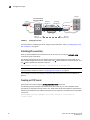
1
53-1002474-01
15 December 2011
Fabric OS FCIP
Administrator’s Guide
Supporting Fabric OS v7.0.1
®
Copyright © 2009-2011 Brocade Communications Systems, Inc. All Rights Reserved.
Brocade, the B-wing symbol, BigIron, DCX, Fabric OS, FastIron, NetIron, SAN Health, ServerIron, and TurboIron are registered
trademarks, and Brocade Assurance, Brocade NET Health, Brocade One, CloudPlex, MLX, VCS, VDX, and When the Mission Is
Critical, the Network Is Brocade are trademarks of Brocade Communications Systems, Inc., in the United States and/or in other
countries. Other brands, products, or service names mentioned are or may be trademarks or service marks of their respective
owners.
Notice: This document is for informational purposes only and does not set forth any warranty, expressed or implied, concerning
any equipment, equipment feature, or service offered or to be offered by Brocade. Brocade reserves the right to make changes to
this document at any time, without notice, and assumes no responsibility for its use. This informational document describes
features that may not be currently available. Contact a Brocade sales office for information on feature and product availability.
Export of technical data contained in this document may require an export license from the United States government.
The authors and Brocade Communications Systems, Inc. shall have no liability or responsibility to any person or entity with
respect to any loss, cost, liability, or damages arising from the information contained in this book or the computer programs that
accompany it.
The product described by this document may contain “open source” software covered by the GNU General Public License or other
open source license agreements. To find out which open source software is included in Brocade products, view the licensing
terms applicable to the open source software, and obtain a copy of the programming source code, please visit
http://www.brocade.com/support/oscd.
Brocade Communications Systems, Incorporated
Corporate and Latin American Headquarters
Brocade Communications Systems, Inc.
130 Holger Way
San Jose, CA 95134
Tel: 1-408-333-8000
Fax: 1-408-333-8101
E-mail: [email protected]
Asia-Pacific Headquarters
Brocade Communications Systems China HK, Ltd.
No. 1 Guanghua Road
Chao Yang District
Units 2718 and 2818
Beijing 100020, China
Tel: +8610 6588 8888
Fax: +8610 6588 9999
E-mail: [email protected]
European Headquarters
Brocade Communications Switzerland Sàrl
Centre Swissair
Tour B - 4ème étage
29, Route de l'Aéroport
Case Postale 105
CH-1215 Genève 15
Switzerland
Tel: +41 22 799 5640
Fax: +41 22 799 5641
E-mail: [email protected]
Asia-Pacific Headquarters
Brocade Communications Systems Co., Ltd. (Shenzhen WFOE)
Citic Plaza
No. 233 Tian He Road North
Unit 1308 – 13th Floor
Guangzhou, China
Tel: +8620 3891 2000
Fax: +8620 3891 2111
E-mail: [email protected]
Document History
Title
Publication number
Summary of changes
Date
Fabric OS FCIP Administrator’s Guide
53-1001349-01
New document.
July 2009
Fabric OS FCIP Administrator’s Guide
53-1001349-02
Various changes and
corrections.
October 2009
Fabric OS FCIP Administrator’s Guide
53-1001755-01
New document for Fabric OS January 2010
version 6.3.1.
Fabric OS FCIP Administrator’s Guide
53-1001766-01
New document for Fabric OS March 2010
version 6.4.0.
Fabric OS FCIP Administrator’s Guide
53-1002155-01
Updated document for
Fabric OS version 7.0.0.
April 2011
Fabric OS FCIP Administrator’s Guide
53-1002474-01
Updated document for
Fabric OS version 7.0.1.
December 2011
Fabric OS FCIP Administrator’s Guide
53-1002474-01
iii
iv
Fabric OS FCIP Administrator’s Guide
53-1002474-01
Contents
About This Document
In this chapter . . . . . . . . . . . . . . . . . . . . . . . . . . . . . . . . . . . . . . . . . . . . ix
How this document is organized . . . . . . . . . . . . . . . . . . . . . . . . . . . . . ix
Supported hardware and software . . . . . . . . . . . . . . . . . . . . . . . . . . . ix
What’s new in this document . . . . . . . . . . . . . . . . . . . . . . . . . . . . . . . . x
Document conventions . . . . . . . . . . . . . . . . . . . . . . . . . . . . . . . . . . . . . xi
Text formatting . . . . . . . . . . . . . . . . . . . . . . . . . . . . . . . . . . . . . . . . xi
Command syntax conventions . . . . . . . . . . . . . . . . . . . . . . . . . . . xi
Notes, cautions, and warnings . . . . . . . . . . . . . . . . . . . . . . . . . . xii
Key terms . . . . . . . . . . . . . . . . . . . . . . . . . . . . . . . . . . . . . . . . . . . xii
Notice to the reader . . . . . . . . . . . . . . . . . . . . . . . . . . . . . . . . . . . . . . xii
Additional information. . . . . . . . . . . . . . . . . . . . . . . . . . . . . . . . . . . . . xiii
Brocade resources . . . . . . . . . . . . . . . . . . . . . . . . . . . . . . . . . . . . xiii
Other industry resources . . . . . . . . . . . . . . . . . . . . . . . . . . . . . . . xiii
Getting technical help . . . . . . . . . . . . . . . . . . . . . . . . . . . . . . . . . . . . . xiii
Document feedback . . . . . . . . . . . . . . . . . . . . . . . . . . . . . . . . . . . . . . xiv
Chapter 1
FCIP Overview
In this chapter . . . . . . . . . . . . . . . . . . . . . . . . . . . . . . . . . . . . . . . . . . . . 1
FCIP platforms and supported features . . . . . . . . . . . . . . . . . . . . . . . 1
FCIP concepts . . . . . . . . . . . . . . . . . . . . . . . . . . . . . . . . . . . . . . . . . . . . 3
IP WAN network considerations . . . . . . . . . . . . . . . . . . . . . . . . . . . . . . 3
Chapter 2
FCIP on the 7800 Switch and FX8-24 Blade
In this chapter . . . . . . . . . . . . . . . . . . . . . . . . . . . . . . . . . . . . . . . . . . . . 5
7800 switch hardware overview . . . . . . . . . . . . . . . . . . . . . . . . . . . . . 6
7800 switch license options . . . . . . . . . . . . . . . . . . . . . . . . . . . . . . . . 7
VE_Ports and FCIP tunnels on the 7800 switch . . . . . . . . . . . . . 8
FCIP trunking capacity on the 7800 switch . . . . . . . . . . . . . . . . . 8
FX8-24 blade hardware overview. . . . . . . . . . . . . . . . . . . . . . . . . . . . . 8
Removing FX8-24 blades. . . . . . . . . . . . . . . . . . . . . . . . . . . . . . . 10
FX8-24 blade license options . . . . . . . . . . . . . . . . . . . . . . . . . . . . . . . 10
VE_Ports and FCIP tunnels on the FX8-24 blade. . . . . . . . . . . . 10
FCIP trunking capacity on the FX8-24 blade . . . . . . . . . . . . . . . 11
10 GbE port considerations . . . . . . . . . . . . . . . . . . . . . . . . . . . . 11
Fabric OS FCIP Administrator’s Guide
53-1002474-01
v
FCIP trunking . . . . . . . . . . . . . . . . . . . . . . . . . . . . . . . . . . . . . . . . . . . . 15
Design for redundancy and fault tolerance . . . . . . . . . . . . . . . . 16
FCIP tunnel restrictions for FCP and FICON acceleration
features . . . . . . . . . . . . . . . . . . . . . . . . . . . . . . . . . . . . . . . . . . . . 16
FCIP circuits . . . . . . . . . . . . . . . . . . . . . . . . . . . . . . . . . . . . . . . . . 16
FCIP circuit failover capabilities . . . . . . . . . . . . . . . . . . . . . . . . . 17
Failover in TI zones . . . . . . . . . . . . . . . . . . . . . . . . . . . . . . . . . . . 20
Bandwidth calculation during failover . . . . . . . . . . . . . . . . . . . . 20
Adaptive Rate Limiting . . . . . . . . . . . . . . . . . . . . . . . . . . . . . . . . . . . . 21
FSPF link cost calculation when ARL is used. . . . . . . . . . . . . . . 21
QoS SID/DID priorities over an FCIP trunk . . . . . . . . . . . . . . . . . . . . 21
QoS, DSCP, and VLANs . . . . . . . . . . . . . . . . . . . . . . . . . . . . . . . . . . . . 24
DSCP Quality of Service. . . . . . . . . . . . . . . . . . . . . . . . . . . . . . . . 24
VLANs and Layer 2 Quality of Service. . . . . . . . . . . . . . . . . . . . . 24
When both DSCP and L2CoS are used. . . . . . . . . . . . . . . . . . . . 25
DSCP and VLAN support on FCIP circuits. . . . . . . . . . . . . . . . . . 25
Managing the VLAN tag table . . . . . . . . . . . . . . . . . . . . . . . . . . . 26
Compression options . . . . . . . . . . . . . . . . . . . . . . . . . . . . . . . . . . . . . 28
IPsec implementation over FCIP tunnels. . . . . . . . . . . . . . . . . . . . . . 28
Limitations using IPsec over FCIP tunnels . . . . . . . . . . . . . . . . . 29
IPsec for the 7800 switch and FX8-24 blade. . . . . . . . . . . . . . . 29
Enabling IPsec and IKE policies . . . . . . . . . . . . . . . . . . . . . . . . . 30
Open Systems Tape Pipelining . . . . . . . . . . . . . . . . . . . . . . . . . . . . . . 30
FCIP Fastwrite and OSTP configurations . . . . . . . . . . . . . . . . . . 30
Support for IPv6 addressing. . . . . . . . . . . . . . . . . . . . . . . . . . . . . . . . 32
IPv6 with embedded IPv4 addresses . . . . . . . . . . . . . . . . . . . . . 33
Configuration preparation . . . . . . . . . . . . . . . . . . . . . . . . . . . . . . . . . 33
Configuration steps. . . . . . . . . . . . . . . . . . . . . . . . . . . . . . . . . . . . . . . 34
Setting VE_Ports to persistently disabled state . . . . . . . . . . . . . 34
Configuring VEX_Ports . . . . . . . . . . . . . . . . . . . . . . . . . . . . . . . . . 34
Enabling XISL for VE_Ports . . . . . . . . . . . . . . . . . . . . . . . . . . . . . 35
Configuring the media type for GbE ports 0 and 1 (7800
switch only). . . . . . . . . . . . . . . . . . . . . . . . . . . . . . . . . . . . . . . . . . 35
Setting the GbE port operating mode (FX8-24 blade only) . . . . 35
Configuring a GbE or XGE port IP address . . . . . . . . . . . . . . . . . 36
Configuring an IP route . . . . . . . . . . . . . . . . . . . . . . . . . . . . . . . . 37
Validating IP connectivity. . . . . . . . . . . . . . . . . . . . . . . . . . . . . . . 38
Creating an FCIP tunnel. . . . . . . . . . . . . . . . . . . . . . . . . . . . . . . . 38
Creating additional FCIP circuits . . . . . . . . . . . . . . . . . . . . . . . . 44
Verifying the FCIP tunnel configuration on the Brocade 7800
FX8-24 . . . . . . . . . . . . . . . . . . . . . . . . . . . . . . . . . . . . . . . . . . . . . 45
Enabling persistently disabled ports on the Brocade 7800
FX8-24 . . . . . . . . . . . . . . . . . . . . . . . . . . . . . . . . . . . . . . . . . . . . . 45
Creating a multicircuit tunnel (example) . . . . . . . . . . . . . . . . . . . . . . 46
Modifying an FCIP tunnel on a Brocade 7800 FX8-24 blade. . . . . . 49
Modifying an FCIP circuit on a Brocade 7800 FX8-24 blade . . . . . . 49
Deleting an IP interface on a Brocade 7800 FX8-24 blade . . . . . . . 50
vi
Fabric OS FCIP Administrator’s Guide
53-1002474-01
Deleting an IP route on a Brocade 7800 FX8-24 blade . . . . . . . . . . 50
Deleting an FCIP tunnel on a Brocade 7800 FX8-24 blade . . . . . . . 50
Deleting an FCIP circuit on a Brocade 7800 FX8-24 blade . . . . . . . 51
Virtual Fabrics and the Brocade 7800 FX8-24 blade. . . . . . . . . . . . 51
Port sharing . . . . . . . . . . . . . . . . . . . . . . . . . . . . . . . . . . . . . . . . . 51
Chapter 3
FCIP on the FR4-18i Blade
In this chapter . . . . . . . . . . . . . . . . . . . . . . . . . . . . . . . . . . . . . . . . . . . 53
FR4-18i blade . . . . . . . . . . . . . . . . . . . . . . . . . . . . . . . . . . . . . . . . . . . 54
FR4-18i blade ports. . . . . . . . . . . . . . . . . . . . . . . . . . . . . . . . . . . 55
FCIP design considerations for the FR4-18i blade . . . . . . . . . . . . . . 55
Virtual port types . . . . . . . . . . . . . . . . . . . . . . . . . . . . . . . . . . . . . 56
Compression on FCIP tunnels . . . . . . . . . . . . . . . . . . . . . . . . . . . 57
Traffic shaping . . . . . . . . . . . . . . . . . . . . . . . . . . . . . . . . . . . . . . . 57
FCIP services license . . . . . . . . . . . . . . . . . . . . . . . . . . . . . . . . . . . . . 57
QoS implementation over FCIP . . . . . . . . . . . . . . . . . . . . . . . . . . . . . 57
DSCP Quality of Service. . . . . . . . . . . . . . . . . . . . . . . . . . . . . . . . 57
L2CoS Quality of Service . . . . . . . . . . . . . . . . . . . . . . . . . . . . . . . 58
When both DSCP and L2CoS are used. . . . . . . . . . . . . . . . . . . . 58
IPsec implementation over FCIP . . . . . . . . . . . . . . . . . . . . . . . . . . . . 58
Limitations using IPsec over FCIP tunnels . . . . . . . . . . . . . . . . . 59
Configuring IPsec . . . . . . . . . . . . . . . . . . . . . . . . . . . . . . . . . . . . . 59
IPsec parameters . . . . . . . . . . . . . . . . . . . . . . . . . . . . . . . . . . . . . 60
Creating an IKE and IPsec policy . . . . . . . . . . . . . . . . . . . . . . . . 61
Displaying IKE and IPsec policy settings . . . . . . . . . . . . . . . . . . 61
Deleting an IKE and IPsec policy . . . . . . . . . . . . . . . . . . . . . . . . 61
Viewing IPsec information for an FCIP tunnel . . . . . . . . . . . . . . 62
Virtual Fabrics and FCIP . . . . . . . . . . . . . . . . . . . . . . . . . . . . . . . . . . . 62
Options for enhancing tape I/O performance . . . . . . . . . . . . . . . . . . 63
FCIP Fastwrite and OSTP configurations . . . . . . . . . . . . . . . . . . 64
Unsupported configurations for Fastwrite and OSTP . . . . . . . . 65
FCIP services configuration guidelines . . . . . . . . . . . . . . . . . . . . . . . 66
Setting persistently disabled ports . . . . . . . . . . . . . . . . . . . . . . . . . . 67
Configuring VEX_Ports . . . . . . . . . . . . . . . . . . . . . . . . . . . . . . . . . . . . 67
Creating IP interfaces and routes . . . . . . . . . . . . . . . . . . . . . . . . . . . 67
Creating an FCIP tunnel . . . . . . . . . . . . . . . . . . . . . . . . . . . . . . . . . . . 69
Verifying the FCIP tunnel configuration on the Brocade FR4-18i . . 69
Enabling persistently disabled ports on the Brocade 7500 FR4-18i70
Managing FCIP tunnels. . . . . . . . . . . . . . . . . . . . . . . . . . . . . . . . . . . . 70
Modifying and deleting QoS settings . . . . . . . . . . . . . . . . . . . . . 71
Deleting an FCIP tunnel on a Brocade 7500 FR4-18i. . . . . . . . 71
Deleting an IP route on a Brocade 7500 FR4-18i . . . . . . . . . . . 72
Deleting an IP interface on a Brocade 7500 FR4-18i. . . . . . . . 72
Fabric OS FCIP Administrator’s Guide
53-1002474-01
vii
Managing the VLAN tag table. . . . . . . . . . . . . . . . . . . . . . . . . . . . . . . 72
Chapter 4
FCIP Management and Troubleshooting
In this chapter . . . . . . . . . . . . . . . . . . . . . . . . . . . . . . . . . . . . . . . . . . . 73
Inband management . . . . . . . . . . . . . . . . . . . . . . . . . . . . . . . . . . . . . 73
IP routing . . . . . . . . . . . . . . . . . . . . . . . . . . . . . . . . . . . . . . . . . . . 74
Configuring IP addresses and routes . . . . . . . . . . . . . . . . . . . . . 74
VLAN tagging support . . . . . . . . . . . . . . . . . . . . . . . . . . . . . . . . . 78
IP forwarding support . . . . . . . . . . . . . . . . . . . . . . . . . . . . . . . . . 78
WAN performance analysis tools . . . . . . . . . . . . . . . . . . . . . . . . . . . . 80
The tperf option . . . . . . . . . . . . . . . . . . . . . . . . . . . . . . . . . . . . . . 80
The ipperf option . . . . . . . . . . . . . . . . . . . . . . . . . . . . . . . . . . . . . 82
Ipperf performance statistics . . . . . . . . . . . . . . . . . . . . . . . . . . . 83
Starting an ipperf session . . . . . . . . . . . . . . . . . . . . . . . . . . . . . . 83
Ipperf options . . . . . . . . . . . . . . . . . . . . . . . . . . . . . . . . . . . . . . . . 84
Using ping to test a connection. . . . . . . . . . . . . . . . . . . . . . . . . . 84
Using traceroute. . . . . . . . . . . . . . . . . . . . . . . . . . . . . . . . . . . . . . 84
Portshow command usage . . . . . . . . . . . . . . . . . . . . . . . . . . . . . . . . . 85
Displaying IP interfaces . . . . . . . . . . . . . . . . . . . . . . . . . . . . . . . . 85
Displaying IP routes . . . . . . . . . . . . . . . . . . . . . . . . . . . . . . . . . . . 85
Displaying FCIP tunnel information. . . . . . . . . . . . . . . . . . . . . . . 85
Displaying IP addresses. . . . . . . . . . . . . . . . . . . . . . . . . . . . . . . . 85
Displaying performance statistics. . . . . . . . . . . . . . . . . . . . . . . . 86
Displaying FCIP tunnel information (7800 switch and
FX8-24 blade). . . . . . . . . . . . . . . . . . . . . . . . . . . . . . . . . . . . . . . . 86
Displaying an FCIP tunnel with FCIP circuit information
(7800 switch and FX8-24 blade) . . . . . . . . . . . . . . . . . . . . . . . . 86
Displaying FCIP tunnel performance (7800 switch and
FX8-24 blade). . . . . . . . . . . . . . . . . . . . . . . . . . . . . . . . . . . . . . . . 87
Displaying FCIP tunnel TCP connections (7800 switch
and FX8-24 blade) . . . . . . . . . . . . . . . . . . . . . . . . . . . . . . . . . . . . 87
Displaying FCIP circuits (7800 switch and FX8-24 blade) . . . . 87
Displaying a single circuit . . . . . . . . . . . . . . . . . . . . . . . . . . . . . . 87
Displaying FCIP circuit performance (7800 switch and
FX8-24 blade). . . . . . . . . . . . . . . . . . . . . . . . . . . . . . . . . . . . . . . . 87
Displaying QoS prioritization for a circuit . . . . . . . . . . . . . . . . . . 88
Displaying FCIP tunnel information (FR4-18i blade) . . . . . . . . . 88
FCIP tunnel issues. . . . . . . . . . . . . . . . . . . . . . . . . . . . . . . . . . . . . . . . 88
FCIP links . . . . . . . . . . . . . . . . . . . . . . . . . . . . . . . . . . . . . . . . . . . . . . . 90
Gathering additional information . . . . . . . . . . . . . . . . . . . . . . . . 90
FTRACE concepts . . . . . . . . . . . . . . . . . . . . . . . . . . . . . . . . . . . . . . . . 91
Index
viii
Fabric OS FCIP Administrator’s Guide
53-1002474-01
About This Document
In this chapter
• How this document is organized . . . . . . . . . . . . . . . . . . . . . . . . . . . . . . . . . . . ix
• Supported hardware and software. . . . . . . . . . . . . . . . . . . . . . . . . . . . . . . . . . ix
• What’s new in this document . . . . . . . . . . . . . . . . . . . . . . . . . . . . . . . . . . . . . . x
• Document conventions . . . . . . . . . . . . . . . . . . . . . . . . . . . . . . . . . . . . . . . . . . . xi
• Notice to the reader . . . . . . . . . . . . . . . . . . . . . . . . . . . . . . . . . . . . . . . . . . . . xii
• Additional information . . . . . . . . . . . . . . . . . . . . . . . . . . . . . . . . . . . . . . . . . . . xiii
• Getting technical help . . . . . . . . . . . . . . . . . . . . . . . . . . . . . . . . . . . . . . . . . . . xiii
• Document feedback . . . . . . . . . . . . . . . . . . . . . . . . . . . . . . . . . . . . . . . . . . . . xiv
How this document is organized
.
This document is organized to help you find the information that you want as quickly and easily as
possible. It contains the following components:
• Chapter 1, “FCIP Overview” describes FCIP concepts and features.
• Chapter 2, “FCIP on the 7800 Switch and FX8-24 Blade” describes FCIP tunnel and trunking
configuration options for the 7800 switch and FX8-24 blade.
• Chapter 3, “FCIP on the FR4-18i Blade” describes FCIP tunnel configuration options for the
FR4-18i blade.
• Chapter 4, “FCIP Management and Troubleshooting” describes FCIP management and
troubleshooting operations.
Supported hardware and software
The following hardware platforms support FCIP as described in this manual:
• Brocade DCX, DCX 8510-8, DCX-4S, and DCX 8510-4 with one or more FX8-24 blades
• Brocade 7800 switch
• Brocade DCX and DCX-4S with one or more FR4-18i blades
NOTE
FR4-18i blades are not supported on the16 Gbps DCX 8510-8 and DCX 8510-4 models.
Fabric OS FCIP Administrator’s Guide
53-1002474-01
ix
What’s new in this document
Major new additions or deletions in this document support the following:
• Preface. Added location of serial number label for the Brocade 6505 switch.
• Chapter 1
- Added support for printer emulation in Table 1, “FCIP capabilities by platform,” under the
FICON extension row and referenced statement that this is not supported on FR4-18i
blades.
-
Added note under “FCIP platforms and supported features” that FCIP connections are not
supported between the 7800 switch or FX8-24 blades and previous generation Brocade
7500 switches or FR4-18i blades.
• Chapter 2
- Under “7800 switch hardware overview,” added the following notes:
• Copper ports do not support auto-sense functions.
• With copper media, auto-negotiation must be enabled on the other end of the port
connection. 1 Gbps is the only negotiated speed.
-
Under 7800 switch license options” and “FX8-24 blade license options,” added FICON
printer emulation to the list of features enabled by the Advanced FICON Acceleration
License. Also added printer and other emulation features to the Advanced FICON
Acceleration License row of Table 2, “7800 FCIP feature licenses” and Table 3, “FX8-24
blade license options.”
-
Under “VE_Ports and FCIP tunnels on the 7800 switch” and “VE_Ports and FCIP tunnels
on the FX8-24 blade” added the following note:
-
VE_Ports or VEX_Ports cannot connect to the same domain at the same time as Fibre
Channel E_Ports or EX_Ports.
-
Under “VE_Ports and FCIP tunnels on the 7800 switch” and “VE_Ports and FCIP tunnels
on the FX8-24 blade” a note was added concerning VE_Ports.
-
Under “FCIP tunnel restrictions for FCP and FICON acceleration features,” added
restrictions about FCIP tunnels not supporting DPS and that both ends of the FICON
emulating tunnel must run Fabric OS v7.0 or later if one end of tunnel runs v7.0 or later.
-
Under “FCIP circuit failover capabilities, added “Failover in TI zones” section.
-
Added timeout value information under the “keep-alive timeout” option.
-
Added notes under the “Setting the GbE port operating mode (FX8-24 blade only)” section.
Under “Limitations using IPsec over FCIP tunnels,” added limitation that IPsec is not
supported on VE group 12-21 on FX8-24 blades and that to enable IPsec with Fabric OS
v7.0 and later, both ends of the tunnel must use v7.0 and later.
Under “Creating Additional FCIP circuits,” added note about adding additional circuits to
an active tunnel when multiple FCIP tunnels are present.
• Chapter 4
- Under “Inband management,” added that the following functions are not supported by the
inband management interface:
• Downloading firmware
• IPv6 addressing
x
Fabric OS FCIP Administrator’s Guide
53-1002474-01
Document conventions
This section describes text formatting conventions and important notice formats used in this
document.
Text formatting
The narrative-text formatting conventions that are used are as follows:
bold text
Identifies command names
Identifies the names of user-manipulated GUI elements
Identifies keywords and operands
Identifies text to enter at the GUI or CLI
italic text
Provides emphasis
Identifies variables
Identifies paths and Internet addresses
Identifies document titles
code text
Identifies CLI output
Identifies command syntax examples
For readability, command names in the narrative portions of this guide are presented in mixed
lettercase: for example, switchShow. In actual examples, command lettercase is often all
lowercase. Otherwise, this manual specifically notes those cases in which a command is
case-sensitive.
Command syntax conventions
Command syntax in this manual follows these conventions:
command
Commands are printed in bold.
--option, option
Command options are printed in bold.
-argument, arg
Arguments.
[]
Optional element.
variable
Variables are printed in italics. In the help pages, variables are underlined or
enclosed in angled brackets < >.
...
Repeat the previous element, for example “member[;member...]”
value
Fixed values following arguments are printed in plain font. For example,
--show WWN
|
Boolean. Elements are exclusive. Example: --show -mode egress | ingress
\
Backslash. Indicates that the line continues through the line break. For
command line input, type the entire line without the backslash.
Fabric OS FCIP Administrator’s Guide
53-1002474-01
xi
Notes, cautions, and warnings
The following notices and statements are used in this manual. They are listed below in order of
increasing severity of potential hazards.
NOTE
A note provides a tip, guidance, or advice, emphasizes important information, or provides a
reference to related information.
ATTENTION
An Attention statement indicates potential damage to hardware or data.
CAUTION
A Caution statement alerts you to situations that can cause damage to hardware, firmware,
software, or data.
DANGER
A Danger statement indicates conditions or situations that can be potentially lethal or extremely
hazardous to you. Safety labels are also attached directly to products to warn of these conditions
or situations.
Key terms
For definitions specific to Brocade and Fibre Channel, see the technical glossaries on MyBrocade.
See “Brocade resources” on page xiii for instructions on accessing MyBrocade.
For definitions of SAN-specific terms, visit the Storage Networking Industry Association online
dictionary at:
http://www.snia.org/education/dictionary
Notice to the reader
This document may contain references to the trademarks of the following corporations. These
trademarks are the properties of their respective companies and corporations.
These references are made for informational purposes only.
xii
Corporation
Referenced Trademarks and Products
Microsoft Corporation
Windows, Windows NT, Internet Explorer
Fabric OS FCIP Administrator’s Guide
53-1002474-01
Additional information
This section lists additional Brocade and industry-specific documentation that you might find
helpful.
Brocade resources
To get up-to-the-minute information, go to http://my.brocade.com and register at no cost for a user
ID and password.
For additional Brocade documentation, visit the Brocade SAN Info Center and click the Resource
Library location:
http://www.brocade.com
Release notes are available on the MyBrocade website and are also bundled with the Fabric OS
firmware.
Other industry resources
• White papers, online demos, and data sheets are available through the Brocade website at
http://www.brocade.com/products-solutions/products/index.page.
• Best practice guides, white papers, data sheets, and other documentation is available through
the Brocade Partner website.
For additional resource information, visit the Technical Committee T11 website. This website
provides interface standards for high-performance and mass storage applications for Fibre
Channel, storage management, and other applications:
http://www.t11.org
For information about the Fibre Channel industry, visit the Fibre Channel Industry Association
website:
http://www.fibrechannel.org
Getting technical help
Contact your switch support supplier for hardware, firmware, and software support, including
product repairs and part ordering. To expedite your call, have the following information available:
1. General Information
•
•
•
•
•
Switch model
Switch operating system version
Error numbers and messages received
supportSave command output
Detailed description of the problem, including the switch or fabric behavior immediately
following the problem, and specific questions
• Description of any troubleshooting steps already performed and the results
Fabric OS FCIP Administrator’s Guide
53-1002474-01
xiii
• Serial console and Telnet session logs
• syslog message logs
2. Switch Serial Number
The switch serial number and corresponding bar code are provided on the serial number label,
as illustrated below:
*FT00X0054E9*
FT00X0054E9
The serial number label is located as follows:
• Brocade 300, 5100, 5300, 7800, 8000, VA-40FC, 6505, 6510, and Brocade Encryption
Switch—On the switch ID pull-out tab located inside the chassis on the port side on the left
• Brocade 5410, M5424, 5450, 5460, 5470, 5480—Serial number label attached to the
module
• DCX 8510-8 and DCX—On the port side of the chassis, on the lower right side and directly
above the cable management comb.
• DCX 8510-4 and DCX-4S—On the nonport side of the chassis, on the lower left side.
3. World Wide Name (WWN)
4. Use the licenseIdShow command to display the switch WWN.
If you cannot use the licenseIdShow command because the switch is inoperable, you can get
the WWN from the same place as the serial number, except for the Brocade DCX and DCX-4S.
For the Brocade DCX and DCX-4S, access the numbers on the WWN cards by removing the
Brocade logo plate at the top of the non-port side of the chassis.
Document feedback
Quality is our first concern at Brocade and we have made every effort to ensure the accuracy and
completeness of this document. However, if you find an error or an omission, or you think that a
topic needs further development, we want to hear from you. Forward your feedback to:
[email protected]
Provide the title and version number of the document and as much detail as possible about your
comment, including the topic heading and page number and your suggestions for improvement.
xiv
Fabric OS FCIP Administrator’s Guide
53-1002474-01
Chapter
1
FCIP Overview
In this chapter
• FCIP platforms and supported features. . . . . . . . . . . . . . . . . . . . . . . . . . . . . . 1
• FCIP concepts . . . . . . . . . . . . . . . . . . . . . . . . . . . . . . . . . . . . . . . . . . . . . . . . . . 3
• IP WAN network considerations . . . . . . . . . . . . . . . . . . . . . . . . . . . . . . . . . . . . 3
FCIP platforms and supported features
There are three Brocade platforms that support FCIP:
• The Brocade 7800 switch
• The Brocade FX8-24 blade (DCX, DCX-4S, DCX 8510-8, and DCX 8510-4 chassis)
• The Brocade FR4-18i blade (DCX, DCX-4S chassis)
NOTE
FCIP connections are not supported between 7800 switch or FX8-24 blades and previous
generation Brocade 7500 switches or FR4-18i blades.
Note the following about hardware support:
• The FR4-18i blade is not supported on the 16 Gbps DCX 8510-8, and DCX 8510-4 chassis.
• The FX8-24 and FR4-18i blades are not supported concurrently in the same chassis.
• There are differences in platform capabilities. For example, the FR4-18i blade cannot support
FCIP trunking.
Table 1 summarizes FCIP capabilities per platform.
TABLE 1
FCIP capabilities by platform
Capabilities
7800 switch
FX8-24 blade
FR4-18i blade
FCIP trunking
Yes
Yes
No
Adaptive Rate Limiting
Yes
Yes
No
10GbE ports
No
Yes
No
FC ports up to 8 Gbps
Yes (1, 2, 4, 8
Gbps)
Yes (1, 2, 4, 8
Gbps)
No (1, 2, 4 Gbps)
Compression
Yes
LZ and Deflate
Yes
LZ and Deflate
Yes
LZ only
Fabric OS FCIP Administrator’s Guide
53-1002474-01
1
1
FCIP platforms and supported features
TABLE 1
FCIP capabilities by platform (Continued)
Capabilities
7800 switch
FX8-24 blade
FR4-18i blade
Protocol acceleration
• FCIP Fastwrite
• Open Systems Tape
Pipelining
- OSTP read
- OSTP write
Yes
Yes
Yes
QoS
•
•
Marking DSCP
Yes
Yes
Yes
Marking 802.1P - VLAN
tagging
Yes
Yes
Yes
•
Enforcement 802.1P - VLAN
tagging
Yes
Yes
No
FICON extension
FICON emulation
IBM z/OS Global Mirror
(formerly eXtended Remote
Copy or XRC) acceleration
• Tape read acceleration
• Tape write acceleration
• Teradata emulation1
• Printer emulation1
Yes
Yes
Yes
•
IPsec
AES encryption algorithm
Yes
Transport mode
Yes
Transport mode
Yes
Tunnel mode
VEX_Ports
Yes
Yes
Yes
•
•
2
2
Support for third-party WAN
optimization hardware
No
No
No2
IPv6 addresses for FCIP
tunnels3
Yes
Yes
Yes
Support for jumbo frames
No2
MTU of 1500 is
maximum
No2
MTU of 1500 is
maximum
Yes
1.
This emulation is not supported on the FR4-18i blade.
2.
Not supported in Fabric OS version v7.0 and later.
3.
IPv6 addressing is not supported in conjunction with IPsec in Fabric OS version v7.0.1.
Fabric OS FCIP Administrator’s Guide
53-1002474-01
FCIP concepts
1
FCIP concepts
Fibre Channel over IP (FCIP) enables you to use existing IP wide area network (WAN) infrastructure
to connect Fibre Channel SANs. FCIP supports applications such as remote data replication (RDR),
centralized SAN backup, and data migration over very long distances that are impractical or very
costly using native Fibre Channel connections. FCIP tunnels are used to pass Fibre Channel I/O
through an IP network. FCIP tunnels are built on a physical connection between two peer switches
or blades. Fibre Channel frames enter FCIP through virtual E_Ports (VE_Ports or VEX_Ports) and are
encapsulated and passed to Transmission Control Protocol (TCP) layer connections. The TCP
connections ensure in-order delivery of FC frames and lossless transmission. The Fibre Channel
fabric and all Fibre Channel targets and initiators are unaware of the presence of the IP network.
Figure 1 shows the relationship of FC and TCP/IP layers, and the general concept of FCIP tunneling.
FC-IP
FC-IP
FC-2
TCP
TCP
FC-2
FC-1
IP
IP
FC-1
FC-0
LINK
LINK
FC-0
PHY
WAN
To Fibre Channel
PHY
To Fibre Channel
FCIP Tunnel
FIGURE 1
FCIP tunnel concept and TCP/IP layers
IP WAN network considerations
Because FCIP uses TCP connections over an existing wide area network, consult with the WAN
carrier and IP network administrator to ensure that the network hardware and software equipment
operating in the data path can properly support the TCP connections. Keep the following
considerations in mind:
• Routers and firewalls that are in the data path must be configured to pass FCIP traffic (TCP
port 3225) and IPsec traffic, if IPsec is used (UDP port 500). TCP port 3226 must be
configured for the FR4-18i only.
• To enable recovery from a WAN failure or outage, be sure that diverse, redundant network
paths are available across the WAN.
• Be sure the underlying WAN infrastructure is capable of supporting the redundancy and
performance expected in your implementation.
Fabric OS FCIP Administrator’s Guide
53-1002474-01
3
1
4
IP WAN network considerations
Fabric OS FCIP Administrator’s Guide
53-1002474-01
Chapter
FCIP on the 7800 Switch and FX8-24 Blade
2
In this chapter
• 7800 switch hardware overview. . . . . . . . . . . . . . . . . . . . . . . . . . . . . . . . . . . . 6
• 7800 switch license options. . . . . . . . . . . . . . . . . . . . . . . . . . . . . . . . . . . . . . . 7
• FX8-24 blade hardware overview . . . . . . . . . . . . . . . . . . . . . . . . . . . . . . . . . . . 8
• FX8-24 blade license options . . . . . . . . . . . . . . . . . . . . . . . . . . . . . . . . . . . . . 10
• FCIP trunking . . . . . . . . . . . . . . . . . . . . . . . . . . . . . . . . . . . . . . . . . . . . . . . . . . 15
• Adaptive Rate Limiting . . . . . . . . . . . . . . . . . . . . . . . . . . . . . . . . . . . . . . . . . . 21
• QoS SID/DID priorities over an FCIP trunk. . . . . . . . . . . . . . . . . . . . . . . . . . . 21
• QoS, DSCP, and VLANs . . . . . . . . . . . . . . . . . . . . . . . . . . . . . . . . . . . . . . . . . . 24
• Compression options. . . . . . . . . . . . . . . . . . . . . . . . . . . . . . . . . . . . . . . . . . . . 28
• IPsec implementation over FCIP tunnels . . . . . . . . . . . . . . . . . . . . . . . . . . . . 28
• Open Systems Tape Pipelining . . . . . . . . . . . . . . . . . . . . . . . . . . . . . . . . . . . . 30
• Support for IPv6 addressing . . . . . . . . . . . . . . . . . . . . . . . . . . . . . . . . . . . . . . 32
• Configuration preparation. . . . . . . . . . . . . . . . . . . . . . . . . . . . . . . . . . . . . . . . 33
• Configuration steps . . . . . . . . . . . . . . . . . . . . . . . . . . . . . . . . . . . . . . . . . . . . . 34
• Creating a multicircuit tunnel (example) . . . . . . . . . . . . . . . . . . . . . . . . . . . . 46
• Modifying an FCIP tunnel on a Brocade 7800 FX8-24 blade . . . . . . . . . . . . 49
• Modifying an FCIP circuit on a Brocade 7800 FX8-24 blade . . . . . . . . . . . . 49
• Deleting an IP interface on a Brocade 7800 FX8-24 blade . . . . . . . . . . . . . 50
• Deleting an IP route on a Brocade 7800 FX8-24 blade . . . . . . . . . . . . . . . . 50
• Deleting an FCIP tunnel on a Brocade 7800 FX8-24 blade . . . . . . . . . . . . . 50
• Deleting an FCIP circuit on a Brocade 7800 FX8-24 blade . . . . . . . . . . . . . 51
• Virtual Fabrics and the Brocade 7800 FX8-24 blade . . . . . . . . . . . . . . . . . . 51
Fabric OS FCIP Administrator’s Guide
53-1002474-01
5
2
7800 switch hardware overview
7800 switch hardware overview
Figure 2 shows the FC ports and GbE ports on the 7800 switch. There are 16 FC ports, numbered
0 through 15. The FC ports can operate at 1, 2, 4, or 8 Gbps. There are 6 GbE ports, numbered 0
through 5. Ports 0 and 1 are available as either RJ-45 ports or small form factor pluggable (SFP)
transceiver ports. Only six total GbE ports can be used. The 6 GbE ports together can provide up to
6 Gbps total bandwidth.
1
3
2
4
1
FC ports 0 through 3
3
Copper GbE ports 0 and 1 (these ports are
RJ-45 copper alternatives for GbE ports 0
and 1.)
2
FC ports 4 through 15
4
GbE ports 0 though 5
FIGURE 2
7800 switch FC and GbE ports
The 7800 switch comes in two models:
• The 7800 4/2 base model uses FC ports 0 through 3, and GbE ports 0 and 1. The GbE ports
can be either copper or optical. The RJ-45 copper ports are the default ports. Consider the
following when using these ports:
-
Copper ports do not support auto-sense functions.
With copper media, auto-negotiation must be enabled on the other end of the port
connection. 1 Gbps is the only negotiated speed.
• The 7800 16/6 uses FC ports 0 through 15, and GbE ports 0 through 5. The 7800 upgrade
license is required. A 7800 upgrade license can be purchased for a 7800 4/2, which enables
12 more Fibre Channel ports for a total of 16, and enables the use of 4 more optical GbE ports
for a total of 6.
6
Fabric OS FCIP Administrator’s Guide
53-1002474-01
7800 switch license options
2
7800 switch license options
Some of the capabilities of the Brocade 7800 switch require the following feature license, as
described in Table 2.
• The Advanced FICON Acceleration License enables all FICON emulation features:
- FICON Tape Read Pipelining
- FICON Tape Write Pipelining
- FICON IBM z/OS Global Mirror (formerly eXtended Remote Copy or XRC) Emulation
- FICON Teradata Emulation
- FICON Printer Emulation
• The Integrated Routing (IR) License is required to configure VEX_Ports to support Fibre
Channel Routing (FCR).
TABLE 2
7800 FCIP feature licenses
Feature
Purpose
License (licenseShow output)
7800 upgrade
Enables full hardware
capabilities, full FCIP tunnel
capabilities, support of advanced
capabilities such as open
systems tape pipelining (OSTP),
FICON CUP support, and
separately licensed advanced
FICON acceleration feature. 1
7800 Upgrade license
Advanced FICON acceleration
Enables accelerated tape
read/write and IBM z/OS Global
Mirror, Teradata, and printer
emulation features in FICON
environments.
Advanced FICON Acceleration (FTR_AFA)
license
Integrated routing (IR)
Required to configure VEX_Ports
to support Fibre Channel Routing
(FCR).
Integrated Routing license
Advanced Extension License
Required for multiple-circuit
tunnels, FCIP trunking, Adaptive
Rate Limiting (ARL), and other
FCIP features.
Advanced Extension (FTR_AE) license
1.
Reboot of 7800 is required after activating the 7800 upgrade license.
Refer to the chapter on administering licensing in the Brocade Fabric OS Administrator’s Guide for
complete information about licensing requirements.
Fabric OS FCIP Administrator’s Guide
53-1002474-01
7
2
FX8-24 blade hardware overview
VE_Ports and FCIP tunnels on the 7800 switch
A 7800 switch can support eight VE_Ports. VE_Ports are numbered from 16 through 23. Each FCIP
tunnel is identified with a VE_Port number. Up to eight FCIP tunnels can be created. The 7800
switch supports VEX_Ports to avoid the need to merge fabrics.
Consider the following when using tunnels and VE_Ports:
• On a 7800, the total bandwidth limit is 6 Gbps for VE_Ports.
• As a best practice, Fibre Channel traffic through a VE_Port tunnel should not exceed
recommended oversubscription guidelines. General guidelines include 2-to-1 oversubscription
without compression (for example, 1 Gbps over a 500 Mbps tunnel) and 4-to-1
oversubscription with compression.
• VE_Ports or VEX_Ports cannot connect to the same domain at the same time as Fibre Channel
E_Ports or EX_Ports.
FCIP trunking capacity on the 7800 switch
FCIP trunks are built by creating a set of FCIP circuits. FCIP circuits create multiple source and
destination addresses for routing traffic over a WAN, providing load leveling and failover
capabilities over an FCIP tunnel. When the 7800 upgrade license and Advanced Extension License
are activated, the FCIP trunking capacity is as follows:
•
•
•
•
The maximum trunk capacity is 6 Gbps.
You can define up to eight IP addresses for a GbE port.
There is a hard limit of four FCIP circuits per GbE port, each requiring a unique IP address.
Up up to six FCIP circuits can be defined per FCIP tunnel. These circuits can be spread out over
any GbE ports.
• A single FCIP circuit cannot exceed 1 Gbps capacity.
FX8-24 blade hardware overview
Figure 3 on page 9 shows the FC ports, GbE ports, and 10GbE ports on the FX8-24 blade. There
are 12 FC ports, numbered 0 through 11. The FC ports can operate at 1, 2, 4, or 8 Gbps. There are
10 GbE ports, numbered 0 through 9. Ports xge0 and xge1 are 10GbE ports.
The FX8-24 blade allows a maximum of 20 Gbps of bandwidth for tunnel connections, and can
operate in one of three different modes:
• 1 Gbps mode - You can use all ten GbE ports (0 through 9). Both XGE ports are disabled.
• 10 Gbps mode - You can use the xge0 and xge1 ports.
• Dual mode - You can use GbE ports 0 through 9, and port xge0.
The FX8-24 blade can be deployed in either a DCX, DCX-4S, DCX 8510-8, or DCX 8510-4 chassis.
8
Fabric OS FCIP Administrator’s Guide
53-1002474-01
FX8-24 blade hardware overview
6
2
7
2
3
1
5
4
1
10GbE ports (Labeled xge0 and xge1
on the sticker.)
5
FC ports 0 through 5
2
GbE ports 0 through 3
6
Power LED
3
GbE ports 4 through 9
7
Status LED
4
FC ports 6 through 11
FIGURE 3
Fabric OS FCIP Administrator’s Guide
53-1002474-01
FX8-24 blade FC and GbE ports
9
2
FX8-24 blade license options
Removing FX8-24 blades
ATTENTION
If you are permanently removing a blade from a DCX, DCX-4S, DCX 8510-8, or DCX 8510-4 chassis
to relocate to another slot in the chassis or you are removing the blade from the chassis entirely, you
must follow these procedures before removing the blade.
• Remove all FCIP configuration settings for the blade. If there are residual configuration
settings, they may cause issues with future configurations and upgrades.
• Delete the IP addresses assigned to the original slot using the portcfg ipif delete command. If
this is not done, you must return the FX8-24 blade to the original slot and delete the IP
addresses.
FX8-24 blade license options
Some of the capabilities of the FX8-24 blade require the slot-based feature licenses shown in
Table 3. Use the licenseshow command to display license keys and licenses currently installed.
TABLE 3
FX8-24 FCIP feature licenses
Feature
Purpose
License (licenseShow output)
10GbE support
Allows 10 Gbps operation on 10
GbE ports.
10 Gigabit FCIP/Fibre Channel (FTR_10G)
license
Advanced FICON acceleration
Enables accelerated tape
read/write and IBM z/OS Global
Mirror, Teradata, and printer
emulation features in FICON
environments.
Advanced FICON Acceleration (FTR_AFA)
license
Integrated routing (IR)
Required to configure VEX_Ports
to support Fibre Channel Routing
(FCR).
Integrated Routing license
Advanced Extension License
Required for multiple-circuit
tunnels, FCIP trunking, Adaptive
Rate Limiting (ARL), and other
FCIP features.
Advanced Extension (FTR_AE) license
Refer to the administering licensing chapter in the Fabric OS Administrator’s Guide for complete
information about licensing requirements.
VE_Ports and FCIP tunnels on the FX8-24 blade
An FX8-24 blade can support 20 VE_Ports, and therefore 20 FCIP tunnels.There are two VE_Port
groups, numbered 12 through 21 and 22 through 31. Each FCIP tunnel is associated with a specific
VE_Port.
VE_Ports do not have to be associated with a particular GbE port on FX8-24 blades and the 7800
switch. VE_Port versus GbE port usage depends on the blade operating mode as follows:
• 1 Gbps mode: VE_Ports 12 through 21 use GbE ports 0 through 9
• Dual mode: VE_Ports 12 through 21 use GbE ports 0 through 9; VE_Ports 22 through 31 use
xge0
10
Fabric OS FCIP Administrator’s Guide
53-1002474-01
FX8-24 blade license options
2
• 10 Gbps mode: VE_Ports 12 through 21 use xge1; VE_Ports 22 through 31 use xge0
NOTE
In 10 Gbps mode, you can also configure VE_Ports 12 through 21 to use port xge0 as a
crossport and VE_Ports 22 through 31 to use port xge1 as a crossport. Refer to “Crossports”
on page 13 for more information.
Considerations for using VE_Ports and FCIP tunnels
Consider the following when using VE_Ports and tunnels:
• Total bandwidth cannot exceed 20 Gbps for VE_Ports.
• As a best practice, Fibre Channel traffic through a VE_Port tunnel should not exceed
recommended oversubscription guidelines. General guidelines include 2-to-1 oversubscription
without compression (for example, 1 Gbps over a 500 Mbps tunnel) and 4-to-1
oversubscription with compression.
• VE_Ports or VEX_Ports cannot connect to the same domain at the same time as Fibre Channel
E_Ports or EX_Ports.
FCIP trunking capacity on the FX8-24 blade
FCIP trunking provides load leveling and failover capabilities through the use of multiple FCIP
circuits:
• FCIP tunnels using 1 GbE or 10 GbE ports can have up to ten FCIP circuits spread across any
GbE ports.
• You can define up to eight IP addresses (0 through 8 minus the default IPv6 “link-local”
address) for a GbE port.
• Up to four FCIP circuits can be configured per 1 GbE port, each requiring a unique IP address.
• Up to ten FCIP circuits can be configured per 10 GbE port, each requiring a unique IP address.
• A single circuit between 1 GbE ports cannot exceed 1 Gbps capacity.
10 GbE port considerations
Enhanced 10GbE port operation is different than 1 GbE port operation and requires special
considerations when configuring circuits, tunnels, failover operations, and bandwidth.
Multigigabit circuits
For each 10 GbE port, you can configure multigigabit circuits. For example, a single 10 Gbps circuit
or two 5 Gbps circuits can be configured per port. A limit of 10 FCIP circuits can be configured on a
single port. The blade at each end of the tunnel must be running Fabric OS v7.0 and later if the
committed rate for circuits exceeds 1 Gbps.The maximum committed rate for a circuit between 10
GbE ports is 10 Gbps.
Fabric OS FCIP Administrator’s Guide
53-1002474-01
11
2
FX8-24 blade license options
Bandwidth allocation and restrictions
You cannot configure more than 10 Gbps of dedicated bandwidth on a 10GbE port. This includes
both primary and secondary circuits. Following are two examples to clarify these requirements.
NOTE
In the following examples, configuring VE_Port 12 on xge0 is a crossport configuration. For more
information on crossports, refer to “Configuring crossports” on page 13.
NOTE
The terms “XGE port” and “GbE port” may be used interchangeably in this document.
• VE_Port 12 has two 10 Gbps circuits. Circuit 0 has a metric of 0 on xge1 and circuit 1 has a
metric 1 on xge0. With this configuration, no other tunnels or circuits would be allowed on this
blade because both XGE ports have 10 Gbps of configured bandwidth.
• VE_Port 12 has two 10 Gbps circuits. Circuit 0 has a metric of 0 on xge1, and circuit 1 has a
metric of 1 on xge0. In this case, the configuration is allowed, but you could not create
additional circuits for either VE port group. For the VE_Port 12-21 port group, VE_Port 12 is
consuming 10 Gbps of back end port bandwidth, so additional circuits from another tunnel
could not be created. For the VE_Port 22-31 group, the bandwidth would exceed either the
front end port bandwidth or the crossport bandwidth. Again VE_Port 12 circuit 1 is consuming
10 Gbps of crossport bandwidth and 10 Gbps of front end port bandwidth for xge0, so you
cannot create additional circuits for VE_Port 22-31 group.
Note that there can only be a maximum of 10 Gbps defined over the crossport configuration.
Therefore, in the preceding example, since VE_Port 12 is configured with a single 10 Gbps
circuit over xge0 (which would be the crossport for VE_Port 12-21 group), there can be no other
crossport configurations. You could not configure a crossport for VE_Port 22-31 port group
because VE_Port 12 is using all 10 Gbps bandwidth for xge0. This would also restrict you from
configuring any circuits for VE_Ports 22-31 at all. Therefore, consuming the crossport
bandwidth for primary metric 0 circuits is not recommended. Refer to “Crossport bandwidth
allocation” on page 15 for more information.
Back-end bandwidth
Back-end port bandwidth allocation is calculated as follows:
• Back-end bandwidths are always rounded up to the nearest 1 Gbps. For example, 1.5 Gbps
actually consumes 2 Gbps of back-end bandwidth.
• Each VE_Port group is allocated 10 Gbps of back-end bandwidth (10 Gbps for the VE_Port
12-21 group and 10 Gbps for the VE_Port 22-31 group).
• The total back-end port bandwidth allocation is calculated by adding up the consumed
bandwidth for each FCIP tunnel in the VE_Port group.
• The consumed bandwidth for a given FCIP tunnel is calculated by adding the maximum
committed rates (rounded to the nearest 1 Gbps) for all metric 0 circuits, adding up the
maximum committed rates (also rounded to the nearest 1 Gbps) for all metric 1 circuits, then
taking the greater of the two values.
12
Fabric OS FCIP Administrator’s Guide
53-1002474-01
FX8-24 blade license options
2
Front-end bandwidth
Front-end port bandwidth allocation is calculated as follows:
• Each 10 GbE port is allocated 10 Gbps of front-end bandwidth. The total front-end port
bandwidth allocation cannot exceed 10 Gbps per 10 GbE port.
• The total front-end port bandwidth allocation is calculated by adding up the consumed
bandwidth for each FCIP tunnel using that XGE port.
• The consumed bandwidth for a given FCIP tunnel is calculated by adding up the maximum
committed rates (not rounded) for all metric 0 circuits using that XGE port, adding up the
maximum rates (not rounded) for all metric 1 circuits using that XGE port, then taking the
greater of the two values.
Crossports
Crossports are addresses and routes that belong to the other 10GbE (XGE) port’s DP or VE group.
The crossport for xge0 is xge1 and for xge1, the crossport is xge0. To use crossports, the port must
be configured in 10 Gbps mode.
NOTE
XGE and GbE port may be used interchangeably in this document.
You can configure IP addresses on crossports, configure a circuit with metrics for circuit failover on
crossports, and configure VE_Ports that are normally available on the a local XGE port to operate
through a crossport. The crossport is the non-local XGE port for a VE_Port group. In other words, for
VE ports 12 through 21, xge1 is the local XGE port and xge0 is the crossport. For VE ports 22
through 31, xge0 is the local XGE port and xge1 is the crossport.
Configuring crossports
Configure crossport XGE port addresses using the --crossport or -x (shorthand) options for the
portcfg ipif command, as shown in the following example. Note that in this example, IP address
192.168.11.20, created for a FX8-24 blade in slot 8 on port xge0 will be available for circuits on VE
ports 12 through 21.
portcfg ipif 8/xge0 create 192.168.11.20 255.255.255.0 1500 --crossport
or
portcfg ipif 8/xge0 create 192.168.11.20 255.255.255.0 1500 –x
Delete the crossport address using the delete option instead of the create option for the portcfg ipif
command.
portcfg ipif 8/xge0 delete 192.168.11.20 255.255.255.0 1500 –x
Configuring 10GbE lossless failover with crossports
Refer to “10GbE lossless failover” on page 18.
Fabric OS FCIP Administrator’s Guide
53-1002474-01
13
2
FX8-24 blade license options
Configuring IP routes with crossports
You can configure IP routes with crossport addresses, as in the following example. In the example,
the route will be available for FCIP tunnel circuits using VE ports 12 through 21.
portcfg iproute 8/xge0 create 1.1.1.0 255.255.255.0 192.168.11.250 --crossport
or
portcfg iproute 8/xge0 create 1.1.1.0 255.255.255.0 192.168.11.250 –x
Delete the route using the delete option instead of the create option for the portcfg iproute
command.
portcfg iproute 8/xge0 delete 1.1.1.0 255.255.255.0 -x
For more information on configuring an IP route, refer to “Configuring an IP route” on page 37.
NOTE
If an XGE port has both regular and crossport addresses configured on it, and they use the same IP
route, then two routes will need to be configured—a regular route and an identical route on the cross
port.
Configuring VLAN tags with crossports
Add entries with crossport addresses to the VLAN tag table, as in the following example. This
example allows VE ports 12 through 21 to use the configured local IP interface with this VLAN tag.
portcfg vlantag 8/xge0 add 192.168.11.20 200 1 --crossport
or
portcfg vlantag 8/xge0 add 192.168.11.20 200 1 –x
Delete the VLAN tag using the delete option instead of the add option for the portcfg vlantag
command.
portcfg vlantag 8/xge0 delete 192.168.11.20 200 1 –x
NOTE
To tag Class-F traffic or data path traffic, use the -v, - -vlan-tagging option on the fcipcircuit create or
fcipcircuit modify command.
For more information on managing VLAN tags, refer to “Managing the VLAN tag table” on page 26.
Using ping with crossports
You can ping crossport addresses as in the following example. Note that if the crossport or x
options are not specified and the address is on the crossport, the portcmd command will fail with
an unknown IP address.
portcmd --ping 8/xge0 -s 192.168.11.20 -d 1.1.1.1 --crossport
or
portcmd --ping 8/xge0 -s 192.168.11.20 -d 1.1.1.1 –x
For more information on using ping, refer to “Using ping to test a connection” on page 84.
14
Fabric OS FCIP Administrator’s Guide
53-1002474-01
FCIP trunking
2
Using traceroute with crossports
You can trace a route to a crossport address, as in the following example. Note that if the crossport
or x options are not specified and the address is on the crossport, the portcmd command will fail
with an unknown IP address.
portcmd --traceroute 8/xge0 -s 192.168.11.20 -d 1.1.1.1 –x
or
portcmd --traceroute 8/xge0 -s 192.168.11.20 -d 1.1.1.1 --crossport
For more information on using traceroute, refer to “Using traceroute” on page 84.
Crossport bandwidth allocation
There is a total of 10 Gbps crossport bandwidth allocation for the entire FX8-24 blade. The total
crossport bandwidth cannot exceed 10 Gbps for all VE_Ports on the blade. Crossport bandwidth
allocation for 10GbE ports is calculated as follows
• The total crossport bandwidth allocation is calculated by adding up the consumed bandwidth
for every FCIP tunnel using a crossport IP address.
• The consumed bandwidth for each FCIP tunnel is calculated by adding up the maximum
committed rates (not rounded) for all metric 0 circuits that use a crossport IPIF, and then
adding up the maximum rates (not rounded) for all metric 1 circuits.
FCIP trunking
FCIP trunking is a method for managing the use of WAN bandwidth and providing redundant paths
over the WAN that can protect against transmission loss due to WAN failure. Trunking is enabled by
creating logical circuits within an FCIP tunnel. A tunnel can have multiple circuits. You can configure
up to 6 circuits on tunnels between 7800 switches and up to 10 on tunnels between FX8-24
blades. Each circuit is a connection between a pair of IP addresses that are associated with source
and destination endpoints of an FCIP tunnel, as shown in Figure 4.
WAN
IP Router
10.0.0.1
IP Router
10.0.1.1
FCIP Circuits
10.0.0.2
10.0.0.3
10.0.0.4
10.0.0.5
FIGURE 4
Fabric OS FCIP Administrator’s Guide
53-1002474-01
FCIP Circuits
FCIP Tunnel
10.0.1.2
10.0.1.3
10.0.1.4
10.0.1.5
FCIP tunnel and FCIP circuits
15
2
FCIP trunking
Design for redundancy and fault tolerance
Multiple FCIP tunnels can be defined between pairs of 7800 switches or FX8-24 blades, but doing
so defeats the concept of a multiple circuit FCIP tunnel. Defining two tunnels between a pair of
switches or blades is not as redundant or fault tolerant as having multiple circuits in one tunnel.
FCIP tunnel restrictions for FCP and FICON acceleration features
Multiple FCIP tunnels are not supported between pairs of 7800 switches or FX8-24 blades when
any of the FICON emulation/acceleration features or FCP acceleration features are enabled on the
tunnel, unless TI Zones or LS/LF configurations are used to provide deterministic flows between
the switches. These features require deterministic FC Frame routing between all initiators and
devices over multiple tunnels. Noncontrolled, parallel (equal-cost) tunnels are not supported
between the switch pairs when emulation is enabled on any one or more tunnels without
controlling the routing of SID/DID pairs to individual tunnels using TI Zones or LS/LF
configurations.
Note these additional restrictions:
• FICON networks with FCIP emulating and nonemulating tunnels do not support DPS (aptpolicy
3) configurations.
• If one end of a FICON emulating tunnel runs Fabric OS v7.0.0 or later, both ends of the tunnel
must run Fabric OS v7.0.0 or later.
FCIP circuits
The following list describes FCIP circuit characteristics, restrictions, and usage:
• General tunnel and circuit requirements:
- A circuit can have a maximum commit rate of 1 Gbps on 1 GbE ports or 10 Gbps on 10
GbE ports.
16
-
The minimum committed rate allowed on a circuit is 10 Mbps.
-
A circuit defines source and destination IP addresses on either end of an FCIP tunnel.
-
There are no addressing restrictions for IPv6 and IPv4 when using switches or blades
operating with Fabric OS v7.0.0 or later.
-
Committed bandwidth on both sides of the tunnels and circuits must be the same.
In a scenario where an FCIP tunnel has multiple circuits of different metrics, circuits with
higher metrics are treated as standby circuits and are not used until all lower metric
circuits fail. Refer to “FCIP circuit failover capabilities” for a more detailed description.
If the circuit source and destination IP addresses are not on the same subnet, an IP static
route must be defined that designates the gateway IP address.
When load leveling across multiple circuits, the difference between the committed rate of
the slowest circuit in the FCIP trunk and the fastest circuit should be no greater than a
factor of four (for example, a 100 Mbps and a 400 Mbps circuit will work, but a 10 Mbps
and a 400 Mbps circuit will not work). This ensures that the entire bandwidth of the FCIP
trunk can be utilized. If you configure circuits with the committed rates that differ by more
than a factor of four, the entire bandwidth of the FCIP trunk cannot be fully utilized.
Fabric OS FCIP Administrator’s Guide
53-1002474-01
FCIP trunking
2
• Tunnel and circuit requirements for 7800 extension switches:
- You can define up to eight IP addresses for a GbE port.
- The 7800 switch contains up to six GbE ports. You can configure up to six circuits per
tunnel spread out over any of these ports.
-
Total circuits per switch cannot exceed 24 (total of four circuits for all GbE ports).
Each circuit requires a unique IP address.
A single FCIP circuit cannot exceed 1 Gbps capacity.
• Tunnel and circuit requirements for FX8-24 extension blades:
- You can define up to eight IP addresses for a GbE port.
- You can configure up to ten circuits for an FCIP tunnel.
- The FX8-24 blade contains two 10GbE ports. You can define up to ten circuits per FCIP
tunnel spread across the 10GbE ports.
-
The FX8-24 blade contains ten 1GbE ports. You can define up to ten circuits per FCIP
tunnel spread across the 1GbE ports.
-
A limit of four FCIP circuits can be configured on a single 1 GbE port.
-
For a FX8-24 blade with a VE_Port group on a 10GbE port, the sum of the maximum
committed rates of that group's primary circuits cannot exceed 10 Gbps. This same limit
applies to secondary circuits.
A limit of ten FCIP circuits can be configured on a single 10 GbE port.
A limit of twenty FCIP circuits can be configured per VE port group (12 through 21 or 22
through 31) when using a 10G port. For the twenty circuits, ten are configured on local
ports and ten on crossports
NOTE
For any FCIP circuit going over the 10GbE ports, the back-end limit is rounded to the
nearest 1 Gbps increments for each VE_Port group. As an example, a circuit defined as 1.5
Gbps is actually going to consume 2 Gbps of back-end bandwidth.
-
For Adaptive Rate Limiting (ARL), you can configure a maximum rate of 10 Gbps combined
for all tunnels over a single 10 GbE port and 10 Gbps for any single circuit.
FCIP circuit failover capabilities
Each FCIP circuit is assigned a metric, either 0 or 1, which is used in managing failover for FC
traffic. If a circuit fails, FCIP trunking first tries to retransmit any pending send traffic over another
lowest metric circuit. In Figure 5 on page 18, circuit 1 and circuit 2 are both lowest metric circuits.
Circuit 1 has failed, and transmission fails over to circuit 2, which has the same metric. Traffic that
was pending at the time of failure is retransmitted over circuit 2. In-order delivery is ensured by the
receiving 7800 switch.
Fabric OS FCIP Administrator’s Guide
53-1002474-01
17
2
FCIP trunking
3
2 1
7800
Circuit 1 - Metric 0 - Active
X
7800
3 ? 1
Circuit 2 - Metric 0 - Active
Resend 2
FIGURE 5
Link loss and retransmission over peer lowest metric circuit
NOTE
Modifying a circuit metric disrupts traffic.
In Figure 6, circuit 1 is assigned a metric of 0, and circuit 2 is assigned a metric of 1. Both circuits
are in the same FCIP tunnel. In this case, circuit 2 is a standby that is not used unless there are no
lowest metric circuits available. If all lowest metric circuits fail, then the pending send traffic is
retransmitted over any available circuits with the higher metric. Failover between like metric circuits
or between different metric circuits is lossless.
Circuit 1 - Metric 0 - Active
7800
7800
Circuit 2 - Metric 1 - Standby
FIGURE 6
Failover to a higher metric standby circuit
10GbE lossless failover
Circuit failover is supported between 10GbE circuits on FX8-24 blades when both 10GbE ports are
on the same logical switch and are operating in 10 Gbps mode. Besides configuring secondary
circuits for failover, you can configure a set of IP addresses for circuit failover on crossports.
Crossports are addresses (and routes) that belong to the other 10GbE port’s DP or VE group. In
other words, the crossport for xge0 is xge1 and for xge1, the crossport is xge0. For more
information on crossports and configuring crossports, refer to “Crossports” on page 13.
The benefits of 10GbE lossless failover include the following:
•
•
•
•
18
Provides failover to protect against link or network failure and 10GbE port disable.
Data will not be lost due to failover.
Failover supports active-passive and active-active configurations.
Supported in 10 Gbps mode only.
Fabric OS FCIP Administrator’s Guide
53-1002474-01
FCIP trunking
2
• Dual mode (10 Gbps and 1 Gbps) is not supported for 10GbE failover.
• Failover does not protect against Data Path (DP) complex failure.
• Disabling a VE_Port will not trigger 10GbE lossless failover. In this case, route failover will occur
if there is another route available, and may cause loss of frames.
There are two types of configuration supported:
• Active-active – Data will be sent on both 10GbE ports, thus balancing the load across the
ports.
• Active-passive – Data fails over to a passive circuit (one with a higher metric) if all active circuit
paths fail.
You must establish a metric for failover circuits. If no metric is provided, circuit data will be sent
through both ports and the load will be balanced. Circuits using the crossport interface use the
default metric of 0. A metric of 1 is required for a standby circuit.
Active-active configuration
The following examples shows an active-active configuration in which two circuits are configured
with the same metric, one circuit going over xge0 and the other circuit going over the crossport
using xge1 as the external port (for more information on configuring crossports, refer to
“Crossports” on page 13). The metric values of both the circuits are the same (default value), so
both circuits send data. The load is balanced across these circuits. Effective bandwidth of the
tunnel in this example is 2 Gbps.
1. Configure an IP address on interface xge0.
portcfg ipif 8/xge0 create 192.168.11.20 255.255.255.0 1500
2. Configure an IP address on crossport interface xge1.
portcfg ipif 8/xge1 create 192.168.10.10 255.255.255.0 1500 –x
3. Create a tunnel with one circuit going over xge0.
portcfg fciptunnel 8/22 create 192.168.11.20 192.168.11.21 1000000
4. Add another circuit, going over crossport xge1, to the tunnel.
portcfg fcipcircuit 8/22 create 1 192.168.10.10 192.168.10.11 1000000
NOTE
If the source and destination addresses are on different subnets, you must configure IP routes for
the crossport addresses. Refer to “Configuring IP routes with crossports” on page 14.
Active-passive configuration
The following example shows an active-passive configuration in which two circuits are configured
with the different metrics, one circuit going over xge0 and the other circuit going over the crossport
using xge1 as the external port. In this example, circuit 1 is a failover circuit because it has a higher
metric. When circuit 0 goes down, the traffic is failed over to circuit 1. Effective bandwidth of the
tunnel in this example is 1 Gbps
1. Configure an IP address on interface xge0.
portcfg ipif 8/xge0 create 192.168.11.20 255.255.255.0 1500
2. Configure an IP address on crossport interface xge1.
portcfg ipif 8/xge1 create 192.168.10.10 255.255.255.0 1500 –x
Fabric OS FCIP Administrator’s Guide
53-1002474-01
19
2
FCIP trunking
3. Create a tunnel with one circuit going over xge0.
portcfg fciptunnel 8/22 create 192.168.11.20 192.168.11.21 1000000 -–metric 0
4. Add another circuit, going over crossport xge1, to the tunnel.
portcfg fcipcircuit 8/22 create 1 192.168.10.10 192.168.10.11 1000000 -–metric
1
NOTE
If the source and destination addresses are on different subnets, you must configure IP routes for
the crossport addresses. Refer to “Configuring IP routes with crossports” on page 14.
Failover in TI zones
In Traffic Isolation (TI) zone configurations with failover enabled, non-TI zone traffic will use the
dedicated path if no other E_Port or VE_Port paths exist through the fabric or if the non-dedicated
paths are not the shortest paths. Note that a higher bandwith tunnel with multiple circuits will
become the shortest path compared to a tunnel with one circuit.
Bandwidth calculation during failover
The bandwidth of higher metric circuits is not calculated as available bandwidth on an FCIP tunnel
until all lowest metric circuits have failed. Following is an example.
Assume the following configurations for circuits 0 through 3:
• Circuits 0 and 1 are created with a metric of 0. Circuit 0 is created with a maximum
transmission rate of 1 Gbps, and circuit 1 is created with a maximum transmission rate of 500
Mbps. Together, circuits 0 and 1 provide an available bandwidth of 1.5 Gbps.
• Circuits 2 and 3 are created with a metric of 1. Both are created with a maximum transmission
rate of 1 Gbps, for a total of 2 Gbps. This bandwidth is held in reserve.
The following actions occur during circuit failures:
• If either circuit 0 or circuit 1 fails, traffic flows over the remaining circuit while the failed circuit
is being recovered. The available bandwidth is still considered to be 1.5 Gbps.
• If both circuit 0 and circuit 1 fail, there is a failover to circuits 2 and 3, and the available
bandwidth is updated as 2 Gbps.
• If a low metric circuit becomes available again, the high metric circuits go back to standby
status, and the available bandwidth is updated again as each circuit comes online. For
example, if circuit 0 is recovered, the available bandwidth is updated as 1 Gbps. If circuit 1 is
also recovered, the available bandwidth is updated as 1.5 Gbps.
20
Fabric OS FCIP Administrator’s Guide
53-1002474-01
Adaptive Rate Limiting
2
Adaptive Rate Limiting
Adaptive Rate Limiting (ARL) is performed on FCIP circuits to change the rate in which the FCIP
tunnel transmits data through the IP network. ARL uses information from the TCP connections to
determine and adjust the rate limit for the FCIP circuit dynamically. This allows FCIP connections to
utilize the maximum available bandwidth while providing a minimum bandwidth guarantee. ARL is
configured on a per-circuit basis because each circuit may have available differing amounts of
bandwidth.
ARL applies a minimum and maximum traffic rate, and allows the traffic demand and WAN
connection quality to dynamically determine the rate. If traffic is flowing error-free over the WAN,
the rate grows towards the maximum rate. If TCP reports an increase in retransmissions, the rate
reduces towards the minimum. ARL never attempts to exceed the maximum configured value and
reserves at least the minimum configured value. The aggregate of the minimum configured values
cannot exceed the speed of the Ethernet interface, which is 1 Gbps for GbE ports or 10 Gbps for
10GbE ports.
The maximum configured committed rate can be no larger than five times the minimum committed
rate.
For Fabric OS v7.0.0 and later, you can configure minimum and maximum rates for each circuit of a
tunnel using the XGE ports on the FX8-24 blade. This provides a maximum guaranteed rate of 10
Gbps combined for all tunnels over a single 10 GbE port and a maximum rate of 10 Gbps for any
single circuit. This feature is backwards-compatible with 1GbE ports on either the 7800 Extension
Switch or FX8-24 Extension Blade. For connections between 10GbE ports, ARL is supported only if
Fabric OS v7.0.0 and later is running on both switches.
FSPF link cost calculation when ARL is used
Fabric Shortest Path First (FSPF) is a link state path selection protocol that directs traffic along the
shortest path between the source and destination based upon the link cost. When ARL is used, the
link cost is equal to the sum of maximum traffic rates of all established, currently active low metric
circuits in the tunnel. The following formulas are used:
• If the bandwidth is greater than or equal to 2 Gbps, the link cost is 500.
• If the bandwidth is less than 2 Gbps, but greater than or equal to 1 Gbps, the link cost is
1,000,000 divided by the bandwidth in Mbps.
• If the bandwidth is less than 1 Gbps, the link cost is 2000 minus the bandwidth in Mbps.
QoS SID/DID priorities over an FCIP trunk
QoS SID/DID traffic prioritization is a capability of the Fabric OS Adaptive Networking licensed
feature. This feature allows you to prioritize FC traffic flows between initiators and targets.
Each circuit has four internal priorities that manage traffic over an FCIP tunnel, as illustrated in
Figure 7. The priorities are as follows:
• F class - F class is the highest priority, and is assigned bandwidth as needed at the expense of
lower priorities, if necessary.
• QoS high - The default value is 50 percent of the available bandwidth.
Fabric OS FCIP Administrator’s Guide
53-1002474-01
21
2
QoS SID/DID priorities over an FCIP trunk
• QoS medium - The default value is 30 percent of the available bandwidth.
• QoS low - The default value is 20 percent of the available bandwidth.
For the 7800 switch and FX8-24 blade, you can modify the default values. Note that this only
changes the QoS priority distribution in the tunnel and does not reconfigure the fabric. For the
FR4-18i blade, there is no QoS distribution on the tunnel. Also, you cannot change the default
values.
Change the priority percentages on the 8 Gbps platforms using the optional Percentage tunnel
argument for the portcfg fciptunnel create and portcfg fciptunnel modify commands. When
configuring QoS percentages for each level, remember the following:
• The three values must equal 100 percent.
• A minimum of 10 percent is required for each level.
• QoS priority settings must be the same on each end of the tunnel.
NOTE
Priorities are enforced only when there is congestion on the network. If there is no congestion, all
traffic is handled at the same priority.
Following are some examples of setting QoS priority levels on VE_Port 12:
• The following command sets the QoS high priority to 60 percent.
portcfg fciptunnel 1/12 create --qos-high 60
• The following command sets the QoS medium priority to 30 percent.
portcfg fciptunnel 1/12 create --qos-medium 30
• The following command sets the QoS low priority to 10 percent.
portcfg fciptunnel 1/12 create --qos-low 10
For more information on using the portcfg fciptunnel command and optional tunnel arguments,
refer to the Fabric OS Command Reference Manual.
Figure 7 on page 23 illustrates the internal architecture of TCP connections that handle QoS
SID/DID-based Fibre Channel traffic prioritization. Note that this illustrates a tunnel containing a
single circuit only.
22
Fabric OS FCIP Administrator’s Guide
53-1002474-01
QoS SID/DID priorities over an FCIP trunk
2
Internal Architecture
VE Port
Tunnel
Circuit
High Priority
Med. Priority
Low Priority
F-Class
Virtual
Tunnel
Virtual
Tunnel
Virtual
Tunnel
Virtual
Tunnel
Virtual
Circuit
Virtual
Circuit
Virtual
Circuit
Virtual
Circuit
TCP
Connection
TCP
Connection
TCP
Connection
TCP
Connection
IP
Interface
GE Port
FIGURE 7
Fabric OS FCIP Administrator’s Guide
53-1002474-01
TCP connections for handling QoS SID/DID-based FC traffic prioritization
23
2
QoS, DSCP, and VLANs
QoS, DSCP, and VLANs
Quality of Service (QoS) refers to policies for handling differences in data traffic. These policies are
based on data characteristics and delivery requirements. For example, ordinary data traffic is
tolerant of delays and dropped packets, but voice and video data are not. QoS policies provide a
framework for accommodating these differences in data as it passes through a network.
QoS for Fibre Channel traffic is provided through internal QoS priorities. Those priorities can be
mapped to TCP/IP network priorities. There are two options for TCP/IP network-based QoS:
• Layer 3 Differentiated Services Code Point (DSCP)
• VLAN tagging and Layer 2 Class of Service (L2CoS)
DSCP Quality of Service
Layer 3 Class of Service Differentiated Services Code Point (DSCP) refers to a specific
implementation for establishing QoS policies as defined by RFC 2475. DSCP uses six bits of the
Type of Service (TOS) field in the IP header to establish up to 64 different values to associate with
data traffic priority.
DSCP settings are useful only if IP routers are configured to enforce QoS policies uniformly within
the network. IP routers use the DSCP value as an index into a Per Hop Behavior (PHB) table. Control
connections and data connections can be configured with different DSCP values. Before
configuring DSCP settings, determine if the IP network you are using implements PHB, and consult
with the WAN administrator to determine the appropriate DSCP values.
VLANs and Layer 2 Quality of Service
Devices in physical LANs are constrained by LAN boundaries. They are usually in close proximity to
each other, and share the same broadcast and multicast domains. Physical LANs often contain
devices and applications that have no logical relationship. Also, when logically related devices and
applications reside in separate LAN domains, they must be routed from one domain to the other.
A VLAN is a virtual local area network. A VLAN can reside within a single physical network, or it can
span several physical networks. Related devices and applications that are separated by physical
LAN boundaries can reside in the same VLAN. Also, a large physical network can be broken into
smaller VLANs. VLAN traffic is routed using 802.1Q-compliant tags within an Ethernet frame. The
tag includes a unique VLAN ID, and Class of Service (CoS) priority bits. The CoS priority scheme
(also called Layer 2 Class of Service or L2CoS) uses three Class of Service (CoS or 802.1P) priority
bits, allowing eight priorities. Consult with your WAN administrator to determine usage.
24
Fabric OS FCIP Administrator’s Guide
53-1002474-01
QoS, DSCP, and VLANs
2
When both DSCP and L2CoS are used
If an FCIP tunnel or circuit is VLAN tagged, both DSCP and L2CoS are relevant, unless the VLAN is
end-to-end, with no intermediate hops in the IP network. Table 4 shows the default mapping of
DSCP priorities to L2CoS priorities. This may be helpful when consulting with the network
administrator. These values are modified on a per-FCIP circuit basis for the 7800 switch and
FX8-24 blade.
TABLE 4
Default mapping of DSCP priorities to L2CoS priorities
DSCP priority/bits
L2CoS priority/bits
Assigned to:
46 / 101110
7 / 111
Class F
7 / 000111
1 / 001
Medium QoS
11 / 001011
3 / 011
Medium QoS
15 / 001111
3 / 011
Medium QoS
19 / 010011
3 / 011
Medium QoS
23 / 010111
3 / 011
Medium QoS
27 / 011011
0 / 000
Class 3 Multicast
31 / 011111
0 / 000
Broadcast/Multicast
35 / 100011
0 / 000
Low Qos
39 / 100111
0 / 000
Low Qos
43 / 101011
4 / 100
High QoS
47 / 101111
4 / 100
High QoS
51 / 110011
4 / 100
High QoS
55 / 110111
4 / 100
High QoS
59 / 111011
4 / 100
High QoS
63 / 111111
0 / 000
Reserved
DSCP and VLAN support on FCIP circuits
When a VLAN tag is created on an FCIP circuit, all traffic over that circuit will use the specified
VLAN. Options listed in Table 5 are available on both the portcfg fciptunnel command to enable
VLAN support on circuit 0, and on the portcfg fcipcircuit command for additional circuits.
TABLE 5
VLAN and DSCP options
Options
Description
VLAN
The <vlan_id> parameter sets the VLAN tag value in the header assigning the
traffic to that specific VLAN. The VLAN tag is an integer value between 1 and
4094. Consult with your WAN administrator to discuss VLAN implementation.
-v
- -vlan-tagging <vlan_id>
Fabric OS FCIP Administrator’s Guide
53-1002474-01
25
2
QoS, DSCP, and VLANs
TABLE 5
VLAN and DSCP options (Continued)
Options
Description
L2CoS
The IEEE 802.1P specification establishes eight levels of L2CoS priority. A value
of 7 is the highest priority, and a value of 0 is the lowest priority. Consult with
your WAN administrator to discuss L2CoS implementation.
- - L2cos-f-class <n>
- - L2cos-high <n>
- - L2cos-medium<n>
- - L2cos-low <n>
DSCP
- -dscp-f-class <n>
- -dscp-high <n>
- -dscp-medium <n>
- -dscp-low <n>
The DSCP options allow you to specify a DSCP marking tag on a per-QoS basis
for each FCIP circuit. On the 7800 switch and FX8-24 blade, only traffic going
over the FCIP tunnel is marked. A decimal value from 0 through 63 may be used
to specify the DSCP marking tag. Consult with your WAN administrator to
discuss DSCP implementation before assigning a DSCP marking tag.
Examples
The following example shows the VLAN tag option on the fciptunnel create command. The VLAN tag
applies only to circuit 0.
switch:admin> portcfg fciptunnel 16 create 192.168.2.20 192.168.2.10 100000 -v
100
Operation Succeeded
The following example creates an additional FCIP circuit with a different VLAN tag.
switch:admin> portcfg fcipcircuit 16 create 1 192.168.2.21 192.168.2.11 100000
-v 200
Operation Succeeded
The following example shows the fcipcircuit modify command that changes the VLAN tag and
L2CoS levels for circuit 0. Parameters are the same for both the create and modify options.
switch:admin> portcfg fcipcircuit 16 modify 0 -v 300 --l2cos-f-class 7
--l2cos-high 5 --l2cos-medium 3 --l2cos-low 1
The following example shows the fcipcircuit modify command that changes the DSCP values for
circuit 0. Parameters are the same for both the create and modify options.
switch:admin> portcfg fcipcircuit 16 modify 0 --dscp-f 32 --dscp-h 16 --dscp-m
8 --dscp-l 4
Operation Succeeded
The following example shows the use of the portshow command to display the tunnel and circuit
values. Use the -c option as shown to include circuit values.
switch:admin> portshow fciptunnel 16 -c
Refer to the Fabric OS Command Reference Manual for detailed command syntax and output
examples for the fcipcircuit modify command.
Managing the VLAN tag table
The VLAN tag table is used by ingress processing to filter inbound VLAN tagged frames per IP
interface. The table is used to determine how to tag a frame that is not already tagged. If a VLAN
tagged frame is received from the network and there is no entry in the VLAN tag table for the VLAN
ID, the frame is discarded. The per IP interface VLAN configuration is for non-data path traffic only,
such as ICMP, ping commands, etc. If Class-F traffic or data path traffic needs to be tagged, it must
be done through the -v, - -vlan-tagging option on the fcipcircuit create or modify command.
26
Fabric OS FCIP Administrator’s Guide
53-1002474-01
QoS, DSCP, and VLANs
2
To tag frames destined for a specific host address, you must create an entry with an exact
matching destination address in the table. Only frames destined for that address are tagged with
the associated VLAN ID. To tag frames destined for a specific network, you must create a
destination address entry for the network. For example; if a destination address of 192.168.100.0
is specified, then all frames destined for the 192.168.100.0 network are tagged with the
associated VLAN ID, assuming a network mask of 255.255.255.0. If frames are already VLAN
tagged, those tags take precedence over entries in this table.
NOTE
If you do not specify a destination IP address, the destination address defaults to 0.0.0.0, and all
frames are tagged with the associated VLAN tag.
1. Connect to the switch and log in using an account assigned to the admin role.
2. Enter the portCfg vlantag command to add or delete entries in the VLAN tag table. The general
syntax for the portCfg vlantag command is as follows:
portCfg vlantag add|delete ipif_addr vlan_id L2CoS [dst_IP_addr]
For full details on syntax and using this command, refer to the Fabric OS Command Reference
Manual.
The following example adds an entry that tags all frames from IP address 192.168.10.1
destined for IP address 192.168.20.1 with a VLAN ID of 100, and a L2CoS value of 3.
switch:admin> portcfg vlantag 8/ge0 add 192.168.10.1 100 3 192.168.20.1
NOTE
To add entries with crossport addresses to the VLAN tag table, refer to “Configuring VLAN tags with
crossports” on page 14.
For more details on using the portCfg vlantag command, refer to the Fabric OS Command
Reference Manual.
Fabric OS FCIP Administrator’s Guide
53-1002474-01
27
2
Compression options
Compression options
The following compression options are available on both the 7800 switch and the FX8-24 blade.
Compression is defined on the FCIP tunnel.
• Standard - This is a hardware compression mode.
• Moderate - This is a combination of hardware and software compression that provides more
compression than hardware compression alone. This option supports up to 8 Gbps of FC
traffic.
• Aggressive - This is software-only compression that provides a more aggressive algorithm than
used for the standard and moderate options. This option supports up to 2.5 Gbps of FC traffic.
• Auto - This allows the system to set the best compression mode based on the tunnel’s
configured bandwidth and the bandwidth of all tunnels in the system.
NOTE
Fibre Channel throughput for aggressive and moderate mode is dependent on the compression ratio
for the data pattern.
Follow the guidelines for assigning explicit compression levels for tunnels in Table 6.
TABLE 6
Assigning compression levels
Total effective tunnels bandwidth
Compression level
Equal to or Less than 512 Mbps
Aggressive
More than 512 and less than or equal to 2 Gbps
Moderate
More than 2 Gbps
Standard
IPsec implementation over FCIP tunnels
Internet Protocol security (IPsec) uses cryptographic security to ensure private, secure
communications over Internet Protocol networks. IPsec supports network-level data integrity, data
confidentiality, data origin authentication, and replay protection. It helps secure your SAN against
network-based attacks from untrusted computers.
The following describes the sequence of events that invokes the IPsec protocol.
1. IPsec and Internet Key Exchange (IKE) policies are created and assigned on peer switches or
blades on both ends of the FCIP tunnel.
2. Traffic from an IPsec peer with the lower local IP address initiates the IKE negotiation process.
3. IKE negotiates security association (SA) parameters, setting up matching SAs in the peers.
Some of the negotiated SA parameters include encryption and authentication algorithms,
Diffie-Hellman key exchange, and SA lifetimes.
4. Data is transferred between IPsec peers based on the IPsec parameters and keys stored in the
SA database.
5. SA lifetimes terminate through deletion or by timing out. An SA lifetime equates to
approximately two billion frames of traffic passed through the SA.
28
Fabric OS FCIP Administrator’s Guide
53-1002474-01
IPsec implementation over FCIP tunnels
2
Limitations using IPsec over FCIP tunnels
The following limitations apply to using IPsec:
•
•
•
•
•
•
•
Network Address Translation (NAT) is not supported.
Authentication Header (AH) is not supported.
IPsec-specific statistics are not supported.
There is no RAS message support for IPsec.
IPsec can only be configured on IPv4-based tunnels.
IPsec is only supported on VE group 12-21 and not on group 22-31 on an FX8-24 blade.
To enable IPsec with Fabric OS v7.0.0 and later, both ends of the tunnel must use v7.0.0 and
later.
NOTE
IPsec is not allowed with the --connection-type FCIP tunnel option set to anything other than default.
IPsec for the 7800 switch and FX8-24 blade
Advanced Encryption Standard, Galois/Counter Mode, Encapsulating Security Payload
(AES-GCM-ESP) is used as a single, predefined mode of operation for protecting all TCP traffic over
an FCIP tunnel. AES-GCM-ESP is described in RFC 4106. The following list contains key features of
AES-GCM-ESP:
• Encryption is provided by AES with 256-bit keys.
• The IKEv2 key exchange protocol is used by peer switches and blades for mutual
authentication.
• IKEv2 uses UDP port 500 to communicate between the peer switches or blades.
• All IKE traffic is protected using AES-GCM-ESP encryption.
• Authentication requires the generation and configuration of 32-byte pre-shared secrets for
each tunnel.
• An SHA-512 hash message authentication code (HMAC) is used to check data integrity and
detect third-party tampering.
• Pseudo-random function (PRF) is used to strengthen security. The PRF algorithm generates
output that appears to be random data, using the SHA-512 HMAC as the seed value.
• A 2048-bit Diffie-Hellman (DH) group is used for both IKEv2 and IPsec key generation.
• The SA lifetime limits the length of time a key is used. When the SA lifetime expires, a new key
is generated, limiting the amount of time an attacker has to decipher a key. Depending on the
length of time expired or the length of the data being transferred, parts of a message may be
protected by different keys generated as the SA lifetime expires. For the 7800 switch and
FX8-24 blade, the SA lifetime is approximately eight hours or two billion frames of data.
• Encapsulating Security Payload (ESP) is used as the transport mode. ESP uses a hash
algorithm to calculate and verify an authentication value, and also encrypts the IP datagram.
• A circuit in a non-secure tunnel can use the same GbE interface as a circuit in a secure tunnel.
Each circuit can have a route configured on that GbE interface.
Fabric OS FCIP Administrator’s Guide
53-1002474-01
29
2
Open Systems Tape Pipelining
Enabling IPsec and IKE policies
IPsec is enabled as an option of the portcfg fciptunnel create and modify commands. The -i option
activates IPsec. The -K option specifies the IKE key. The -l (legacy) option specifies to use the IPsec
connection process compatible with Fabric OS releases prior to v7.0.0. Note that this option is a
disruptive modify request that causes the tunnel to bounce.
The IKE key must be a shared 32-character string. Both ends of the secure tunnel must be
configured with the same key string. If both ends are not configured with the same key, the tunnel
will not come up. The following examples show IPsec and IKE keys enabled for traffic from VE_Ports
16 and 17 across multiple FCIP circuits.
portcfg fciptunnel 16 create
192.168.0.90
-K12345678901234567890123456789012 -l
portcfg fcipcircuit 16 create 1 192.168.1.90
portcfg fcipcircuit 16 create 2 192.168.2.90
portcfg fcipcircuit 16 create 3 192.168.3.90
portcfg fcipcircuit 16 create 4 192.168.4.90
portcfg fcipcircuit 16 create 5 192.168.5.90
192.168.0.80 50000 -x 0 -d c0 -i
portcfg fciptunnel 17 create
192.168.0.91
-K12345678901234567890123456789012 -l
portcfg fcipcircuit 17 create 1 192.168.1.91
portcfg fcipcircuit 17 create 2 192.168.2.91
portcfg fcipcircuit 17 create 3 192.168.3.91
portcfg fcipcircuit 17 create 4 192.168.4.91
portcfg fcipcircuit 17 create 5 192.168.5.91
192.168.0.81 50000 -x 0 -d c0 -i
192.168.1.80
192.168.2.80
192.168.3.80
192.168.4.80
192.168.5.80
192.168.1.81
192.168.2.81
192.168.3.81
192.168.4.81
192.168.5.81
50000
50000
50000
50000
50000
50000
50000
50000
50000
50000
-x
-x
-x
-x
-x
-x
-x
-x
-x
-x
0
0
0
0
0
0
0
0
0
0
Open Systems Tape Pipelining
Open Systems Tape Pipelining (OSTP) can be used to enhance open systems SCSI tape write I/O
performance. When the FCIP link is the slowest part of the network, OSTP can provide accelerated
speeds for tape read and write I/O over FCIP tunnels. To use OSTP, you must enable both FCIP
Fastwrite and Tape Pipelining.
OSTP accelerates SCSI read and write I/Os to sequential devices (such as tape drives) over FCIP,
which reduces the number of round-trip times needed to complete the I/O over the IP network and
speeds up the process. Each GbE port supports up to 2048 simultaneous accelerated exchanges.
Both sides of an FCIP tunnel must have matching configurations for these features to work. FCIP
Fastwrite and OSTP are enabled by turning them on during the tunnel configuration process. They
are enabled on a per-FCIP tunnel basis.
FCIP Fastwrite and OSTP configurations
The FCP features used in FCIP Fastwrite and OSTP require a deterministic FC Frame path between
initiators and targets when multiple tunnels exist. If there are non-controlled parallel (equal-cost)
tunnels between the same SID/DID pairs, protocol optimization will fail when a command is routed
over one tunnel and the response is returned over a different tunnel. To help understand the
supported configurations, consider the configurations shown in Figure 8 and Figure 9 on page 31.
In both cases, there are no multiple equal-cost paths. In Figure 8, there is a single tunnel with
Fastwrite and OSTP enabled. In Figure 9, there are multiple tunnels, but none of them create a
multiple equal-cost path.
30
Fabric OS FCIP Administrator’s Guide
53-1002474-01
2
Open Systems Tape Pipelining
T0
H1
FCIP tunnel
FW=1, TA=1
H2
FC SAN
..
.
GE0
GE1
Hn
T1
FC SAN
GE0
Connection can be
VE-VE or VEX-VE
GE1
Ta
Hn
172.0.1.2
Tn
Ta
FIGURE 8
Single tunnel, Fastwrite and OSTP enabled
H1
H2
FC SAN
H3
GE
0
H1
H4
0
H5
1
GE
FW
=0
FC
IP
,T
A=
tu
nn
el
0
H2
P
CI
l2
ne
tun
F
0
A=
,T
H6
=1
FW
FC SAN
FCIP tunnel 1
GE0
GE1
H7
FC
IP
tun
ne
FW
=1
l0
,T
A=
1
H8
GE
1
1
0
A=
,T
H9
el
=0
nn
tu
FW
IP
FC
Hn
GE0
FW=1, TA=1
GE
0
FC SAN
H10
FIGURE 9
Fabric OS FCIP Administrator’s Guide
53-1002474-01
H11
Multiple tunnels to multiple ports, Fastwrite and OSTP enabled on a per-tunnel/per-port basis
31
2
Support for IPv6 addressing
In some cases, traffic isolation zoning TI or LS/LF configurations may be used to control the routing
of SID/DID pairs to individual tunnels and provide deterministic flows between the switches,
allowing the use of multiple equal cost tunnels. Refer to the Fabric OS Administrator’s Guide for
more information about traffic isolation zoning.
Support for IPv6 addressing
The IPv6 implementation is a dual IP layer operation implementation as described in RFC 4213.
IPv6 addresses can exist with IPv4 addresses on the same interface, but the FCIP circuits must be
configured as IPv6-to-IPv6 and IPv4-to-IPv4 connections. IPv6-to-IPv4 connections are not
supported. Likewise, encapsulation of IPv4 in IPv6 and IPv6 in IPv4 is not supported.
This implementation of IPv6 uses unicast addresses for the interfaces with FCIP circuits. Unicast
addresses must follow the RFC 4291 IPv6 standard. This IPv6 implementation uses the
IANA-assigned IPv6 Global Unicast address space (2000::/3). The starting three bits must be 001
(binary) unless IPV6 with embedded IPv4 addresses is used. The link-local unicast address is
automatically configured on the interface, but using the link-local address space for FCIP circuit
endpoints is not allowed. Site-local unicast addresses are not allowed as FCIP circuit endpoints.
Note the following IPv6 addressing points:
• Anycast addresses are not used. Each IPv6 interface has a unique unicast address and
addresses configured are assumed to be unicast.
• Multicast addresses cannot be configured for an IPv6 interface with FCIP circuits. The IPv6
interface does not belong to any Multicast groups other than the All-Nodes Multicast and the
Solicited-Node Multicast groups (these do not require user configuration).
• The IPv6 implementation follows the RFC 2460 standard for the 40-byte IPv6 header format.
• The IPv6 8-bit Traffic class field is defined by the configured Differentiated Services field for
IPv6 (RFC 2474). The configuration of this is done on the FCIP circuit using the Differentiated
Services Code Point (DSCP) parameters to fill the 6-bit DSCP field.
• Flow labels are not supported on this IPv6 implementation. The 20-bit Flow Label field defaults
to all zeros.
• The IPv6 optional Extension Headers are not be supported. The optional Extension Headers
inserted into any ingress packets that contain these headers will be discarded. The next
header field must be the Layer 4 protocol for this implementation.
• Parts of the Neighbor Discovery protocol (RFC 4861) are used in this implementation.
- Hop limits (such as Time to Live (TTL)) are learned from the Neighbor Advertisement
packet.
-
The link-local addresses of neighbors are learned from Neighbor Advertisement.
The netmask is deprecated in IPv6. Instead, the prefix length notation is used to denote
subnets in IPv6 (the Classless Inter-Domain Routing (CIDR) addressing syntax). Prefix
length of neighbor nodes is learned from the received Neighbor Advertisement packet.
The IPv6 link-local address for each GE interface is configured at startup and advertised to
neighbors. The user does not configure the interface link-local address.
• The 8-bit hop limit field is filled by the learned value during Neighbor Discovery.
• IPv6 addresses and routes must be statically configured by the user. Router Advertisements
and IPv6 Stateless Address Autoconfiguration (RFC 2462) are not supported.
32
Fabric OS FCIP Administrator’s Guide
53-1002474-01
Configuration preparation
2
• The Neighbor Discovery ICMPv6 Solicitations and Advertisements are transmitted to the Layer
2 Ethernet multicast MAC address derived from the IPv6 source address (RFC 2464).
• ICMPv6 message types in RFC 4443 and ICMPv6 message types used for Neighbor Discovery
are supported.
• Path MTU Discovery (RFC 1981) is not supported on this implementation, requiring static
configuration of MTU size. The maximum MTU supported is 1500 bytes (including the 40-byte
fixed IPv6 header), the same as for IPv4. The minimum MTU allowed is 1280 bytes (including
the 40-byte fixed IPv6 header). Any network used for IPv6 FCIP circuits must support an MTU of
1280 bytes or larger. IPv6 fragmentation is not supported. The Layer 4 protocol ensures that
the PDU is less than the MTU (including headers).
• The IPv6 addressing currently cannot be used when implementing IPsec.
IPv6 with embedded IPv4 addresses
Only IPv4-compatible IPv6 addresses are supported. Only the low-order 32 bits of the address can
be used as an IPv4 address (high-order 96 bits must be all zeros). This allows IPv6 addresses to be
used on an IPv4 routing infrastructure that supports IPv6 tunneling over the network. Both
endpoints of the circuit must be configured with IPv4-compatible IPv6 addresses. IPv4-to-IPv6
connections are not supported. IPv4-mapped IPv6 addresses are not supported, because they are
intended for nodes that support IPv4 only when mapped to an IPv6 node.
Configuration preparation
Before you begin to configure FCIP, do the following:
• Determine the amount of bandwidth that will be required for the RDR, FICON, or tape
application to be deployed.
•
•
•
•
•
•
The WAN link has been provisioned and tested for integrity.
Cabling within the data center has been completed.
Equipment has been physically installed and powered on.
Make sure you have admin access to all switches and blades you need to configure.
For the 7800 switch, determine if copper or optical ports will be used for GbE ports 0 and 1.
For the FX8-24 blade, determine which of the three possible GbE port operating modes will be
used.
• Determine which 10GbE crossports on FX8-24 blades should get active versus passive or
active versus active configurations.
• Obtain IP addresses for each GbE port you intend to use, plus the netmask and MTU size.
NOTE
The 7800 switch and FX8-24 blade support a maximum MTU size of 1500.
• Determine the gateway IP address and netmask as needed for each route across the WAN.
• Determine if there is any reason to turn off selective acknowledgement (SACK). Because SACK
improves performance for most installations, it is turned on by default.
• Determine the VE_Port numbers you want to use. The VE_Port numbers serve as tunnel IDs.
Fabric OS FCIP Administrator’s Guide
53-1002474-01
33
2
Configuration steps
• Determine source and destination IP addresses for circuit 0, and the minimum and maximum
committed rates for circuit 0. These values are set by the portCfg fciptunnel create command.
• Determine how many additional FCIP circuits you want to create. You will need the source and
destination IP addresses for the circuit, and the minimum and maximum committed rates for
the circuit. You will need to know if you intend to assign metrics to circuits to implement
standby circuits. For all circuits except circuit 0, these values are set by the portCfg fcipcircuit
create command.
Configuration steps
The following is a list of the major steps in configuring FCIP on the 7800 switch or FX8-24 blade:
•
•
•
•
•
•
•
•
•
Persistently disable VE_Ports.
If required, configure VEX_Ports.
For the 7800 switch, set the media type for GbE ports 0 and 1.
For the FX8-24 blade, set the GbE port operating mode.
Assign IP addresses to the GbE ports.
Create one or more IP routes using the portCfg iproute command.
Test the IP connection using the portCmd --ping command.
Create FCIP tunnels and FCIP circuits, and enable or disable features.
Persistently enable the VE_Ports.
Setting VE_Ports to persistently disabled state
It is strongly recommended to persistently disable VE_Ports while tunnel configuration is in
progress. This will prevent unwanted fabric merges from occurring until the FCIP tunnel is fully
configured. You must change their state from persistently enabled to persistently disabled. Once
the FCIP tunnels have been fully configured on both ends of the tunnel, you can persistently enable
the ports.
1. Enter the portCfgShow command to view ports that are persistently disabled.
2. Enter the portCfgPersistentDisable command to disable any VE_Ports that you will use in the
FCIP tunnel configuration.
Configuring VEX_Ports
If you are going to use a VEX_Port in your tunnel configuration, use the portCfgVEXPort command to
configure the port as a VEX_Port. VEX_Ports can be used to avoid merging fabrics over distance in
FCIP implementations.
If the fabric is already connected, disable the GbE ports and do not enable them until after you
have configured the VEX_Port. This prevents unintentional merging of the two fabrics.
VEX_Ports are described in detail in the “Using the FC-FC Routing Service” chapter of the Fabric OS
Administrator’s Guide. Refer to that publication if you intend to implement a VEX_Port.
34
Fabric OS FCIP Administrator’s Guide
53-1002474-01
Configuration steps
2
The following example configures a VEX_Port, enables admin, and specifies fabric ID 2 and
preferred domain ID 220:
switch:admin> portcfgvexport 18 -a 1 -f 2 -d 220
Enabling XISL for VE_Ports
An Extended Interswitch Link (XISL) is a special ISL that can carry combined traffic for multiple
logical fabrics while maintaining traffic separation for each fabric. An XISL connection is created
between user-defined logical switches, called base switches, instead of using separate ISLs
between logical switches. The base fabric provides the physical connectivity across which logical
connectivity will be established. Because of the expense of long-distance links, this feature has
particular benefit for the FCIP extension platforms. This feature is supported only on tunnels
between FX8-24 blades running Fabric OS v7.0 and later. The blades can be operating in both 1
Gbps and 10 Gbps modes.
To use XISL, add the Enable XISL Use parameter to the configure command for the logical switch
where you intend to use XISL with VE_Ports. Refer to the Fabric OS Command Reference Manual
for details.
Configuring the media type for GbE ports 0 and 1 (7800 switch only)
Two media types are supported for GbE ports 0 and 1 on the 7800 switch; copper and optical. The
media type must be set for GbE ports 0 and 1 using the portcfggemediatype command. The
following example configures port 1 (ge1) in optical mode.
switch:admin> portcfggemediatype ge1 optical
The command options are as follows:
ge0|ge1
geO for port 0 or ge1 for port 1.
copper|optical
The media type.
When you enter this command without specifying the media type, the current media type for the
specified GbE port is displayed, as in the following example.
switch:admin> portcfggemediatype ge1
Port ge1 is configured in optical mode
Setting the GbE port operating mode (FX8-24 blade only)
The GbE ports on an FX8-24 blade can operate in one of three ways:
• 1 Gbps mode. GbE ports 0 through 9 may be enabled as GbE ports, with the XGE ports
disabled. The 10GbE (FTR_10G) license is not required.
• 10 Gbps mode. 10GbE ports xge0 and xge1 may be enabled, with GbE ports 0 through 9
disabled. The 10GbE (FTR_10G) license is required and must be assigned to the slot in
which the FX8-24 blade resides.
• Dual mode. GbE ports 0 through 9 and 10GbE port xge0 may be enabled, with xge1 disabled.
The 10GbE (FTR_10G) license is required and must be assigned to the slot in which the
FX8-24 blade resides.
NOTE
Switching between 10Gbps mode and 1Gbps mode disrupts FCIP traffic.
Fabric OS FCIP Administrator’s Guide
53-1002474-01
35
2
Configuration steps
NOTE
Before changing operating modes for a port, you must delete the port’s FCIP configuration.
You must configure the desired GbE port mode of operation for the FX8-24 blade using the
bladeCfgGeMode --set <mode> -slot <slot number> command. The command options are as
follows.
--set <mode>
1g enables the GbE ports 0 through 9 (xge0 and xge1 are disabled).
10g enables ports xge0 and xge1 (ge0-ge9 ports are disabled).
dual enables the GbE ports 0 through 9 and xge0 (xge1 is disabled).
-slot <slot number> Specifies the slot number for the FX8-24 blade.
The following example enables GbE ports 0 through 9 on an FX8-24 blade in slot 8. Ports xge0 and
xge1 are disabled.
switch:admin> bladecfggemode --set 1g –slot 8
You can use the bladecfggemode --show command to display the GbE port mode for the FX8-24
blade in slot 8, as shown in the following example.
switch:admin> bladecfggemode --show –slot 8
bladeCfgGeMode: Blade in slot 8 is configured in 1GigE Mode
1GigE mode: ge0-9 ports are enabled (xge0 and xge1 are disabled)
switch:admin>
Configuring a GbE or XGE port IP address
You must configure an IP address, netmask, and an MTU size for each GbE port that you intend to
use. This is done using the portCfg ipif create command. The following examples create the
addressing needed for the basic sample configuration in Figure 10.
The following command creates an IP interface for port ge0 on the FX8-24 blade in slot 8 of the
Brocade DCX-4S.
switch:admin> portcfg ipif 8/ge0 create 192.168.1.24 255.255.255.0 1500
The following command creates an IP interface for port ge0 on the Brocade 7800 switch.
switch:admin> portcfg ipif ge0 create 192.168.1.78 255.255.255.0 1500
NOTE
For full details on syntax and using this command, refer to the Fabric OS Command Reference
Manual.
36
Fabric OS FCIP Administrator’s Guide
53-1002474-01
2
Configuration steps
Storage
Server
Brocade DCX-4S
with FX8-24 Blade
WAN
Brocade 7800
Port 8/ge0
(FC port 8/12)
VE_Port
FIGURE 10
Port ge0
(FC port 16)
VE_Port
Basic sample configuration
There are no addressing restrictions for IPv4 and IPv6 connections with both switches or blades in
the tunnel running Fabric OS v7.0 and later.
Configuring an IP route
Routing is based on the destination IP address presented by an FCIP circuit. If the destination
address is not on the same subnet as the GbE port IP address, you need to configure an IP route to
that destination with an IP gateway on the same subnet as the local GbE port IP address. To
configure the route, use the portCfg iproute create command. Up to 32 IP routes may be defined for
each GbE port. Figure 11 adds an IP route for the basic sample configuration.
The following command creates an IP route to destination network 192.168.11.0 for port ge0 on
the FX8-24 blade in slot 8 of the Brocade DCX-4S. The route is through local gateway 192.168.1.1.
switch:admin> portcfg iproute 8/ge0 create 192.168.11.0 255.255.255.0 192.168.1.1
The following command creates an IP route to destination network 192.168.1.0 for port ge0 on the
Brocade 7800 switch. The route is through local gateway 192.168.11.1.
switch:admin> portcfg iproute ge0 create 192.168.1.0 255.255.255.0 192.168.11.1
Fabric OS FCIP Administrator’s Guide
53-1002474-01
37
2
Configuration steps
Storage
Server
Brocade DCX-4S
with FX8-24 Blade
Gateway
192.168.1.1
Gateway
192.168.11.1
WAN
VE_Port
192.168.1.24
FIGURE 11
Brocade 7800
VE_Port
192.168.11.78
Configuring an IP route
For information on configuring IP routes using crossport addresses, refer to “Configuring IP routes
with crossports” on page 14.
Validating IP connectivity
After you have established the IP interfaces and an IP route, you can issue a portcmd - -ping
command to verify connectivity.
The following example tests the connectivity between the FX8-24 blade and 7800 switch in the
basic sample configuration from the 7800 switch. The -s option specifies the source address, and
the -d option specifies the destination address.
switch:admin> portcmd --ping ge0 -s 192.168.11.78 -d 192.168.1.24
NOTE
To ping crossport addresses, refer to “Using ping with crossports” on page 14.
For full details on syntax and using this command, refer to the Fabric OS Command Reference
Manual.
Creating an FCIP tunnel
FCIP tunnels are created using the portCfg fciptunnel create command.
The following command creates the FX8-24 end of the tunnel. VE_Port 12 is specified. Circuit
parameters are included to create circuit 0. The 7800 switch destination address is specified first,
followed by the FX8-24 source address. ARL minimum and maximum committed rates are specified
for circuit 0.
switch:admin> portcfg fciptunnel 8/12 create 192.168.11.78 192.168.1.24
-b 5500 -B 6200
38
Fabric OS FCIP Administrator’s Guide
53-1002474-01
Configuration steps
2
The following command creates the 7800 end of the tunnel. VE_Port 16 is specified. Circuit
parameters are included to create circuit 0 on the 7800. The circuit parameters must match up
correctly with the circuit parameters on the FX8-24 end of the circuit. The FX8-24 destination
address is specified first, followed by the 7800 switch source address. Matching ARL minimum and
maximum committed rates must be specified on both ends of circuit 0.
switch:admin> portcfg fciptunnel 16 create 192.168.1.24 192.168.11.78
-b 5500 -B 6200
Figure 12 illustrates the results of the configuration.
Storage
Server
Brocade DCX-4S
with FX8-24 Blade
WAN
Brocade 7800
VE_Port
192.168.1.24
VE_Port 8/12
Circuit 0
FIGURE 12
VE_Port
192.168.11.78
VE_Port 16
Circuit 0
Adding an FCIP tunnel to the basic sample configuration
You can create a tunnel with no circuit parameters. This may be useful in staging a configuration
without committing specific circuit parameters.
Most FCIP features are enabled using optional arguments available on the portcfg fciptunnel
create command and the portcfg fciptunnel modify command. Some of these arguments apply only
to FCIP tunnels, and are used only on the portcfg fciptunnel create command and the portcfg
fciptunnel modify commands. FCIP tunnel options are summarized in Table 7 on page 40.
NOTE
When circuit options are specified on the portcfg fciptunnel create command and the portcfg
fciptunnel modify command, they apply only to circuit 0. When additional circuits are added, circuit
options must be applied per circuit using the portcfg fcipcircuit create or the portcfg fcipcircuit
modify command.
Other options apply to FCIP circuits. Circuit options are described in Table 8 on page 42.
Fabric OS FCIP Administrator’s Guide
53-1002474-01
39
2
Configuration steps
TABLE 7
.
Tunnel options
Option
Arguments
Disruptive Description
Compression
Short option: -c
Long option: --compression
Operands: 0|1|2|3|4|
Yes
Enables compression on an FCIP tunnel.
Compression is set by the portCfg
fciptunnel create or modify command, and
applies to traffic over all circuits in the
tunnel. Compression cannot be set or
modified by the portCfg fcipcircuit create
or modify command.
The argument values have the following
meanings.
0 - Disables compression
1 - Enables Standard compression mode
2 - Enables Moderate compression mode
3 - Enables Aggressive compression mode
4 - Enables Auto compression mode
For a description of the compression
modes, refer to “Compression options” on
page 28.
FCIP Fastwrite
Short option: -f
Long option: --fast-write
Operands (modify only): 0|1
• Create behavior: No
operands required. FCIP
Fastwrite enabled If
specified on create.
• Modify behavior:
Requires operands.
Yes
Disables or enables FCIP Fastwrite. A value
of 1 enables FCIP Fastwrite. A value of 0
disables FCIP Fastwrite. FCIP Fastwrite is
initially disabled, and must be enabled to
take effect.
OSTP
Short option: -t
Long option: --tape-pipelining
Operands (modify only):
0|1|2
Yes
Disables or enables tape OSTP. A value of
1 enables OSTP. A value of 0 disables
OSTP. OSTP is initially disabled. Both FCIP
Fastwrite and OSTP must be enabled if you
want to implement OSTP, as described in
“Open Systems Tape Pipelining” on
page 30.
The argument values have the following
meanings.
0 - OSTP Disabled
1 - OSTP Read/Write Enabled
2 - OSTP Write Enabled
Yes
Sets Quality of Service (QoS) priority
percentages to different values from
default values of 50% for QoS high, 30%
for QoS medium, and 20% for QoS low.
Priorities are enforced only when there is
congestion on the network. If there is no
congestion, all traffic is handled at the
same priority. For more information on QoS
and setting values, refer to “QoS SID/DID
priorities over an FCIP trunk” on page 21.
•
•
QoS Priority Percentages
40
Create behavior:
Operands not required.
OSIP enabled when
specified on create.
Modify behavior:
Requires operands.
Short option: -q -high, -q
-medium, -q -low
Long option: --qos-high,
--qos-medium, --qos-low
Operands: Percentage. Whole
values from 1-100.
Fabric OS FCIP Administrator’s Guide
53-1002474-01
Configuration steps
TABLE 7
2
Tunnel options (Continued)
Option
Arguments
Disruptive Description
Remote FC WWN
Short Option: -n
Long Option: --remote-wwn
<remote-WWN>
Yes
This is a fabric security feature that allows
you to only allow the FCIP tunnel to come
up when the correct remote WWN is
entered. If the WWN of the remote side
does not match the value entered here,
the FCIP tunnel will not initiate.
Enable IPSec
Short Option: -i
Long Option: --ipsec
Operands (modify only): 0|1
• Create behavior:
Operands are not
required. IPsec enabled
when specified on
create.
• Modify behavior:
Requires operands.
Yes
Disables (0) or enables (1) IPsec on this
FCIP tunnel. Refer to“IPsec
implementation over FCIP tunnels” on
page 28 for information about IPsec
policies.
Legacy IPsec connection
Short Option: -l
Long Option: --legacy
Operands (modify only): 0|1
• Create behavior:
Operands are not
required. Legacy IPsec
enabled when specified
on create.
• Modify behavior:
Requires operands.
Yes
Disables (0) or enables (1) legacy IPsec
mode. This mode uses the IPsec
connection process compatible with Fabric
OS versions prior to v7.0.0.
IKE V2 authentication
Key for IPsec
Short Option: -K
Long Option: --key
Operands (modify and
create): <key>
Yes
The pre-shared key used during IKE
authentication.
FICON mode
Short Option: -F
Long Option: --ficon
Operands (modify only): 0|1
• Create behavior:
Operands are not
required. FICON mode
enabled when specified
on create.
• Modify behavior:
Requires operands.
Yes
Disables (0) or enables (1) FICON mode.
Fabric OS FCIP Administrator’s Guide
53-1002474-01
41
2
Configuration steps
TABLE 8
.
Circuit options
Option
Argument
Disruptive Description
Committed rate
<committed rate>
Yes
This option may be used on a portcfg
fciptunnel create command or on the
portcfg fcipcircuit create command to set a
committed rate for an FCIP circuit. When
this option is used on the portcfg
fciptunnel create command, the
committed rate applies only to circuit 0.
To modify the committed rate or if you
intend to use ARL on the circuit, use the -b
and -B options to set the minimum and
maximum committed rates.
Yes
The minimum committed rate is a
guaranteed minimum traffic rate for an
FCIP circuit. The valid ranges for
-min-comm-rate are 10,000 Kbps through
1,000,000 Kbps for GbE ports and 10,100
Kbps to 100,000 Kbps for 10 GbE ports
Create behavior: Sets the
minimum and maximum
committed rate to the value
specified for <committed
rate>.
Short option: -b or -B
Adaptive rate limiting
(ARL)
Short option: -b
Long option: --min-comm-rate
Operands: <kbps>
NOTE: When added together, the
minimum committed rates for all
circuits cannot exceed the speed of
the GbE port.
Short option: -B
Long option: --max-comm-rate
Operands: <kbps>
Yes
The maximum committed rate is the rate
that the tunnel will try to achieve, based on
bandwidth availability and network
performance. The valid ranges for
-min-comm-rate are 10,000 Kbps through
1,000,000 Kbps for GbE ports and 10,100
Kbps to 100,000 Kbps for 10 GbE ports
NOTE: When ARL is used, The link cost is
equal to the sum of the maximum
traffic rates of all established and
currently active lowest metric
circuits in the tunnel.
Selective
acknowledgement
Short option: -s
Long option: --sack
Operands (modify only): 0|1
•
•
Keep-alive timeout
42
Yes
Disables or enables selective
acknowledgement. Selective
acknowledgement allows a receiver to
acknowledge multiple lost packets with a
single ACK response. This results in better
performance and faster recovery time.
Selective acknowledgement is initially
turned on. For some applications and in
some situations, you may need to turn
selective acknowledgement off. This
option is used to toggle the option off and
on.
Yes
The keep-alive timeout in seconds. The
range of valid values is 8 through 7,200
seconds, and the default is 10.
Refer to “Keep-alive timeout option” on
page 44 for more information.
Create behavior:
Operands are not
required. Selective
Acknowledgement will
be disabled when
specified on create.
Modify behavior:
Requires operands.
Short option: -k
Long option:
--keepalive-timeout
Operands: <ms>
Fabric OS FCIP Administrator’s Guide
53-1002474-01
Configuration steps
TABLE 8
2
Circuit options (Continued)
Option
Argument
Disruptive Description
Minimum retransmit
time
Short option: -m
Long option:
--min-retrans-time
Operands: <ms>
No
The minimum retransmit time, in
milliseconds. The range of valid values is
20 through 5,000 ms and the default is
100 ms.
Failover/standby metric
Short option: -x
Long option: --metric
Operands: 0|1
Yes
You can configure standby circuits by
assigning a metric. Refer to “FCIP circuit
failover capabilities” on page 17 for a
description of circuit failover and the use of
standby circuits.
VLAN Tagging
Short option: -v
Long option: --vlan-tagging
Operands: <vlan-id>
Yes
Applies VLAN tagging to a circuit and sets a
specific Layer 2 Class of Service (CoS).
Specify a vlan_id . Valid values are from 1
through 4095 and the default is 1. Refer to
“QoS, DSCP, and VLANs” on page 24 for
information about VLAN tagging.
Class of Service (CoS)
Class of Service options (use
with VLAN tagging options
and operand):
--l2cos-f-class <n>
--l2cos-high <n>
--l2cos-medium <n>
--l2cos-low <n>
No
Sets the Layer 2 Class Of Service (L2CoS)
options for VLAN tagging. Options are for
F-Class traffic, and high, medium, and low
priority traffic. Specify a value for <n> from
0 through 7 (default is 0).
DSCP Tagging
DSCP tag options (use with
VLAN tagging options and
operand):
- -dscp-f-class <n>
- -dscp-high <n>
- -dscp-medium <n>
- -dscp-low <n>
No
Applies a DSCP tag to a circuit. Specify a
value for <n> from 0 through 63 (default is
0).
Refer to “QoS, DSCP, and VLANs” on
page 24 for information about DSCP
tagging.
Specify connection type
Short option: -C
Long option:
--connection-type
Operands:
default|listener|initiator
Yes
Allows you to specify which side of the
circuit is the listener or initiator. If this is
not specified, the initiator or listener are
automatically selected based on the lower
and higher-order IP address. In NAT
environments, this can cause problems as
both sides of the circuit may have
lower-order addresses. When setting
initiator or listener options, a firmware
download to a previous version will not be
allowed until you set the default option.
Maximum retransmits
Short option: -r
Long option:
--max-retransmits
Operands: <rtx>
No
Sets the maximum number of retransmits
for the FCIP circuit before the connection
will be brought down. If operating on a
lossy network, increasing this value may
allow the FCIP circuit to remain active
when it may otherwise fail. Specify a value
for <rtx> from 1 through 16 (default is 8).
Administrative status
Short option: -a
Long option: --admin-status
Operands (modify and
create): 0|1
Yes
Disables or enables the FCIP circuit.
Fabric OS FCIP Administrator’s Guide
53-1002474-01
43
2
Configuration steps
Keep-alive timeout option
Consider the following items when configuring the keep-alive timeout option:
• A FICON tunnel requires a keep-alive timeout of less than or equal to 1 second for each FCIP
circuit added to a tunnel.
• If the tunnel is created first with the FICON flag, then the keep-alive timeout for all added
circuits will be 1 second (recommended value for FICON configurations).
• If the tunnel is created with one or more circuits, and then the tunnel is modified to be a FICON
tunnel, then the circuits that were previously created must be modified to have the correct
keep-alive timeout value.
• Set the FCIP circuit keep-alive timeout to the same value on both ends of an FCIP tunnel. If
local and remote circuit configurations do not match, the tunnel will use the lower of the
configured values.
• For normal operations over FCIP tunnels, the keep-alive timeouts for all FCIP circuits in an FCIP
tunnel must be less than the overall I/O timeout for all FC exchanges. If the FC I/O timeout
value is less than the keep-alive timeout value, then I/Os will time out over all available FCIP
circuits without being retried.
The keep-alive value should be based on application requirements. Check with your FC initiator
providers to determine the appropriate keep-alive timeout value for your application. The sum of
keep-alive timeouts for all circuits in a tunnel should be close to the overall FC initiator I/O timeout
value. As an example, a mirroring application has a 6-second I/O timeout. There are three circuits
in the FCIP tunnel. Set the keep-alive timeout to 2 seconds on each FCIP circuit. This will allow for
maximum retries over all available FCIP circuits before an I/O is timed out by the initiator.
Refer to the portcfg fcipcircuit keep-alive timeout option in Table 8 on page 42 for information on
option format and value range.
Creating additional FCIP circuits
If the Advanced Extension (FTR_AE) license is enabled, additional FCIP circuits can be created and
added to an FCIP tunnel using the portCfg fcipcircuit create command. The following examples add
a circuit to the tunnel in the basic sample configuration (refer to Figure 12 on page 39).
The following command creates circuit 1 on the FX8-24 end of the tunnel.
switch:admin> portcfg fcipcircuit 8/12 create 1 192.168.11.79 192.168.1.25 -b
15500 -B 62000
The following command creates circuit 1 on the 7800 switch end of the tunnel.
switch:admin> portcfg fcipcircuit 16 create 1 192.168.1.25 192.168.11.79 -b 15500
-B 62000
Note the following:
• The VE_Ports used to create the tunnel are the same as specified on the FCIP tunnel in the
basic sample configuration. The VE_Ports uniquely identify the tunnel, and the circuit is
associated with this specific tunnel.
• The unique destination and source IP addresses are mirrored on either end of the tunnel. The
address 192.168.11.79 is the destination address for the FX8-24 blade, and the source
address for the 7800 switch, while the address 192.168.1.25 is the destination address for
the 7800 switch, and the source address for the FX8-24 blade.
44
Fabric OS FCIP Administrator’s Guide
53-1002474-01
Configuration steps
2
• ARL minimum and maximum rates are set per circuit. They must be the same on either end of
a circuit, but individual circuits may have different rates.
• You can configure standby circuits by assigning a metric. In the following example, circuit 2 is
used only when circuit 1 fails. Refer to “FCIP circuit failover capabilities” on page 17 for a
description of circuit failover and the use of standby circuits.
switch:admin> portcfg fcipcircuit 8/12 create 1 192.168.11.79 192.168.1.25 -b
15500 -B 62000
switch:admin> portcfg fcipcircuit 8/12 create 2 192.168.11.8 192.168.1.26 -b
15500 -B 62000 -x 1
• When multiple FCIP tunnels are present on a switch and additional circuits are added to an
active tunnel, some frame loss can occur for a short period of time because the internal Fibre
Channel frame routing tables in the switch are refreshing. Therefore, add additional circuits
only during low I/O periods on the FCIP tunnel being modified. In addition, if deleting or adding
a circuit increases or decreases the total tunnel bandwidth, then disable and re-enable the
tunnel (VE_Port) after deleting or adding the circuit. This will allow the switch to adjust internal
routes to fully utilize the new bandwidth.
Verifying the FCIP tunnel configuration on the Brocade 7800 FX8-24
After you have created local and remote FCIP configurations, verify that the FCIP tunnel and circuit
parameters are correct using the portshow fciptunnel command. Refer to the Fabric OS Command
Reference Manual for a description of the command syntax and output.
Enabling persistently disabled ports on the Brocade 7800 FX8-24
It is strongly recommended to disable ports while they are being configured to prevent unwanted
fabric merges.
1. Connect to the switch and log in using an account assigned to the admin role.
2. Enter the portCfgShow command to view ports that are persistently disabled.
3. After identifying the ports, enter the portCfgPersistentEnable command to enable the ports.
4. Enter the portCfgShow command to verify the port is persistently enabled.
Fabric OS FCIP Administrator’s Guide
53-1002474-01
45
2
Creating a multicircuit tunnel (example)
Creating a multicircuit tunnel (example)
This section provides procedures and applicable commands to create a tunnel containing six
circuits between two switches or blades. Figure 13 illustrates an example of these circuits between
two FX8-24 blades inside a DCX chassis.
Switch 63
Site A
Switch 64
Site B
GbE0
GbE2
GbE3
GbE4
Circuit
VE=16 - Tunnel 0
GbE1
Circuit
Circuit
Circuit
Circuit
GbE5
FIGURE 13
Circuit
GbE0
GbE1
GbE2
GbE3
GbE4
GbE5
FCIP tunnel example with six circuits
Although six circuits per tunnel are configured in the example and six circuits is the maximum for
the 7800 switch or FX8-24 blade, you can create less circuits if you desire. To create multiple
tunnels, simply configure tunnels and circuits for these tunnels. For details, refer to the following
sections of this guide:
•
•
•
•
“Configuring a GbE or XGE port IP address” on page 36
“Configuring an IP route” on page 37
“Creating an FCIP tunnel” on page 38
“Creating additional FCIP circuits” on page 44
To create a tunnel between two switches or blades, you must first understand the IP network
infrastructure between the sites. Each circuit requires a pair of IP interface addresses (either IPv4
or IPv6). Therefore, to create an FCIP Tunnel with six circuits, you need 12 IP addresses: six for the
site A switch and six for the site B switch. In the simplest configuration (non-routed), the IP
addresses can all be on the same IP subnet. In routed configurations, you will also define IP routes
(IP gateway addresses). In the following example, six different IP subnets are used, although this is
not a requirement.
Use the following steps for the multicircuit tunnel example illustrated in Figure 13 on page 46.
1. Assign IP addresses to each switch GbE port using the portcfg ipif command. The portcfg ipif
command requires the IP address, subnet mask, and the MTU for that IP interface. The
following examples show how to create the IP interfaces (IPIFs) for this configuration.
Site A
portcfg
portcfg
portcfg
portcfg
portcfg
portcfg
46
ipif
ipif
ipif
ipif
ipif
ipif
ge0
ge1
ge2
ge3
ge4
ge5
create
create
create
create
create
create
192.168.0.63
192.168.1.63
192.168.2.63
192.168.3.63
192.168.4.63
192.168.5.63
255.255.255.0
255.255.255.0
255.255.255.0
255.255.255.0
255.255.255.0
255.255.255.0
1500
1500
1500
1500
1500
1500
Fabric OS FCIP Administrator’s Guide
53-1002474-01
Creating a multicircuit tunnel (example)
2
Site B
portcfg
portcfg
portcfg
portcfg
portcfg
portcfg
ipif
ipif
ipif
ipif
ipif
ipif
ge0
ge1
ge2
ge3
ge4
ge5
create
create
create
create
create
create
192.168.0.64
192.168.1.64
192.168.2.64
192.168.3.64
192.168.4.64
192.168.5.64
255.255.255.0
255.255.255.0
255.255.255.0
255.255.255.0
255.255.255.0
255.255.255.0
1500
1500
1500
1500
1500
1500
2. Create the FCIP tunnel using the portcfg fciptunnel command. Note that the following example
creates an empty tunnel with hardware compression enabled to which you will add circuits.
Note that FCIP tunnels are represented in the switch as VE_Ports. There are several ways to
create this tunnel as shown by the following options:
• To create the tunnel with hardware compression, use the following commands.
Site A
portcfg fciptunnel 16 create -c 1
Site B
portcfg fciptunnel 16 create -c 1
• To use this tunnel for FICON traffic with hardware compression, create it with the following
commands.
Site A
portcfg fciptunnel 16 create --ficon -c 1
Site B
portcfg fciptunnel 16 create --ficon -c 1
• To use this tunnel for FCP with Fastwrite and Open Systems Tape Pipelining traffic, and
hardware compression, create it using the following commands.
Site A
portcfg fciptunnel 16 create --fastwrite --tape-pipelining -c 1
Site B
portcfg fciptunnel 16 create --fastwrite --tape-pipelining -c 1
NOTE
To use software compression (only mode 2 would be valid for a 6 Gb Tunnel), specify “-c 2"
instead of “-c 1" in the preceding commands.
At this time, the tunnel has been created with the compression mode, and operational mode
defined. The tunnel is not usable yet. You must add circuits to the tunnel. The next step is to
create the circuits.
Fabric OS FCIP Administrator’s Guide
53-1002474-01
47
2
Creating a multicircuit tunnel (example)
3. Add circuits using the portcfg fcipcircuit command. The command requires the source and
destination IP addresses that you assigned to ports in step 1, as well as a bandwidth
assignments. The following example commands create six circuits for the FCIP tunnel that you
created in step 2. Each circuit provides a fixed 1000 Mbps (1 Gigabit) maximum usable
bandwidth.
Site A
Site A:
portcfg fcipcircuit 16 create 0 192.168.0.64 192.168.0.63 -b 1000000 -B
1000000
portcfg fcipcircuit 16 create 1 192.168.1.64 192.168.1.63 -b 1000000 -B
1000000
portcfg fcipcircuit 16 create 2 192.168.2.64 192.168.2.63 -b 1000000 -B
1000000
portcfg fcipcircuit 16 create 3 192.168.3.64 192.168.3.63 -b 1000000 -B
1000000
portcfg fcipcircuit 16 create 4 192.168.4.64 192.168.4.63 -b 1000000 -B
1000000
portcfg fcipcircuit 16 create 5 192.168.5.64 192.168.5.63 -b 1000000 -B
1000000
Site B
portcfg fcipcircuit 16 create 0 192.168.0.63 192.168.0.64 -b 1000000 -B
1000000
portcfg fcipcircuit 16 create 1 192.168.1.63 192.168.1.64 -b 1000000 -B
1000000
portcfg fcipcircuit 16 create 2 192.168.2.63 192.168.2.64 -b 1000000 -B
1000000
portcfg fcipcircuit 16 create 3 192.168.3.63 192.168.3.64 -b 1000000 -B
1000000
portcfg fcipcircuit 16 create 4 192.168.4.63 192.168.4.64 -b 1000000 -B
1000000
portcfg fcipcircuit 16 create 5 192.168.5.63 192.168.5.64 -b 1000000 -B
1000000
4. To display the results of creating the tunnel and circuits from the preceding steps, use the
portshow fciptunnel all -c command. Tunnel status for Site A and Site B displays the same.
portshow fciptunnel all -c
switch63:root> portshow fciptunnel all -c
-----------------------------------------------------------------------------Tunnel Circuit OpStatus Flags
Uptime TxMBps RxMBps ConnCnt CommRt Met
-----------------------------------------------------------------------------16
Up
c-----4m22s
0.00
0.00
1
16
0 ge0
Up
---4--s
4m22s
0.00
0.00
1 1000/1000 0
48
Fabric OS FCIP Administrator’s Guide
53-1002474-01
Modifying an FCIP tunnel on a Brocade 7800 FX8-24 blade
2
16
1 ge1
Up
---4--s
4m12s
0.00
0.00
1 1000/1000 0
16
2 ge2
Up
---4--s
4m2s
0.00
0.00
1 1000/1000 0
16
3 ge3
Up
---4--s
3m50s
0.00
0.00
1 1000/1000 0
16
4 ge4
Up
---4--s
3m34s
0.00
0.00
1 1000/1000 0
16
5 ge5
Up
---4--s
2m10s
0.00
0.00
1 1000/1000 0
-----------------------------------------------------------------------------Flags: tunnel: c=compression m=moderate compression a=aggressive compression
A=Auto compression f=fastwrite t=Tapepipelining F=FICON
T=TPerf i=IPSec l=IPSec Legacy
Flags: circuit: s=sack v=VLAN Tagged x=crossport 4=IPv4 6=IPv6
L=Listener I=Initiator
Modifying an FCIP tunnel on a Brocade 7800 FX8-24 blade
FCIP tunnel characteristics and options can be modified as needed, using the portCfg fcipTunnel
command with the modify option. The command syntax is as follows:
portCfg fciptunnel ve_port modify <options>
Where:
ve_port
Each tunnel is assigned to a specific VE_Port. The VE_Port number serves as
the tunnel ID. The range is 16 through 23 for a 7800 switch and 12 through
31 for the FX8-24 blade.
<options>
Options are as listed and described in Table 7 on page 40.
NOTE
When you use portcfg fciptunnel to modify the circuit options, the changes apply only to circuit
0.
CAUTION
Using the modify option may disrupt traffic on the specified FCIP tunnel for a brief period of time.
Modifying an FCIP circuit on a Brocade 7800 FX8-24 blade
FCIP circuit characteristics and options can be modified as needed, using the portCfg fcipcircuit
command with the modify option. The general command syntax is as follows:
portCfg fcipcircuit ve_port modify circuit_id <options>
Where:
ve_port
Each FCIP tunnel is assigned to a specific VE_Port. The VE_Port number
serves as the tunnel ID. Specify the VE_Port of the tunnel that contains the
FCIP circuit you want to modify.
circuit_id
The numeric ID assigned when the circuit was created.
<options>
Options are as listed and described in Table 8 on page 42.
Fabric OS FCIP Administrator’s Guide
53-1002474-01
49
2
Deleting an IP interface on a Brocade 7800 FX8-24 blade
NOTE
You can modify all circuits, including circuit 0, using the portcfg fcipcircuit command.
For full details on syntax and using this command, refer to the Fabric OS Command Reference
Manual.
Deleting an IP interface on a Brocade 7800 FX8-24 blade
You can delete an IP interface using the portcfg ipif command with the delete option. The
command syntax is as follows:
portcfg ipif [<slot>/]ge<n> delete <ipaddr>
For full details on syntax and using this command, refer to the Fabric OS Command Reference
Manual.
NOTE
You cannot delete an IP interface if there is a tunnel or circuit configured to use it. Be sure to delete
all tunnels and circuits using an interface before deleting it.
Deleting an IP route on a Brocade 7800 FX8-24 blade
You can delete an IP route to a gateway destination IP address using the portcfg iproute command
with the delete option. The command syntax is as follows for both IPv4 and IPv6 addressing:
portcfg iproute [<slot>/]ge<n> delete <dest_ipv4> <netmask>
portcfg iproute [<slot>/]ge<n> delete <dest_ipv6>/<prefix_len>
For full details on syntax and using this command, refer to the Fabric OS Command Reference
Manual.
NOTE
You cannot delete an IP route if there is a tunnel or circuit configured to use it. Be sure to delete all
tunnels and circuits using an IP route before deleting it.
Deleting an FCIP tunnel on a Brocade 7800 FX8-24 blade
When you delete an FCIP tunnel, you also delete all associated FCIP circuits. Use the portCfg
fciptunnel command with the delete option to delete FCIP tunnels. The command syntax is as
follows:
portcfg fciptunnel ve_port delete
For full details on syntax and using this command, refer to the Fabric OS Command Reference
Manual.
50
Fabric OS FCIP Administrator’s Guide
53-1002474-01
Deleting an FCIP circuit on a Brocade 7800 FX8-24 blade
2
CAUTION
The fciptunnel delete command does not prompt you to verify your deletion. Be sure you want to
delete the tunnel before you press Enter.
Deleting an FCIP circuit on a Brocade 7800 FX8-24 blade
You can delete individual FCIP circuits using the portCfg fcipcircuit command with the delete
option. The command syntax is as follows:
portcfg fcipcircuit ve_port delete circuit_id
For full details on syntax and using this command, refer to the Fabric OS Command Reference
Manual.
Virtual Fabrics and the Brocade 7800 FX8-24 blade
The 1GbE ports, 10GbE ports, and VE_Ports on the FX8-24 blade can be part of any logical switch.
and can be moved between any two logical switches. In addition, ports do not need to be offline
when they are moved. However, because GbE ports and VE_Ports are independent of each other,
both must be moved in independent steps, and you must delete the configuration on VE_Ports and
GbE ports before moving them between logical switches. This differs from the FR4-18i blade,
where when GbE ports are moved, all the VE_Ports created on that GbE port are automatically
moved, and configurations do not need to be deleted.
NOTE
Virtual fabrics are not supported on the 7800 switch.
Port sharing
In Fabric OS v 7.0 and later, VE_Ports in different logical switches can share a single GbE port
(1GbE or 10GbE) on the default switch.
NOTE
In prior Fabric OS versions, in order to use a GbE port for an FCIP tunnel, that port needed to be in
the same logical switch as the VE_Port for the tunnel.
With GbE port sharing, you can have the following configuration, as an example:
• Default switch has port GbE0
• Logical switch 1 has VE13, which has a circuit over GbE0
• Logical switch 2 has VE14, which also has a circuit over GbE0
All of the committed-rate restrictions and bandwidth sharing of the GbE ports for ARL remain the
same for shared ports in the logical switches. VE_Ports created from shared GbE ports initiate as
regular VE ISLs in their respective logical switches.
Fabric OS FCIP Administrator’s Guide
53-1002474-01
51
2
Virtual Fabrics and the Brocade 7800 FX8-24 blade
Limitations of port sharing
Note the following limitations of port sharing:
• Only GbE ports in the default switch can be shared by VE_Ports in different logical switches. A
GbE port in a non-default switch can only be used by VE_Ports in that same logical switch.
• The GbE ports in other logical switches or ports on the base switch cannot be shared by ports
in different logical switches.
• Tunnels created with a mix of dedicated ports (ports within the same logical switch) and
shared ports (ports in the default switch) are not supported.
52
Fabric OS FCIP Administrator’s Guide
53-1002474-01
Chapter
3
FCIP on the FR4-18i Blade
In this chapter
• FR4-18i blade . . . . . . . . . . . . . . . . . . . . . . . . . . . . . . . . . . . . . . . . . . . . . . . . .
• FCIP design considerations for the FR4-18i blade . . . . . . . . . . . . . . . . . . . .
• FCIP services license. . . . . . . . . . . . . . . . . . . . . . . . . . . . . . . . . . . . . . . . . . . .
• QoS implementation over FCIP . . . . . . . . . . . . . . . . . . . . . . . . . . . . . . . . . . . .
• IPsec implementation over FCIP. . . . . . . . . . . . . . . . . . . . . . . . . . . . . . . . . . .
• Virtual Fabrics and FCIP . . . . . . . . . . . . . . . . . . . . . . . . . . . . . . . . . . . . . . . . .
• Options for enhancing tape I/O performance . . . . . . . . . . . . . . . . . . . . . . . .
• FCIP services configuration guidelines . . . . . . . . . . . . . . . . . . . . . . . . . . . . .
• Setting persistently disabled ports. . . . . . . . . . . . . . . . . . . . . . . . . . . . . . . . .
• Configuring VEX_Ports. . . . . . . . . . . . . . . . . . . . . . . . . . . . . . . . . . . . . . . . . . .
• Creating IP interfaces and routes. . . . . . . . . . . . . . . . . . . . . . . . . . . . . . . . . .
• Creating an FCIP tunnel . . . . . . . . . . . . . . . . . . . . . . . . . . . . . . . . . . . . . . . . .
• Verifying the FCIP tunnel configuration on the Brocade FR4-18i. . . . . . . . .
• Enabling persistently disabled ports on the Brocade 7500 FR4-18i . . . . .
• Managing FCIP tunnels . . . . . . . . . . . . . . . . . . . . . . . . . . . . . . . . . . . . . . . . . .
• Managing the VLAN tag table . . . . . . . . . . . . . . . . . . . . . . . . . . . . . . . . . . . . .
Fabric OS FCIP Administrator’s Guide
53-1002474-01
54
55
57
57
58
62
63
66
67
67
67
69
69
70
70
72
53
3
FR4-18i blade
FR4-18i blade
Fabric OS v 7.0 and later supports SAN extension between Brocade FR4-18i blades installed on
Brocade DCX Data Center Backbone directors. The Brocade FR4-18i blade has 16 physical Fibre
Channel ports and 2 physical GbE ports, as illustrated in Figure 14.
FIGURE 14
54
FR4-18i port numbering
Fabric OS FCIP Administrator’s Guide
53-1002474-01
FCIP design considerations for the FR4-18i blade
3
FR4-18i blade ports
Each Brocade FR4-18i blade presents 16 FC ports and 16 virtual ports. Each GbE interface can
support up to eight FCIP tunnels which are represented as eight virtual ports on ge0 and 8 virtual
ports on ge1. The mapping of tunnels on ge0 and ge1 to virtual port numbers is represented in
Table 9.
TABLE 9
FR4-18i blade tunnel and virtual port numbering
GbE ports
Tunnels
Virtual ports
ge0
0
1
2
3
4
5
6
7
16
17
18
19
20
21
22
23
ge1
0
1
2
3
4
5
6
7
24
25
26
27
28
29
30
31
FCIP design considerations for the FR4-18i blade
The following are general design considerations when configuring the Brocade FR4-18i blade:
• The Brocade FR4-18i blade can have up to eight tunnels per GbE interface.
• Source and destination IP addresses are defined on the FCIP tunnel. FCIP circuits are not
supported; therefore, FCIP trunking is also not supported.
• If the source and destination IP addresses are not on the same subnet, an IP static route must
be defined.
• FCIP is not supported through Network Address Translation (NAT).
• When an FR4-18i blade is installed on a DCX that includes FC8-64 blades, ports 0 through 55
of the FC8-64 blade can route to FR4-18i VE_Ports and vice versa, but ports 56 through 63
cannot route to FR4-18i VE_Ports. If ports 56 through 63 and FR4-18i VE_Ports are on the
default switch or on the same logical switch in a Virtual Fabrics (VF) configuration, those ports
will not be able to send traffic between each other. There are no general restrictions regarding
FR4-18i blades and FC8-64 blades coexisting in the same chassis. Furthermore, there are no
specific coexistence restrictions in the same chassis if ports 56 through 63 of the FC8-64
blade and the FR4-18i blade VE_Ports are on different logical switches or not part of the
default switch and therefore are not allowed to route to each other. This restriction does not
apply to the DCX-4S. On a DCX-4S, ports 0 through 63 of the FC8-64 blade can route to
FR4-18i VE_Ports and vice versa.
• The FR4-18i and FX8-24 blades cannot be supported in the same chassis using Fabric OS v7.0
and later.
Fabric OS FCIP Administrator’s Guide
53-1002474-01
55
3
FCIP design considerations for the FR4-18i blade
Virtual port types
Virtual ports may be defined as VE_Ports or VEX_Ports:
• VE_Ports (virtual E_Ports) are used to create interswitch links (ISLs) through an FCIP tunnel. If
VE_Ports are used on both ends of an FCIP tunnel, the fabrics connected by the tunnel are
merged.
• VEX_Ports enable FC-FC Routing Service functionality over an FCIP tunnel. VEX_Ports enable
interfabric links (IFLs). If a VEX_Port is on one end of an FCIP tunnel, the fabrics connected by
the tunnel are not merged. The other end of the tunnel must be defined as a VE_Port.
VEX_Ports are not used in pairs.
Figure 15 illustrates a portion of a Fibre Channel network that uses FCIP ISLs, which are VE_Ports
connected over the IP WAN network, to join the office and data center SANs into a single larger
SAN.
Fibre Channel
Initiator
Fibre Channel
Initiator
Data Center
FC SAN
Office
FC SAN
VE_Port
IP WAN
Network
VE_Port
Brocade 7500
Brocade 7500
VE_Port
VE_Port
Brocade DCX
with FR4-18i Blade
FIGURE 15
56
Brocade DCX
with FR4-18i Blade
Office
FC SAN
Office
FC SAN
Fibre Channel
Target
Fibre Channel
Target
Network using FCIP
Fabric OS FCIP Administrator’s Guide
53-1002474-01
FCIP services license
3
Compression on FCIP tunnels
Data compression can be enabled or disabled on FCIP tunnels. The default setting is to disable
compression.
Traffic shaping
Traffic can be shaped by establishing a rate limit per tunnel. A committed rate guarantees a fixed
amount of bandwidth and is assigned to a tunnel. The committed rate setting ensures that an FCIP
tunnel operates at the specific fixed rate for FCIP traffic. The rest of the possible 1000 Mbps rate
that a GE interface provides is available to other tunnels created on this GE interface. If the
committed rate is too small for the amount of FCIP traffic, the FCIP tunnel is limited to that rate and
performance may be affected. Total bandwidth of all committed and uncommitted rate tunnels
must not exceed 1000 Mbps. When allocating committed rates to tunnels, do not allocate more
bandwidth than the WAN can support or your FCIP tunnel may not be stable.
FCIP services license
Most of the FCIP extension services described in this chapter require the Brocade High Performance
Extension over FCIP/FC license. Use the licenseShow command to verify the license is present on
the hardware used on both ends of the FCIP tunnel.
QoS implementation over FCIP
Refer to “QoS, DSCP, and VLANs” on page 24 for a definition of QoS policies.
Fabric OS versions 6.0.0 and later provide for Fibre Channel QoS through internal QoS priorities.
Those priorities can be mapped to TCP/IP network priorities. There are two options for TCP/IP
network-based QoS:
• Layer 3 Differentiated Services Code Point (DSCP).
• VLAN tagging and Layer 2 Class of Service (L2CoS).
DSCP Quality of Service
Refer to “DSCP Quality of Service” on page 24 for a definition of Quality of Service (QoS).
DSCP settings are useful only if IP routers are configured to enforce QoS policies uniformly within
the network. IP routers use the DSCP value as an index into a Per Hop Behavior (PHB) table. Control
connections and data connections may be configured with different DSCP values. Before
configuring DSCP settings, determine if the IP network you are using implements PHB, and consult
with the network administrator to determine the appropriate DSCP values.
Fabric OS FCIP Administrator’s Guide
53-1002474-01
57
3
IPsec implementation over FCIP
L2CoS Quality of Service
Refer to“VLANs and Layer 2 Quality of Service” on page 24 for a definition of Layer 2 Class of
Service (L2CoS).
A VLAN is a virtual LAN network. A VLAN may reside within a single physical network, or it can span
several physical networks. Related devices and applications that are separated by physical LAN
boundaries can reside in the same VLAN. Also, a large physical network can be broken down into
smaller VLANs. VLAN traffic is routed using 802.1Q-compliant tags within an Ethernet frame. The
tag includes a unique VLAN ID, and Class of Service (CoS) priority bits. The CoS priority scheme
(also called Layer 2 Class of Service or L2CoS), uses only the upper 3 bits of the TOS field, allowing
eight priorities.
When both DSCP and L2CoS are used
If an FCIP tunnel is not VLAN tagged, only DSCP is relevant. If the FCIP tunnel is VLAN tagged, both
DSCP and L2CoS are relevant, unless the VLAN is end-to-end, with no intermediate hops in the IP
network. Table 4 on page 25 shows the default mapping of DSCP priorities to L2CoS priorities per
tunnel ID. This may be helpful when consulting with the network administrator. These values may
be modified per FCIP tunnel.
IPsec implementation over FCIP
Refer to “IPsec implementation over FCIP tunnels” on page 28 for a definition of Internet Protocol
security (IPsec).
Used to provide greater security in tunneling on an FR4-18i blade, the IPsec feature does not
require you to configure separate security for each application that uses TCP/IP. IPsec works on
FCIP tunnels with or without IP compression (IPComp), FCIP Fastwrite, and OSTP.
IPsec requires the High-Performance Extension over FCIP/FC license.
IPsec uses some terms that you should be familiar with before beginning your configuration
(Table 10). These are standard terms, but are included here for your convenience.
TABLE 10
58
IPsec terminology
Term
Definition
AES
Advanced Encryption Standard. FIPS 197 endorses the Rijndael encryption algorithm as the
approved AES for use by US Government organizations and others to protect sensitive
information. It replaces DES as the encryption standard.
AES-XCBC
Cipher Block Chaining. A key-dependent one-way hash function (MAC) used with AES in
conjunction with the Cipher-Block-Chaining mode of operation, suitable for securing messages
of varying lengths, such as IP datagrams.
AH
Authentication Header. Like ESP, AH provides data integrity, data source authentication, and
protection against replay attacks but does not provide confidentiality.
DES
Data Encryption Standard is the older encryption algorithm that uses a 56-bit key to encrypt
blocks of 64-bit plain text. Because of the relatively shorter key length, it is not a secured
algorithm and no longer approved for Federal use.
3DES
Triple DES is a more secure variant of DES. It uses three different 56-bit keys to encrypt blocks
of 64-bit plain text. The algorithm is FIPS-approved for use by Federal agencies.
Fabric OS FCIP Administrator’s Guide
53-1002474-01
IPsec implementation over FCIP
TABLE 10
3
IPsec terminology (Continued)
Term
Definition
ESP
Encapsulating Security Payload is the IPsec protocol that provides confidentiality, data integrity
and data source authentication of IP packets, and protection against replay attacks.
IKE
Internet Key Exchange is defined in RFC 2407, RFC 2408 and RFC 2409. IKEv2 is defined in
RFC 4306. IKE uses a Diffie-Hellman key exchange to set up a shared session secret, from
which cryptographic keys are derived and communicating parties are authenticated. The IKE
protocol creates a security association (SA) for both parties.
MD5
Message Digest 5, like SHA-1, is a popular one-way hash function used for authentication and
data integrity.
SHA
Secure Hash Algorithm, like MD5, is a popular one-way hash function used for authentication
and data integrity.
MAC
Message Authentication Code is a key-dependent, one-way hash function used for generating
and verifying authentication data.
HMAC
A stronger MAC because it is a keyed hash inside a keyed hash.
SA
Security Association is the collection of security parameters and authenticated keys that are
negotiated between IPsec peers.
Limitations using IPsec over FCIP tunnels
The following limitations apply to using IPsec:
•
•
•
•
IPsec can only be configured on IPv4-based tunnels.
•
•
•
•
•
•
IPsec-specific statistics are not supported.
Network Address Translation (NAT) is not supported.
Authentication Header (AH) is not supported.
You can only create a single secure tunnel on a port; you cannot create a nonsecure tunnel on
the same port as a secure tunnel.
To change the configuration of a secure tunnel, you must delete the tunnel and recreate it.
Jumbo frames are not supported for IPsec.
There is no RAS message support for IPsec.
Only a single route is supported on an interface with a secure tunnel.
Secure tunnels cannot be created on a Brocade FR4-18i blade if any IPv6 addresses are
defined on either ge0 or ge1.
• Secure tunnels cannot be defined with VLAN Tagged connections.
Configuring IPsec
IPsec requires predefined configurations for IKE and IPsec. You can enable IPsec only when these
configurations are well-defined and properly created in advance.
The following describes the sequence of events that invokes the IPsec protocol.
1. Traffic from an IPsec peer with the lower local IP address initiates the IKE negotiation process.
2. IKE negotiates SAs and authenticates IPsec peers, and sets up a secure channel for
negotiation of phase 2 (IPsec) SAs.
Fabric OS FCIP Administrator’s Guide
53-1002474-01
59
3
IPsec implementation over FCIP
3. IKE negotiates SA parameters, setting up matching SAs in the peers. Some of the negotiated
SA parameters include encryption and authentication algorithms, Diffie-Hellman key exchange,
and SA lifetimes.
4. Data is transferred between IPsec peers based on the IPsec parameters and keys stored in the
SA database.
5. IPsec tunnel termination. SA lifetimes terminate through deletion or by timing out.
All of these steps require that the correct policies have been created. Because policy creation is an
independent procedure from FCIP tunnel creation, you must know which IPsec configurations have
been created. This ensures that you choose the correct configurations when you enable an IPsec
tunnel.
The first step to configuring IPsec is to create a policy for IKE and a policy for IPsec. Once the
policies have been created, you assign the policies when creating the FCIP tunnel.
IKE negotiates SA parameters and authenticates the peer using the preshared key authentication
method. Once the two phases of the negotiation are completed successfully, the actual encrypted
data transfer can begin.
IPsec policies are managed using the policy command.
You can configure up to 32 IKE and 32 IPsec policies. Policies cannot be modified; they must be
deleted and recreated in order to change the parameters. You can delete and recreate any policy
as long as the policy is not being used by an active FCIP tunnel.
Each FCIP tunnel is configured separately and may have the same or different IKE and IPsec
policies as any other tunnel. Only one IPsec tunnel can be configured for each GbE port.
IPsec parameters
When creating policies, the parameters listed in Table 11 are fixed and cannot be modified.
TABLE 11
Fixed policy parameters
Parameter
Fixed Value
IKE negotiation protocol
Main mode
ESP
Tunnel mode
IKE negotiation authentication method
Preshared key
3DES encryption
Key length of 168 bits
AES encryption
Key length of 128 or 256
The parameters listed in Table 12 can be modified.
TABLE 12
60
Modifiable policy parameters
Parameter
Description
Encryption Algorithm
3DES—168-bit key
AES-128—128-bit key (default)
AES-256—256-bit key
Authentication Algorithm
SHA-1—Secure Hash Algorithm (default)
MD5—Message Digest 5
AES-XCBC—Used only for IPsec
Fabric OS FCIP Administrator’s Guide
53-1002474-01
IPsec implementation over FCIP
TABLE 12
3
Modifiable policy parameters (Continued)
Parameter
Description
Security Association lifetime in seconds
Security association lifetime in seconds. A new key is renegotiated
before seconds expires. seconds must be between 28800 to
250000000 or 0. The default is 28800.
PFS (Perfect Forward Secrecy)
Applies only to IKE policies. Choices are On/Off and
default is On.
Diffie-Hellman group
Group 1—768 bits (default)
Group 14—2048 bits
Creating an IKE and IPsec policy
For a complete description of the policy command, refer to the Fabric OS Command Reference
Manual.
1. Connect to the switch and log in using an account assigned to the admin role.
2. Enter the policy command to create IKE and IPsec policies:
policy --create type number [-enc encryption_method][-auth
authentication_algorithm] [-pfs off|on] [-dh DH_group] [-seclife secs]
The following example shows how to create IKE policy number 10 using 3DES encryption, MD5
authentication, and Diffie-Hellman Group 1:
switch:admin> policy --create ike 10 -enc 3des -auth md5 -dh 1
For full details on syntax and using this command, refer to the Fabric OS Command Reference
Manual.
Displaying IKE and IPsec policy settings
1. Connect to the switch and log in using an account assigned to the administrative role.
2. Display the settings for a single policy by entering the following command:
policy --show type number
For example, to view the IPsec 1 policy, enter the following command.
policy --show ipsec 1
3. Display the policy settings for all defined policies by entering the following command:
policy --show type all
For full details on syntax and using this command, refer to the Fabric OS Command Reference
Manual.
Deleting an IKE and IPsec policy
Policies cannot be modified. You must delete and then recreate a policy with the new parameters.
1. Connect to the switch and log in using an account assigned to the admin role.
Fabric OS FCIP Administrator’s Guide
53-1002474-01
61
3
Virtual Fabrics and FCIP
2. Enter the following command.
policy --delete type number
In the syntax, type is the policy type and number is the number assigned.
For example, to delete the IPsec policy number 10:
switch:admin> policy --delete ipsec 10
The policy has been successfully deleted.
Viewing IPsec information for an FCIP tunnel
1. Connect to the switch and log in using an account assigned to the admin role.
2. Enter the portShow fcipTunnel command.
The following example shows the portShow fcipTunnel command used to display IPsec
information for tunnel 3:
switch:admin> portshow fciptunnel 8/ge0 3 -ipsec
NOTE
On the Brocade FR4-18i, the -ipsec option displays IKE and IPSec policy information on
IPSec-enabled tunnels.
For details of command syntax and output examples, refer to the Fabric OS Command
Reference Manual.
Virtual Fabrics and FCIP
Any GbE port and all of its associated FCIP tunnels on a chassis can be assigned to any logical
switch. As with the current Fabric OS, the port types supported by FCIP are either VE_ Port or
VEX_Port. When a GbE port is moved to a logical switch, all eight VE_Ports and VEX_Ports are
automatically moved. There is no interaction required to assign or move them.
The following constraints on VE_Ports and VEX_Ports apply:
• All VEX_Ports will be persistently disabled when Virtual Fabric mode is enabled. You need to
create a logical switch with the base switch attribute turned on and move the ports to the new
base switch.
• The ports must be offline before they are moved from one logical switch to another.
• A logical switch is independent of the base switch. Therefore, all GbE port-based protocol
addresses, such as IP addresses, must be unique within a logical switch.
• FCIP tunnels working as an extended ISL can carry traffic for multiple fabrics. Therefore, a GbE
port used as an extended ISL must be assigned to the base switch.
62
Fabric OS FCIP Administrator’s Guide
53-1002474-01
Options for enhancing tape I/O performance
3
Options for enhancing tape I/O performance
FCIP Fastwrite and Open Systems Tape Pipelining (OSTP) are options available for enhancing open
systems SCSI tape write I/O performance. FCIP Fastwrite and OSTP are implemented together.
When the FCIP link is the slowest part of the network, consider using FCIP Fastwrite and OSTP. FCIP
Fastwrite and OSTP are two features that provide accelerated speeds for read and write I/O over
FCIP tunnels in some configurations:
OSTP accelerates SCSI read and write I/Os to sequential devices (such as tape drives) over FCIP,
which reduces the number of round-trip times needed to complete the I/O over the IP network and
speeds up the process. To use OSTP, you must also enable FCIP Fastwrite.
Both sides of an FCIP tunnel must have matching configurations for these features to work. FCIP
Fastwrite and OSTP are enabled by turning them on during the tunnel configuration process. They
are enabled on a per-FCIP tunnel basis. See “Creating an FCIP tunnel” on page 69 for details.
Consider the constraints described in Table 13 when configuring tunnels to use either of these
features.
TABLE 13
Using FCIP Fastwrite and OSTP
FCIP Fastwrite
OSTP
Each GbE port supports up to 2048 simultaneous
accelerated exchanges, which means a total of 2048
simultaneous exchanges combined for Fastwrite and
OSTP.
Each GbE port supports up to 2048 simultaneous
accelerated exchanges, which means a total of 2048
simultaneous exchanges combined for Fastwrite and
OSTP.
Does not affect FICON traffic
Does not affect FICON traffic
Does not support multiple equal-cost path
configurations (see “FCIP Fastwrite and OSTP
configurations”).
Does not support multiple equal-cost path
configurations or multiple non-equal-cost path
configurations (see “FCIP Fastwrite and OSTP
configurations”).
Class 3 traffic is accelerated with Fastwrite.
Class 3 traffic is accelerated between host and
sequential device.
With sequential devices (tape drives), there are 1024
initiator-tape (IT) pairs per GbE port, but 2048
initiator-tape-LUN (ITL) pairs per GbE port. The ITL pairs
are shared among the IT pairs. For example, there are
two ITL pairs for each IT pair as long as the target has
two LUNs.
If a target has 32 LUNs, there are 32 ITL pairs for IT
pairs. In this case, only 64 IT pairs are associated with
ITL pairs.
The rest of the IT pairs are not associated to any ITL
pairs, so OSTP is not performed for those pairs. By
default, only Fastwrite-based acceleration is performed
on the non-associated pairs.
Does not support multiple non-equal-cost path
between host and sequential device
Fabric OS FCIP Administrator’s Guide
53-1002474-01
63
3
Options for enhancing tape I/O performance
FCIP Fastwrite and OSTP configurations
To help understand the supported configurations, consider the configurations shown in the two
figures below. In both cases, there are no multiple equal-cost paths. In Figure 16, there is a single
tunnel with Fastwrite and OSTP enabled. In the Figure 17, there are multiple tunnels, but none of
them create a multiple equal-cost path.
T0
H1
FCIP tunnel
FW=1, TA=1
H2
FC SAN
..
.
GE0
GE1
Hn
T1
FC SAN
GE0
Connection can be
VE-VE or VEX-VE
GE1
Ta
Hn
172.0.1.2
Tn
Ta
FIGURE 16
Single tunnel, Fastwrite and OSTP enabled
H1
H2
FC SAN
H3
G
E0
H1
H4
H5
GE
FW
=0
FC
IP
,T
A=
0
tu
nn
el
0
H2
IP
1
l2
ne
tun
FC
0
A=
,T
H6
=1
FW
FC SAN
GE0
FCIP tunnel 1
H7
FC
IP
tun
ne
FW
=1
l0
, TA
=1
H8
GE
1
H9
1
A=
,T
=0
el
nn
tu
FW
IP
FC
0
Hn
GE0
FW=1, TA=1
GE1
E0
G
H10
FIGURE 17
64
FC SAN
H11
Multiple tunnels to multiple ports, Fastwrite and OSTP enabled on a per-tunnel/per-port basis
Fabric OS FCIP Administrator’s Guide
53-1002474-01
Options for enhancing tape I/O performance
3
Unsupported configurations for Fastwrite and OSTP
Configurations illustrated in Figure 18 are not supported with Fastwrite and OSTP. These
configurations use multiple equal-cost paths.
H1
Tunnel 0
FW=1, TA=1
VE-VE or
VEX-VEX
T0
GE0
FC SAN
GE0
GE1
GE0
Tunnel 1
FW=1, TA=1
FC SAN
GE0
GE1
H2
Tape
H3
H1
GE0
Tunnel 0
FW=1, TA=1
T0
GE0
FC SAN
FC SAN
GE1
Tunnel 1
FW=1, TA=1
GE1
H2
Tape
H3
H1
GE0
Tunnel 0
FW=1, TA=1
T0
GE0
FC SAN
FC SAN
GE1
GE1
H2
Tape
GE0
Tunnel 0
FW=1, TA=1
GE1
H3
GE0
GE1
GE0
l0
H1
e
Tunn
GE0
FC SAN
GE
0
E1
=1
1, TA
FW= nel 7
Tun
=1
1, TA
FW=
GE G
Tun
1
FW
H2
GE1
T0
FC SAN
ne
l1
=1
Tun , TA=
1
ne
l6
=1
, TA
=1
Tape
GE
FW
0
GE
1
FIGURE 18
Fabric OS FCIP Administrator’s Guide
53-1002474-01
Unsupported configurations with Fastwrite and OSTP
65
3
FCIP services configuration guidelines
FCIP services configuration guidelines
There are multiple configuration requirements and options associated with FCIP services. The
following general guidelines may be helpful. The steps are presented in an order that minimizes the
number of times ports need to be disabled and enabled. In practice, the steps do not have to be
taken in this order.
1. Determine if you are implementing IPsec.
IPsec configuration may be done at any time, but defining IPsec policies first ensures that they
will be available when FCIP tunnels are configured. Refer to “Configuring IPsec” for specific
instructions.
2. Determine which FCIP tunnel you want to configure.
Each FCIP tunnel is associated with a specific virtual port, and a specific Ethernet port, as
shown in Table 9 on page 55. For example, if you want to configure FCIP tunnel 0, you need to
configure virtual port 16, and define an IP interface and one or more IP routes over ge0.
3. Persistently disable the VE_Ports before you configure them.
Ports on a new Brocade FR4-18i blade are persistently disabled by default. On a Brocade
FR4-18i blade that has already been installed and configured, check the EX_Port status using
the portCfgShow command, and persistently disable the ports using the
portCfgPersistentDisable command before you configure them. Refer to “Setting persistently
disabled ports” for a description.
4. Determine if any of the virtual ports should be VEX_Ports, and configure them using the
portCfgVEXPort command. Refer to “Configuring VEX_Ports” for specific instructions.
5. Create an IP interface using the portCfg ipif command. Refer to “Creating IP interfaces and
routes” for specific instructions.
6. Create one or more IP routes using the portCfg iproute command. Refer to “Creating IP
interfaces and routes” for specific instructions.
7.
If you are implementing VLAN tagging, configure static ARP entries for the IP interfaces on both
ends of the tunnel using the portCfg arp command. Refer to “Creating IP interfaces and routes”
for specific instructions.
8. Test the IP connection using the portCmd --ping command. Refer to “Creating IP interfaces
and routes” for specific instructions.
9. Create an FCIP tunnel using the portCfg fciptunnel command. Refer to “Creating an FCIP
tunnel” on page 69 for specific instructions.
10. If you are implementing FICON emulation, configure FICON emulation using the portCfg ficon
command. Refer to the Fabric OS FICON Administrator’s Guide for specific instructions.
11. If you are implementing FTRACE, configure FTRACE using the portCfg ftrace command.
12. Check the configuration to ensure that the parameters are correct using the portShow
fciptunnel command.
13. Persistently enable the VE_Ports using the portCfgPersistentEnable command.
14. Create the same configuration on the Brocade FR4-18i blade at the other end of the tunnel.
66
Fabric OS FCIP Administrator’s Guide
53-1002474-01
Setting persistently disabled ports
3
Setting persistently disabled ports
Ports used on an FCIP tunnel must be persistently disabled before you can configure FCIP tunnels.
You must change their state from persistently enabled to persistently disabled. Once the FCIP
tunnels have been fully configured on both ends of the tunnel, you can persistently enable the
ports.
1. Enter the portCfgShow command to view ports that are persistently disabled.
2. Enter the portCfgPersistentDisable command to disable any ports that you will use in the FCIP
tunnel configuration.
Configuring VEX_Ports
If you are going to use a VEX_Port in your tunnel configuration, use the portCfgVEXPort command to
configure the port as a VEX_Port. Remember that a VEX_Port must be paired with a VE_Port.
VEX_Ports cannot communicate with other VEX_Ports.
1. Connect to the switch and log in using an account assigned to the admin role.
2. Enter the portCfgVEXPort command to configure a port to a VEX_Port. T
portCfgVEXPort [slot/]portnumber [ge0|ge1] [-a 1|2] [-f fabricid] [-r ratov] [-e edtov]
[-d domainid] [-p 1|2|3] [-t 1|2]
Refer to the Fabric OS Command Reference Manual for full details on portCmd --ping
command syntax.
The following example configures a port as a VEX_Port for slot number 8 in port number 18,
enables admin, and specifies fabric ID 2 and preferred domain ID 220:
switch:admin> portcfgvexport 8/18 -a 1 -f 2 -d 220
Creating IP interfaces and routes
The IP network connection between two FR4-18i blades is configured by defining IP interfaces for
origin and destination virtual ports, and then defining one or more IP routes to connect them.
1. Define the IP interface of each virtual port, using the portCfg command. You can define up to
eight IP interfaces per GbE port.
portCfg ipif [slot/]ge0|ge1 create src_ipaddr mtu_size
Refer to the Fabric OS Command Reference Manual for full details on portCmd --ping
command syntax.
By default, the virtual ports will automatically become VE_Ports.
2. Define IP routes on a GbE port. After defining the IP interface of the remote switch, you can
define destination routes on an interface. You can specify a maximum of 32 routes per GbE
port using the following command:
portCfg iproute [slot/]ge0|ge1 create dest_ipaddr gateway_router [metric]
Fabric OS FCIP Administrator’s Guide
53-1002474-01
67
3
Creating IP interfaces and routes
NOTE
Refer to the Fabric OS Command Reference Manual for full details on command syntax.
The following example shows two routes being added to an interface:
switch:admin06> portcfg iproute 8/ge0 create 192.168.11.0 255.255.255.0
192.168.100.1 1
switch:admin06> portcfg iproute 8/ge0 create 192.168.12.0 255.255.255.0
192.168.100.1 1
The following example verifies that the two routes have been successfully created:
switch:admin06> portshow iproute 8/ge0
Slot: 8 Port: ge0
IP Address
Mask
Gateway
Metric Flags
-----------------------------------------------------------------192.168.100.0
255.255.255.0
192.168.100.40
0
Interface
192.168.100.0
255.255.255.0
192.168.100.41
0
Interface
192.168.11.0
255.255.255.0
192.168.100.1
1
192.168.12.0
255.255.255.0
192.168.100.1
1
3. If you are implementing VLAN tagging, create a static ARP entry for the IP interfaces on both
ends of the tunnel, using the portCfg arp command with the add option. The command syntax
is as follows.
portCfg arp [slot/]ge0|ge1 add ipaddr macaddr
You can obtain the MAC address (macaddr) by using the portShow arp command with the
-lmac option.
4. Verify IP connectivity by entering the portCmd --ping command to test the connection to a
destination IP address from a source IP address on one of the local Ethernet ports (Ge0 or
Ge1). This verification also ensures that data packets can be sent to the remote interface. You
can test a connection only if both ports have IP interfaces set. Refer to the Fabric OS Command
Reference Manual for full details on portCmd --ping command syntax.
General command syntax is as follows.
portCmd --ping [slot/]ge0|ge1 [-s source_ip] [-d dest_ip] [-c L2 class-of-service]
[-n num-requests] [-q type-of-service] [-t ttl] [-v vlan tag] [-w wait-time] [-z size]
For details of command syntax and output examples, refer to the Fabric OS Command
Reference Manual.
The following example tests the connection between 192.175.5.100 and 192.175.5.200,
switch:admin06> portcmd --ping ge0 -s 192.175.5.100 -d 192.175.5.200
5. Test end-to-end IP path performance using WAN analysis tools (optional, may be done at any
time).
NOTE
The general recommendation is to run ipPerf only when there are no active tunnels on the IP network
For more information, refer to “The ipperf option” on page 82.
68
Fabric OS FCIP Administrator’s Guide
53-1002474-01
Creating an FCIP tunnel
3
Creating an FCIP tunnel
After you have verified licensing and connectivity between source and destination IP interfaces, you
can configure FCIP tunnels. As you plan the tunnel configurations, be aware that uncommitted rate
tunnels use a minimum of 1000 Kbps, up to a maximum of available uncommitted bandwidth on
the GbE port. The total bandwidth available on a GbE port is 1 Gbps. You can configure tunnels as
bidirectional entities with different commit rates in both directions.
NOTE
You cannot create FCIP tunnels that connect to a Brocade Multiprotocol Router Model AP7420.
Create an FCIP tunnel using the portCfg fciptunnel command. Following is the general syntax for
this command:
portCfg fciptunnel [slot/]ge0|ge1 create tunnel_id remote_ip_addr local_ip_addr
comm_rate[-b] [-c] [-s] [-f] [-t] [-M] [-n remote_wwn] [-k timeout] [-r
retransmissions] [-m time] [-q control_dscp] [-Q data_dscp] [-v vlan_id] [-p
control_L2CoS] [-P data_L2CoS] [-ike ike_number] [-ipsec ipsec_number] [-key
preshared_key] [-d description]
Refer to the Fabric OS Command Reference Manual for command syntax and details on using this
command. Command syntax and arguments are different for the 7800 switch, FR4-18i blade, and
FX8-24 blade.
1. Connect tothe switch and log in using an account assigned to the admin role.
2. Create an FCIP tunnel using the portCfg fciptunnel command. The command syntax is as
follows.
For full details on syntax and using this command, refer to the Fabric OS Command Reference
Manual.
Example of creating an FCIP tunnel
The following example creates one end of a tunnel over ge0 between remote IP address
192.168.10.1 and local IP address 192.168.20.1 with a tunnel id of 0, over VLAN 100, with a layer
2 class of service of 3 for control traffic (-p 3 operand), and a layer 2 class of service of 7 (-P 7
operand) for data traffic.
portcfg fciptunnel 8/ge0 create 2 192.168.10.1 192.168.20.1 0 -v 100 -p 3 -P 7
Example of creating an FCIP tunnel with FastWrite and OSTP enabled
The following example creates an FCIP tunnel with FastWrite (-f operand) and OSTP (-t operand)
enabled.
switch:admin> portcfg fciptunnel ge1 create 1 192.168.1.2 192.168.1.201 0 -f -t
Verifying the FCIP tunnel configuration on the Brocade FR4-18i
After you have created local and remote FCIP configurations, it is recommended that you verify that
the tunnel configuration operation succeeded using the portShow fcipTunnel command (be sure to
specify the slot/port numbers and the tunnel IDs).
Refer to the Fabric OS Command Reference Manual for detailed command syntax and output
examples for this command.
Fabric OS FCIP Administrator’s Guide
53-1002474-01
69
3
Enabling persistently disabled ports on the Brocade 7500 FR4-18i
1. Connect to the switch and log in using an account assigned to the admin role.
2. Verify the FCIP tunnel using the portShow fciptunnel command. The command syntax is as
follows.
portShow fciptunnel [slot/][ge0|ge1 all|tunnel_id
NOTE
For details of command syntax and output examples, refer to the Fabric OS Command
Reference Manual.
If IPsec has been enabled and a policy added to the configuration, you will see the policy
information under the status section of the output. The policy information is visible only when
IPsec is configured, and can be displayed by entering the portShow fciptunnel <ge_port> all
command.
After FCIP tunnels are created, the configuration is saved in a persistent database. At this
point, all configured FCIP tunnels now appear in the fabric as VE_Ports.
3. Verify that the VE_Port or VEX_Port is online using the switchShow command.
Enabling persistently disabled ports on the Brocade 7500 FR4-18i
Before an FCIP tunnel can be used, the associated ports must be persistently enabled.
NOTE
VEX_Port Users: If the fabric is already connected, you must leave the ge0 and ge1 ports disabled
until after you have configured the VEX_Port; this will prevent unintentional merging of the two
fabrics.
1. Connect to the switch and log in using an account assigned to the admin role.
2. Enter the portCfgShow command to view ports that are persistently disabled.
3. After identifying the ports, enter the portCfgPersistentEnable command to enable the ports.
4. Enter the portCfgShow command to verify the port is persistently enabled.
Refer to the Fabric OS Command Reference Manual for command syntax and details on using this
command.
Managing FCIP tunnels
CAUTION
Using the modify option disrupts traffic on the specified FCIP tunnel for a brief period of time.
NOTE
IPsec-enabled tunnels cannot be modified, they can only be deleted and then recreated with new
options. This is because IPsec key negotiation uses many of the parameter values during secure
tunnel initialization.
70
Fabric OS FCIP Administrator’s Guide
53-1002474-01
Managing FCIP tunnels
3
1. Connect to the switch and log in using an account assigned to the admin role.
2. Enter the portCfg fciptunnel command to modify FCIP tunnels. You must specify at least one
characteristic to modify. The command syntax is as follows:
portCfg fciptunnel [slot/] ge o|ge1 port modify tunnel_id [-b comm_rate] [-c 0|1] [-s 0|1] [-f
0|1] [-M 0|1] [-k timeout] [-m time] [-q control_dscp] [-Q data_dscp] [-p control_L2Cos]
[-P data_L2Cos} [-r retransmissions] [-t 0|1]
NOTE
For details of command syntax and output examples, refer to the Fabric OS Command
Reference Manual.
The following example shows two FCIP tunnels created on slot 8, port ge0; the first with an
uncommitted bandwidth (0), and the second with a committed bandwidth of 10000 Kbps:
switch:admin> portcfg fciptunnel 8/ge0 create 2 192.168.100.50 192.168.100.40
0
switch:admin06> portcfg fciptunnel 8/ge0 create 3 192.168.100.51
192.168.100.41 10000
The following example shows an FCIP tunnel created between a remote interface 10.1.1.44,
and a local IP interface 192.168.131.124:
switch:admin> portcfg fciptunnel 3/ge0 create 6 10.1.1.44 192.168.131.124
155000
Modifying and deleting QoS settings
The QosMap option of the portCfg fciptunnel command allows you to modify QoS settings or delete
the QosMap configuration file for a virtual port without bringing the FCIP tunnel down.
NOTE
Modified values are not reset to defaults when the tunnel QoS is disabled and enabled. If you want
to revert to default values, use the -default option.
1. Connect to the switch and log in using an account assigned to the admin role.
2. Enter the portCfg fcipTunnel command to modify QoS settings on a virtual port. You must
specify at least one characteristic to modify. The general command syntax is as follows:
portCfg fciptunnel [slot/]ge0|ge1 qosmap tunnel_id -default|-delete|vc_num -Q dscp
-P L2cos
For details of command syntax and output examples, refer to the Fabric OS Command
Reference Manual.
Deleting an FCIP tunnel on a Brocade 7500 FR4-18i
1. Connect to the switch and log in using an account assigned to the admin role.
2. Enter the portCfg fciptunnel command to delete FCIP tunnels. The command syntax is as
follows.
portcfg fciptunnel [slot/]ge0|ge1 delete tunnel_id
The following example shows two tunnels deleted on slot 8, port ge0:
Fabric OS FCIP Administrator’s Guide
53-1002474-01
71
3
Managing the VLAN tag table
switch:admin> portcfg fciptunnel 8/ge0 delete 6
switch:admin> portcfg fciptunnel 8/ge0 delete 7
For full details on syntax and using this command, refer to the Fabric OS Command Reference
Manual.
Deleting an IP route on a Brocade 7500 FR4-18i
The following command deletes an IP route for a specified IPv4 address.
portcfg iproute [slot/]ge0|ge1 delete dest_IPv4_addr netmask
For an IPv6 address:
portcfg iproute [slot/]ge0|ge1 delete IPv6_addr/prefix_len
For full details on syntax and using this command, refer to the Fabric OS Command Reference
Manual.
Deleting an IP interface on a Brocade 7500 FR4-18i
The following command deletes an IP interface (IPIF).
portcfg ipif [slot/]ge0|ge1 delete ipaddr
NOTE
You cannot delete an IP interface until after the tunnel and route have been removed,
For full details on syntax and using this command, refer to the Fabric OS Command Reference
Manual.
Managing the VLAN tag table
To manage the VLAN tag table on a Brocade 7500 FR4-18i, refer to “Managing the VLAN tag
table” on page 26.
72
Fabric OS FCIP Administrator’s Guide
53-1002474-01
Chapter
4
FCIP Management and Troubleshooting
In this chapter
• Inband management. . . . . . . . . . . . . . . . . . . . . . . . . . . . . . . . . . . . . . . . . . . .
• WAN performance analysis tools . . . . . . . . . . . . . . . . . . . . . . . . . . . . . . . . . .
• Portshow command usage . . . . . . . . . . . . . . . . . . . . . . . . . . . . . . . . . . . . . . .
• FCIP tunnel issues . . . . . . . . . . . . . . . . . . . . . . . . . . . . . . . . . . . . . . . . . . . . . .
• FCIP links . . . . . . . . . . . . . . . . . . . . . . . . . . . . . . . . . . . . . . . . . . . . . . . . . . . . .
• FTRACE concepts. . . . . . . . . . . . . . . . . . . . . . . . . . . . . . . . . . . . . . . . . . . . . . .
73
80
85
88
90
91
Inband management
Inband management allows management of a 7800 switch or FX8-24 blade in conjunction with
FCIP traffic through GbE ports. This enables a management station located on the WAN side of the
FCIP platform to communicate with the control processor (CP) for management tasks, such as
SNMP polling, SNMP traps, troubleshooting, and configuration. Through IP forwarding, inband
management also allows a management station connected to a LAN through the management port
of one 7800 or FX8-24 to manage the 7800 or FX8-24 at the far end of the network through the
WAN.
The inband management path is achieved by receiving the management traffic from the GbE port
and transmitting the traffic to the CP through a new interface. The CP then handles the
management traffic as it would handle any other management requests from a normal
management interface. The inband management interface is protocol-independent, so any traffic
destined for these inband management interfaces passes through the data processor (DP) to the
CP. It is then handled on the CP according to the rules set forth for the normal management
interface and follows any security rules that may be in place on the CP.
One inband management interface can be configured per GbE port to provide redundancy. This
allows the management station on the WAN side of the network to have multiple addresses for
reaching that switch and provides redundancy if one of the GbE ports cannot be reached.
Communication is handled through external addresses configured independently for each inband
management interface.
The following functions are not supported by the inband management interface:
• Downloading firmware
• IPv6 addressing
Fabric OS FCIP Administrator’s Guide
53-1002474-01
73
4
Inband management
IP routing
The inband management interfaces are separate from the existing IP interfaces currently used for
FCIP. These interfaces exist on the CP and are added and maintained on the CP routing table to
ensure end-to-end connectivity. Because this routing table will be shared among all devices on the
CP, including the management interface, precautions must be taken to ensure that proper
connectivity is maintained. To ensure proper handling of routes, the inband management devices
should be configured on a different network from the management interface and from every other
inband management interface.
Inband management interface addresses must also be unique and cannot be duplicates of any
addresses defined on the GbE ports. An inband management address can exist on the same
network as an address defined on one of the GbE ports because the inband management
interfaces use the CP routing table and not the routing table normally used for the GbE ports.
Configuring IP addresses and routes
Configure and view IP addresses and routes for Inband Management interfaces by using the
following Fabric OS commands:
•
•
•
•
portcfg mgmtif [<slot>/]<gePort> [create|delete] <ipAddress> <netmask> [<mtu>]
portcfg mgmtif [<slot>/]<gePort> [enable|disable]
portshow mgmtif [<slot>/]<gePort>
portcfg mgmtroute [<slot>/]<gePort> [create|delete] <destination> <netmask> <gateway>
The following examples are configured using these commands.
Management station on the same subnet example
Figure 19 shows an example of configuring inband management with the management station
attached to the same subnet as managed switches. Note that only the IP address is required for
each extension switch.
Management
Workstation
192.168.3.30
192.168.3.10
192.168.3.0
Subnet
7800 L1
10.1.1.10
FIGURE 19
74
192.168.3.20
7800 R1
10.1.2.20
Management station configured on the same subnet
Fabric OS FCIP Administrator’s Guide
53-1002474-01
Inband management
4
7800 L1
Configure the inband management interfaces.
portcfg mgmtif ge0 create 192.168.3.10 255.255.255.0
7800 R1
Configure the inband management interfaces.
portcfg mgmtif ge0 create 192.168.3.20 255.255.255.0
Management station
Access the Brocade 7800 switches through the external inband management station.
telnet 192.168.3.10
Management station on a different subnet example
The example configuration in Figure 20 consists of the switches and the management station on
different networks and attached through a WAN cloud. The routers are assumed to already have
route entries to access each other subnet.
Management
Workstation
Router C
192.168.3.250
172.0.1.3
192.168.3.30
Router A
Router B
172.0.1.1
172.0.1.0
Subnet
192.168.1.250
192.168.2.250
192.168.1.10
7800 L1
10.1.1.10
FIGURE 20
Fabric OS FCIP Administrator’s Guide
53-1002474-01
172.0.1.2
192.168.2.20
7800 R1
10.1.2.20
Management station configured on different subnets
75
4
Inband management
7800 L1
1. Configure the inband management interfaces.
portcfg mgmtif ge0 create 192.168.1.10 255.255.255.0
2. Configure the inband management route for the management station.
portcfg mgmtroute ge0 create 192.168.3.0 255.255.255.0 192.168.1.250
7800 R1
1. Configure the inband management interfaces.
portcfg mgmtif ge0 create 192.168.2.20 255.255.255.0
2. Configure the inband management route for the management station.
portcfg mgmtroute ge0 create 192.168.3.0 255.255.255.0 192.168.2.250
Management station
1. Add route entries to access the 7800 external inband management interfaces.
route add 192.168.1.0 netmask 255.255.255.0 gw 192.168.3.250
route add 192.168.2.0 netmask 255.255.255.0 gw 192.168.3.250
2. Access the 7800 switches through the external inband management interfaces.
telnet 192.168.1.10
Redundant connections to the management stations example
Figure 21 on page 77 is an example of a redundant connection to the management station.
Because the inband management interfaces do not support a multi-homing stack, unique
addresses must be used on the management station to communicate with different inband
management interfaces. If both management station interfaces are on the same subnet, then
host-specific routes must be added on the 7800 switches.
76
Fabric OS FCIP Administrator’s Guide
53-1002474-01
Inband management
Management
Workstation
4
Router C
192.168.3.250
172.0.1.3
192.168.3.30
192.168.3.31
Router A
Router B
172.0.1.0
Subnet
172.0.1.1
172.0.1.2
192.168.1.250
192.168.4.250
192.168.1.10
192.168.4.10
192.168.2.20
192.168.5.21
7800 L1
10.1.1.10
FIGURE 21
7800 R1
10.1.2.20
Redundant connection to management station
7800 L1
1. Configure the inband management interfaces.
portcfg mgmtif ge0 create 192.168.1.10 255.255.255.0
portcfg mgmtif ge1 create 192.168.4.10 255.255.255.0
2. Configure the inband management route for the management station.
portcfg mgmtroute ge0 create 192.168.3.30 255.255.255.255 192.168.1.250
portcfg mgmtroute ge1 create 192.168.3.31 255.255.255.255 192.168.4.250
7800 R1
1. Configure the inband management interfaces.
portcfg mgmtif ge0 create 192.168.2.20 255.255.255.0
portcfg mgmtif ge1 create 192.168.5.20 255.255.255.0
2. Configure the inband management route for the management station.
portcfg mgmtroute ge0 create 192.168.3.30 255.255.255.255 192.168.2.250
portcfg mgmtroute ge1 create 192.168.3.31 255.255.255.255 192.168.5.250
Management station
1. Add route entries to get to the 7800 external inband management interfaces.
route
route
route
route
Fabric OS FCIP Administrator’s Guide
53-1002474-01
add
add
add
add
192.168.1.0
192.168.2.0
192.168.4.0
192.168.5.0
netmask
netmask
netmask
netmask
255.255.255.0
255.255.255.0
255.255.255.0
255.255.255.0
gw
gw
gw
gw
192.168.3.250
192.168.3.250
192.168.3.250
192.168.3.250
77
4
Inband management
2. Access the 7800 switches through the external inband management interfaces.
telnet 192.168.1.10
VLAN tagging support
To add VLAN tag entries to the VLAN tag table for inband management interfaces, use the --mgmt
or -m option with the portcfg vlantag command. Complete the following steps:
1. Configure an IP addresses and route for an Inband Management interface using the following
command format.
portcfg mgmtif [<slot>/]<gePort> [create|delete] <ipAddress> <netmask> <mtu>
2. Add the VLAN tag entry for the management interface using the following command format.
portcfg vlantag [<slot>/]<gePort>[add|delete] <ipAddress> <vlan_id> <L2COS>
--mgmt
IP forwarding support
IP forwarding is supported over inband management to allow communication to the remote switch
through the WAN connection. This is done by enabling IP forwarding to allow IP packets arriving at
the CP interface to be forwarded through the inband management interface to the remote side. To
prevent network routing and actual bridging of the LAN side of the network to the WAN side of the
network, the ipfilter command’s forwarding rules will default to deny any forwarding traffic. To allow
forwarding, new ipfilter command rules must be added to specific destinations. This will prevent
any unintended network traffic from being forwarded from the LAN side to the WAN side of the
network. Refer to “Using ipfilter” on page 79.
Figure 22 shows an example network where the management station is located on the LAN side of
7800 L1. Using inband management, the station can also communicate with 7800 R1.
192.168.3.10
VPN Access
Mgmt Station
10.1.1.1
192.168.3.0
Subnet
7800 L1
10.1.1.10
192.168.3.20
7800 R1
10.1.2.20
FIGURE 22
78
Inband management with IPv4 forwarding
Fabric OS FCIP Administrator’s Guide
53-1002474-01
Inband management
4
For this example, you must configure the following:
• On the management station:
- IP address 10.1.1.1/24 (defined)
- IP route to 192.168.3.20/32 via 10.1.1.10
• On the 7800 L1:
- CP Management address 10.1.1.10/24
- Inband management address 192.168.3.10/24
- IP filter forward rule with destination IP address 192.168.3.20
• On the 7800 R1:
- CP Management address 10.1.2.20/24
- Inband management address 192.168.3.20/24
- Inband management route to 10.1.1.1/32 via 192.168.3.10
Once all of these configurations are complete, proper IP connectivity should occur through the
network. In the case where there are routed networks between the 7800 switches, you will need to
add inband management routes to each 7800 switch. Using host-specific routes will help eliminate
undesired traffic. If network routes are needed, they can be substituted, but you should note that
this will allow anything on that network to be forwarded, which could result in undesired disruption
of FCIP traffic.
NOTE
In all routed network cases, all intermediate hops must have route entries to get to the endpoints.
Using ipfilter
Use the ipfilter command to create and manage forwarding rules for use with inband management.
For full details on this command, options, and arguments, refer to the ipfilter section of the Fabric
OS Command Reference Manual.
To create an IP forwarding rule, you must first create a new policy if one has not yet been created.
The easiest way to do this is with the --clone option to create a copy of the default policy.
ipfilter --clone inband_ipv4 -from default_ipv4
A new rule can be added to allow forwarding traffic.
ipfilter --addrule inband_ipv4 -rule <rule_number> -dp <dest_port> -proto
<protocol> -act <permit|deny> -type FWD -dip <destination_IP>
Valid dest_port values are any TCP or UDP port numbers or a range of port numbers that you want
forwarded. Valid protocol values are tcp or udp. The destination_IP is the IP address of the inband
management interface on the remote side. After a rule is added, save the policy and activate it
using the --save and --activate options. There can only be a single IPv4 policy active at any time.
Each policy can consist of multiple rules.
Fabric OS FCIP Administrator’s Guide
53-1002474-01
79
4
WAN performance analysis tools
WAN performance analysis tools
WAN analysis tools are designed to test connections, trace routes, and estimate the end-to-end IP
path performance characteristics between a pair of Brocade FCIP port endpoints. These tools are
available as options on the portCmd command. The following options are available:
• portCmd --Tperf—Used only with the 7800 switch and FX8-24 blade, tperf is a tunnel test tool
that generates and sends test data over an FCIP tunnel to determine the characteristics and
reliability of the IP network used by the tunnel at the FCIP circuit level.
• portCmd --ipperf—Used only with the FR4-18i blade, ipperf is used to analyze end-to-end IP
path performance between a pair of FCIP ports.
• portCmd --ping—Tests connections between a local Ethernet port and a destination IP
address.
• portCmd --traceroute—Traces routes from a local Ethernet port to a destination IP address.
• portShow fcipTunnel -perf—Displays performance statistics generated from the WAN analysis.
The tperf option
NOTE
The Tperf option is for 7800 switches and FX8-24 blades.
Tperf operates with a pair of 7800 switches or FX8-24 blades. One switch or blade plays the role of
a data sink and the other switch or blade plays the role of the data source.
To use Tperf, you must first create an FCIP tunnel with at least one circuit or modify an existing
tunnel using the Tperf flag -T. As with any FCIP tunnel, this must be done on both switches. The
following commands create a Tperf-enabled tunnel with a committed rate of 10000.
portcfg fciptunnel 16 create 192.168.10.1 192.168.10.2 10000 -T
portcfg fciptunnel 16 create 192.168.10.2 192.168.10.1 10000 -T
Tperf will test single and multiple circuit tunnels. Tperf also tests the different priority connections
that are provided by an FCIP Tunnel. When a Tperf--enabled tunnel is operative, it is not an active
VE_Port. Fabrics will not merge over an operative FCIP Tperf tunnel. To determine if the Tperf
tunnel is up, issue the following command:
switch:admin> portshow fciptunnel all -c
------------------------------------------------------------------------------Tunnel Circuit OpStatus Flags
Uptime TxMBps RxMBps ConnCnt CommRt Met
------------------------------------------------------------------------------16
Up
----T-- 1h21m43s
0.00
0.00
2
16
0 ge0
Up
---4--s 1h21m34s
0.00
0.00
2
500/500
0
16
1 ge1
Up
---4--s 1h21m43s
0.00
0.00
2
500/500
0
------------------------------------------------------------------------------Flags: tunnel: c=compression m=moderate compression a=aggressive compression
A=Auto compression f=fastwrite t=Tapepipelining F=FICON
T=TPerf i=IPSec l=IPSec Legacy
Flags: circuit: s=sack v=VLAN Tagged x=crossport 4=IPv4 6=IPv6 T=Test(CPerf)
L=Listener I=Initiator
80
Fabric OS FCIP Administrator’s Guide
53-1002474-01
WAN performance analysis tools
4
The previous display shows VE_Port 16 as up, but a switchshow command for that same VE _Port
will show the following:
switch:admin> switchshow | grep 16
16 16
631000
--Offline
VE
The Tperf command determines the path characteristics to a remote host or tunnel destination.
The syntax is as follows:
portcmd - -tperf [slot/] <VE_port number> -sink | -source [-high | -medium | -low][-time duration]
[-unidirectional] [-random] [-pattern pattern] [-size pdu_size] [-interval interval]
For full details on syntax and using this command, refer to the Fabric OS Command Reference
Manual.
The following examples create a Tperf data sink and a Tperf data source on VE_Port 16.
switch:admin> portcmd --tperf 16 -sink -interval 15
switch:admin> portcmd --tperf 16 -source -interval 15 -high -medium -low
For details on this command, syntax, and output examples, refer to the Fabric OS Command
Reference Manual.
Tperf generates statistics every 30 seconds by default unless you specify a different value for
-interval. Table 14 briefly describes the output.
TABLE 14
Tperf output
Item
Description
Tunnel ID
Numeric identifier for the TPerf tunnel.
Traffic
Priority High, Medium, or Low.
bytes tx
Number of bytes transmitted.
bytes rx
Number of bytes received.
PDUs tx
Number of protocol data units transmitted.
PDUs rx
Number of protocol data units received.
bad CRC headers rx
Number of bad CRC headers received.
bad CRC payloads rx
Number of bad CRC payloads received.
out of seq PDUs rx
Number of out-of-sequence PDUs received.
flow control count
Flow control count.
packet loss (%)
The percentage of packet loss.
bytes/second
The number of bytes transmitted per second.
last rtt
The time it took for the last round-trip between the Tperf source
and the Tperf sink in milliseconds. This is calculated only on the
source side report. It is reported as N/A on the sink side report.
Fabric OS FCIP Administrator’s Guide
53-1002474-01
81
4
WAN performance analysis tools
The ipperf option
NOTE
The ipperf option is for FR4-18i blades. It does not work with 7800 switches and FX8-24 blades.
The ipperf option allows you to specify the slot and port information for displaying performance
statistics for a pair of ports. For this basic configuration, you can specify the IP addresses of the
endpoints, target bandwidth for the path, and optional parameters such as the length of time to
run the test and statistic polling interval.
Only a single ipperf session can be active on an FCIP GbE port at any time. Each FCIP port supports
a single instance of the WAN tool-embedded client running in only sender or receiver mode. You
can, however, use multiple CLI sessions to invoke simultaneous ipperf sessions on different FCIP
ports.
The Ipperf sessions use different TCP ports than FCIP tunnels, so you can simultaneously run an
ipperf session between a pair of ports while an FCIP tunnel is online. You can, for example,
revalidate the service provider Service Level Agreement (SLA) without bringing the FCIP tunnel
down, but the general recommendation is to run ipperf only when there are no active tunnels on
the IP network. Data transferred across an active FCIP tunnel competes for the same network
bandwidth as the ipperf session, and ipperf is attempting to saturate a network to determine how
much usable bandwidth is available between the sites. Unless you have a method to quiesce all
storage traffic over an active FCIP tunnel during ipperf testing, you may experience undesirable
interactions.
Allocation of the FCIP GbE port bandwidth behaves exactly the same for ipperf as for FCIP tunnels.
If bandwidth is allocated for FCIP tunnels, the ipperf session uses the remaining bandwidth.
Because bandwidth is already reserved for the FCIP tunnels, the ipperf session is not affected by
any active FCIP tunnel. If no bandwidth is reserved, the ipperf session competes for a share of the
uncommitted bandwidth. Starting an ipperf session has an impact on any active uncommitted
bandwidth FCIP tunnels just like adding a new FCIP tunnel would. For example:
• Adding a committed-rate ipperf session reduces the total uncommitted bandwidth shared by
all the uncommitted bandwidth FCIP tunnels.
• Adding an uncommitted-bandwidth ipperf session adds another flow competing for the shared
uncommitted bandwidth.
The CLI and configuration system ensures that any bandwidth allocation does not result in an over
commitment of the FCIP GbE port. An active FCIP tunnel cannot be forced to give up its committed
buffer and bandwidth resources. Therefore, to commit a specific bandwidth to the ipperf session,
you must have an equivalent amount of spare capacity on the FCIP GbE port.
82
Fabric OS FCIP Administrator’s Guide
53-1002474-01
WAN performance analysis tools
4
Ipperf performance statistics
Table 15 lists the end-to-end IP path performance statistics that you can display using the portCmd
ipperf command and option.
TABLE 15
WAN tool performance characteristics
Characteristic
Description
Bandwidth
Indicates the total packets and bytes sent. Bytes/second estimates are maintained as a
weighted average with a 30 second sampling frequency and also as an average rate over
the entire test run. The CLI output prints the bandwidth observed in the last display
interval as well as the Weighted Bandwidth (WBW). BW represents what the FCIP tunnel /
FC application sees for throughput rather than the Ethernet on-the-wire bytes.
Loss
Indicates the loss estimate is based on the number of TCP retransmits (assumption is
that the number of spurious retransmits is minimal). Loss rate (percentage) is calculated
based on the rate of retransmissions within the last display interval.
Delay
Indicates TCP smoothed RTT and variance estimate in milliseconds.
Path MTU (PMTU)
Indicates the largest IP-layer datagram that can be transmitted over the end-to-end path
without fragmentation. This value is measured in bytes and includes the IP header and
payload.
There is a limited support for black hole PMTU discovery. If the Jumbo PMTU (anything
over 1500) does not work, ipperf will try 1260 bytes (minimum PMTU supported for FCIP
tunnels). If 1260 PMTU fails, ipperf will give up. There is no support for aging. PMTU
detection is not supported for active tunnels. During black hole PMTU discovery, the BW,
Loss, and PMTU values printed may not be accurate.
Starting an ipperf session
Typically, you start the WAN tool before setting up a new FCIP tunnel between two sites. You can
configure and use the --ipperf option immediately after installing the IP configuration on the FCIP
port (for example, IP address, route entries). Once the basic IP addressing and IP connectivity is
established between two sites, you can configure --ipperf with parameters similar to what will be
used when the FCIP tunnel is configured.
The traffic stream generated by the WAN tool ipperf session can be used for the following
functions:
• Validate a service provider Service Level Agreement (SLA) throughput, loss, and delay
characteristics.
• Validate end-to-end PMTU, especially if you are trying to eliminate TCP segmentation of large
Fibre Channel (FC) frames.
• Study the effects and impact FCIP tunnel traffic may have on any other applications sharing
network resources.
To start an --ipperf session, you can use any port as long as the port (in combination with local
interface) is not in use. You must run the --ipperf client on both the host (source mode, -S option)
and receiver (sink mode, -R option). See “Ipperf options” on page 84 for more information about
specifying source and sink mode.
1. Configure the receiver test endpoint using the CP CLI.
The syntax for invoking the receiver test endpoint using --ipperf for slot8, port ge0 on an
FR4-18i is as follows:
portcmd --ipperf 8/ge0 -s 192.168.255.10 -d 192.168.255.100 -R
Fabric OS FCIP Administrator’s Guide
53-1002474-01
83
4
WAN performance analysis tools
2. Configure the sender test endpoint using a similar CP CLI.
The syntax for invoking the sender test endpoint using --ipperf for slot8, port ge0 on an
FR4-18i is as follows:
portcmd --ipperf 8/ge0 -s 192.168.255.100 -d 192.168.255.10 –S
For details of portcmd --ipperf syntax and output examples, refer to the Fabric OS Command
Reference Manual.
Ipperf options
General syntax of the portcmd --ipperf command is as follows:
portCmd --ipperf [slot]/ge0|ge1 -s source_ip -d destination_ip -S|-R [-r rate] [-z size] [-t time]
[-i interval] [-p port] [-q diffserv] [-v vlan_id] [-c L2_Cos]
For details of command syntax and output examples, refer to the Fabric OS Command Reference
Manual.
Using ping to test a connection
The portCmd --ping command tests the connection between the IP address of a local Ethernet port
and a destination IP address. If you want to use this command to test a VLAN connection when you
do not have an active FCIP tunnel, you must manually add entries to the VLAN tag table on both the
local and remote sides of the route, using portCfg vlantag command.
General syntax of the portcmd --ping command are as follows:
portCmd --ping [slot]/ge<n>|xge<n> -s source_ip -d destination_ip [-n num_requests] [-q diffserv]
[-t ttl] [-w wait_time] [-z size] [-v vlan_id] [-c L2_Cos]
For details of command syntax and output examples, refer to the Fabric OS Command Reference
Manual.
Using traceroute
The portCmd traceroute command traces routes from a local Ethernet port to a destination IP
address. If you want to use this command to trace a route across a VLAN when you do not have an
active FCIP tunnel, you must manually add entries to the VLAN tag table on both the local and
remote sides of the route using portCfg vlantag command.
General syntax of the portcmd --traceroute command are as follows.
portCmd --traceroute [slot]/ge<n>|xge<n> -s source_ip -d destination_ip [-h max_hops] [-f
first_ttl] [-q diffserv] [-w wait time] [-z size] [-v vlan_id] [-c L2_Cos]
The following example traces the route between IP addresses 192.168.10.1 and 192.168.20.1
over VLAN 10.
portcmd --traceroute 8/ge0 -s 192.168.10.1 -d 192.168.20.1 -v 10
NOTE
To trace a route with crossport addresses, refer to “Using traceroute with crossports” on page 15.
84
Fabric OS FCIP Administrator’s Guide
53-1002474-01
Portshow command usage
4
For details of command syntax and output examples, refer to the Fabric OS Command Reference
Manual.
Portshow command usage
Use the portshow command to display operational information for Brocade 7800 switches,
Brocade FX8-24 blades, and Brocade FR4-18i blades. The Fabric OS Command Reference Manual
provides complete descriptions of portshow command syntax and options. The following sections
identify a few specific outputs that may be useful for maintenance and troubleshooting.
Displaying IP interfaces
The following example displays IP interface information for a 7800 switch.
switch:admin> portshow ipif ge0
For details of command syntax and output examples, refer to the Fabric OS Command Reference
Manual.
Displaying IP routes
The following example displays IP route information for a 7800 switch.
switch:admin> portshow iproute ge5
For details of command syntax and output examples, refer to the Fabric OS Command Reference
Manual.
Displaying FCIP tunnel information
The following example of the portshow fciptunnel command is used most often to determine FCIP
tunnel status.
switch:admin> portshow fciptunnel all -c
For details of command syntax and output examples, refer to the Fabric OS Command Reference
Manual.
Displaying IP addresses
You can display IP addresses configured for specific circuits using the ip-address option with the
circuit option as in the following example.
switch:admin> portshow fciptunnel all --circuit --ip-address
For details of command syntax and output examples, refer to the Fabric OS Command Reference
Manual.
Fabric OS FCIP Administrator’s Guide
53-1002474-01
85
4
Portshow command usage
Displaying performance statistics
Display a summary of performance statistics for tunnels and circuits using the circuit, perf, and
summary options as in the following example.
switch:admin> portshow fciptunnel all --circuit --perf --summary
For details of command syntax and output examples, refer to the Fabric OS Command Reference
Manual.
Displaying QoS statistics
Display QoS statistics for tunnels using the qos and summary options as in the following example.
For details of command syntax and output examples, refer to the Fabric OS Command Reference
Manual.
switch:admin> portshow fciptunnel all --qos --summary
For details of command syntax and output examples, refer to the Fabric OS Command Reference
Manual.
Displaying details
You can display configuration details using the detail option with the all option as in the following
example.
switch:admin> portshow fciptunnel all --detail
For details of command syntax and output examples, refer to the Fabric OS Command Reference
Manual.
Displaying FCIP tunnel information (7800 switch and FX8-24 blade)
The following example will display general tunnel information for a 7800 switch.
switch:admin> portshow fciptunnel 16
For details of command syntax and output examples, refer to the Fabric OS Command Reference
Manual.
Displaying an FCIP tunnel with FCIP circuit information (7800 switch
and FX8-24 blade)
The following example adds circuit information to the fciptunnel output using the -c option.
switch:admin> portshow fciptunnel 17 -c
For details of command syntax and output examples, refer to the Fabric OS Command Reference
Manual.
86
Fabric OS FCIP Administrator’s Guide
53-1002474-01
Portshow command usage
4
Displaying FCIP tunnel performance (7800 switch and FX8-24 blade)
The following example will display performance statistics for a tunnel on a 7800 switch.
switch:admin> portshow fciptunnel 17 --perf
For details of command syntax and output examples, refer to the Fabric OS Command Reference
Manual.
Displaying FCIP tunnel TCP connections (7800 switch and FX8-24
blade)
The following example will displayTCP connections for a tunnel on a 7800 switch.
switch:admin>portshow fciptunnel 17 -c --tcp
For details of command syntax and output examples, refer to the Fabric OS Command Reference
Manual.
Displaying FCIP circuits (7800 switch and FX8-24 blade)
The following example will display all FCIP circuit information for an a7800 switch or FX8-24 blade.
switch:admin> portshow fcipcircuit all
For details of command syntax and output examples, refer to the Fabric OS Command Reference
Manual.
Displaying a single circuit
The following example will display information for a 7800 switch.
switch:admin> portshow fcipcircuit 20 1
For details of command syntax and output examples, refer to the Fabric OS Command Reference
Manual.
Displaying FCIP circuit performance (7800 switch and FX8-24 blade)
The following example will display FCIP circuit performance information for a 7800 switch.
switch:admin> portshow fcipcircuit 20 1 --perf
For details of command syntax and output examples, refer to the Fabric OS Command Reference
Manual.
Fabric OS FCIP Administrator’s Guide
53-1002474-01
87
4
FCIP tunnel issues
Displaying QoS prioritization for a circuit
The following example will display QoS prioritization for an FCIP circuit on a 7800 switch.
switch:admin> portshow fcipcircuit 20 1 --perf --qos
For details of command syntax and output examples, refer to the Fabric OS Command Reference
Manual.
Displaying FCIP tunnel information (FR4-18i blade)
You can use the portShow fcipTunnel command to view the performance statistics and monitor the
behavior of an online FCIP tunnel. To view detailed fcipTunnel statistics, you must specify either the
-perf or -params options. The command syntax is as follows.
portShow fciptunnel [slot]/ge0|ge1 all|tunnel ID -perf -params
The following example shows the portCmd fcipTunnel with the -perf option to display performance
characteristics of tunnel 0.
switch:admin06> portshow fciptunnel 8/ge0 all —perf
For details of command syntax and output examples, refer to the Fabric OS Command Reference
Manual.
The following example shows the portCmd fcipTunnel with the parameters options to display the
parameters of tunnel 0:
switch:admin06> portshow fciptunnel 8/ge0 0 —params
For details of command syntax and output examples, refer to the Fabric OS Command Reference
Manual.
FCIP tunnel issues
The following are common FCIP tunnel issues and recommended actions for you to follow to fix the
issue.
NOTE
The portshow -perf and - params options can be applied only to the FR4-18i blade.
Symptom
FCIP tunnel does not come Online.
Probable cause and recommended action
Confirm the following steps.
1. Confirm GE port is online.
portshow ge1
Eth Mac Address: 00.05.1e.37.93.06
Port State: 1
Online
Port Phys: 6
In_Sync
Port Flags: 0x3 PRESENT ACTIVE
Port Speed: 1G
88
Fabric OS FCIP Administrator’s Guide
53-1002474-01
FCIP tunnel issues
4
2. Confirm IP configuration is correct on both tunnel endpoints using the following command.
portshow ipif ge1
3. Enter the portCmd --ping command to the remote tunnel endpoint from both endpoints.
The -s value is the source IP address; the –d value is the destination IP address.
portcmd --ping ge1 -s 11.1.1.1 -d 11.1.1.2
If the command is successful, then you have IP connectivity and your tunnel should come up. If
not continue to the next step.
4. Enter the portCmd --traceroute command to the remote tunnel endpoint from both endpoints.
portcmd --traceroute ge1 -s 11.1.1.1 -d 11.1.1.2
5. The tunnel or route lookup may fail to come online because of a missing but required IP route.
If there are routed IP connections that provide for the FCIP tunnel, then both ends of the tunnel
must have defined ipRoute entries.
Refer to the “Configuring an IP route” on page 37 to review the setup of the IP route.
6. Confirm FCIP tunnel is configured correctly using the following command:
portshow fciptunnel ge1 all
The Compression, Fastwrite, and Tape Pipelining settings must match the opposite endpoint or
the tunnel may not come up. Remote and local IP and WWN should be opposite each other.
For details on command syntax and example output, refer to the Fabric OS Command
Reference Manual.
7.
Get a GE Ethernet sniffer trace.
Rule out all possible blocking factors. Routers and firewalls that are in the data path must be
configured to pass FCIP traffic (TCP port 3225) and IPsec traffic, if IPsec is used (UDP port
500). If possible blocking factors have been rule out, simulate a connection attempt using the
portCmd --ping command, from source to destination, and then take an Ethernet trace
between the two endpoints. The Ethernet trace can be examined to further troubleshoot the
FCIP connectivity.
Symptom
FCIP tunnel goes online and offline.
Probable cause and recommended action
A bouncing tunnel is one of the most common problems. This issue is usually because of an over
commitment of available bandwidth resulting in the following behaviors.
• Too much data tries to go over the link.
• Management data gets lost, queued too long, and timeouts expire.
• Data exceeds timeouts multiple times.
Take the following steps gather information.
1. Verify what link bandwidth is available.
2. Confirm the IP path is being used exclusively for FCIP traffic.
Fabric OS FCIP Administrator’s Guide
53-1002474-01
89
4
FCIP links
3. Confirm that traffic shaping is configured to limit the bandwidth to available using one of the
following commands:
-
portShow fciptunnel all -perf –params (FR4-18i blade)
portShow fciptunnel all -perf --tcp -c (7800 switch and FX8-24 blade)
Examine data from both routers. This data shows retransmissions indicating input and output
rates on the tunnels.
Gather this information for both data and management TCP connections.
4. Run Tperf for 7800 switches and FX8-24 blades, or ipperf for FR4-18i blades to gather WAN
performance data.
FCIP links
The following list contains information for troubleshooting FCIP links:
• When deleting FCIP links, you must delete them in the exact reverse order they were created.
That is, first delete the tunnels, then the IP interfaces, and finally the port configuration.
Statically defined IP routes are not removed automatically and must be removed before
manually before deleting IP addresses.
• IP addresses and FCIP configurations are retained by slot in the system. If FR4-18i blades are
moved to different slots without first deleting configurations, errors can be seen when trying to
reuse these IP addresses.
• The portCmd --ping command only verifies physical connectivity. This command does not
verify that you have configured the ports correctly for FCIP tunnels.
• Ports at both ends of the tunnel must be configured correctly for an FCIP tunnel to work
correctly. These ports can be either VE_Ports or VEX_Ports. A VEX_Port must be connected to a
VE_Port.
• When configuring routing over an FCIP link for a fabric, the edge fabric will use VE_Ports and
the backbone fabric will use VEX_Ports for a single tunnel.
• If an FCIP tunnel fails with the “Disabled (Fabric ID Oversubscribed)” message, the solution is
to reconfigure the VEX_Port to the same Fabric ID as all of the other ports connecting to the
edge fabric.
• Because of an IPsec RASLog limitation, you may not be able to determine an incorrect
configuration that causes an IPsec tunnel to not become active. This misconfiguration can
occur on either end of the tunnel. As a result, you must correctly match the encryption method,
authentication algorithm, and other configurations on each end of the tunnel.
Gathering additional information
The following commands should be executed and their data collected before the supportsave
command is run. A supportsave can take ten minutes or more to run, and some of the information
is time critical.
NOTE
The portshow -perf and - params options can be applied only to the FR4-18i blade.
• traceDump -n
90
Fabric OS FCIP Administrator’s Guide
53-1002474-01
FTRACE concepts
4
• portTrace --show all
• portTrace --status
For issue specific to tunnel ports, run and collect the data from the following commands:
• slotShow
• portShow [slot number/]<geport number>
If possible, run and collect the data from the following commands:
• portShow ipif all [slot number/]<geport number>
Displays IP interface configuration for each GbE port (IP address, gateway and MTU)
• portShow arp all [slot number/]<geport number>
• portShow iproute all [slot number/]<geport number>
• portShow fciptunnel [slot number/]<geport number> <all | tunnel ID>
Displays complete configuration of one or all of the FCIP tunnels
•
•
•
•
•
•
•
•
•
portShow fciptunnel -all -params (FR4-18i only)
portShow fciptunnel -all -perf (FR4-18i only)
portShow fciptunnel -all -credits (FR4-18i only)
portShow fciptunnel all -c (7800 and FX8-24 only)
portShow fciptunnel all --circuit --perf --summary (7800 and FX8-24 only)
portShow fciptunnel all --circuit --perf --tcp --qos (7800 and FX8-24 only)
portCmd <--ping |--traceroute |--perf >
Ping and traceroute utility
Performance to determine path characteristics between FCIP endpoints
And finally gather the data from the supportSave -n command.
Refer to the Fabric OS Administrator’s Guide or Fabric OS Command Reference Manual for
complete details on these commands.
FTRACE concepts
FTRACE is a support tool used primarily by your switch support provider. FTRACE can be used in a
manner similar to that of a channel protocol analyzer. FTRACE may be used to troubleshoot
problems using a Telnet session rather than sending an analyzer or technical support personnel to
the site.
CAUTION
FTRACE is meant to be used solely as a support tool and should be used only by Brocade support
personnel, or at the request of Brocade support personnel.
For the 7800 switch and the FX8-24 blade, FTRACE is always enabled, and the trace data is
automatically captured.
Fabric OS FCIP Administrator’s Guide
53-1002474-01
91
4
FTRACE concepts
For the FR4-18i blade, FTRACE must be manually configured and enabled using the appropriate
Fabric OS command. Root access is required.
92
Fabric OS FCIP Administrator’s Guide
53-1002474-01
Index
Numerics
F
10GbE lossless failover, 18
7800 switch, 6
configuring a GbE port, 36
configuring an IP route, 37
creating and FCIP circuit, 44
failover in TI zones, 20
FCIP
configuration guidelines, 66
configuring VEX_Ports, 34, 67
creating a tunnel, 69
creating interfaces, 67
creating routes, 67
DSCP, 24
gathering additional information, 90
IP compression, 58
IPsec changeable parameters, 60
IPsec configuration, 59
IPsec fixed parameters, 60
IPsec implementation, 58
L2CoS, 24
modifying a tunnel, 70
modifying QoS, 71
persistently disabled ports, 34, 45, 67, 70
QoS implementation, 24
testing a connection, 84
tracing a route, 84
tunnel bounces, 89
tunnel does not come online, 88
tunneling, 3
VE_Ports, 56
verifying the tunnel, 45, 69
VEX_Ports, 56
Virtual Fabrics, 62
VLAN tags, 26
FCIP Design Considerations, 55
7800 switch and FX8-24 blade, 33
FCIP Fastwrite, 63
FCIP information, 90
FCIP trunking, 15
FCIP trunking capacity on the FX8-24 blade, 11
FCIP tunnel
creating, 38
example multicircuit configuration, 46
FCIP tunnels and VE_Ports on the 7800 switch, 8
FCIP tunnels and VE_Ports on the FX8-24 blade, 10
Fibre Channel over IP, 3
A
Adaptive Rate Limiting (ARL), 21
B
backend bandwidth, 12
bandwidth
backend, 12
frontend, 13
C
configuring IP routes for crossport addresses, 14
creating a multicircuit FCIP tunnel, 46
creating an FCIP tunnel, 38
crossport
active-active configuration, 19
active-passive configuration, 19
configuring, 13
configuring IP routes, 14
configuring VLAN tags, 14
defined, 13
using ping, 14
using traceroute, 15
E
extended interswitch link (XISL), 35
Fabric OS FCIP Administrator’s Guide
53-1002474-01
93
FR4-18i blade, 55
frontend bandwidth, 13
FSPF link cost calculation when ARL is used, 21
FTRACE, configuring, 91
FX8-24 blade, 8
removal, 10
G
NAT limitation for IPsec (FR4-18i), 59
NAT support for FR4-18i blade, 55
O
Open Systems Tape Pipelining (OSTP), 30, 63
over-subscription guidelines for tunnels, 8, 11
GbE port mode on the FX8-24 blade, 35
P
I
ping for crossport addresses, 14
port sharing, 51
port sharing limitations, 52
inband management, 73
configuring IP addresses and routes, 74
IP routing and subnets, 74
VLAN tagging support, 78
ipperf, 82
IPsec
FCIP, 58
FCIP changeable parameters, 60
FCIP configuration, 59
FCIP fixed parameters, 60
limitations for 7800 and FX8-24, 29
limitations for FR4-18i, 59
NAT limitation for 7800 and FX8-24, 29
NAT limitation for FR4-18i, 59
L
License requirements
7800 switch, 7
FX8-24 blade, 10
Load leveling and failover, 17
lossless failover, 18
M
Media type for 7800 GbE ports, 35
moving ports in logical switches, 51
Q
QoS
configuring priority percentages
QoS SID/DID priorities, 21
QoS implementation in FCIP, 24
QoS priorities per FCIP circuit, 21
S
sharing GbE ports, 51
T
tperf, 80
traceroute for crossport addresses, 15
tunnel goes on- and offline, 89
V
VE_Ports, 56
VEX_Port, 56
virtual fabrics, 51
Virtual Fabrics for FCIP, 62
N
NAT limitation for IPsec (7800 and FX8-24), 29
94
Fabric OS FCIP Administrator’s Guide
53-1002474-01
W
WAN, 80
WAN analysis tools, 80
X
XISL
enabling for VE ports, 35
Fabric OS FCIP Administrator’s Guide
53-1002474-01
95
96
Fabric OS FCIP Administrator’s Guide
53-1002474-01