1
INSTRUCTION MANUAL
HUCK-SPIN®
HYDRAULIC INSTALLATION
TOOLS AND EQUIPMENT
ALL MODELS
07-10-2013
HK1076
Huck-Spin® Series Tooling (HK1076)
Alcoa Fastening Systems
2
Huck-Spin® Series Tooling (HK1076)
Alcoa Fastening Systems
C ONTENTS
SAFETY . . . . . . . . . . . . . . . . . . . . . . . . . . . . . . . . . . . . . . . . . . . . . . . . . . . .4
SYSTEM MATRIX AND PART NUMBERS STRUCTURE . . . . . . . . . . . . . . . . . . . .5-6
PRINCIPLE
OF
OPERATION . . . . . . . . . . . . . . . . . . . . . . . . . . . . . . . . . . . . . . .7
SPECIFICATIONS . . . . . . . . . . . . . . . . . . . . . . . . . . . . . . . . . . . . . . . . . . . . . . .7
PREPARATION
FOR
USE . . . . . . . . . . . . . . . . . . . . . . . . . . . . . . . . . . . . . . . . .8
INSTALLATION SEQUENCE . . . . . . . . . . . . . . . . . . . . . . . . . . . . . . . . . . . . . . . .8
MAINTENANCE . . . . . . . . . . . . . . . . . . . . . . . . . . . . . . . . . . . . . . . . . . . . . . . .9
SYSTEM SET-UP . . . . . . . . . . . . . . . . . . . . . . . . . . . . . . . . . . . . . . . . . . . . .10
PRESSURE SETTINGS . . . . . . . . . . . . . . . . . . . . . . . . . . . . . . . . . . . . . . . . . .11
START-UP AND OPERATION . . . . . . . . . . . . . . . . . . . . . . . . . . . . . . . . . . . . . .12
TOOL ASSEMBLY DRAWINGS AND PARTS LIST
HS52RM, HS52RM-1-1-0, HS52RM-1-1-50 . . . . . . . . . . . . . . . .13-21
TOOL ASSEMBLY DRAWING AND PARTS LIST
HS52-21-0-3-0, HS52-81-0-2-0, HS52-81-0-3-0, HS52-81-0-3-5021-22
DRIVE ASSEMBLY DRAWING AND PARTS LIST . . . . . . . . . . . . . . . . . . . . . . . . .16
DRIVE ASSEMBLY POSITIONS . . . . . . . . . . . . . . . . . . . . . . . . . . . . . . . . . . . .17
HYDRAULIC ASSEMBLY DRAWING AND PARTS LIST . . . . . . . . . . . . . . . . . . . . .18
SWITCH ASSEMBLY & ACTUATOR ROD AND DISC ASSEMBLY . . . . . . . . . . . . . .21
COMPLETE TOOL DISASSEMBLY PROCEDURE . . . . . . . . . . . . . . . . . . . . . .22-27
TOOL ASSEMBLY PROCEDURE . . . . . . . . . . . . . . . . . . . . . . . . . . . . . . . . .28-33
LIMIT SWITCH OPERATION AND ADJUSTMENT . . . . . . . . . . . . . . . . . . . . . .34-35
KITS & ACCESSORIES . . . . . . . . . . . . . . . . . . . . . . . . . . . . . . . . . . . . . . . . .36
TROUBLESHOOTING . . . . . . . . . . . . . . . . . . . . . . . . . . . . . . . . . . . . . . . . . . .36
3
Huck-Spin® Series Tooling (HK1076)
Alcoa Fastening Systems
S AFETY I NSTRUCTIONS
GLOSSARY OF TERMS AND SYMBOLS:
-
Product complies with requirements set forth by the relevant European directives.
-
READ MANUAL prior to using this equipment.
-
EYE PROTECTION IS REQUIRED while using this equipment.
-
HEARING PROTECTION IS REQUIRED while using this
equipment.
III. OPERATING HAZARDS:
1. Use of tool can expose the operator’s hands to hazards including: crushing,
impacts, cuts, abrasions and heat. Wear suitable gloves to protect hands.
2. Operators and maintenance personnel shall be physically able to handle the bulk,
weight and power of the tool.
3. Hold the tool correctly and be ready to counteract normal or sudden movements
with both hands available.
4. Maintain a balanced body position and secure footing.
5. Release trigger or stop start device in case of interruption of energy supply.
6. Use only fluids and lubricants recommended by the manufacturer.
7. Avoid unsuitable postures, as it is likely for these not to allow counteracting of normal or unexpected tool movement.
8. If the assembly power tool is fixed to a suspension device, make sure that fixation
is secure.
9. Beware of the risk of crushing or pinching if nose equipment is not fitted.
WARNINGS: Must be understood to avoid
severe personal injury.
IV. REPETITIVE MOTION HAZARDS:
1. When using assembly power tool, the operator can experience discomfort in the
hands, arms, shoulders, neck or other parts of the body.
2. When using tool, the operator should adopt a comfortable posture while maintaining a secure footing and avoid awkward or off balanced postures.
3. The operator should change posture during extended tasks to help avoid discomfort and fatigue.
4. If the operator experiences symptoms such as persistent or recurring discomfort,
pain, throbbing, aching, tingling, numbness, burning sensations or stiffness, these
warnings should not be ignored. The operator should tell the employer and consult
a qualified health professional.
CAUTIONS: show conditions that will
damage equipment and or structure.
Notes: are reminders of required procedures.
Bold, Italic type and underlining: emphasizes a specific instruction.
I. GENERAL SAFETY RULES:
1. A half hour long hands-on training session with qualified personnel is recommended before using Huck equipment.
2. Huck equipment must be maintained in a safe working condition at all times. Tools
and hoses should be inspected at the beginning of each shift/day for damage or
wear. Any repair should be done by a qualified repairman trained on Huck procedures.
3. For multiple hazards, read and understand the safety instructions before installing,
operating, repairing, maintaining, changing accessories on, or working near the
assembly power tool. Failure to do so can result in serious bodily injury.
4. Only qualified and trained operators should install, adjust or use the assembly
power tool.
5. Do not modify this assembly power tool. This can reduce effectiveness of safety
measures and increase operator risk.
6. Do not discard safety instructions; give them to the operator.
7. Do not use assembly power tool if it has been damaged.
8. Tools shall be inspected periodically to verify all ratings and markings required, and
listed in the manual, are legibly marked on the tool. The employer/operator shall
contact the manufacturer to obtain replacement marking labels when necessary.
Refer to assembly drawing and parts list for replacement.
9. Tool is only to be used as stated in this manual. Any other use is prohibited.
10. Read MSDS Specifications before servicing the tool. MSDS specifications are
available from the product manufacturer or your Huck representative.
11. Only genuine Huck parts shall be used for replacements or spares. Use of any
other parts can result in tooling damage or personal injury.
12.Never remove any safety guards or pintail deflectors.
13.Never install a fastener in free air. Personal injury from fastener ejecting may
occur.
14.Where applicable, always clear spent pintail out of nose assembly before installing
the next fastener.
15.Check clearance between trigger and work piece to ensure there is no pinch point
when tool is activated. Remote triggers are available for hydraulic tooling if pinch
point is unavoidable.
16.Do not abuse tool by dropping or using it as a hammer. Never use hydraulic or air
lines as a handle or to bend or pry the tool. Reasonable care of installation tools
by operators is an important factor in maintaining tool efficiency, eliminating downtime, and preventing an accident which may cause severe personal injury.
17.Never place hands between nose assembly and work piece. Keep hands clear
from front of tool.
18.Tools with ejector rods should never be cycled with out nose assembly installed.
19.When two piece lock bolts are being used always make sure the collar orientation
is correct. See fastener data sheet for correct positioning.
V. ACCESSORIES HAZARDS:
1. Disconnect tool from energy supply before changing inserted tool or accessory.
2. Use only sizes and types of accessories and consumables that are recommended. Do not use other types or sizes of accessories or consumables.
VI. WORKPLACE HAZARDS:
1. Be aware of slippery surfaces caused by use of the tool and of trip hazards caused
by the air line or hydraulic hose.
2. Proceed with caution while in unfamiliar surroundings; there could be hidden hazards such as electricity or other utility lines.
3. The assembly power tool is not intended for use in potentially explosive environments.
4. Tool is not insulated against contact with electrical power.
5. Ensure there are no electrical cables, gas pipes, etc., which can cause a hazard if
damaged by use of the tool.
VII. NOISE HAZARDS:
1. Exposure to high noise levels can cause permanent, disabling hearing loss and
other problems such as tinnitus, therefore risk assessment and the implementation
of proper controls is essential.
2. Appropriate controls to reduce the risk may include actions such as damping materials to prevent workpiece from ‘ringing’.
3. Use hearing protection in accordance with employer’s instructions and as required
by occupational health and safety regulations.
4. Operate and maintain tool as recommended in the instruction handbook to prevent
an unnecessary increase in the noise level.
5. Select, maintain and replace the consumable / inserted tool as recommended to
prevent an unnecessary increase in noise.
6. If the power tool has a silencer, always ensure that it is in place and in good working order when the tool is being operated.
VIII. VIBRATION HAZARDS:
1. Exposure to vibration can cause disabling damage to the nerves and blood supply
to the hands and arms.
2. Wear warm clothing when working in cold conditions and keep hands warm and
dry.
3. If numbness, tingling, pain or whitening of the skin in the fingers or hands, stop
using the tool, tell your employer and consult a physician.
4. Support the weight of the tool in a stand, tensioner or balancer in order to have a
lighter grip on the tool.
X. HYDRAULIC TOOL SAFETY INSTRUCTIONS:
1. Do not exceed maximum pressure setting stated on tool.
2. Carry out a daily check for damaged or worn hoses or hydraulic connections and
replace if necessary.
3. Use only clean oil and filling equipment.
4. Power units require a free flow of air for cooling purposes and should therefore be
positioned in a well ventilated area free from hazardous fumes.
5. Ensure that couplings are clan and correctly engaged before operation.
6. Do not inspect or clean the tool while the hydraulic power source is connected.
Accidental engagement of the tool can cause serious injury.
7. Be sure all hose connections are tight.
8. Wipe all couplers clean before connecting. Failure to do so can result in damage
to the quick couplers and cause overheating.
II. PROJECTILE HAZARDS:
1. Risk of whipping compressed air hose if tool is pneudraulic or pneumatic.
2. Disconnect the assembly power tool from energy source when changing inserted
tools or accessories.
3. Be aware that failure of the workpiece, accessories, or the inserted tool itself can
generate high velocity projectiles.
4. Always wear impact resistant eye protection during tool operation. The grade of
protection required should be assessed for each use.
5. The risk of others should also be assessed at this time.
6. Ensure that the workpiece is securely fixed.
7. Check that the means of protection from ejection of fastener or pintail is in place
and operative.
8. There is possibility of forcible ejection of pintails or spent mandrels from front of
tool.
4
Huck-Spin® Series Tooling (HK1076)
Alcoa Fastening Systems
S YSTEM M ATRIX
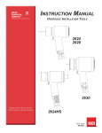
This Instruction manual covers the following installation
tools. Where components other than the installation tools are
mentioned, such as the Single Tool Controller and the
Powerig, please refer to those individual instruction manuals.
TOOLS:
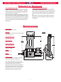
Where pictorial examples are given, the tool used is the HS52RM. See
individual tool assembly drawings in this manual for other configurations.
HS52RM
HS52-21-0-3-0
HS52-81-0-2-0
HS52-81-0-3-0
HS52-81-0-3-50
HS52RM-1-1-0
HS52RM-1-1-50
SINGLE TOOL CONTROLLER:
125725 Instruction Manual part no. HK998
POWERIGS:
Where pictorial examples are given, the Powerig used is the 918. See individual Powerig instruction manuals for pressure settings and component
identification.
940HS Instruction Manual part no. HK943
940-220HS Instruction Manual part no. HK943
918 series Instruction Manual part no. HK786
POWER SUPPLY:
125727-2 Instruction Manual part no. HK1001
5
Huck-Spin® Series Tooling (HK1076)
Alcoa Fastening Systems
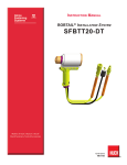
Huck-Spin Part Numbers Structure
HS52 - X X - X - X - X
Custom Options: such as special hose length, etc.
0, 1, 2, 3: Trigger Option ( )
0, 3, 5, 7: Handle Location
0, 1: Air Motor Type ( )
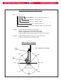
2, 4, 5, 6, 8: Air Motor Location (see figure below)
( ) NOTE:
-0 Option: No Trigger mounted on Hose Guard.
-1 Option: Trigger located on front side of Hose Guard.
-2 Option: Trigger located on rear side of Hose Guard.
-3 Option: Triggers located on both front and rear sides of Hose Guard.
( ) NOTE:
-0 Option: Standard Air Motor used. (NO LONGER AVAILABLE)
-1 Option: Optional high-torque Air Motor used.
HS52 Air Motor Locations
REF: HS52-81-0-3-0 shown
Hose
Guard
0°
Location
8
Location
2
315°
45°
Air
Motor
Location
7
90°
270°
Rear View of Tool
225°
Location
6
135°
180°
Location
5
6
Location
4
Location
3
Huck-Spin® Series Tooling (HK1076)
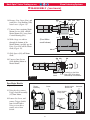
P RINCIPLE
Alcoa Fastening Systems
OF
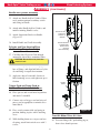
PULL PRESSURE (PULL CYCLE)
During a typical full‐pressure cycle, with the Huck‐Spin
fastener in place and the collar threaded on, the opera‐
tor positions the tool nose assembly over the fastener
pintail and presses the trigger.
The Huck‐Spin tool Thimble spins onto the pin threads
until limit switch rod senses enough engagement, which
then directs pressurized hydraulic fluid into the chamber
in front of the tool’s piston, forcing it back, and pushing
the nose assembly’s Anvil forward to swage the collar
onto the pin.
O PERATION
RETURN PRESSURE (RETURN CYCLE)
When proper swage presure is reached, the hydraulic
pressure will be redirected to the rear of the Piston, and
the Anvil will automatically eject off the swaged Collar,
and the Thimble counter‐rotates to unscrew from the
pin.
This results in all tool and nose assembly components
returning to their home positions, ready to install the
next fastener.
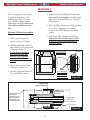
S PECIFICATIONS
POWER SOURCE:
Huck POWERIG Hydraulic Unit
HOSE KITS:
Use only genuine HUCK Hose Kits rated @ 10,000
psi working pressure.
4.7
(12.1)
Inches
(cm)
MAX OPERATING TEMP:
125° F (51.7° C)
MAX FLOW RATE:
2 gpm (7.6 l/m)
7.5
(19)
8.9
(22.6)
MAX INLET PRESSURE:
5,700 psi (393 BAR)
13.2
(33.5)
MAX RETURN PRESSURE:
2,400 psi (165 BAR)
STROKE:
1.808 in. (4.6 cm)
WEIGHT:
17.5 lbs (7.94 kg)
HYDRAULIC FLUID:
ATF meeting DEXRON III, DEXRON IV, MERCON,
Allison C‐4 or equivalent specifications.
12.6
(32)
Fire resistant hydraulic fluid may also be used,
and is required to comply with OSHA regulation
1926.302 paragraph (d): "the fluid used in
hydraulic power tools shall be fire resistant fluid
approved under schedule 30 of the US Bureau of
Mines, Department of Interior, and shall retain its
operating characteristics at the most extreme
temperatures to which it will be exposed."
7
4.4
(11.2)
Huck-Spin® Series Tooling (HK1076)
Alcoa Fastening Systems
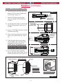
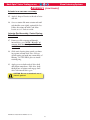
P REPARATION
1. Use Huck Powerig® Hydraulic Unit, or equivalent,
that has been prepared for operation per applicable
instruction manual. Check both PULL and RETURN
pressures and, if required, adjust to pressures given in
SPECIFICATIONS section of this manual.
FOR
U SE
5. Select nose assembly for fastener to be installed.
Disconnect tool control switch electrical cord from
hydraulic unit; disconnect unit from power supply.
Attach nose assembly to tool.
6. Reconnect hydraulic unit to power supply. Reconnect
tool switch control cord to unit. Check operation of
nose assembly; install fasteners in test plate of correct
thickness with proper size holes. Inspect installed fasteners. If fasteners do not pass inspection, see
TROUBLESHOOTING to locate and correct tool malfunction.
WARNING: Correct PULL and RETURN
pressures are required for operator’s
safety and for Installation TooI’s function.
HUCK Pressure Gauge T-124883CE is
available for checking pressures. See Tool
SPECIFICATIONS and Gauge Instruction
Manual. Failure to verify pressures may
result in severe personal injury.
2. First, turn hydraulic unit to OFF, and then, disconnect
power supply from unit. Connect tool hoses to unit.
WARNING: Be sure to connect Tool’s
hydraulic hoses to POWERIG Hydraulic
Unit before connecting Tool’s switch control cord to unit. If not connected in this
order and disconnected in the reverse
order, severe personal Injury may occur.
3. Connect tool control switch electrical cord to hydraulic
unit.
4. Connect hydraulic unit to power supply. Turn unit to
ON. Hold tool trigger depressed for 30 seconds;
depress trigger a few times to cycle tool and to circulate hydraulic fluid. Observe action of tool and check
for leaks. Turn unit to OFF.
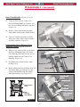
I NSTALLATION S EQUENCE
1. Operator positions Huck-Spin collar onto mating Huck-Spin pin threads by hand.
3. At full pressure, tool swages collar.
4. After swage, anvil is ejected off collar, and
thimble spins off fastener, resulting in all tool
components returning to their home positions.
2. Huck-Spin tool thimble threads onto fastener.
Air motor turns on and, if only Limit Switch 1
is reached, snub routine begins in which collar
is partly swaged, then thimble spins on further
until Limit Switch 2 is closed.
5. Tool is ready to install next Huck-Spin fastener.
8
Huck-Spin® Series Tooling (HK1076)
Alcoa Fastening Systems
M AINTENANCE
•
GOOD SERVICE PRACTICES
CAUTION: Keep dirt and other harmful material out of
hydraulic system, which includes tool, hoses, couplers and POWERIG Hydraulic Unit. Parts must be
kept away from unclean work surfaces. Dirt in
hydraulic system causes valve failure in hydraulic
unit. Individual parts must be handled carefully and
examined for damage or wear. Replace parts where
required. Always replace O-rings and Back-up Rings
when tool is disassembled for any reason.
*
WARNING: Inspect tool for damage or
wear before each use. Do not operate if
damaged or worn, as severe personal
injury may occur.
•
The efficiency and life of your tool depends on
proper maintenance. Using the manual will help
give a clear understanding of the tool and basic
maintenance procedures. Please read this section
completely before proceeding with maintenance
and repair. Use proper hand tools in a clean and
well-lighted area. Only standard hand tools are
required in most cases. Where a special tool is
required, the description and part number are
given.
•
While clamping tool or parts in a vise, and when
parts require force, use suitable soft materials to
cushion impact. For example, using a half-inch
brass drift, wood block and vise with soft jaws
greatly reduces possibility of damaging tool.
Remove components in a straight line without
bending, cocking or undue force. Reassemble tool
with the same care.
Each Service Kit contains perishable parts for your
specific tool. As foreseeable use may indicate,
keep extra kits (O-rings, Back-up Rings, other
standard items) and tool parts in stock. When
stock is depleted, you can get kit items from any
regular retailer of these items. See kit parts list for:
O-ring size (AS568- number); material; durometer.
For kit parts lists and related information, see
General Notes.
DEXRON is a registered trademark of General Motors Corp.
Quintolubric is a registered trademark of Quaker Chemical Corp.
Slic-Tite is a registered trademark of LA-CO Industries, Inc.
TEFLON is a registered trademark of DuPont Corp.
LUBRIPLATE is a registered trademark of Fiske Brothers Refining
Co.
PREVENTIVE MAINTENANCE
System Inspection
Operating efficiency of the tool is directly related to the
performance of the complete system, including the
tool with nose assembly, hydraulic hoses, trigger
switch and control cord, and POWERIG Hydraulic
Unit. Therefore, an effective preventive maintenance
program includes scheduled inspections of the system
to detect and correct minor troubles. At the beginning
of each shift/day:
• Inspect tool and nose assembly for external damage.
• Verify that hydraulic hose fittings, couplings, and
electrical connections are secure.
• Inspect hydraulic hoses for damage and deterioration. Do not use hoses to carry tool. Replace hoses
if damaged.
Consult TROUBLESHOOTING section of this manual if
a malfunction occurs and then see appropriate
ASSEMBLY and/or component illustration sections.
• Observe tool, hoses, and hydraulic unit during
operation to detect abnormal heating, leaks, or
vibration.
Sealants, Lubricants, Hydraulic Fluid & Service
Kits
• Use automatic transmission fluid DEXRON®* III or
equivalent. Fire resistand hydraulic fluid must be
used to comply with OSHA regulation 1926.302
paragraph (d). An optional fire resistand fluid that
may be used is Quintolubric®* 822-220. Fluid viscosity 300 SUS @ 100°F and 50 SUS at 210°F is
recommended for ambient temperatures 0° to 130°
F.
• Max contamination level: NAS 1638 class 9, or ISO
CODE 18/15, or SAE level 6.
•
•
Rub Slic-Tite®* with PTFE thread compound, or
equivalent, on pipe plug threads and quick connect
fitting. CAUTION: Do not use TEFLON®* tape on
pipe threads. Pipe threads may cause tape to
shred resulting in tool malfunction. (Slic-Tite is
available in stick form as Huck P/N 503237.)
•
Smear LUBRIPLATE® 13OAA*, or equivalent lubricant, on O-Rings and mating surfaces to aid assembly and to prevent damage to O-Rings.
(LUBRIPLATE 13O-AA is available in a tube as
Huck P/N 502723.)
POWERIG Hydraulic Unit Maintenance
Refer to the applicable POWERIG instruction manual.
Tool Maintenance
Whenever disassembled and also at regular intervals
(depending on severity and length of use), replace all
seals, wipers, and back-up rings in tool. Service Kits,
hoses, and extra parts should be kept in stock.
Inspect cylinder bore, pistons, and piston rods for
scored surfaces and excessive wear or damage.
Replace as necessary. Always replace seals,
wipers, and back-up rings, and always grease
gears whenever the tool is disassembled for any
reason.
Nose Assembly Maintenance
Clean nose assembly often. Dip in mineral spirits or
similar solvent to clean puller and wash away metal
chips and debris. At regular intervals, as experience
shows, disassemble nose and use a sharp "pick" to
remove imbedded particles from grooves of puller.
9
Huck-Spin® Series Tooling (HK1076)
Alcoa Fastening Systems
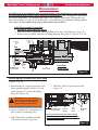
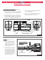
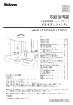
S YSTEM S ET - UP
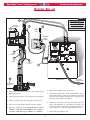
Figure 4
3
2
To Plant
Air Supply
6
To
110VAC
outlet
590434
Timer Codes
Timer 1 Timer 2 Timer 3 Timer 4 Timer 5 Timer 6 Timer 7 Timer 8 -
4
HS52RM shown connected to Single Tool
Controller 125725,
Power Supply 125727-2,
and Powerig 918
Spin ON to LS1
Spin ON from LS1 to LS2
Swage or Snub time (LS2 to Pressure)
Delay after Hyd. Press. Off to Spin Off
Start Spin Off to LS1 Open
Spin On after Snub
Hold Time
Spin Off after LS1 Opens
Error Codes
Trig Rlsd Early Trigger released BEFORE swage complete
-TD-1 Timed out - LS1 NOT reached during Spin ON
-TD-2 Timed out - LS1 NOT reached, go to snub
-TD-3 Time out SN - Pressure NOT reached during Snub
-TD-4 Time out SW - Pressure NOT reached during Swage
-TD-5 Timed out - LS1 NOT Released during spin Off
-TD-6 Timed out - LS2 NOT Made after Snub
-Check Transducer - Transducer NOT connected or FAULTY
-Thimble Cnt. Max. - MAX thimble count has been reached
-Anvil Cnt. Max. MAX anvil count has been reached
125727-2
Power
Supply
PRESSURE
F1 F2 F3 F4
TRIGGER
LIMIT SWITCH 1
LIMIT SWITCH 2
HuckSpin
TOOLCONNECTED
CAUTION
OFF ON
OF
F
CAUTION
TOOL 1
ON
WARNING
CAUTION
CAUTION
CAUTION
8d
POWERIG HYDRAULIC UNIT
LEMO
Connector
8c
Air
Hoses
TOOL 2
CAUTION
CAUTION
24 VAC
8b
Hydraulic
Hoses
TOOL 1
TOOL 2
CAUTION
15 VAC
5
8a
918 Powerig
To primary
power source
Connect to
Nose Assy
6. Plug the Power Supply into a 110V outlet
1. Set pressures on Powerig hydraulic unit using Powerig
instruction manual.
7. Adjust tool settings on the Single Tool Controller (Fig. 5)
for an HS52 with a 5/8 fastener by following instructions
provided in the Controller manual, then set swage pressure
on Single Tool Controller to 5,800psi.
2. Connect primary air source to air fitting at top of Controller.
3. Connect hydraulic hoses from Controller to the Powerig.
8. Install Nose Assembly to the Tool, and attach Tool to the
Single Tool Controller by connecting the hydraulic connectors, the air lines, and the Electric Cable Assembly. The
system will then be ready for the Installation Sequence.
4. Plug electrical cable from Controller to Power Supply.
5. Plug power supply to powerig. NOTE: Be sure to connect
“TOOL 1” from the Power Supply to the “TOOL 1”
receptacle on the Powerig or “TOOL 2” to “TOOL 2”.
9. Turn on Powerig hydraulic unit.
10
Huck-Spin® Series Tooling (HK1076)
Alcoa Fastening Systems
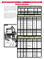
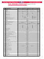
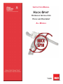
P RESSURE S ETTINGS
These pressures are for Low Swage
Anvils, which can be identified by a
step on the inside bore. Previous
designs of anvils have a straight bore
without any steps and will require higher pressures.
These pressure values are only a starting point for setting the Powerig. Many
factors will cause these pressures to be
higher or lower which can include: tool
condition, hose length, oil temperature
and fasteners being installed.
Figure 5
590434
Timer Codes
Timer 1 Timer 2 Timer 3 Timer 4 Timer 5 Timer 6 Timer 7 Timer 8 -
Spin ON to LS1
Spin ON from LS1 to LS2
Swage or Snub time (LS2 to Pressure)
Delay after Hyd. Press. Off to Spin Off
Start Spin Off to LS1 Open
Spin On after Snub
Hold Time
Spin Off after LS1 Opens
Error Codes
Trig Rlsd Early Trigger released BEFORE swage complete
-TD-1 Timed out - LS1 NOT reached during Spin ON
-TD-2 Timed out - LS1 NOT reached, go to snub
-TD-3 Time out SN - Pressure NOT reached during Snub
-TD-4 Time out SW - Pressure NOT reached during Swage
-TD-5 Timed out - LS1 NOT Released during spin Off
-TD-6 Timed out - LS2 NOT Made after Snub
-Check Transducer - Transducer NOT connected or FAULTY
-Thimble Cnt. Max. - MAX thimble count has been reached
-Anvil Cnt. Max. MAX anvil count has been reached
F1 F2 F3 F4
MENU
DIGIT DIGIT DIGIT
SELECT CHANGE SELECT
HuckSpin
SmallDiameterHuckSpin(Inch)
Fastener
Size
Nose
HS
HS
HS
HS
HS
HS
HS
HS
HS
-8 (1/4")
-10 (5/16")
-10 (5/16")
-12 (3/8")
-12 (3/8")
-10 (5/16")
-10 (5/16")
-12 (3/8")
-12 (3/8")
99-7300
99-7301
99-7304
99-7302
99-7303
99-7506
99-7506CC
99-7609
99-7610
Tool
Notes
HS7
HS7
HS7
HS7
HS7
2580
2580
HSSFT-M10
HSSFT-M10
----------------------------------------------------------------------------------------------------------------------------------------------------------
LargeDiameterHuckSpin(Inch)
Fastener
Size
HS
HS
HS
HS
HS
HS
HS
HS
HS
HS
HS
HS
HS
HS
HS
HS
HS
HS
HS
HS
HS
HS
HS
HS
HS
HS
HS
HS
HS
-16 (1/2")
-20 (5/8")
-16 (1/2")
-16 (1/2")
-16 (1/2")
-16 (1/2")
-16 (1/2")
-16 (1/2")
-16 (1/2")
-20 (5/8")
-20 (5/8")
-20 (5/8")
-20 (5/8")
-20 (5/8")
-24 (3/4")
-24 (3/4")
-32 (1")
-32 (1")
-32 (1")
-16 (1/2")
-20 (5/8")
-20 (5/8")
-20 (5/8")
-16 (1/2")
-16 (1/2")
-20 (5/8")
-20 (5/8")
-24 (3/4")
-24 (3/4")
Nose
99-7330
99-7331
99-7312-1
99-7307-1
99-7308-1
99-7309-1
99-7306-1
99-7313-1
99-7550CC
99-7315-1
99-7551CC
99-7316-1
99-7317-1
99-7318-1
99-7314-1
99-7553CC
99-7321
99-7322
99-7323
99-7600
99-7602
99-7602CC
99-7602-5
99-7500
99-7500CC
99-7501
99-7501CC
99-7503
99-7503CC
Style
Installation - Long
Installation - Long
Installation - Standard
Installation - Long
Installation - Short
Installation - Long
Installation - Standard
Installation - Standard
Removal
Installation - Standard
Removal
Installation - Short
Installation - Long
Installation - Extra Long
Installation - Standard
Removal
Installation - Short
Installation - Standard
Installation - Short
Installation - Standard
Installation - Standard
Removal
Installation - Standard
Installation - Standard
Removal
Installation - Standard
Removal
Installation - Standard
Removal
Tool
Notes
HS24
HS24
HS37
HS37
HS52
HS52
HS52
HS52
HS52
HS52
HS52
HS52
HS52
HS52
HS52
HS52
HS52
HS52
HS52
HSSFT-M12
HSSFT-M16
HSSFT-M16
HSSFT-M16
2624HS/3585PT
2624HS/3585PT
2624HS/3585PT
2624HS/3585PT
2624HS/3585PT
2624HS/3585PT
------------------------------------------------------------------------------------------------------HS37 DIA ANVIL
-------------------------------------------------------------------------------------------------------------------------------------------------------------------------------------------HS Pin & BT Collar
---------------------------------------------------------------------------------------------------------------------------------------------------------------------------
LargeDiameterHuckSpin(Metric)
PRESSURE
TRIGGER
LIMIT SWITCH 1
LIMIT SWITCH 2
TOOLCONNECTED
OFF ON
TURN OFF POWER BEFORE
DISCONNECTING POWER
SUPPLY CABLE
Power
Switch
Style
Installation - Long
Installation - Standard
Installation - Long
Installation - Standard
Installation - Long
Installation - Standard
Removal
Installation - Short
Installation - Long
Fastener
Size
HS
HS
HS
HS
HS
HS
HS
HS
HS
HS
HS
HS
HS
HS
HS
HS
HS
HS
HS
HS
HS
HS
HS
HS
HS
HS
HS
HS
HS
12mm
16mm
12mm
14mm
14mm
12mm
14mm
14mm
16mm
16mm
16mm
16mm
16mm
20mm
20mm
12mm
14mm
14mm
16mm
16mm
16mm
12mm
12mm
14mm
14mm
16mm
16mm
16
20mm
20mm
11
Nose
99-7430
99-7331
99-7412-1
99-7414-1
99-7416-1
99-7413-1
99-7415-1
99-7561CC
99-7315-1
99-7551CC
99-7316-1
99-7317-1
99-7318-1
99-7418-1
99-7562CC
99-7700
99-7702
99-7702-4
99-7602
99-7602CC
99-7602-5
99-7510
99-7510CC
99-7511
99-7511CC
99-7501
99-7501CC
99 7501CC
99-7512
99-7512CC
Style
Installation - Long
Installation - Long
Installation - Standard
Installation - Standard
Installation - Short
Installation - Standard
Installation - Standard
Removal
Installation - Standard
Removal
Installation - Short
Installation - Long
Installation - Extra Long
Installation - Standard
Removal
Installation
Installation - Standard
Installation - Long
Installation - Standard
Removal
Installation - Long
Installation - Standard
Removal
Installation - Standard
Removal
Installation - Standard
Removal
R
l
Installation - Standard
Removal
Tool
Notes
HS24
HS24
HS37
HS37
HS37
HS52
HS52
HS52
HS52
HS52
HS52
HS52
HS52
HS52
HS52
HSSFT-M12
HSSFT-M16
HSSFT-M16
HSSFT-M16
HSSFT-M16
HSSFT-M16
2624HS/3585PT
2624HS/3585PT
2624HS/3585PT
2624HS/3585PT
2624HS/3585PT
2624HS/3585PT
2624HS/3585PT
2624HS/3585PT
--------------------------------------------------------------------------------------------------------------------------------------------------------------------------------------------------------------------------------------------------------------------------------------------------------------------------------------------------------------------------------------------------------------------------------------------------------------------------------------------------------------
Huck-Spin® Series Tooling (HK1076)
S TART - UP
Alcoa Fastening Systems
AND
O PERATION
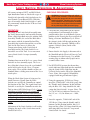
INSTALLING A HUCK-SPIN FASTENER
is released from the installed fastener. If the
tool trigger is released before the installation
cycle is complete, the fastener may not be
properly installed and the system alarm will
sound.
1. Place the Huck-Spin bolt through the workpieces, ensuring that it is the proper grip length
for the workpiece thicknesses to be fastened.
2. Screw a matching size Huck-Spin collar onto
the bolt threads projecting throught the workpieces, and hand-tighten until the flange of the
collar bears against the workpiece surface.
NOTE: For safety reasons, whenever the trigger is
released during any phase of the installation cycle,
the tool automatically reverses and removes itself
from that fastener.
5.
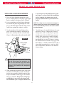
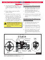
3. Use the handle(s) of the installation tool to
guide it toward the workpiece and locate the
tool’s nose assembly onto the end of the bolt.
(Figure 6) Do not force the tool onto the bolt!
Figure 6
KEEP HANDS
CLEAR
!
WARNING - During fastener installation, the
tool will align itself with the axis of the bolt
and will move toward the workpiece surface. To avoid personal injury, keep hands
clear of all spaces between the tool and the
workpiece and between the workpieces
themselves.
4. While maintaining alignment of the tool’s nose
assembly with the bolt, to avoid cross-threading the nose assembly’s thimble onto the bolt,
depress and hold the tool trigger. The installation cycle will start. Except in an emergency
or difficulty, do not release the trigger until
the installation cycle is complete and the tool
12
Visually inspect the installed fastener for completeness of swage. Compare the measured
“last pressure seen” recorded by the pressure
transducer to the desired full-swage pressure
setting. If the last pressure equals or slightly
exceeds the default setting, a correct installation should have occurred. If unsure, measure
the installed fastener with the swage gage P/N
HG-S-HS(*), or install a similar fastener into a
clamp-load measuring device, such as a skidmore-wilhelm unit, and observe the installed
clamp reading.
Huck-Spin® Series Tooling (HK1076)
Alcoa Fastening Systems
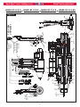
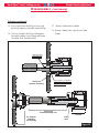
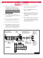
Figure 7a
13
11
43
12
10
9
14
8
37
36
Fig. 7a
Fig. 7b
Fig. 7b
13
14
32
See
Figure 13
44
31
27e
28
29
45
27f
27b
27g
27h
27j
27a 27d
27c 27m
24
26
25(4)
See
Figure 12
23
19
See
Figure 8
22
21
20
18
39
16 (2)
15 (4)
34
(2) 33
(2) 35
17
�
30
38
35
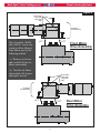
Position Suspension
Bracket (40) to obtain
best balance with
required nose assembly.
HS52RM-1-1-0
27a
2. Item 32, Hydraulic
Assembly, is depicted in
Figure 13 along with its
individual component
identifications.
1
7
6
5
Position Screw (41)
to prevent rotation
of Bracket.
TOP VIEW
of Bracket
�
2
3
4
40
41
42
5
Fig. 7a
HS52RM
2. Item 27, Hydraulic
Assembly, is depicted in
Figure 9 along with its
individual component
identifications.
2. Item 23, Hydraulic
Assembly, is depicted in
Figure 12 along with its
individual component
identifications.
1. Item 22, Drive
Assembly, is depicted in
Figure 8 along with its
individual component
identifications.
Notes:
Huck-Spin® Series Tooling (HK1076)
Alcoa Fastening Systems
HS52RM-1-1-50
Figure 7b
Huck-Spin® Series Tooling (HK1076)
Alcoa Fastening Systems
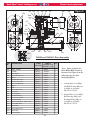
T OOL A SSEMBLY P ARTS L IST (Figures 7a, 7b, 8-13)
ITEM DESCRIPTION
HS52RM HS52RM-1-1-0 HS52RM-1-1-50 QTY
1
Handle
121450
1
2
Trigger
120360
1
3
Electric Cord
505792
20 in.
4
Butt Splice
506817
2
5
Snap Bushing
506101
2
6
Snap Bushing
506100
1
7
Handle Plug
124415
1
8
Hydraulic Hose
9
Suspension Cable Assembly
10
Hydraulic Coupling, male
11
Shackle
12
Hydraulic Coupling, female
13
Control Cable Assembly
14
Twin Tubing
506606
7 ft.
15
Street Elbow
506485
4
16
Tube Connector
505179
2
17
Heat Shrink Tubing
506631
5
18
Trigger Assembly
124110
1
19
Conical Spring
121520
1
20
Retaining Ring
500954
1
21
End Plate
121447
1
22
Drive Assembly (See Figure 8)
23
Switch Assembly (See Figure 12)
124240
1
24
Rubber Plug
506815
2
25
Flat Head Screw 8-32 X 1/2
505588
4
26
Drive Mounting Flange
121529
1
27
Hydraulic Assembly (See Figure 10)
121453
1
28
Split Ring
101577
1
29
Sleeve
101578
1
30
Retaining Ring
502900
1
31
Drive Shaft
121491
1
32
Actuator Rod Assembly (See Figure 13)
121441
1
33
Screw 10-32 X 3/4
500103
2
34
Pipe Plug
502375
1
35
Screw 10-32 X 1-1/4
500106
36
Hose Sleeving
37
Tie Wrap
503541
6
38
Screw 10-32 X 1/2
500101
4
39
HuckSpin Logo Label
590295
2
40
Suspension Bracket
n/a
123626
1
41
Screw
n/a
500134
2
42
Hex Nut
n/a
500237
1
43
Locking Wire
n/a
507041
1 ft.
44
Anvil Adapter
n/a
121406
1
45
O-Ring
n/a
504646
1
123642
123642-50
2
123615-2
123615-3
1
110438
1
506609
507040
110439
124084-60
124490
1
124084-74
124490-1
123724-2
15
1
1
1
4
123724-3
2
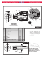
Huck-Spin® Series Tooling (HK1076)
22h 22g
22d
Alcoa Fastening Systems
22f
22e 22d
22b
22c
22a
Figure 8
Shaft
Key
(ref)
22j
22n
22k
22m
22j
22q
(124490-1
only)
22u*
22v*
ITEM
NO.
DESCRIPTION
22w**
22x**
22p
22y**
22t
22r
22s
124490 and 124490-1 Drive Assembly
124490
124491-1
QTY
(HS52RM) (HS52RM-1-1-0
HS52RM-1-1-50)
22a
Muffler, 1/4 NPT
506476
506476
1
22b
Air Motor
121474
121474-1
1
22c
Motor Mount
121405
121405
1
22d
Screw, 10-32 X 1/2L
500101
500101
10
22e
Spacer
121429-2
121429-2
1
22f
External Drive Gear
123741
123741
1
22g
Screw, 6-32 X 1/4L
500047
500047
3
22h
Drive Gear Bushing
121414
121414
1
22j
Spacer
121429-1
121429-1
2
22k
Shaft
123723
123723
1
22m
Screw 10-32 X 5/8L
n/a
500102
4
22n
Gear Cover
121527
121527
1
22p
Retaining Ring
500953
500953
1
22q
Actuator Disk Key
121413
121413
1
22r
Screw, 6-32 X 5/16L
506058
506058
2
22s
Central Housing
123631
123631
1
22t
Socket Head Screw 10-32 X 1/4L
505603
505603
1
22u*
Intermediate Gear
121440
121440
1
22v*
Ball Bearing
506053
506053
2
22w** Internal Drive Gear
127669
127669
1
22x** Ball Bearing
506057
506057
1
22y** Retaining Ring
501495
501495
1
16
Note: Figure 8 depicts the
Rear Motor (RM) version of
the tools. See Figure 9 on the
following page for other
mounting options.
*
Intermediate Gear (22u)
and Ball Bearing (22v) are
available as assembly
Huck P/N 121442.
** Internal Drive Gear (22w),
Ball Bearing (22x), and
Retaining Ring (22y) are
available as assembly
Huck P/N 127670.
Huck-Spin® Series Tooling (HK1076)
Alcoa Fastening Systems
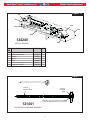
Figure 9
Six Screws
3 this side
3 opposite
side
Air Motor
subassembly
LIFT
Drive Assembly 124490
and 124490-1 can be converted to a Rear Motor or
Front Motor style by the
following method:
LIFT
Front Motor
Drive Assembly
a) Remove six Screws
and carefully lift the Air
Motor subassembly.
b) Turn the Air Motor
subassembly 180 degrees
and replace Screws.
Six Screws
3 this side
3 opposite
side
Air Motor
subassembly
LIFT
LIFT
17
Rear Motor
Drive Assembly
Huck-Spin® Series Tooling (HK1076)
Alcoa Fastening Systems
27g
27f
27b
27a
27c
27e
27k
27h
27d
121453
27j
27m
HYDRAULIC ASSEMBLY
Figure 10
ITEM
NO.
27a
27b*
27c
27d
27e
27f*
27g*
27h*
27j*
27k
27m
DESCRIPTION
PART NO. QTY
Piston & Seal Assembly (see figure below)
Cylinder End Cap
Cylinder
Dump Valve
Wrenching Ring
Wiper
Stepseal
Back-up Ring
O-ring
GLYD Ring Seal (see figure below)
Stepseal
121452
121400
121402
121427
124176
506068
506092
501163
503859
506093
506094
1
1
1
1
1
1
2
1
1
REF
2
Figure 11
121452
Piston Assembly
123865
Piston
Item 27k
GLYD Ring
18
* Items 27b, 27f, 27g, 27h, and
27j may be purchased together as End Cap Assembly part
no. 124422.
Note:
Piston and GLYD Ring are
available separately along
with GLYD Ring Compressor
part no. 123496. GLYD Ring
must be compressed into
Piston groove with GLYD
Ring Compressor if parts are
purchased separately.
Huck-Spin® Series Tooling (HK1076)
Alcoa Fastening Systems
Figure 12
23f
23c
23b
23d
23e
23a
124240
23g
SWITCH ASSEMBLY
ITEM DESCRIPTION
NO.
23a
23b
23c
23d
23e
23f
23g
PART NO. QTY
Printed Circuit Board Assembly
Switch Actuator Slide
Standoff
Spacer
Cover
Button Head Cap Screw 8-32 X .25
Compression Spring
124232
124233
124234
124235
124236
502471
506650
1
1
3
3
1
3
1
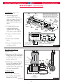
Figure 13
121419
Actuator Rod
121441
121412
Actuator
Disk
Apply two drops of Loctite part no. 505802
to Actuator Rod threads before assembly.
ACTUATOR DISK AND ROD ASSEMBLY
19
20
31
27e
28
29
27f
27h
27j
27a 27d
27c 27m
26
25(4)
23
See
Figure 12
34
19
See
Figure 8
22
21
20
39
�
38
35
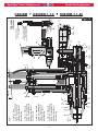
HS52-81-0-3-0
32
44
45
24
A
�
30
27g
(2) 33
HS52-81-0-2-0
See
Figure 13
27a
15
27b
1
A
�
3
TOP VIEW
of Bracket
HS52-21-0-3-0
Position
of motor on
HS52-21-3-0
40
41
42
2
Position Suspension
Bracket (40) to
obtain best balance
5 (2) with required nose
assembly.
6
Position Screw
(41) to prevent
rotation of
Bracket.
Huck-Spin® Series Tooling (HK1076)
Alcoa Fastening Systems
HS52-81-0-3-50
Figure 14
Huck-Spin® Series Tooling (HK1076)
Alcoa Fastening Systems
T OOL A SSEMBLY P ARTS L IST (Figures 7a, 7b, 8-13)
ITEM DESCRIPTION
HS52-21-0-3-0 HS52-81-0-2-0 HS52-81-0-3-0 HS52-81-0-3-50 QTY
1
Handle
121453
2
Trigger
3
Electric Cord
505792
25 in.
5
Snap Bushing
506101
2
6
Snap Bushing
506100
1
120360 QTY: 2 120360 QTY: 1
1
120360 QTY: 2
4
7
8
Hydraulic Hose
9
Suspension Cable Assembly
123642
123642-50
2
123615-2
123615-3
10
Hydraulic Coupling, male
110438
1
1
11
Shackle
507040
1
12
Hydraulic Coupling, female
110439
1
13
Control Cable Assembly
14
Twin Tubing
15
Elbow 3/8 X 1/4 NPT
506677
2
19
Conical Spring
121520
1
20
Retaining Ring
500954
1
21
End Plate
121447
1
22
Drive Assembly (See Figure 8)
124490-1
1
23
Switch Assembly (See Figure 12)
124240
1
24
Drive Mounting Flange
121529
1
25
Flat Head Screw 8-32 X 1/2
505588
4
26
Rubber Plug
506815
2
27
Hydraulic Assembly (See Figure 10)
121453
1
28
Split Ring
101577
1
29
Sleeve
101578
1
30
Retaining Ring
502900
1
31
Drive Shaft
121491
1
32
Actuator Rod Assembly (See Figure 13)
121441
1
33
Screw 10-32 X 3/4
500103
2
34
Pipe Plug
502375
1
35
Screw 10-32 X 1-1/4
36
Hose Sleeving
37
Tie Wrap
503541
6
38
Screw 10-32 X 1/2
500101
4
39
HuckSpin Logo Label
590295
1
40
Suspension Bracket
123626
1
41
Screw
500134
2
42
Hex Nut
500237
1
43
Locking Wire
507041
1 ft.
44
Anvil Adapter
121406
1
45
O-Ring
504646
1
124084-60
124084-74
506606 QTY: 6 ft. 2-1/8 in.
506606 QTY: 8 ft. 2-1/8 in.
1
16
17
18
500106
123724-2
21
2
123724-3
2
Huck-Spin® Series Tooling (HK1076)
Alcoa Fastening Systems
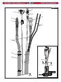
D ISASSEMBLY
Carefully read all precautions in Safe Operation Section. This includes how to safely disconnect
the tool from the power source before starting any maintenance. Refer to appropriate illustrations
and general maintenance. The following procedure is for complete disassembly. Disassemble only
those subassemblies necessary to check and replace worn and damaged components. Always replace
seals, wipers, O-rings and back-up rings of disassembled subassemblies.
Initial Disassembly Preparation
1. Disconnect Tool from power source.
2. Slide Sleeve off of Split Ring. Open Split Ring and remove Anvil Adapter. (Figure 15)
3. Remove Nose Assembly from tool, including Retaining Ring (Item 30, Figures 7b & 14).
a) Slide
Collar
off
32
Actuator Disc
& Rod Assy
b) Open
Split
Ring
c) Remove
Anvil
Adapter
31
Drive Shaft
Rear Motor
Model Shown
Figure 15
Conical Spring; Actuator Rod; Drive Shaft
(Figures 15 & 16)
4. Point Housing in a safe direction and, while
firmly pushing against End Plate (21) and
Conical Spring (19), remove Retaining
Ring (20). (Figure 16)
7. Pull Drive Shaft (31) from front of tool.
(Figure 15)
WARNING: Unless End Plate is
held in firmly, severe personal
injury may occur when Spring
ejects forcibly from Housing.
32
Actuator Disc
& Rod Assy
5. Remove End Plate (21) and Spring (19)
from central Gear Housing (22s).
6. Pull Actuator Disc and Rod Assembly
(32) from rear of tool. (Figure15)
19
Conical
Spring
21
End
Plate
20
Retaining
Ring
Firmly push End Plate against Conical Spring
while removing Retaining Ring to avoid forcible
ejection! See WARNING.
Figure 16
22
Huck-Spin® Series Tooling (HK1076)
Alcoa Fastening Systems
D ISASSEMBLY
Limit Switch (Figure 17)
23e
Cover
8. While holding Switch
Actuator Slide (23b) down
using access hole (Figure 17),
unscrew three Screws (23f)
from Switch Assembly Cover
(23e).
23f
Screw
23c
Standoff
23d
Spacer
23a
Circuit
Board
23g
Spring
YELLOW (LS-1)
GREEN (LS-2)
23b
Switch
Actuator
Slide
{
Trigger - WHITE
RED Trigger
Trigger - BLACK
11. Unscrew three Standoffs
(23c).
BROWN
Top View of Circuit Board
10. Using a screwdriver, disconnect wires.
12. Remove Circuit Board (23a)
and Spacers (23d).
When removing three Screws (23f ),
place the tip of a screwdriver in this
hole to hold down the Switch Actuator
Slide (23b), which will keep it from
popping up from Spring (23g) pressure.
23f
Screw
BLACK 24V+
9. Carefully lift Cover just
enough to hold Switch
Actuator Slide and Spring
(23g) from ejecting suddenly.
( CONTINUED )
Wires to Trigger
Assembly (Rear
Wires to
Control Cable
Assembly
motor models only)
Limit Switch 2
Limit Switch 1
Figure 17
Drive Mounting Flange
(Figures 18-20)
13. Disconnect Air Tubes (14) from
Fittings (Item 15 on front motor
models, Item 16 on rear motor
models). (Figure 18)
14. With hex key, remove both cap
Screws (33) holding the Drive
Mounting Flange (26) to the
Cylinder (27c), and separate the
two main subassemblies.
14
22g
22d 22n
Disconnect
Air Tubes
from Fittings.
(2)
22h
15
Air Motor Drive
15. Remove three Gear Cover
Screws (22g) and two Motor
Mount Screws (22d).
continued
(3)
27c
Handle and Cylinder
Separate two main
subassemblies.
23
26
Drive Mounting Flange
and Air Motor
33
Figure 18
Huck-Spin® Series Tooling (HK1076)
Alcoa Fastening Systems
D ISASSEMBLY
( CONTINUED )
16. Remove Gear Cover (22n), and
push Drive Gear Bushing (22h)
out of cover. (Figure 19)
22d
22c
(4)
22h
22n
17. Unscrew four remaining Motor
Mount Screws (22d), andLift
Motor Mount (22c) away from
Central Housing (22s).
LIFT
LIFT
(Front Motor
18. With a large screwdriver
through the bottom of the
Motor Mount, carefully pry the
Drive Gear (22f) off the Motor
Shaft (Figure 20).
model shown)
22s
Figure 19
19. Slide Spacer (22j) off Motor
Shaft.
22d 22j
Motor
Shaft
Figure 20
Rear Motor Models
(Figure 21)
22f
(4)
20. Unscrew four Screws
(22d) holding Motor to
Motor Mount.
Trigger
Assembly
Screw
21. Using hex key, remove
Trigger Switch Assembly
(18) from Motor.
Carefully pry the Drive
Gear (22f) off the Motor
Shaft with tip of screwdriver.
Switch Holder
Switch side
Setscrew
Switch Holder
Clamp side
2-Conductor
Wire
22. Loosen Set Screw, and
remove Trigger Switch
from Switch Holder.
Using a screwdriver,
remove wires from
Switch.
Figure 21
24
Huck-Spin® Series Tooling (HK1076)
Alcoa Fastening Systems
D ISASSEMBLY
( CONTINUED )
Hose Guard/Handle (Figures 22 & 23)
23. Using an Allen wrench, remove two
Screws holding Handle to Cylinder, and
two Screws holding both halves together.
(Figure 22)
24. Remove Cable Suspension Assembly
from handle, and separate Handle halves.
25. Unscrew Couplers from Hoses. Drain
fluid, then remove Hoses from Cylinder
and drain cylinder. (Figure 23)
Intermediate Gear & Bearing; Drive
Mounting Flange (Figures 24 & 25)
Figure 22
26. With hex key, unscrew four screws holding Drive Mounting Flange to Central
Gear Housing, then unscrew four screws
holding Motor boss on Central Gear
Housing. (Figure 24)
27. Lift Motor boss off and remove shaft
locking screw.
Cylinder
Couplers
Handle half
28. While pulling Shaft out of Motor boss, lift
out intermediate gear and spacers, and
remove both Ball Bearing Assemblies
from Intermediate Gear. (Figure 25)
Hoses
Figure 23
Central Gear
Housing
Intermediate
Gear
Spacer
Intermediate
Gear
Ball
Bearing
Assemblies
Screws
holding Motor
boss to
Central Gear
Housing
Drive
Mounting
Flange
(Screws at
back side)
Figure 25
25
Shaft
Figure 24
Huck-Spin® Series Tooling (HK1076)
Alcoa Fastening Systems
D ISASSEMBLY
( CONTINUED )
Internal Drive Gear & Bearing (Figure 26)
31. With a soft dowel, tap/push Internal Drive
Gear out of Housing.
29. Using a hex key, remove two Screws holding
Actuator Disk Key within Central Housing.
32. Remove the smaller Retaining Ring and the
Ball Bearing from the Drive Gear.
30. With TRUARC pliers, remove the larger of
the two Retaining Rings; the one which holds
the Drive Gear Assembly in the Housing.
Actuator
Disk Key
Screw
Smaller Retaining Ring
Internal
Drive Gear
Ball
Bearing
(Holds Ball Bearing against Gear)
Larger Retaining Ring
(Holds Gear and Bearing in place)
Figure 26
Cylinder (Figures 27 & 28)
33. Remove Locking Disc from
Piston, and screw Piston
Assembly Tool, Huck part
number 124178, onto end of
Piston. (Figure 27)
34. Slide Pin Spanner Assembly,
Huck part number 123607,
over Piston Assembly Tool,
and align dowels with holes at
face of Cylinder End Cap.
Press Spanner Assembly into
End Cap. (Figure 28)
Unscrew Locking Disc from
Piston before installing Piston
Assembly Tool.
124178
Piston Assembly Tool
Piston
Figure 27
26
Huck-Spin® Series Tooling (HK1076)
Alcoa Fastening Systems
D ISASSEMBLY
( CONTINUED )
Cylinder (continued)
35. Screw two Socket Head Cap Screws (supplied with Spanner Assembly) into End Cap.
37. Remove Piston from Cylinder.
38. Remove Dump Valve and all seals from
Piston.
36. Unscrew Cylinder End Cap with Spanner
Assembly, sliding it over Piston and Piston
Assembly Tool, and drain fluid.
Tighten Screws
(one each side)
Align dowels of Spanner
Assembly with holes in End
Cap, and press in.
123607 Pin
Spanner Assembly
Piston and
Piston Assembly Tool
Cylinder
Dump
Valve
Pin Spanner
Assembly
and End Cap
Figure 28
27
Huck-Spin® Series Tooling (HK1076)
Alcoa Fastening Systems
A SSEMBLY
Refer to appropriate illustrations
and general maintenance. The
following procedure is for complete assembly. Always replace
seals, wipers, O-rings and back-up
rings of disassembled subassemblies.
5. Slightly stretch GLYD Ring seal (no more
than needed for installation), liberally apply
lubricant to it, then install it over O-ring in
Piston groove.
6. Slide Glyd Ring Compressor, Huck part number 123496, completely over Piston to
compress the GLYD Ring into the Piston
groove.
Cylinder & Piston Assemblies
(Figures 28-32)
7. Slide Dump Valve through Piston flange.
Important: Flats of Valve must be positioned toward the unthreaded end of
Piston as shown.
1. Inspect and clean out seal
grooves at base of Cylinder.
2. Liberally apply lubricant to Orings and Step Seals, and install
as shown in Figure 29.
NOTE: Before installing
Step Seals, be sure that
notch of seal is oriented
toward inside of Cylinder as
shown.
Inspect and clean
out Seal grooves.
3. Inspect and clean out Piston
seal groove. (Figure 30)
O-rings
Step
Seals
Install Step Seals
so that notches of
Seals are toward
inside of Cylinder.
4. Liberally apply lubricant to Oring, and install in groove.
Figure 29
123496 GLYD
Ring Compressor
GLYD Ring
O-ring
Slide GLYD Ring
Compressor
completely across
Piston to press
GLYD Ring into
the Piston groove
Dump Valve
flats must
face rearward
Figure 30
28
Huck-Spin® Series Tooling (HK1076)
Alcoa Fastening Systems
A SSEMBLY
( CONTINUED )
Cylinder & Piston Assemblies (cont.)
8.
Install Piston Insertion Plug, Huck part
number 123494, in back (unthreaded)
end of Piston. (Figure 31)
9.
Install GLYD Ring Insertion Tool,
Huck part number 121694-HS52, in
Cylinder.
10. Push Piston into Cylinder so that Piston
Insertion Plug protrudes from rear of
Cylinder.
Figure 31
123494 Piston
Insertion Plug
121694-HS52
GLYD Ring
Insertion Tool
11. Remove GLYD Ring Insertion Tool and
Piston Insertion Plug.
Piston Insertion
Plug must
protrude from
back end of
Cylinder
12. Inspect and clean internal and external
grooves of Cylinder End Cap. (Figure
32)
13. Liberally apply lubricant to O-rings,
Back-up Ring, Wiper and Step Seals,
and install as shown in Figure 32.
NOTE: Before installing Step Seals,
be sure that notch of seal is oriented
toward inside of End Cap as shown.
14. Screw Piston Assembly Tool onto
Piston, and slide Cylinder End Cap over
Piston Assembly Tool. (See Figure 28)
Cylinder End Cap
Inspect and clean
out all Seal grooves.
O-rings
Step Seals
Install Step Seals
so that notches of
Seals are toward
inside of Cylinder.
Back-up
Ring
O-ring
Wiper
Fold internal seals as shown
above for easiest insertion.
Figure 32
29
Huck-Spin® Series Tooling (HK1076)
Alcoa Fastening Systems
A SSEMBLY
( CONTINUED )
15. Using Pin Spanner Assembly, screw
Cylinder End Cap onto Cylinder, and tighten until Cap bottoms on Cylinder. (Figure
28)
Internal Drive Gear & Bearing Assembly
18. Pack Bearing with bearing grease, press it
into shoulder of Internal Drive Gear, and
install Retaining Rings. (Figure 33)
19. Grease Bearing and Gear assembly, and
press it into Gear Housing.
16. Remove Piston Assembly Tool and Pin
Spanner Assembly.
17. Thread Hoses onto Cylinder as shown in
Figures 7a, 7b, and 14. (Screw Hose with
male nipple into port “P” of Cylinder, and
hose with female coupler into port marked
“R”.) Rub Slic-Tite® TEFLON® thread
compound, or equivalent, on pipe threads to
prevent leaks and for ease of assembly.
20. Install Actuator Disk Key in housing. Apply
Loctite® to both screws and tighten to specification.
Intermediate Drive Gear & Bearing Assy;
Drive Mounting Flange (Figure 33)
21. Pack Bearings with bearing grease and
press flush into Intermediate Gear.
CAUTION: Do not use TEFLON® tape on
pipe threads. Pipe threads may cause tape
to shred resulting in tool malfunction.
(Slic-Tite is available in stick form as Huck
P/N 503237.)
22. While pushing Shaft through motor boss,
install Intermediate Gear and Spacers, and
tighten Shaft Locking Screw against Shaft.
23. Attach Drive Mounting Flange to central
Housing with eight Screws. Apply blue
Loctite to threads and tighten to specification.
Drive Mounting Flange
Bearing
Spacer
Shaft
Intermediate Gear
Retaining Ring
Shaft
Locking
Screw
(Spirolox type)
Screws
Retaining Ring
Internal Drive Gear
Screws
(Truarc type)
Ball Bearing
Slic-tite is a registered trademark of LA-CO Industries, Inc.
TEFLON is a registered trademark of E. I. du Pont de Nemours and Company
Loctite is a registered trademark of Henkel Corporation, U.S.A.
30
Actuator
Disk Key
Figure 33
Huck-Spin® Series Tooling (HK1076)
A SSEMBLY
Alcoa Fastening Systems
( CONTINUED )
24. Apply Slic-Tite to male threads of Air
Motor Elbows and Muffler, then screw
components into Air Motor and tighten.
Note: Flat on base of motor must be positioned for Intermediate Gear clearance.
Flat is parallel with base of Motor Mount
and shows in mount.
29. Push shoulder of Drive Gear Bushing into
Gear Cover until it snaps in place.
30. Slide assembled Bushing and Cover over
Drive Gear shoulder.
31. Align Gear Cover Mounting holes with
Motor Mount holes, apply Loctite to Gear
Cover Retaining Screws, and tighten to
specification.
25. Place MotorMount over Motor, apply
Loctite to four remaining Screws, and tighten to specification.
32. Place assembled Air Motor and Mount on
Drive Gear and Bearing Assembly, apply
Loctite to Motor Mount Reatining Screws
and tighten to specification.
26. Apply Loctite to four Air Motor retaining
Screws and tighten to specification.
27. Slide white Spacer over Air Motor shaft.
28. After applying bearing grease to teeth of
External Drive Gear and lubricating Gear
shoulder and bore, align key with keyway,
and press Drive Gear onto Motor Shaft.
Elbows and Muffler
Apply SLICTITE to
threads before assembly.
Air
Motor
Motor
Mount
Retaining
Screws
White
Spacer
External Drive Gear
Apply bearing grease to teeth,
and lubricate shoulder and
bore prior to assembly.
Motor
Shaft
Motor
Mount
Air Motor
Retaining Screws
Apply LOCTITE to
threads before assembly.
Gear Cover
with
Drive Gear
Bushing
snapped in place
Gear Cover
Retaining
Screws
Apply LOCTITE to
threads before
assembly.
(Front Motor
model shown)
Figure 34
31
Huck-Spin® Series Tooling (HK1076)
A SSEMBLY
Alcoa Fastening Systems
( CONTINUED )
Handle and Cylinder Assembly
33. Attach one Handle half to Cylinder. Where
used, position optional secondary switch
and wiring in Handle.
34. Attach other Handle half to Cylinder, and
install remaining Handle screws.
Position Screw
to prevent
rotation of
Bracket.
35. Attach Suspension Bracket to Handle.
(Figure 35)
36. Install Handle and Cradle Assembly.
Position Bracket
to obtain best
balance with
required
Nose Assembly
Cylinder and Gear Housing/Drive
Mounting Flange Assembly
37. Carefully slide Electrical Cord through
appropriate slot of drive mounting flange.
CAUTION: Be careful not to pinch the
electrical cord.
38. When cord is properly routed, engage pilot
bore of flange, and align bolt holes of cylinder and flange in required orientation.
39. Apply one drop of removable Loctite to
both retainaing screws, and tighten to specification.
Handle
Halves
Trigger Cord and Power Cord to
Terminal Block; Limit Switch Cover
40. Place spacers and circuit board in position,
and attach 3 standoffs.
41. Connect wires of trigger cord and wires of
power cord to appropriate terminals of terminal block.
42. Place switch actuator slide and spring in
position, holding in place while attaching
cover.
Figure 35
Front Air Motor Drive; Air Lines
43. While holding down cover to prevent loss
of spring, attach limit switch cover with 3
screws.
44. Press on fitting with ; push tubing ing in;
then release thumb pressure.
32
Huck-Spin® Series Tooling (HK1076)
A SSEMBLY
Alcoa Fastening Systems
( CONTINUED )
Actuator Disk and Rod Assembly
45. Apply 2 drops of Loctite to threads of actuator rod.
46. Screw actuator disk onto actuator rod until
rod shoulder seats tightly against disk face.
Follow directions on bottle, and allow
Loctite to “set” for best results.
Actuator Rod Assembly; Conical Spring;
Drive Shaft
47. From rear, slide actuator rod through
internal drive gear. NOTE: “Keyway” of
actuator disk must be aligned with actuator disk key.
48. Slide conical spring into central gear housing against actuator disk. Place end cap
against spring and push into counterbore of
housing. Use TRUARC® pliers to install
retaining ring.
49. Apply grease to both ends of drive shaft
and piston counterbore. Slide drive shaft
through bore of piston, and engage shaft
drive with internal drive gear.
CAUTION: Be sure counterbored area of
piston is greased.
TRUARC is a trademark of TRUARC Co. LLC
33
Huck-Spin® Series Tooling (HK1076)
Alcoa Fastening Systems
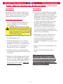
L IMIT S WITCH O PERATION & A DJUSTMENT
All current variants of HS37 and HS52 HuckSpin Installation Tools are fitted with a type of
Limit Switch Assembly which includes an electrical Printed Circuit Board (PCB). With this
type of Assembly, both Limit Switches 1 and 2
are permanently attached to the PCB at a fixed
distance apart.
CHECKING PROCEDURE:
OPERATION
The fitting of the Limit Switch Assembly onto
the Tool is shown on the tool assembly drawing.
When a Huck-Spin Bolt enters the rotating Nose
Assembly Thimble, the end of the Bolt comes
into contact with the Actuator Rod and Disc
Assembly that is pushed toward the rear of the
Tool. As the Disc moves, it allows the
Compression Spring in the Limit Switch
Assembly to move the Limit Switch Lever
toward the rear of the Tool. Lever movement
causes Limit Switch 1 to open (normally
closed).
1. Check that the Tool Piston is in the full forward position. It will normally be in this
position unless there is an Hydraulic System
problem or the Powerig has been switched off
during a Fastener Installation Cycle. When
the piston is in the full forward position, the
front of the Nose Assembly Thimble will be
approx. 0.20-inch (5mm) inside of the
Swaging Anvil.
WARNING: During checking and adjustment of limit switches, it will be necessary
to insert the gauge into the nose assembly
thimble by hand. Therefore, the air supply
at the manifold and the electrical Powerig
cord at the Powerig should be disconnected to prevent possible personal injury.
2. Ensure that the Air Supply is disconnected at
the Manifold and the Electrical Powerig Cord
is disconnected at the Powerig. Use suitable
warning flags to inform other people not to
reconnect those items.
Continued movement of the Lever causes Limit
Switch 2 to close (normally open). The Lever
has a Slot that is located over the rear Standoff
and is held in place by the Cover. Clearance
between the Cover and the shoulder of the rear
Standoff allows a sliding movement of the Lever
to take place.
3. For HUCK-SPIN systems that do not have
switch indicator lights built into the manifold,
plug the Limit Switch Light Box into the
electrical Socket on the side of the Manifold
Cover, (Note: Not required if Manifold is
equipped with integral Indicator Lights.)
When the Huck-Spin System is being used to
install Fasteners, signals from the Limit
Switches are used by the Controller to control
the function of the Tool. The signal from Limit
Switch 2 is used by the Controller to make the
Tool go into a full Collar Swage Cycle. Correct
adjustment of Limit Switch 2 is essential for
proper tool function. Incorrect adjustment will
result in malfunction and may cause insufficient
Collar Swage or failure to release the Tool from
the Bolt at the completion of the Installation
Cycle.
4. Using the appropriate 123940-(xx) Gauge,
insert the ''TOUCH-OFF'' side of the gauge into
the Thimble until it bottoms. In this position
only the Blue LS-1 lamp should be on, indicating that Limit Switch 1 is open. (Note: The
"xx" in 123940-(xx) indicates fastener size;
for 1/2", xx = -16; for 20mm, xx = -M20,
etc.)
5. Insert the opposite, ''TOUCH-ON'' end of the
123940-(xx) Gauge into the thimble until it
bottoms. In this position both the blue LS-1
lamp and the yellow LS-2 lamp should be on,
indicating that Limit Switch 1 is open and
Limit Switch 2 is closed.
continued
Adjustment of the Limit Switches is affected by
changing the angle of the Switch Arms on the
Limit Switch Lever.
34
Huck-Spin® Series Tooling (HK1076)
Alcoa Fastening Systems
L IMIT S WITCH O PERATION & A DJUSTMENT
( CONTINUED )
ADJUSTMENT
REASSEMBLY
Normally it is only necessary to adjust the setting of Limit Switch 2. However, when adjustment is complete, always check Limit Switch 1
again and adjust that Switch if necessary.
6. Insert either end of the Limit Switch Setting
Gauge into the front of the Nose Assembly to
push the Actuator Rod rearward. Hold the
Spring in place on its locator tab at the end of
the PCB. Place the Lever's locating tab into
the opposite end of the Spring. Push the
Lever forward and downward, compressing
the Spring, until it locates onto the rear
Standoff. Make sure that the long Lever 2
Arm is located IN FRONT of the Actuator
Disk. Remove the Gauge from the Nose
Assembly, releasing the Actuator Rod. The
Lever should be pushed forward against Limit
Switch 1 by the small Spring.
TO ADJUST LIMIT SWITCH 2
1. Remove ONLY the TWO Retaining Screws
nearest the FRONT of the Tool from the
Limit Switch Cover.
CAUTION: The limit switch cover retains
the limit switch lever in place against the
compression of a small spring. Give care
when removing the cover to avoid forcible
ejection of the lever and spring from their
normal working positions.
7. Holding the Lever in place, slide the Cover
over the PCB from the rear of the Tool
towards the front of the Tool. When the
Cover is correctly located on the three
Standoffs, it will hold the Lever in the correct
position.
2. Hold the Cover in position while removing
the third Retaining Screw.
3. Slowly lift and slide the Cover toward the
rear of the Tool until the Lever is exposed.
Holding the Lever in place, continue to slide
the Cover toward the rear of the Tool and
then upwards to remove it completely.
8. Replace the three Screws that hold the Cover
in Place.
4. Carefully ease the Lever upwards from the
Switch Assembly making sure that the Spring
is restrained.
9. Re-check the Limit Switch operation as
before.
NOTE: Some Switch Covers may have a
small hole that exposes the Lever (Switch
Actuator Slide). This hole can ease installation of the Cover by placing a small screwdriver or hex key through the hole in the
Cover and bearing it against the Lever while
sliding the Cover into position.
5. Make the necessary adjustment to the Limit
Switch Lever Arms. Hold the top section of
the Lever in a vice or Wide Nose Grips/Pliers
to ensure that only the Limit Switch Arms
bend as shown on the Drawing. Make only
small adjustments at a time.
35
Huck-Spin® Series Tooling (HK1076)
K ITS
AND
Alcoa Fastening Systems
A CCESSORIES
Cylinder Assy 121453 Seal Kit -
HS52SEALKIT
Screw Kit
HS52SCREWKIT
-
Tools Kit (Hex Keys, Pliers, etc.)-
HS52TOOLKIT
Air Motor Kit
121474KIT
-
T ROUBLESHOOTING
Always check the simplest possible cause of a malfunction
first (example: a loose or disconnected trigger line). Then
proceed logically and eliminate each possible cause until
the defect is found. Where possible, substitute known good
parts for suspected defective parts. Use the following steps
as an aid in troubleshooting.
7. Pull grooves on fastener pintail stripped during PULL
stroke.
a. Operator not sliding anvil completely onto fastener
pintail.
b. Incorrect fastener grip.
c. Worn or damaged jaw segments.
d. Metal particles in jaw grooves.
e. Excessive sheet gap.
1. Tool fails to operate when trigger is pressed.
a. Inoperative POWERIG® Hydraulic Unit. See applicable instruction manual.
b. Loose electrical connections.
c. Damaged trigger assembly.
d. Loose or faulty hose coupling.
8. Collar of fastener not completely swaged.
a. Improper tool operation. See No. 6.
b. Scored anvil.
9. Tool "hangs up" on swaged collar of fastener.
a. Improper tool operation. See No. 6.
b. RETURN pressure too low.
c. Not enough collar lubricant.
d. Nose assembly not installed correctly.
2. Tool operates in reverse.
a. Reversed hose connections between hydraulic unit
and tool.
3. Tool leaks hydraulic fluid.
a. Defective tool O-rings or loose connections at tool.
10. Pintail of fastener fails to break.
a. Improper tool operation. See No. 6.
b. Pull grooves on fastener stripped. See No. 7.
c. PULL pressure too low.
4. Hydraulic couplers leak fluid.
a. Damaged or worn O-rings in Coupler Body Coupler
5. Hydraulic fluid overheats.
a. Unit not operating properly. See units manual.
b. Unit running in reverse (918; 918-5 only). See unit’s
manual.
11. Nose will not release broken pintail.
a. Nose assembly not installed correctly.
6. Tool operates erratically and fails to install fastener properly.
a. Low or erratic hydraulic pressure. Air in system.
b. Damaged or worn Piston O-ring in tool.
c. Excessive wear on sliding surfaces of tool parts.
36
Huck-Spin® Series Tooling (HK1076)
Alcoa Fastening Systems
L IMITED W ARRANTIES
MANUFACTURED BY THIRD PARTIES. HUCK
EXPRESSLY DISCLAIMS ANY WARRANTY
EXPRESSED OR IMPLIED, AS TO THE CONDITION, DESIGN, OPERATION, MERCHANTABILITY
OR FITNESS FOR USE OF ANY TOOL, PART(S),
OR OTHER ITEMS THEREOF NOT MANUFACTURED BY HUCK. HUCK SHALL NOT BE LIABLE
FOR ANY LOSS OR DAMAGE, DIRECTLY OR INDIRECTLY, ARISING FROM THE USE OF SUCH
TOOLING, PART(S) OR OTHER ITEMS OR
BREACH OF WARRANTY OR FOR ANY CLAIM
FOR INCIDENTAL OR CONSEQUENTIAL DAMAGES.
TOOLING WARRANTY:
Huck warrants that tooling and other items (excluding
fasteners, and hereinafter referred as "other items")
manufactured by Huck shall be free from defects in
workmanship and materials for a period of ninety (90)
days from the date of original purchase.
WARRANTY ON "NON
STANDARD OR CUSTOM
MANUFACTURED PRODUCTS":
With regard to non-standard products or custom manufactured products to customer's specifications, Huck
warrants for a period of ninety (90) days from the date
of purchase that such products shall meet Buyer's
specifications, be free of defects in workmanship and
materials. Such warranty shall not be effective with
respect to non-standard or custom products manufactured using buyer-supplied molds, material, tooling
and fixtures that are not in good condition or repair
and suitable for their intended purpose.
The only warranties made with respect to such tool,
part(s) or other items thereof are those made by the
manufacturer thereof and Huck agrees to cooperate
with Buyer in enforcing such warranties when such
action is necessary.
Huck shall not be liable for any loss or damage resulting from delays or nonfulfillment of orders owing to
strikes, fires, accidents, transportation companies or
for any reason or reasons beyond the control of the
Huck or its suppliers.
THERE ARE NO WARRANTIES WHICH EXTEND
BEYOND THE DESCRIPTION ON THE FACE
HEREOF. HUCK MAKES NO OTHER WARRANTIES AND EXPRESSLY DISCLAIMS ANY
OTHER WARRANTIES, INCLUDING IMPLIED
WARRANTIES AS TO MERCHANTABILITY OR AS
TO THE FITNESS OF THE TOOLING, OTHER
ITEMS, NONSTANDARD OR CUSTOM MANUFACTURED PRODUCTS FOR ANY PARTICULAR PURPOSE AND HUCK SHALL NOT BE LIABLE FOR
ANY LOSS OR DAMAGE, DIRECTLY OR INDIRECTLY, ARISING FROM THE USE OF SUCH
TOOLING, OTHER ITEMS, NONSTANDARD OR
CUSTOM MANUFACTURED PRODUCTS OR
BREACH OF WARRANTY OR FOR ANY CLAIM
FOR INCIDENTAL OR CONSEQUENTIAL DAMAGES.
HUCK INSTALLATION EQUIPMENT:
Huck International, Inc. reserves the right to make
changes in specifications and design and to discontinue models without notice.
Huck Installation Equipment should be serviced by
trained service technicians only.
Always give the Serial Number of the equipment
when corresponding or ordering service parts.
Complete repair facilities are maintained by Huck
International, Inc. Please contact one of the offices
listed below.
Huck's sole liability and Buyer's exclusive remedy for
any breach of warranty shall be limited, at Huck's
option, to replacement or repair, at FOB Huck's plant,
of Huck manufactured tooling, other items, nonstandard or custom products found to be defective in
specifications, workmanship and materials not otherwise the direct or indirect cause of Buyer supplied
molds, material, tooling or fixtures. Buyer shall give
Huck written notice of claims for defects within the
ninety (90) day warranty period for tooling, other
items, nonstandard or custom products described
above and Huck shall inspect products for which such
claim is made.
TOOLING, PART(S) AND OTHER ITEMS
FACTURED BY HUCK:
Eastern
One Corporate Drive Kingston, New York 12401-0250
Telephone (845) 331-7300 FAX (845) 334-7333
Outside USA and Canada
Contact your nearest Huck International Office, see
back cover.
In addition to the above repair facilities, there are
Authorized Tool Service Centers (ATSC's) located
throughout the United States. These service centers
offer repair services, spare parts, Service Parts Kits,
Service Tools Kits and Nose Assemblies. Please contact your Huck Representative or the nearest Huck
office listed on the back cover for the ATSC in your
area.
NOT MANU-
HUCK MAKES NO WARRANTY WITH RESPECT
TO THE TOOLING, PART(S) OR OTHER ITEMS
37
For the Long Haul™
A Global Organization
Alcoa Fastening Systems (AFS) maintains
company offices throughout the United States
and Canada, with subsidiary offices in many
other countries. Authorized AFS distributors
are also located in many of the world’s
Industrial and Aerospace centers, where they
provide a ready source of AFS fasteners,
installation tools, tool parts, and application
assistance.
Alcoa Fastening Systems world-wide locations:
Americas
Far East
Europe
Alcoa Fastening Systems
Alcoa Fastening Systems
Alcoa Fastening Systems
Alcoa Fastening Systems
Aerospace Products
Tucson Operations
3724 East Columbia
Tucson, AZ 85714
800‐234‐4825
520‐747‐9898
FAX: 520‐748‐2142
Industrial Products
Kingston Operations
1 Corporate Drive
Kingston, NY 12401
800‐278‐4825
845‐331‐7300
FAX: 845‐334‐7333
Industrial Products
Australia Operations
14 Viewtech Place
Rowville, Victoria
Australia 3178
03‐764‐5500
Toll Free: 008‐335‐030
FAX: 03‐764‐5510
Industrial Products
United Kingdom Operations
Unit C, Stafford Park 7
Telford, Shropshire
England TF3 3BQ
01952‐290011
FAX: 0952‐290459
Alcoa Fastening Systems
Alcoa Fastening Systems
Aerospace Products
Carson Operations
PO Box 5268
900 Watson Center Rd.
Carson, CA 90749
800‐421‐1459
310‐830‐8200
FAX: 310‐830‐1436
Industrial Products
Latin America Operations
Avenida Parque Lira. 79‐402
Tacubaya Mexico, D.F.
C.P. 11850
FAX: 525‐515‐1776
TELEX: 1173530 LUKSME
Alcoa Fastening Systems
NOTICE: The information contained in this publi‐
cation is only for general guidance with regard to
properties of the products shown and/or the
Aerospace Products
France Operations
Clos D’Asseville
BP4
95450 Us Par Vigny
France
33‐1‐30‐27‐9500
FAX: 33‐1‐34‐66‐0600
Certified to
ISO 9001:2008
Industrial Products
Waco Operations
PO Box 8117
8001 Imperial Drive
Waco, TX 76714‐8117
800‐388‐4825
254‐776‐2000
FAX: 254‐751‐5259
For The Long Haul, The Future of Fastening
Technology, The Future of Assembly Technology,
The Future of Tooling Technology, and Tools of
Productivity are service marks of Huck
International. Huck provides technical assistance
regarding the use and application of Huck fasten‐
ers and tooling.
Alcoa Fastening Systems
Industrial
Products
Industrial
Products
Certified to
ISO 14001:2004
means for selecting such products, and is not
intended to create any warranty, express,
implied, or statutory; all warranties are contained
only in Huck’s written quotations, acknowledge‐
ments, and/or purchase orders. It is recommend‐
ed that the user secure specific, up‐to‐date data
and information regarding each application
and/or use of such products.
HWB898 1003‐5M
One Great ConnectionSM
© 2003 Alcoa Fastening Systems
1 Corporate Drive, Kingston, NY 12401 • Tel: 800‐431‐3091 • Fax: 845‐334‐7333 • www.alcoafasteningsystems.com