1
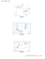
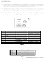
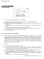
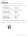
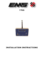
7703
INSTALLATION INSTRUCTIONS
EMS SYSTEM 7000
Table of Contents
Section
Page No
1. INTRODUCTION ............................................................................................................ 3
2. INSTALLATION INSTRUCTIONS....................................................................................... 5
3. INSTALLATION NOTES................................................................................................... 8
3.1 RADIO INTERFERENCE. .................................................................................................. 8
3.2 RADIO RANGE. ........................................................................................................... 8
4. FUNCTIONS AND FEATURES .......................................................................................... 9
4.1 CLEAR MEMORY ........................................................................................................... 9
4.2 LOAD TRANSMITTER SERIAL IDENTITIES ............................................................................. 9
4.3 DELETE TRANSMITTER IDENTITY ......................................................................................10
5. USER INSTRUCTIONS ..................................................................................................10
5.1 INSTRUCTIONS ...........................................................................................................10
5.2 AUDIBLE WARNING .....................................................................................................10
5.3 KEYSWITCH ..............................................................................................................11
5.4 VISUAL INSTRUCTIONS .................................................................................................11
5.5 TAMPER AERIAL..........................................................................................................12
5.6 RADIO INTERFERENCE LED.............................................................................................12
5.7 ANTI-FALSE ALARM ......................................................................................................12
6. TRANSMITTER OPERATION............................................................................................13
7. TECHNICAL INFORMATION FOR THE 7703 RECEIVER .......................................................14
2
7703 INSTALLATION, ISSUE V2.2 – 13/04/10
EMS SYSTEM 7000
1. Introduction
1.1
The UHF singleway radio is ideal for use in all types of financial, or commercial premises
where staff need the security of a personal attack system and also the freedom of mobility.
The 7703 is a versatile compact UHF receiver for use with a selection of transmitters. These
receivers can store up to 48 transmitter identification numbers.
1.2 There are 3 types of transmitter which are compatible with the 7703 these are, the portable,
the money clip and a contact operated model, each have a typical range of 250 metres.
The alkaline battery fitted will offer approximately one year’s battery life, dependent on
frequency of use.
A brief list of the features offered by the 7703 receiver is as follows:
(a) LED display of Alarm, local and transmitter battery low.
(b) Radio blocking interference detection.
(c) Aerial tamper detection.
(d) Anti false alarm.
(e) Power supply failure warning.
(f)
Key switch for clear, reset and test.
(g) Outputs from programmable Alarm and Local relays.
(h) Low power operation.
(i) Programmable audio warning.
1.3 The internal view of the 7703 receiver is shown below in Figures 1, 2 and 3.
3
7703 INSTALLATION, ISSUE V2.2 – 13/04/10
EMS SYSTEM 7000
Figure 1
Figure 2
Figure 3
4
7703 INSTALLATION, ISSUE V2.2 – 13/04/10
EMS SYSTEM 7000
2. Installation Instructions
Before installing the 7703 receiver read these instructions with care.
2.1 When choosing a suitable site for the 7703 consider the following:(a)
(b)
The minimum recommended distance of metal objects or equipment from the aerial is
400mm.
The minimum recommended distance to photocopiers, computers and fax machines is
2 metres.
2m
FIXING SURFACE / WALL
2m
2m
2m
DO NOT RUN CABLE
DIRECTLY BEHIND
AERIALS
400mm
2m
2m
2m
2m
7703 RECEIVER
TO BE MOUNTED AT LEAST 2m AWAY FROM OTHER
ELECTRICAL DEVICES
2.2 Having chosen a suitable site, place the receiver in or near its final position. Fit the special
aerial provided and connect power to the receiver as per the provided connection drawing.
On power-up the 7703 will self test. The self test will cause the internal sounder to sound for
approximately 1 second. In addition the front panel LED's will light momentarily in the
following order: Clear LED, Test LED, Power LED, Radio Interference LED, Low
Battery LED, Local LED and Alarm LED. This cycle will be repeated a number of times.
The number of repetitions determines the state of the receiver as shown in Table 1.
Cycles
3
3
1
Radio Status
EEPROM OK. Clear LED steady means transmitters in memory
EEPROM OK. Clear LED flashing means no transmitter's in
memory
EEPROM failure
Table 1
The above sequence of events will also occur if the reset button on the receiver board is
pressed.
2.3 To check for radio interference using the integral carrier detector, turn the keyswitch to the
TEST position. The red RADIO INTERFERENCE LED will light if spurious radio signals are
present. Re-site the 7703 if necessary.
2.4 Load the serial identities of the transmitters to be used with the system, see section 4.2.
2.5 Check the signal from each transmitter can reach the receiver from their intended locations.
5
7703 INSTALLATION, ISSUE V2.2 – 13/04/10
EMS SYSTEM 7000
2.6 If the front panel has not already been unscrewed, undo and remove the 4 screws holding
the front panel to the main body of the receiver. Disconnect power and remove the battery if
fitted. The front panel will now be suspended from the black retaining strap.
2.7
Hold the receiver body in its final position and mark the 4 fixing holes. Knock out the
appropriate cable entry point to allow connections to be made to the receiver. Ensure that
the cable entry point selected affords the shortest possible cable run inside the receiver.
2.8 Reconnect the power cable and battery connections removed in 2.6 above. Before replacing
the front panel select the appropriate Receiver and Buzzer options using the switches as
shown below in accordance with Tables 2, 3 and 4 which outline the available options.
Switch
1
Function
Local Relay
Switch On
Latched
Switch Off
On
for
period
of
transmission + 2 seconds
N/O going closed
2
3
Contact
type
Buzzer
Alarm Buzzer permitted
Alarm Buzzer Inhibited
4
Alarm Relay
Latched
5
Buzzer
6
Contact transmitters
On
for
period
of
transmission + 2 seconds
No
buzzer
for
valid
transmissions
Alarm
transmitter N/C going open
Buzzer
for
period
transmission + 1 second
Local
of
Table 2
Switches 7 and 8 are used to select the type of transmitter being used
SW
7
Off
Off
ON
SW8
Off
ON
OFF
Transmitter Type
Opposed Buttons for Full Alarm
Three Buttons for Full Alarm
Non Opposed Buttons for Full Alarm
Table 3
6
7703 INSTALLATION, ISSUE V2.2 – 13/04/10
EMS SYSTEM 7000
Switch
1
Buzzer follows Alarm LED
Switch On
2
Buzzer Follows Local LED
3
Buzzer sounds for 4 seconds in Clear and Test
4
Buzzer Follows Low Battery LED
5
6
Buzzer sounds when receiving any valid transmission with key in TEST
Buzzer follows RI LED (not with Key in TEST)
7
Buzzer sounds on mains fail
8
Buzzer follows Local LED but with 5 second delay
Table 4
2.9 Check all options, functions and relays operate correctly.
shown in Table 5.
Transmitter Operation
Green button pressed
Both side buttons pressed
The relays should operate as
Relay Operation
Local relay operates.
Alarm, relay operates.
Table 5
2.10 Re-check 2.5.
2.11 Holding the front panel to the main body of the receiver add the 4 screws previously
removed.
7
7703 INSTALLATION, ISSUE V2.2 – 13/04/10
EMS SYSTEM 7000
3. Installation Notes
3.1 Radio Interference.
3.1.1 Door access systems, photocopiers, fax machines, modems, processor controlled security
controllers and digital telephone exchanges are a few of the items that on occasion may
emit spurious signals. If the spurious emissions correspond to the co-channel or adjacent
channel frequencies, they may interfere with the performance despite the careful 7703
receiver design.
3.1.2 Two meters distance from the aerial is usually sufficient to eliminate their effects but door
access systems have been known to require a greater distance. Do not over look the
possibility of there being apparatus on the opposite side of the wall to which the receiver is
to be installed, which is not the property of the installation site.
3.1.3 With TEST mode selected the RADIO INTERFERENCE LED is connected to an integral
carrier detector. This detector will turn ON if any radio signal exceeding -110 DBM is found
within the channel used by the 7703.
3.2 Radio Range.
3.2.1 The expected range of a transmitter may not be achieved for a variety of reasons. The
local environment is normally responsible and a few of these reasons are as follows:(a)
(b)
(c)
(d)
(e)
Radio interference.
Metal tiled floors, walls or ceilings.
Metal framed suspended ceilings.
Metal foil wall covering under the decorations used for thermal insulation
Metal objects or equipment on the opposite side of the wall to which the receiver
is installed.
Problems caused by the above may be reduced by:(1)
(2)
Re-siting the receiver.
Fitting a remote aerial.
8
7703 INSTALLATION, ISSUE V2.2 – 13/04/10
EMS SYSTEM 7000
4. Functions and Features
4.1 Clear Memory
To clear the transmitter serial ident Memory as follows:
(a)
(b)
(c)
(d)
(e)
(f)
(g)
Detach the front panel from the case leaving all the connecting cables intact.
Select RESET mode with the key switch.
Depress and hold both the transmitter ADD and DELETE switches adjacent to the
processor.
Momentarily depresses the MASTER RESET switch adjacent to the transmitter DELETE
switch.
When the buzzer has bleeped 3 times release the switches.
Select CLEAR mode using the keyswitch. The green CLEAR LED will flash if the routine
was completed correctly, otherwise repeat from (b).
Refit the front panel.
4.2 Load Transmitter Serial Identities
4.2.1 For the 7703 to recognise the transmitters assigned to it the identity of each transmitter
must be stored in its memory. The memory can store up to 48 different numbers. Each
transmitter has a unique number and there are 2 methods for loading the receiver's nonvolatile memory with these numbers. There is a time limit of 5 seconds each for loading
and confirming a transmitter's indent number, five flashes of the Red Alarm (load) or
green local (confirm) LED’s respectively. When the Red Alarm LED flashes for loading,
transmit using a Local signal (see Table 5). (The same signal must be used for
confirmation as was used for loading).
4.2.2 Method
(a)
(b)
(c)
(d)
(e)
Select RESET mode using the key switch:
Turn the key to TEST and back to RESET position 3 times. Allow not more than 1
second between switching actions. The Red Alarm LED will flash showing the MEMORY
is now open for loading the transmitter ident number.
Activate a transmitter, using a Local activation. If the ident is accepted the green Local
LED will flash asking for confirmation and a long bleep will be heard.
Activate a transmitter again, using a Local activation. If the confirmation is accepted 3
short bleeps will be heard and the Yellow Low Battery LED will flash to acknowledge
storage.
Repeat from (a) for each transmitter ident to be loaded.
9
7703 INSTALLATION, ISSUE V2.2 – 13/04/10
EMS SYSTEM 7000
Notes:
If the Green LED flashes only once, the confirmation signal did not match the Load signal.
Repeat from (a).
If the Yellow LED does not flash to acknowledge storage, the identity number is already
stored in the memory.
The POWER LED will turn off during the loading routine.
4.3 Delete Transmitter Identity
(a)
(b)
(c)
(d)
(e)
(f)
(g)
With either CLEAR or TEST mode selected:
Depress and hold the internal transmitter DELETE switch.
Select RESET mode using the key switch. The Green Local LED will flash.
Release the DELETE switch. The MEMORY is now open for deleting the ident number.
Activate a transmitter, using a Local activation. If the ident is accepted the Red Alarm
LED will flash asking for confirmation and a long bleep will be heard.
Activate a transmitter again, using a Local activation. If the confirmation is accepted 3
short bleeps will be heard and the Yellow Low Battery LED will flash to acknowledge
deletion.
Repeat from (a) for each transmitter ident to be deleted.
Notes:
To delete a specific transmitter number the transmitter must be available and routine 4.3
used. When a transmitter is lost, the 7703's Memory must be cleared using routine 4.1 and
the transmitter serial ident number re-loaded using routine 4.2.
5. User Instructions
5.1 Instructions
Though the 7703 has many features it is very easy to use. Any of the visual indicators can
be accompanies with an audible warning but these would normally be selected at the time of
installation. The only user control is the key switch. The 7703 will only recognise the
transmitters whose identity numbers have been stored in it's memory. The identity numbers
will remain safely stored in the memory, even in the event of total power failure.
5.2 Audible Warning
5.2.1 Audible warning can be selected to accompany any of the visual indicators in addition,
special selections can be made as follows :
5.2.2 Five second delay of warning.
5.2.3 Clear mode not set, bleeps 3 times every 2 minutes. Any of the above selections are best
made and initialised at the time of commissioning. These are made using the internal
switches.
10
7703 INSTALLATION, ISSUE V2.2 – 13/04/10
EMS SYSTEM 7000
5.3 Keyswitch
5.3.1 With the keyswitch in the CLEAR position, the green CLEAR and Amber POWER LED's are
ON.
This signifies the 7703 is active and waiting for signals from the assigned
transmitters. If a signal is received at the same time of switching from reset to clear the
anti-false alarm function will hold the 7703 in test (with the alarm relay locked) until the
signal ceases, when clear mode will automatically be activated.
5.3.2 Turning the keyswitch to RESET will cancel all functions activated. The display will be
cleared and all LED's will return to their normal status: i.e.,
(a)
(b)
(c)
(d)
The CLEAR LED will be of OFF.
The relays will be held inactive, no alarm can be caused.
An active audible warning will be turned OFF.
An audible warning will bleep 3 times every 2 minutes to indicate CLEAR mode is
NOT selected.
5.3.3 With the keyswitch turned to the TEST position this allows the 7703 and its assigned
transmitters to be tested. The relays will be held inactive, no alarm can be caused,
although "Full" alarm, "Local" alarm and "Low Battery" LED’s will respond to signals from
the transmitters.
The display LED’s will momentarily operate and the audible warning will operate if the
options were previously selected.
5.4 Visual Instructions
(a)
CLEAR: Green "clear" LED on and steady signifies the system is active, waiting for an
Alarm signal. This LED will turn off if a "Full" or "Local" alarm is received. The "Clear" LED
will flash if the memory block for recording the identity of the system transmitter identities
is empty.
(b)
TEST : Red "test" LED on signifies the system is ready for testing. The relays are locked
and cannot cause an alarm. The radio interference LED will light if a system transmitter in
range is operated or, for any radio interfering signal tuned to the same channel as the
receiver.
(c)
ALARM: When an alarm signal is received the RED alarm LED will light and alarm relay deenergise. The LED will remain on until system is reset. The user can select for latching or
momentary operation of the alarm relay at the time of commissioning.
(d)
LOCAL: When a "Local" signal is received the GREEN local LED will light and local relay
energise. The LED will remain on until the system is reset. The user can select for latching
or momentary operation of the local relay at the time of commissioning.
(e)
LOW BATTERY: The amber LED will flash to indicate when the receiver battery or the DC
supply is low. The LED will continuously light if a low battery signal is received from a
transmitter.
(f)
POWER: The power LED is ON when the unit is powered from the mains and FLASHES if
the mains is interrupted. This is latched, if the interruption is for more than 4 minutes. It
will remain latched until the key is turned to the RESET position.
11
7703 INSTALLATION, ISSUE V2.2 – 13/04/10
EMS SYSTEM 7000
(g)
RADIO INTERFERENCE: KEY IN CLEAR. 30 seconds of an unrecognisable signal will
cause the RED RFI LED to turn on. The LED will flash if the signal ceases. Thereafter, the
LED will light steadily for any RF interference signal which exceeds one second. Turn the
key to reset to clear the display. With the KEY IN TEST, the RFI LED will follow any RF
signal. It is possible to receive a valid alarm with no Carrier Detect occurring, as the
receiver can decode valid data where the carrier is 10DB below the Carrier Detect level.
5.5 Tamper Aerial
5.5.1 The aerial supplied with the 7703 is special and should not be substituted for any other
aerial, unless it has been recommended by E.M.S Limited. Should the aerial be cut or
removed from its BNC connector a LOCAL ALARM will be signalled. If the buzzer option is
selected the audible warning will operate continuously, see Buzzer Option table 4. The
LOCAL ALARM can only be cleared by installing a serviceable aerial of the same type.
5.6 Radio Interference LED
5.6.1 With TEST mode selected the Red RADIO INTERFERENCE LED will light if any radio signal
tuned to the channel used by the 7703 is received. This includes the transmitters assigned
to the 7703. With CLEAR mode selected the RADIO INTERFERENCE LED will light if an
interfering radio signal is received for a period exceeding 30 seconds. This only applies to
signals not recognised by the 7703.
5.7 Anti-false Alarm
5.7.1 Should an ALARM or LOCAL signal be received at the same time as CLEAR mode is
selected, the Anti-false alarm routine will take control and hold the 7703 in the TEST
routine until the signal terminates. During the waiting period the Green CLEAR LED will
remain OFF, the Red TEST LED will be ON and the Red RADIO INTERFERENCE will be ON
announcing the presence of an unwanted signal. Providing the CLEAR mode remains
selected, when the signal terminates the 7703 will then automatically release the TEST
routine and change to CLEAR mode. Only the green CLEAR LED and Amber POWER LED
will remain ON.
12
7703 INSTALLATION, ISSUE V2.2 – 13/04/10
EMS SYSTEM 7000
6. Transmitter Operation
6.1
The following instructions show the operation of the 7900 hand held transmitters.
6.2
The portable transmitter shown below operates in the following manner when configured to
work as opposed action:
Green pushbutton pressed
Red pushbutton pressed
Both red buttons pressed together
6.3
Local alarm Initiated
No effect
Full alarm Initiated
If the transmitter is configured to work as non-opposed action, the operation is;
Green pushbutton pressed
Red pushbutton pressed
Both red buttons pressed together
Green and either red button pressed
6.4
Local alarm Initiated
No effect
No effect
Full alarm Initiated
If the transmitter is configured to work as triple action, the operation is;
Green pushbutton pressed
Red pushbutton pressed
Both red buttons pressed together
Green and either red button pressed
All three buttons pressed
Local alarm Initiated
No effect
No effect
No effect
Full alarm initiated
6.5
Alarm Latch memory, if on pressing a single red button the Red Light indicates on the
handset, a full alarm has been initiated from the hand push within the last 12 hours.
6.6
Battery low is indicated by the yellow light coming on when a local or alarm activation is
sent.
GREEN
BUTTON
RED
BUTTON
RED
BUTTON
13
7703 INSTALLATION, ISSUE V2.2 – 13/04/10
EMS SYSTEM 7000
7. Technical Information For The 7703 Receiver
Dimensions:
Weight of 7703 (DC version)
Operating Frequency:
Channel Spacing:
Modulation:
Deviation:
Sensitivity:
R.S.S.I:
A.F.C:
Antenna Input:
Radio Blocking Detection:
Power of 7703:
Low supply flag at:
Relay contact rating:
Operation Temperature:
Humidity:
230mm x 150mm x 68mm
1.4 G (Without Battery)
458.50 to 458.80 MHZ (MPT 1329)
25 KHZ
FSK NBFM
+/- 2.4 KHZ
-120 DBM for 12 DB SINAD
Analogue, Dynamic range 80 DBM
+/- 3 KHZ
50R
Signals exceeding -110 DBM
240 VAC 50 HZ at 7.5 VA
10.5 or 21 VDC selectable
24 VDC at 1 AMP MAX, 28VA
-10 to 55 degrees centigrade
Up to 75% non Condensing.
14
7703 INSTALLATION, ISSUE V2.2 – 13/04/10
EMS SYSTEM 7000
15
7703 INSTALLATION, ISSUE V2.2 – 13/04/10
EMS SYSTEM 7000
Dealer Information:
EMS Group Head Office
Technology House,
Sea Street
Herne Bay,
Kent CT6 8JZ
England
Tel: +44 (0) 8712 710804
Fax: +44 (0) 1227 369679
Email: [email protected]
The information contained within this literature is
correct at time of publishing. The EMS Group
reserves the right to change any information
regarding products as part of its continual
development enhancing new technology and
reliability. The EMS Group advises that any product
literature issue numbers are checked with its head
office prior to any formal specifications being written.
www.emsgroup.co.uk
16
7703 INSTALLATION, ISSUE V2.2 – 13/04/10