1
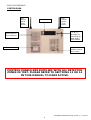
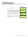
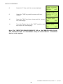
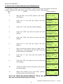
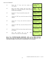
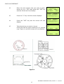
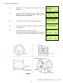
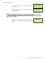
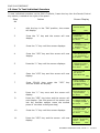
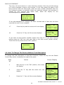
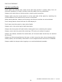
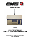
5000
ENGINEERS OPERATING GUIDE
EMS 5000 FIREPOINT
Table of Contents
Section
Page No
1. HOW TO RESET FIRE & FAULT EVENTS. ............................................................................ 6
2. HOW TO ENTER THE SYSTEM EVENT LOG ......................................................................... 7
3. HOW TO ENTER THE SYSTEM EVENT LOG WITH FAULTS DISPLAYED.................................... 8
4. HOW TO DISABLE DEVICES ............................................................................................ 9
5. HOW TO RE-INSTATE DEVICES FROM DISABLEMENT ....................................................... 11
6. HOW TO DISABLE A DEVICE ACROSS A NETWORK SYSTEM .............................................. 12
7. HOW TO RE-INSTATE A DISABLED DEVICE ACROSS A NETWORK ...................................... 14
8. HOW TO LOG ON A DEVICE .......................................................................................... 16
9. HOW TO REMOVE A DEVICE.......................................................................................... 18
10. HOW TO REPLACE DEVICES ........................................................................................ 20
11. HOW TO PUT DETECTOR ZONES INTO TEST (TESTING DEVICES) .................................... 23
12. HOW TO TAKE DETECTOR ZONES OUT OF TEST ............................................................ 25
13. HOW TO PUT ALL THE ZONES INTO TEST ACROSS A NETWORK....................................... 26
14. HOW TO TAKE ALL THE ZONES OUT OF TEST ACROSS A NETWORK ................................. 28
15. HOW TO TEST INDIVIDUAL SOUNDERS ........................................................................ 30
16. HOW TO CHANGE THE DEVICE ADDRESS TEXT DESCRIPTION ......................................... 32
17. RECOMMENDED ADDITIONAL SOUNDER MONITORING ................................................... 34
18. FAULT LIST ............................................................................................................... 35
19. DO’S AND DON’TS ..................................................................................................... 36
ENGINEERS OPERATING GUIDE, ISSUE 3.0 – 16/08/10
3
EMS 5000 FIREPOINT
SYSTEM 5000
VHF
Helical
Aerial
(R/X)
Yellow
Display
UHF
Helical
Aerial
(T/X)
Green
“∆” & “∇”
Arrows For
scrolling up
and down
the menus
Zoned LED for
Fire Indication
Thermal Printer
Keypad &
Panels Control
Key switch
CONTROL PANELS ARE SUPPLIED WITH ALL DETECTOR
ZONES IN TEST. PLEASE REFER TO SECTIONS 12 OR 14
IN THIS MANUAL TO MAKE ACTIVE.
ENGINEERS OPERATING GUIDE, ISSUE 3.0 – 16/08/10
4
Pins & Access
User Log On
View Users
Change PIN
Add 6 Digit User
Add 4 Digit User
Edit User
Delete User
Access And Buzzer
User Options Order
Front Screen Text
Site Address Text
Delete All Users!
EMS 5000 FIREPOINT
Options Menu Structure
Key in “OFF” position
with Password Entered:
-
Time/Date
Set the Time
View the Date
Set the Date
View BST/GMT
Set BST/GMT
Day-Night Ctrl
Event Logging
View Log At Date
View Entire Log
View Log Group
Print Log By Date
Print Entire Log
Processor Resets
Options
Passwords
Time and Date
Logging
Fire System Opts
Checksum Info
Radio Lan Opts
Lan Control
Fire System
Dev. Disable/Test
Net. Disable/Test
Det Zone
Disable/Test
Alarm Zone Disable
ARE Disable
System Mode
Engineers Config
Checksum Ctrl
View Checksums
Monitor Checksums
Radio LAN
Node Table
Re-Start Lan
Re-Online Node
Node Setup
View/Delete Node
Advanced
LAN Fire DB
H/W Local Panels
Mimic
Advanced
ENGINEERS OPERATING GUIDE, ISSUE 3.0 – 16/08/10
5
EMS 5000 FIREPOINT
1. How To Reset Fire & Fault Events.
To reset fires/faults on the 5000 FirePoint, insert the Key into the Panel’s Control Key
switch, located at the right of the Panel. Turn the Key to the “ON” Position.
Step
No
1
Action
Screen Display
01 FIRE ALARM TOT 01
RADIO CALLPOINT
This a normal Fire Event
ZONE 01
2
3
4
Press the “SILENCE ALARMS” button and the
screen will now briefly display: (Press Any
Key). Having silenced the System’s Sounders
and Internal Buzzers, an intermittent beep
every 10 – 15 seconds will occur until reset.
Press the “RESET/LED TEST” button and the
screen will now briefly display: (Press Any
Key)
The Event is now clear, so the key switch can
be returned to the “OFF” position. The screen
will now display:
DEVICE 005
Alarms Silenced
Push Any Key
Device RESET:
RADIO CALLPOINT
Push Any Key
Status Normal
Date
Time
ENGINEERS OPERATING GUIDE, ISSUE 3.0 – 16/08/10
6
EMS 5000 FIREPOINT
2. How To Enter The System Event Log
To enter the Systems Event Log on the 5000 FirePoint, insert the key into the Panels
Control Key switch, located at the right of the panel. Turn the key to the”ON” position.
Step
No
1
2
3
Action
Screen Display
With the key in the “ON” position, the screen
will display:
Panel in Access
Date
Time
Press the “0” key and the screen will now
display:
|***Options **** |
>Passwords
<
|Time and Date
|
Yes =Select
Time
Press the “∇” key until the screen displays:
|Time and Date
|
>Logging
<
|Fire System Opts |
YES = Select
Time
|**Event Logging *
4
Press the “YES” key and the screen will now
display:
5
Press the “YES” key and the screen will now
display:
6
Enter the required date to view in
dd/mm/yy Format, (e.g.28/05/03) then press
the “YES” key and the screen will now display:
|
>View Log At Date<
|View Entire Log |
Yes = Select
Time
Enter the date to
View:
/ /
Yes = Finish
Time
---------------On 28/05/03 At 00:00
New Day of 28/05/03
Yes = Select
Time
The log for the date selected can be viewed by using the “∆” & “∇” Arrows next to the
display, all fire and fault events are listed in date and time order. Using number 5 on the
keypad will take you to the oldest event, number 8 on the keypad will take you to the
latest event. (Look at the fault list for examples of descriptions that are in the log)
ENGINEERS OPERATING GUIDE, ISSUE 3.0 – 16/08/10
7
EMS 5000 FIREPOINT
3. How To Enter The System Event Log With Faults Displayed
To enter the system event log on the 5000 FirePoint with faults displayed there are two
ways.
The first way is to disable the devices that are in fault then enter the logging in the first
menu. The second way is to enter the engineer’s menu main. To enter the engineer’s
main menu insert the key into the Panels Control Key switch, located at the right of the
Panel and turn it to the “ON” position.
Step
No
1
2
3
4
Action
Screen Display
With the key in the “ON” position, the screen will
display:
Press the “0”
now display:
key
and
the
screen
will
Press the “∇” key until the screen displays:
Press the “YES” key and the screen will now
display:
01 FAULT
TOT 03
Default Device
001
Zone 01 Device 001
|** Fire system **
|
>Dev. Disable/Test <
| Net. Disable/Test |
Yes= Select
Time
| System Mode
|
> Engineers Config <
| Printer Options |
Yes= Select
Time
Enter Your PIN
For Access>
Then Press YES
Time
|** Eng. Config ** |
>Device Database <
| Sounder Options |
Yes= Select
Time
5
Press 221100 then press the “YES” key and the
screen will display:
6
Press Number 8 on the keypad and the screen
will now display: (number is a quick move key
that takes you to the bottom of the menu)
|
>Lan Options
<
|^^^^^^^^^^^^^^ |
Yes= Select
Time
7
Press the “∆” key until the screen displays:
| Reset Security
|
>Reset System
<
|Lan Options
|
Yes= Select
Time
8
Press the “YES” key followed by the “0” key on
the keypad the screen will now display:
|** Main Menu ** |
>Pins & Access
<
|System Support |
Yes= Select
Time
9
Press the “∇” key until the screen displays:
|Output Setup
>Logging
|Remote Rxers
Yes= Select
10
Press the “YES” key and the screen will now
display:
| Reset System
|
<
|
Time
|**Event Logging * |
>View Log At Date <
| View Entire Log
|
Yes = Select
Time
ENGINEERS OPERATING GUIDE, ISSUE 3.0 – 16/08/10
8
EMS 5000 FIREPOINT
11
12
Press the “YES” key and the screen will now
display:
Enter the required date to view in dd/mm/yy
format, (e.g.28/05/03) then press the “YES”
key and the screen will now display:
Enter the date to
View:
/ /
Yes = Finish
---------------On 28/05/03 At 00:00
New Day of 28/05/03
Yes = Select
The log for the date selected can be viewed by using the “∆
∆” & “∇
∇” Arrows next to the
display, all fire and fault events are listed in date and time order. Using number 5 on the
keypad will take you to the oldest event, number 8 on the keypad will take you to the
latest event. (Look at the fault list for examples of descriptions that are in the log).
4. How To Disable Devices
To disable a device on the 5000 FirePoint, insert the key into the Panels Control Key
switch, located at the right of the Panel. Turn the key to the “ON”
Step
No
1
2
3
4
5
6
7
Action
Screen Display
With the key in the “ON” position, the screen
will display:
“0” key and the screen will now display:
Press the “∇” key until the screen displays:
Panel in Access
Date
Time
|***Options ****
|
>Passwords
<
|Time and Date
|
Yes =Select
Time
| Logging
|
>Fire System Opts<
| Remote Access
|
Yes = select
Time
Press the “YES” key and the screen will now
display:
|** Fire system **
|
>Dev. Disable/Test<
| Net. Disable/Test |
Yes= Select
Time
Press the “YES” key and the screen will now
display:
|** Device Status * |
>Number is: 001 <
|Status is: ACTIVE|
Yes= Select
Time
Press the “0” key and the screen will now
display:
Enter Device
(Number 1-256)
Number > _
Yes = Finish Time
Enter the device number that you want to
Disable (e.g. 125) then
press the “YES” key
and the Screen will now display:
|** Device Status * |
>Number is: 125
<
|Status is: ACTIVE|
Yes= Select
Time
Time
ENGINEERS OPERATING GUIDE, ISSUE 3.0 – 16/08/10
9
EMS 5000 FIREPOINT
8
Press the “∇” key until the screen displays:
9
Press the “YES” key and the screen will now
display:
10
Press the “NO” key three times and the screen
will now display:
11
Turn the Control key to the “OFF” position and
the screen will now display:
|Number is: 125
|
> Status is: ACTIVE<
| Zone is : 01
|
Yes= Select
Time
|Number is: 125
|
>Status is :DISABLE<
| Zone is : 01
|
Yes= Select
Time
Panel in Access
Date
Time
Status Normal
Date
Time
Note: The “DETECTOR/ZONE DISABLED” LED on the 5000 FirePoint Panel
will illuminate with an intermittent beep to show there’s a Disabled
device on the system.
ENGINEERS OPERATING GUIDE, ISSUE 3.0 – 16/08/10
10
EMS 5000 FIREPOINT
5. How To Re-instate Devices From Disablement
To reactivate a device on the 5000 FirePoint, insert the key into the Panels Control Key
switch, located at the right of the panel. Turn the key to the “ON” position.
Step
No
1
2
Action
Screen Display
With the key in the “ON” position, the screen
will display:
Press the “0” key and the screen will now
display:
Panel in Access
Date
Time
|***Options ****
|
>Passwords
<
|Time and Date
|
Yes =Select
Time
| Logging
Press the “∇” key until the Screen displays:
|
>Fire System Opts <
|Remote Access
|
Yes = select
Time
4
Press the “YES” key and the screen will now
display:
|** Fire system **
|
>Dev. Disable/Test <
| Net. Disable/Test |
Yes= Select
Time
5
Press the “YES” key and the screen will now
display:
| ** Device Status * |
>Number is: 001 <
|Status is: ACTIVE |
Yes= Select
Time
6
Press the “0” key and the screen will now
display:
Enter Device
(Number 1-256)
Number > _
Yes = Finish
Time
7
Enter the device number that you want to Reenable (e.g. 125) then press the “YES” key and
the Screen will now display:
| ** Device Status * |
>Number is: 125
<
|Status is: DISABLE|
Yes= Select
Time
Press the “∇” key once and the screen will
display:
|Number is: 125
|
>Status is: DISABLE<
| Zone is : 01
|
Yes= Select
Time
9
Press the “YES” key twice and the screen will
now display:
|Number is: 125
|
>Status is : ACTIVE <
| Zone is : 01
|
Yes= Select
Time
10
Press the “NO” key three times and the screen
will now display:
3
8
Panel in Access
11
Return the Control key to the “OFF” position
and the screen will now display:
Date
Time
Status Normal
Date
Time
Note: The “DETECTOR/ZONE DISABLED” LED on the 5000 FirePoint Panel
will clear and the Disable beep will stop.
ENGINEERS OPERATING GUIDE, ISSUE 3.0 – 16/08/10
11
EMS 5000 FIREPOINT
6. How To Disable A Device Across A Network System
To disable a device across the network on the 5000 FirePoint, insert the key into the
Panels Control Key switch, located at the right of the panel.
Step
Action
Screen Display
No
1
With the key in the “ON” position, the screen
will display:
Panel in Access
Date
2
3
Press the “0” key and the screen will now
display:
Press the “∇” key until the screen displays:
4
Press the “YES” key and the screen will now
display:
5
Press the “∇” key once and the screen will
display:
Time
| ***Options ****
|
>Passwords
<
| Time and Date
|
Yes =Select
Time
| Logging
|
>Fire System Opts <
| Remote Access
|
Yes = select
Time
|** Fire system **
|
> Dev. Disable /Test<
| Net. Disable /Test |
Yes= Select
Time
| Dev. Disable/Test |
>Net. Disable/Test <
| Det Zone Dis/Test |
Yes= Select
Time
|* Network Status * |
6
7
Press the “YES” key and the screen will now
display: (move on to step 8 if H/W)
> Panel Type : PAN <
| Panel
: 00
|
Yes= Select
Time
Press the “YES” key once the Screen will now
display:
|* Network Status * |
> Panel Type : NET <
| Panel
: 00
|
Yes= Select
Time
NOTE: PAN is for a Hardwired based System.
NET is for a Radio LAN based system.
8
Press the “∇” key once and the screen will
display:
9
Press the “YES” key to change the panel
number until the required panel number is
shown: (e.g. 04)
10
Press the “∇” key once and the screen will
display:
| Panel Type : PAN |
> Panel
: 00
<
| Device
: 00
|
Yes= Select
Time
| Panel Type : NET |
> Panel
: 04
<
| Device
: 00
|
Yes= Select
Time
| Panel
> Device
| Status
Yes= Select
: 04
|
: 00 <
: Active|
Time
ENGINEERS OPERATING GUIDE, ISSUE 3.0 – 16/08/10
12
EMS 5000 FIREPOINT
11
Press the “0”
now display:
key
and
the
screen
will
12
Enter the device number that you want to
Disable (e.g. 125) then press the “YES” key and
screen will now display:
Enter Device
(Number 1-256)
Number > _
Yes = Finish Time
| Panel
: 04
|
>Device
: 125 <
| Status
: Active |
Yes= Select
Time
| Device
: 125
|
> Status : Active <
| Transmit Event
|
Yes= Select
Time
13
Press the “∇” key once and the screen will
display:
14
Press the “YES” key once the screen will now
display:
15
Press the “∇” key once and the screen will
display:
16
Press the “YES” key once the Screen will now
display:
| Device
: 125
|
>Status : Disable<
| Transmit Event
|
Yes= Select
Time
|Status
: Disable |
>Transmit Event <
|^^^^^^^^^^^^^^ |
Yes= Select
Time
Device 125 on NET 04
Set to DISABLED
Push Any Key
17
18
Press the “NO” key three times and the screen
will display:
Turn
the
Control
key
to
the
Position. The screen will now display:
“OFF”
Time
Panel in Access
Date
Time
Status Normal
Date
Time
Note: The “DETECTOR/ZONE DISABLED” LED on the 5000 FirePoint
Master Panel and the 5000 FirePoint Slave Panel 04 will illuminate with
intermittent beep to show there’s a disablement on the system.
ENGINEERS OPERATING GUIDE, ISSUE 3.0 – 16/08/10
13
EMS 5000 FIREPOINT
7. How To Re-instate a Disabled Device Across a Network
To re-instate a Disabled a device across the network on the 5000 FirePoint, insert the
key into the Panels Control Key switch, located at the right of the panel.
Step
Action
Screen Display
No
1
With the key in the “ON” position, the screen
will display:
Panel in Access
Date
2
3
Press the “0” key and the screen will
display:
now
Press the “∇” key until the screen displays:
Time
|***Options ****
|
>Passwords
<
| Time and Date
|
Yes =Select
Time
| Logging
|
>Fire System Opts <
| Remote Access
|
Yes = select
Time
|** Fire system **
4
5
6
Press the “YES” key and the screen
display:
will now
Press the “∇” key until the screen displays:
Press the “YES” key and the screen will now
display:
|
>Dev. Disable/Test <
| Net. Disable/Test |
Yes= Select
Time
| Dev. Disable/Test |
>Net. Disable /Test <
| Det Zone Dis/Test |
Yes= Select
Time
|* Network Status * |
>Panel Type : PAN <
| Panel
: 00
|
Yes= Select
Time
NOTE: PAN is for a Hardwired based System. (Go to step 7).
NET is for a Radio LAN based system. (Go to step 8).
7
Press the “YES” key to select the required panel
type and the Screen will now display:
|* Network Status * |
> Panel Type: NET<
| Panel
: 00
|
Yes= Select
Time
8
Press the “∇” key until the screen will display:
(Where Panel type = NET/PAN)
| Panel Type : NET |
>Panel
: 00
<
| Device
: 00
|
Yes= Select
Time
9
Press the “YES” key to change the panel
number until the required panel number is
shown: (e.g. 04)
| Panel Type : NET |
>Panel
: 04
<
| Device
: 00
|
Yes= Select
Time
10
Press the “∇” key until the screen displays:
|Panel
: 04
|
>Device
: 00
<
|Status
:Disable |
Yes= Select
Time
ENGINEERS OPERATING GUIDE, ISSUE 3.0 – 16/08/10
14
EMS 5000 FIREPOINT
11
Press the “0” key and the screen will now
display:
Enter Device
(Number 1-256)
Number > _
Yes = Finish Time
Time
Enter the device number that you want to reinstate (e.g. 125) then press the “YES” key and
screen will now display:
| Panel
> Device
| Status
Yes= Select
13
Press the “∇” key until the screen displays:
| Device
: 125
|
> Status
:Disable <
| Transmit Event
|
Yes= Select
Time
14
Press the “YES” key once the Screen will now
display:
| Device
: 125
|
> Status : Active <
| Transmit Event
|
Yes= Select
Time
12
: 04
|
: 125 <
:Disable |
Time
| Status
15
16
17
Press the “∇” key until the screen displays:
Press the “YES” key once the Screen will now
display:
Press the “NO” key until the screen displays:
: Active |
>Transmit Event <
| ^^^^^^^^^^^^^^ |
Yes= Select
Time
Device 125 on NET 04
Set to ACTIVE
Push Any Key
Panel in Access
Date
18
Turn the Control key to the “OFF” Position. The
screen will now display:
Time
Time
Status Normal
Date
Time
Note: The “DETECTOR/ZONE DISABLED” LED on the 5000 FirePoint
Master Panel and System 5000 Slave Panel will clear and the Disable beep
will stop.
ENGINEERS OPERATING GUIDE, ISSUE 3.0 – 16/08/10
15
EMS 5000 FIREPOINT
8. How To Log On A Device
To log on a device onto the 5000 FirePoint, take the device in front of the panel. Insert
the key into the Panels Control Key switch, located at the right of the Panel.
Step
No
1
2
Action
Screen Display
With the key in the “ON” position, the screen
will display:
Press the “0” key and the screen will now
display:
Panel in Access
Date
Time
|***Options *** *
|
> Passwords
<
| Time and Date
|
Yes =Select
Time
3
Press the “∇” key until the screen displays:
| Logging
|
> Fire System Opts <
| Remote Access
|
Yes = select
Time
4
Press the “YES” key and the screen will now
display:
|** Fire system **
|
> Dev. Disable /Test<
| Net. Disable /Test |
Yes= Select
Time
5
Press the “∇” key until the screen displays:
| System Mode
|
>Engineers Config <
| Printer Options
|
Yes= Select
Time
6
Press the “YES” key and the screen will now
display:
Enter Your PIN
For Access>
Then Press YES
Time
Press 221100 then press the “YES” key and the
screen will display:
|** Eng.; Config ** |
> Device Database <
| Sounder Options |
Yes= Select
Time
8
Press the “∇” key until the screen displays:
| Sounder Options |
> Log On Devices
<
| Site Survey
|
Yes= Select
Time
9
Press the “YES” key and the screen will now
display:
7
10
11
Press the “YES” key to change and the screen
will now display:
Press the “0” key and the screen will now
display:
Logon DISABLED(000)
Push YES to change
Push NO to escape
Push YES/NO
Time
|**Logon Options** |
> Logon Slot :AUTO<
| Slot is
:FREE |
Yes= Select
Time
Enter Device
(Numbers 1-256)
Number>
Yes= Finish
Time
ENGINEERS OPERATING GUIDE, ISSUE 3.0 – 16/08/10
16
EMS 5000 FIREPOINT
12
13
Enter the slot number that you want to add a
device to (e.g. 125) then press the “YES” key
and the Screen will now display:
Press the “∇” key until the screen displays:
14
Press the “YES” key and the screen will now
display:
15
Take the device you want to log on.
Press and hold the logon button for 2-3 seconds
(e.g. Figure 1) and the screen will now display:
| **Logon Options** |
> Logon Slot :125 <
| Slot is
:FREE |
Yes= Select
Time
| Slot is
:IN USE |
>Logon is DISABLED<
| /\/\/\/\/\/\/\/\/\/\ |
| Slot is
:IN USE |
>Logon is ENABLED <
| /\/\/\/\/\/\/\/\/\/\ |
Logon Default Device
125
Yes= Select
Time
Added Default Device
125
Yes= Select
Time
Figure 1
ENGINEERS OPERATING GUIDE, ISSUE 3.0 – 16/08/10
17
EMS 5000 FIREPOINT
16
Press the “YES” key twice and the screen will
now display:
17
Press the “NO” key three times and the screen
will now display:
| Slot is
:IN USE |
>Logon is DISABLED<
| /\/\/\/\/\/\/\/\/\/\ |
01 FAULT
TOT 02
Default Device 125
ZONE 01 DEVICE 125
Note: After logging the device on to the system there will be two faults:1st fault is processor reset. (Silence and reset E.G. Page 5)
2nd fault is the Tamper. (Make sure the device tamper is clear then silence
and reset E.G. page 5)
18
After the faults have been cleared, turn the
control key to the “OFF” position and the screen
will display:
Status Normal
Date
Time
9. How To Remove A Device
To remove a device from the 5000 FirePoint, insert the key into the Panels Control Key
switch, located at the right of the panel.
Step
Action
Screen Display
No
1
2
3
With the key in the “ON” position, the screen
will display:
Date
Time
Press the “0” key and the screen will now
display:
|***Options ****
|
>Passwords
<
| Time and Date
|
Yes =Select
Time
Press the “∇” key until the screen displays:
| Logging
|
> Fire System Opts <
| Remote Access
|
Yes = select
Time
4
Press the “YES” key and the screen will now
display:
5
Press the “∇” key until the screen displays:
6
Panel in Access
Press the “YES” key and the screen will now
display:
|** Fire system **
|
> Dev. Disable /Test <
| Net. Disable /Test |
Yes= Select
Time
| System Mode
|
> Engineers Config <
| Printer Options
|
Yes= Select
Time
Enter Your PIN
For Access>
Then Press YES
Time
ENGINEERS OPERATING GUIDE, ISSUE 3.0 – 16/08/10
18
EMS 5000 FIREPOINT
7
8
9
10
Press 221100 then press the “YES”
key and the screen will display:
|** Eng.; Config **
|
>Device Database <
| Sounder Options |
Yes= Select
Time
Press the “∇” key until the screen displays:
| Site Survey
|
> Remove Devices <
| Panel Hardware
|
Yes= Select
Time
Press the “YES” key and the screen will now
display:
Enter the device number you want to delete
(e.g. 005) and press the “YES” the screen will
now display:
11
Press ANY key and the screen will display:
12
Press the “NO” key three times and the screen
will now display:
13
Turn the control key to the “OFF” Position. The
screen will now display:
Enter Device
(Numbers 1-256)
Number > _
YES = Finish
Time
Device 5 Deleted
Press Any Key
Time
| Site Survey
|
>Remove Devices <
| Panel Hardware
|
Yes= Select
Time
Panel in Access
Date
Time
Status Normal
Date
Time
ENGINEERS OPERATING GUIDE, ISSUE 3.0 – 16/08/10
19
EMS 5000 FIREPOINT
10. How To Replace Devices
To replace a device onto the 5000 FirePoint, take the new device in front of the panel.
Insert the key into the Panels Control Key switch, located at the right of the panel.
Step
Action
Screen Display
No
1
2
With the key in the “ON” position, the screen
will display:
Press the “0” key and the screen will now
display:
Panel in Access
Date
Time
|***Options ****
|
> Passwords
<
| Time and Date
|
Yes =Select
Time
3
Press the “∇” key until the screen displays:
|Logging
|
>Fire System Opts <
|Remote Access
|
Yes = select
Time
4
Press the “YES” key and the screen will now
display:
|** Fire system * *
|
> Dev. Disable/Test <
| Net. Disable/Test |
Yes= Select
Time
Press the “∇” key until the screen displays:
| System Mode
|
> Engineers Config <
| Printer Options
|
Yes= Select
Time
5
6
7
8
9
10
Press the “YES” key and the screen will now
display:
Press 221100 then press the “YES” key and the
screen will display:
Press the “∇” key until the screen displays:
Press the “YES” key and the screen will now
display:
Press the “YES” key to change and the screen
will now display:
Enter Your PIN
For Access>
Then Press YES
Time
| ** Eng.; Config ** |
> Device Database <
| Sounder Options |
Yes= Select
Time
| Sounder Options |
> Log On Devices <
| Site Survey
|
Yes= Select
Time
Logon DISABLED(000)
Push YES to change
Push NO to escape
Push YES/NO
Time
|**Logon Options** |
> Logon Slot :AUTO<
| Slot is
:FREE |
Yes= Select
Time
ENGINEERS OPERATING GUIDE, ISSUE 3.0 – 16/08/10
20
EMS 5000 FIREPOINT
11
Press the “0” key and the screen will now
display:
Enter Device
(Numbers 1-256)
Number>
Yes= Finish
Time
12
Enter the slot number that you want to add a
device to (e.g. 125) then press “YES” key and
the Screen will now display:
|**Logon Options** |
>Logon Slot :125
<
| Slot is
:FREE |
Yes= Select
Time
13
Press the “∇” key until the screen displays:
14
Press the “YES” key twice and the screen will
now display:
15
Take the device you want to log on.
Press and hold the logon button for 2-3 seconds
(e.g. Figure 2) and the screen will now display:
|Slot is
:IN USE |
>Logon is DISABLED<
| /\/\/\/\/\/\/\/\/\/\ |
|Slot is
:IN USE |
>Logon is REPLACE <
| /\/\/\/\/\/\/\/\/\/\ |
Logon Default Device
125
Yes= Select
Time
Added Default Device
125
Yes= Select
Time
Figure 2
ENGINEERS OPERATING GUIDE, ISSUE 3.0 – 16/08/10
21
EMS 5000 FIREPOINT
16
Press the “YES” key once and the screen will
now display:
17
Press the “NO” key three times and the screen
will now display:
| Slot is
:IN USE |
>Logon is DISABLED<
| /\/\/\/\/\/\/\/\/\/\ |
01 FAULT
TOT 02
Default Device 125
ZONE 01 DEVICE 125
Note: After logging the device on to the system there will be two faults: 1st fault is processor reset. (Silence and reset E.G. Page 3)
2nd fault is the Tamper. (Make sure the device tamper is clear then silence
and reset E.G. page 3)
18
After the faults have been cleared turn the
control key to the “OFF” position. The screen will
display:
Status Normal
Date
Time
ENGINEERS OPERATING GUIDE, ISSUE 3.0 – 16/08/10
22
EMS 5000 FIREPOINT
11. How To Put Detector Zones Into Test (Testing Devices)
To put zones into test for the 5000 FirePoint, insert the key into the Panels Control Key
switch, located at the right of the panel. Turn the key to the “ON” position.
Step
Action
Screen Display
No
1
2
With the key in the “ON” position, the screen
will display:
Press the “0” key and the screen will now
display:
Panel in Access
Date
|***Options ****
> Passwords
| Time and Date
Yes =Select
Time
|
<
|
3
Press the “YES” key and the screen will now
display:
| *PIN’s and ACCESS*|
>User Log ON
<
| View Users
|
Yes =Select
Time
4
Press the “YES” key and the screen will now
display:
Enter Your PIN
To Log On > _
Then Press YES
5
Enter 221100 and press the “YES” key and the
screen will now display:
6
Press
Any
now display:
7
8
key
and
the
screen
will
Press the “∇” key until the screen displays:
Press the “YES” key and the screen will now
display:
Time
******************* *
Welcome Engineer *
********************
Push Any Key
Time
| Logging
|
> Fire System Opts <
| Remote Access
|
Yes= Select
Time
|***Options ****
|
> Passwords
<
| Time and Date
|
Yes =Select
Time
|** Fire system **
|
> Dev. Disable /Test<
| Net. Disable /Test |
Yes= Select
Time
9
Press the “∇” key until the screen displays:
| Net. Disable /Test |
> Det Zone. Dis /Test <
| Alarm Zone Disable |
Yes= Select
Time
10
Press the “YES” key and the screen will now
display:
| ** Zone Status ** |
> Zone is: 01
<
| Status
: ACTIVE |
Yes= Select
Time
ENGINEERS OPERATING GUIDE, ISSUE 3.0 – 16/08/10
23
EMS 5000 FIREPOINT
11
12
Press the “∇” key and the screen will now
display: (Make note of the status the zones is in
e.g. ACTIVE, the status will need to be changed
back Later)
Press the “YES” key twice and the screen will
now display: (notice as the “YES” key is pressed
the status changes)
| Zone is : 01
|
> Status
: ACTIVE <
|^^^^^^^^^^^^^^^^ |
Yes= Select
Time
| Zone is : 01
|
> Status
: Test
<
|^^^^^^^^^^^^^^^^|
Yes= Select
Time
| ** Zone Status ** |
> Zone is: 01
<
| Status : Test
|
Yes= Select
Time
13
Press the “∆” key until the screen displays:
14
Press the “YES” key and the screen will now
display:
| ** Zone Status ** |
> Zone is: 02
<
| Status
: ACTIVE |
Yes= Select
Time
15
Press the “∇” key until the screen displays:
| Zone is : 02
|
> Status
: ACTIVE <
|^^^^^^^^^^^^^^^^ |
Yes= Select
Time
16
Press the “YES” key and the screen
will now display: (notice as the “YES”
key is pressed the status changes)
| Zone is : 02
|
> Status
: Test
<
|^^^^^^^^^^^^^^^^ |
Yes= Select
Time
This needs to be repeated until all the Detector Zones are in test, then
continue to step 18
17
18
Press the “NO” key three times and the screen
will now display:
Turn
the
control
key
to
the
position. The screen will now display:
“OFF”
Panel in Access
Date
Time
Status Normal
Date
Time
The devices are now ready to be activated, this includes smoking
detectors and triggering call points. When a device is activated the 5000
FirePoint will go into fire, the display will show TEST ALARM and display
the device number and text description. The Sounders/Relays will not
activate.
NOTE: When smoking detectors their LEDs stay on for 20 minutes.
NOTE: For multi panel installations all zones on ALL panels must be put
into test before testing is started.
ENGINEERS OPERATING GUIDE, ISSUE 3.0 – 16/08/10
24
EMS 5000 FIREPOINT
12. How To Take Detector Zones Out Of Test
To take zones out of test and back into original state i.e. all on the 5000 FirePoint, insert
the key into the Panels Control Key switch, located at the right of the Panel. Turn the
key to the “ON” Position.
Step
Action
Screen Display
No
1
With the key in the “ON” position, the screen
will display:
2
Press the “0” key and the screen will now
display:
3
Press the
displays:
4
“∇”
key
until
the
screen
Press the “YES” key and the screen will now
display:
5
Press the “∇” key until the screen displays:
6
Press the “YES” key and the screen will now
display:
7
Press the “∇” key once and the screen will now
display:
8
Press the “YES” key twice and the screen will
display: (This puts the status back to ACTIVE)
9
10
Press the “∆” key once and the screen will now
display:
Press the “YES” key and the screen will now
display:
Panel in Access
Date
Time
|***Options ****
|
> Passwords
<
| Time and Date
|
Yes =Select
Time
| Logging
|
>Fire System Opts <
| Remote Access
|
Yes= Select
Time
|** Fire system **
|
> Dev. Disable /Test<
| Net. Disable /Test |
Yes= Select
Time
| Net. Disable /Test |
>Det Zone. Dis /Test <
| Brigade Isolate
|
Yes= Select
Time
| ** Zone Status **
|
> Zone is: 01
<
| Status : Test
|
Yes= Select
Time
| Zone is
: 01
|
> Status : Test
<
| ^^^^^^^^^^^^^^^^|
Yes= Select
Time
| Zone is
: 01
|
> Status : ACTIVE<
| ^^^^^^^^^^^^^^^^|
Yes= Select
Time
| ** Zone Status ** |
> Zone is: 01
<
| Status : ACTIVE |
Yes= Select
Time
| ** Zone Status ** |
> Zone is: 02
<
| Status : Test
|
Yes= Select
Time
ENGINEERS OPERATING GUIDE, ISSUE 3.0 – 16/08/10
25
EMS 5000 FIREPOINT
11
Press the “∇” key once and the screen will now
display:
| Zone is
: 02
|
> Status : Test
<
|^^^^^^^^^^^^^^^^ |
Yes= Select
Time
12
Press the “YES” key twice and the screen will
now display: (notice as the “YES” key is
pressed the status changes)
| Zone is
: 02
|
> Status : ACTIVE<
|^^^^^^^^^^^^^^^^ |
Yes= Select
Time
This needs to be repeated until all the zones are set back to all, then
continue to step 18.
13
14
Press the “NO” key three times and the screen
will now display:
Turn the
control key to
the
position and the screen will display:
Panel in Access
Date
“OFF”
Time
Status Normal
Date
Time
13. How To Put All The Zones Into Test Across A Network
How to put all the zones in to test across a Network (depending on which version of
software) on the 5000 FirePoint, insert the key into the Panels Control Key switch,
located at the right of the panel.
Step
Action
Screen Display
No
1
2
Panel in Access
With the key in the “ON” position, the screen
will display:
Date
Press the “0” key and the screen will now
display:
|***Options ****
> Passwords
| Time and Date
Yes = Select
Time
|
<
|
Press the “∇” key three times and press the
“YES” key and the screen will now display:
|** Fire system **
|
> Dev. Disable/Test<
| Net. Disable/Test |
Yes= Select
Time
4
Press the “∇” key until the screen displays:
| System Mode
|
> Engineers Config <
| Printer Options
|
Yes= Select
Time
5
Press the “YES” key and the screen will now
display:
3
6
Press 221100 then press the “YES” key and
the screen will display:
Enter Your PIN
For Access>
Then Press YES
Time
|** Eng. Config ** |
> Device Database <
| Sounder Options |
Yes= Select
Time
ENGINEERS OPERATING GUIDE, ISSUE 3.0 – 16/08/10
26
EMS 5000 FIREPOINT
Press Number 8 on the keypad and the screen
will now display: (number is a quick move key
that take you to the bottom of the menu)
| Reset System
|
>Lan Options
<
|^^^^^^^^^^^^^^ |
Yes= Select
Time
8
Press the “∆” key once and the screen will now
display:
| Reset Security
|
> Reset System
<
| Lan Options
|
Yes= Select
Time
9
Press the “YES”
on the Keypad
display:
followed “0” key
screen will now
|** Main Menu **
|
> Pins & Access
<
| System Support |
Yes= Select
Time
10
Press Number 8 on the keypad and
the screen will now display: (number is a quick
move key that take you to the bottom of the
menu)
| Radio Lan
|
> Fire DB
<
| ^^^^^^^^^^^^^^ |
Yes= Select
Time
7
11
12
13
14
15
key
the
Press the “YES” key and the screen will now
display:
Press the “∇” key until the screen displays:
|** Lan Fire DB ** |
> H/W Local Panels <
| Mimic
|
Yes= Select
Time
| Mimic
|
>Advanced
<
|^^^^^^^^^^^^^^ |
Yes= Select
Time
Press the “YES” key and the screen will now
display:
|*** Advanced *** |
>Get Slave Bus Lsts<
|^^^^^^^^^^^^^^^ |
Yes= Select
Time
Press the
displays:
| Local Mimic
|
>Set Det.Zones
<
| Announce All Clear|
Yes= Select
Time
“∇”
key
until
the
screen
Press the “YES” key and the screen will now
display:
16
Press the “∇” key and the screen will display:
17
Press the “YES” key, the screen will stay the
same but the test LED will start flashing to
show that all the zones are in test.
|* Set All Zones * |
> ACTIVE
<
| TEST
|
Yes= Select
Time
| ACTIVE
> TEST
| DISABLED
Yes= Select
|
<
|
Time
| ACTIVE
> TEST
| DISABLED
Yes= Select
|
<
|
Time
NOTE: Check the other panels to make sure the “TEST MODE” LED is
flashing to ensure no Sounders/Relays will activate.
ENGINEERS OPERATING GUIDE, ISSUE 3.0 – 16/08/10
27
EMS 5000 FIREPOINT
14. How To Take All The Zones Out Of Test Across A Network
How to take all the zones out of test across a network (depending on which version of
software) on the 5000 FirePoint, insert the key into the Panels Control Key switch,
located at the right of the panel.
Step
Action
Screen Display
No
1
With the key in the “ON” position, the
screen will display:
Panel in Access
Date
Time
2
Press the “0” key and the screen will now
display:
|***Options ****
|
>Passwords
<
| Time and Date
|
Yes =Select
Time
3
Press the “∇” key 3 times and press the “YES”
key and the screen will now display:
|** Fire system **
|
>Dev. Disable/Test <
| Net. Disable/Test |
Yes= Select
Time
Press the “∇” key until the screen displays:
| System Mode
|
>Engineers Config <
| Printer Options
|
Yes= Select
Time
4
5
Press the “YES” key and the screen will now
display:
Enter Your PIN
For Access>
Then Press YES
Time
6
Press 221100 then press the “YES” key and
the screen will display:
|** Eng.; Config ** |
> Device Database <
| Sounder Options |
Yes= Select
Time
7
Press Number 8 on the keypad and the screen
will now display: (number is a quick move key
that take you to the bottom of the menu)
| Reset System
|
>Lan Options
<
|^^^^^^^^^^^^^^ |
Yes= Select
Time
8
Press the “∆” key once and the screen will now
display:
| Reset Security
|
> Reset System
<
| Lan Options
|
Yes= Select
Time
9
Press the “YES” key followed “0” key on the
keypad the screen will now display:
|** Main Menu ** |
> Pins & Access
<
| System Support |
Yes= Select
Time
10
Press Number 8 on the keypad and the screen
will now display: (number is a quick move key
that take you to the bottom of the menu)
| Radio Lan
|
> Fire DB
<
| ^^^^^^^^^^^^^^ |
Yes= Select
Time
ENGINEERS OPERATING GUIDE, ISSUE 3.0 – 16/08/10
28
EMS 5000 FIREPOINT
11
Press the “YES” key and the screen will now
display:
|** Lan Fire DB ** |
>H/W Local Panels <
| Mimic
|
Yes= Select
Time
| Mimic
|
>Advanced
<
| ^^^^^^^^^^^^^^ |
Yes= Select
Time
12
Press the “∇” key until the screen displays:
13
Press the “YES” key and the screen will now
display:
|*** Advanced *** |
> Get Slave Bus Lsts <
| ^^^^^^^^^^^^^^^ |
Yes= Select
Time
14
Press the “∇” key until the screen displays:
| Local Mimic
|
> Set Det.Zones
<
| Announce All Clear|
Yes= Select
Time
15
Press the “YES” key and the screen will now
display:
|*Set All Zones
* |
>ACTIVE
<
| TEST
|
Yes= Select
Time
16
Press the “YES” key, the screen will stay the
same but the Test Mode LED extinguish to
show that all the zones are now active.
|*Set All Zones
* |
>ACTIVE
<
| TEST
|
Yes= Select
Time
NOTE: Check the other panels to make sure the “TEST MODE” LED has
stopped flashing to ensure Sounders/Relays are ready to activate.
ENGINEERS OPERATING GUIDE, ISSUE 3.0 – 16/08/10
29
EMS 5000 FIREPOINT
15. How To Test Individual Sounders
To test individual sounders on the 5000 FirePoint, Insert the key into the Panels Control
Key switch, Located at the right of the panel.
Step
Action
Screen Display
No
1
With the key in the “ON” position, the screen
Panel in Access
will display:
Date
Press the “0” key and the screen will now
display:
|***Options ****
|
>Passwords
<
| Time and Date
|
Yes =Select
Time
3
Press the “∇” key until the screen displays:
| Logging
|
> Fire System Opts <
| Remote Access
|
Yes = select
Time
4
Press the “YES” key and the screen will now
display:
|** Fire system **
|
> Dev. Disable/Test <
| Net. Disable/Test |
Yes= Select
Time
Press the “∇” key until the screen displays:
| System Mode
|
> Engineers Config <
| Printer Options
|
Yes= Select
Time
2
5
6
7
Press the “YES” key and the screen will now
display:
Press 221100 then press
and the screen will display:
the “YES” key
Time
Enter Your PIN
For Access>
Then Press YES
Time
|** Eng.; Config **
|
> Device Database <
| Sounder Options |
Yes= Select
Time
| Device Database
|
>Sounder Options <
| Log On Devices
|
Yes= Select
Time
8
Press the “∇” key once and the screen will
display:
9
Press the “YES” key twice and the screen will
now display: (the first press of Yes enters you
into the sounder options menu the second
press of Yes does a configure stop)
| Sounder Config
|
> Configure STOP <
| Configure START |
Yes= Select
Time
10
Press the “∇” key until the screen displays:
| Configure START |
>Configure ONE
<
| ^^^^^^^^^^^^^^^ |
Yes= Select
Time
11
Press the “YES” key and the screen will now
display:
|** Configure **
|
>Sounder : ALLCFGD<
|Action : EVAC
|
Yes= Select
Time
ENGINEERS OPERATING GUIDE, ISSUE 3.0 – 16/08/10
30
EMS 5000 FIREPOINT
12
Press the “YES” key to toggle though the
device numbers until you get to the
sounder that requires testing. (e.g. 025)
|** Configure **
|
>Sounder : 025
<
|Action : EVAC
|
Yes= Select
Time
13
Press the “∇” key once and the screen will
display:
| Sounder : 025
|
>Action : EVAC <
| Do Action
|
Yes= Select
Time
14
Press the “YES” key to toggle though the
different types of action commands. (E.g.
press the “YES” key seven times takes you to
test)
| Sounder : 025
|
>Action :
TEST <
| Do Action
|
Yes= Select
Time
There are 11 different types of actions: a
b
C
D
E
EVAC:
ALERT
BOMB
LESS CHNG
G
AUX ON
ALL OFF
RX TEST
H
TEST
I
SET SYS
J
JOIN GRP
K
SET LS CH
15
16
The selected sounder will activate with the evac tone.
The selected sounder will activate with the warning
tone.
The selected sounder will activate with the bomb tone.
The selected sounder will do a set of lesson change
beeps.
Not Used.
The selected sounder will stop sounding. (I.e. Silence).
The receiver in the selected sounder will be sent a test
message, the sounder will receive the message and send
an acknowledgement message back to the 5000 panel.
The selected sounder will sound for four seconds and
then turn off. The sounder will listen to it self and send
an acknowledgement message back to the 5000 panel.
The 5000 panel will send a message to the selected
sounder, which sets the system code in the selected
sounder. The sounder then sends an acknowledgement
message back to the 5000 panel.
The 5000 panel will send the zone information to the
selected sounder, the selected sounder sends an
acknowledgement back to the 5000 panel.
The 5000 panel will send a message to the selected
sounder which enables the lesson change, feature for the
device.
Press the “∇” key once and the screen will
display:
Press the “YES” key and the screen will now
display:
| Action :
TEST |
>Do Action
<
| ^^^^^^^^^^^^^^^ |
Yes= Select
Time
Device 025 Timer 9
Retry 07 REPLY NONE
Push Any Key
Time
ENGINEERS OPERATING GUIDE, ISSUE 3.0 – 16/08/10
31
EMS 5000 FIREPOINT
This timer will count down to 0, when the timer reaches 0 the retry should change
to 6 and a message is sent to the sounder. If not, that means the panel is still
busy and the timer will start again, when the retry number decreases listen for
the selected sounder to activate. When the selected sounder has activated it
sounds for four seconds and resets itself, watch the display for the
acknowledgement message. (ACK)
Device 025 Timer 5
Retry 04 REPLY ACK
Push Any Key
Time
If the acknowledgement message has been received and a fault has not been
reported the test is now complete.
17
18
Press Any key and the screen will now display:
| Action :
TEST |
>Do Action
<
| ^^^^^^^^^^^^^^^ |
Yes= Select
Time
Press the “∆” key until the screen displays:
|** Configure **
|
>Sounder : 025
<
| Action : FIRE
|
Yes= Select
Time
If you want to test another sounder repeat from step 13. If you have finished
testing press the “NO” key until your back to the main screen (shown below).
Then turn the key switch to the “OFF” position.
Status Normal
Date
Time
16. How To Change The Device Address Text Description
To change the Text description on the 5000 FirePoint, Insert the key into the Panels
Control Key switch, Located at the right of the panel.
Step
Action
Screen Display
No
1
With the key in the “ON” position, the screen
will display:
Panel in Access
Date
2
3
Time
Press the “0” key and the screen will now
display:
|***Options ****
|
> Passwords
<
| Time and Date
|
Yes =Select
Time
Press the “∇” key until the screen displays:
| Logging
|
>Fire System Opts <
| Remote Access
|
Yes = select
Time
ENGINEERS OPERATING GUIDE, ISSUE 3.0 – 16/08/10
32
EMS 5000 FIREPOINT
4
Press the “YES” key and the screen will now
display:
5
Press the “∇” key until the screen displays:
6
Press the “YES” key and the screen will now
display:
|** Fire system **
|
>Dev. Disable/Test <
| Net. Disable/Test |
Yes= Select
Time
| System Mode
|
>Engineers Config <
| Printer Options
|
Yes= Select
Time
Enter Your PIN
For Access>
Then Press YES
Time
Press 221100 then press the “YES” key and
the screen will display:
|** Eng. Config **
|
>Device Database <
| Sounder Options |
Yes= Select
Time
8
Press the “YES” key and the screen will now
display:
|* FIRE DATABASE * |
>Device Number 001 <
|Default Device 001 |
Yes= Select
Time
9
Press the “0” key and the screen will now
display:
Enter Device
(Numbers 1-256)
Number > _
YES = Finish
Time
10
Enter the device number that you want to edit
(e.g. 25) then press the “YES” key and the
screen will now display:
|* FIRE DATABASE * |
>Device Number 025 <
|Default Device 025 |
Yes= Select
Time
11
Press the “∇” key once and the screen will
display:
|Device Number
>Default Device
|Device Zone
Yes= Select
12
Press the “YES” key and the screen will now
display: Enter your text description using the
Function table. (the character selector is
underneath M)
|Default Device 001 |
|
|
4<HIJKL M NOPQRS>6
|
7
025 |
025 <
01 |
Time
ENGINEERS OPERATING GUIDE, ISSUE 3.0 – 16/08/10
33
EMS 5000 FIREPOINT
KEY
0
4
5
6
7
8
9
NO
YES
FUNCTION
Enters a blank space into the new device name being entered.
Moves the alphabet wheel of characters to the Left, by one character space at a time.
Enters the character in the centre directly above the character selector |.
Moves the alphabet wheel of characters to the Right, by one character space at a time.
Moves the flashing cursor to the left, through the new device name by one character
space at a time.
Moves the alphabet wheel of characters to the Right, by 12 character Spaces at a time.
Moves the flashing cursor to the Right, through the new device name by one character
space at a time.
Backspace Key, Deletes by one character. (Deletes to the left only)
Saves and completes the current activity and returns the program to the appropriate
display.
Allows the option of abandoning any changes and returning to the program.
Saves and completes the current activity and returns the program to the appropriate
display.
13
14
When completed and saved the text
description use the “NO” key exit the menu’s
until the screen displays:
Turn the Key to the “OFF” position and the
screen will display:
Panel in Access
Date
Time
Status Normal
Date
Time
17. Recommended Additional Sounder Monitoring
The 5000 FirePoint control panels have the ability to carry out additional checks on the
UHF transmission path, which operates sounder type devices. This procedure is
automatically implemented if a sounder type device is allocated to slot 256 on the
control panel. It is therefore recommended that on each control panel a sounder type
device which is in close vicinity to the control panel (between 5-10 metres away) is
allocated to slot 256.
The additional monitoring incorporates a silent sounder command to be transmitted and
an acknowledgement command signal to then be received by the control panel. If the
acknowledgement command is not successfully received at the control panel a sounder
test fail fault will be displayed for device 256 on the associated control panel.
If this type of fault does occur then checks should be carried out on the system in
relation to the operation of sounder type devices.
ENGINEERS OPERATING GUIDE, ISSUE 3.0 – 16/08/10
34
EMS 5000 FIREPOINT
18. Fault List
Panel Faults
MN
BT
AT
Description In Log
Mains Input Failed.
Battery Charging Fail.
Main Receiver, Aerial
Tamper.
RI
Radio Interference
OL
Node Offline
CK
Checksum Changed
PR
Processor Reset
T/X
UHF Txer Failed
Health Check
Tamper
In To Tamper
H/W
Bus
node offline
H/W Bus Node Offline
Fire
Test Alarm
Into Fire
Into Test Alarm
Fault
Head Missing
Fault
A Supply Management
Fault
B Supply Management
Fault
C Supply Management
Fault
Intermittent Device Signal
Fault
New Head
Fault
No ACK Received
Fault
Radio Lan Node: 2 (OffLine)
Fault
Fault
Fault
Fault
Open Circuit
Short Circuit
Condition Ready
Sounder Test Fail
Symptom
Check 230 volt supply and the fuse.
Check the battery connection and the fuse.
Occurs when one of the aerials have been removed.
Check 4k7 resistance that monitors the connections on
the aerials.
Check the radio interference threshold. If level seen is
higher than threshold, then there is excessive
interference in the air and the cause will have to be
identified.
Occurs when one of the networked panels fails to
communicate between the master and vice versa. Check
the Lan module is on online also check connections, try
re-on lining the node from slave and master.
Check the checksum is set to logged in the panel
hardware menu, reset the checksum data in the main
menu.
Silence and reset fault with the control key switch in the
“ON” position. (This happens when the panel is
restarted).
Occurs when the radio board is not communicating to
the charger relay board. Check the ribbon Cables on
radio pcb. Check the pager port is not redirected.
Check the device or unit to ensure it has not been
tampered with. Check the tamper switches are closed
and making good contact.
Occurs when hardwired units lose communication with
the panel, Check the RS485 bus connections on panel
and module. Try restarting the RS 485 bus.
A device has activated.
This occurs when a device has been activated whilst the
device/zone has been placed into test.
Occurs when a device head has been removed.
Occurs when a fault is found on the batteries on a
device. (Low voltage).
Occurs when a fault is found on the batteries on a
device. (Low voltage).
This occurs when a fault is found on the batteries on a
device. (Battery missing).
Occurs when the device has not called in within the call
in time period. Double basing the unit or moving the
VHF high gain aerial to a better position may aid signal.
Occurs when a new Sensor head has been inserted on
the base or the sensitivity settings have been change.
Occurs when an acknowledgement signal has not been
received from a device after a command has been sent
from the panel to a device. Take the device to the panel
and try sending another command to test the
transmitter and the receiver.
Occurs when one of the networked panels fails to
communicate the master and viseversa. Check the Lan
module is on online, try re-on lining the node from slave
and master.
Occurs when a monitored circuit has been opened.
Occurs when a monitored circuit is shorted.
Occurs when a monitored circuit is back in normal state.
Occurs when either an individual sounder test command
is sent to a device and the unit fails to sound or if
displayed for device 256 (see section 17).
ENGINEERS OPERATING GUIDE, ISSUE 3.0 – 16/08/10
35
EMS 5000 FIREPOINT
19. Do’s and Don’ts
Don’t place any aerials near metal work and keep aerials 2 meters away from all
electrical equipment, all tips of aerials must stay away from any obstruction.
Always pinch and twist on helical aerials to ensure good connection.
Always make sure the correct aerial is on the right side of the panel by matching the
coloured bands of the aerial to the colours on the panel.
When testing devices, always put the zones into test so sounders are not activated.
Don’t change device zones with the fire LED display lit.
Don’t warm start the panel to clear device faults.
Always look in the event log for fault description.
Always take the system off watch before testing devices or activating the system.
Always, warm start the panel after entering a TSA set-up to refresh the panel.
Always use industry standard fire rated cable, all screened cable should only be earthed
at one end.
Always put lithium-based devices into test, or their zones into test, when changing their
battery packs, as new battery information is not recognised when the device is disabled.
Always enable the tamper when logging on a combined detector/sounder.
ENGINEERS OPERATING GUIDE, ISSUE 3.0 – 16/08/10
36
EMS 5000 FIREPOINT
ENGINEERS OPERATING GUIDE, ISSUE 3.0 – 16/08/10
37
EMS 5000 FIREPOINT
ENGINEERS OPERATING GUIDE, ISSUE 3.0 – 16/08/10
38
EMS 5000 FIREPOINT
Dealer Information:
EMS Group Head Office
Technology House,
Sea Street
Herne Bay,
Kent CT6 8JZ
England
Tel: +44 (0) 8712 710804
Fax: +44 (0) 1227 369679
Email: [email protected]
The information contained within this literature is
correct at time of publishing. The EMS Group reserves
the right to change any information regarding
products as part of its continual development
enhancing new technology and reliability. The EMS
Group advises that any product literature issue
numbers are checked with its head office prior to any
formal specifications being written.
www.emsgroup.co.uk
ENGINEERS OPERATING GUIDE, ISSUE 3.0 – 16/08/10
40