1
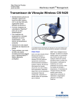
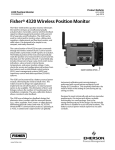
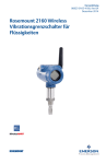
Machinery Health™ Management Product Data Sheet October 2014 CSI 9420 Wireless Vibration Transmitter Accurately monitors vibration and temperature in hard-to-reach locations Provides complete vibration data including overall levels, energy bands, high resolution spectra, and waveforms Enables three ways to collect spectra: time-based, on-alert, and on-demand Includes Emerson’s unique PeakVue™ technology for bearing and gear diagnostics Certified intrinsically safe for use in hazardous areas Delivers data and device alerts securely and reliably via IEC 62591 (WirelessHART®) networks Easily integrates into any host via Modbus or OPC with detailed diagnostics via AMS Suite software Overview The rugged CSI 9420 Wireless Vibration Transmitter is the first device to provide full vibration data over a self-organizing wireless network. It provides rich information about machinery health for both operations and maintenance personnel. Overall vibration, PeakVue, and temperature readings can be easily integrated into any control system or plant historian while diagnostic data can be displayed by AMS Suite: Intelligent Device Manager or any EDDL compliant host. For advanced diagnostics, high resolution data can be delivered to AMS Suite: Machinery Health Manager for trending and analysis. The CSI 9420 delivers complete vibration information, including high resolution spectra and waveform, over a self-organizing wireless network for use by operations and maintenance personnel. Cost-Effective, Reliable Monitoring The CSI 9420 extends vibration monitoring to an entire array of new applications. While appropriate for most vibration monitoring tasks, it is especially well suited for hard-to-reach locations, such as cooling towers, pumping stations, remote equipment, and hazardous areas. In general, the CSI 9420 provides an excellent solution for any application that might otherwise involve extensive engineering, cabling, or installation costs. Advanced electronics deliver a high level of accuracy, while the IEC-approved WirelessHART standard delivers exceptional reliability. Machinery Health™ Management October 2014 Overall Condition in the Control Room Diagnostic Data to the Maintenance Office The CSI 9420 delivers information about the overall health of rotating assets directly to the control room via Modbus or OPC. Overall vibration data is a good indicator of shaft problems such as imbalance, misalignment, or mechanical looseness. In contrast, the PeakVue reading provides a reliable measure of impacting on the machine. As the PeakVue level increases, it provides direct indication of a developing problem, such as improper lubrication, bearing fault, or gear defect. Process induced faults, such as pump cavitation, are detected by an increase in both the overall vibration and PeakVue readings. AMS Machinery Manager automatically communicates detailed diagnostic data to the maintenance office, including overall values, energy bands, high resolution spectra, and waveforms. Once stored in the AMS Machinery Manager database, these measurements deliver the same diagnostic value as comparable readings collected using Emerson’s industry- leading CSI 2140 Machinery Health Analyzer. Asset Dashboard at your Fingertips AMS Device Manager generates an asset dashboard based on the output of the CSI 9420. This intuitive interface displays the health of the sensor, the transmitter, and the production asset being monitored – extending the benefits of PlantWeb® to WirelessHART devices. AMS Machinery Manager provides advanced analytical tools to trend vibration levels, generate alerts, and diagnose developing faults. Information Available When You Need It There are now three ways to collect high-resolution spectra or waveforms: 1) Time-based: Collect readings automatically on a scheduled basis, i.e. once every two weeks. 2) On-alert: Collect readings automatically whenever an alert is registered based on either the overall vibration or the PeakVue impacting. 3) On-demand: Manually initiate a reading at any point when current diagnostic data is required. This allows you to quickly and easily access current health information about your rotating assets without leaving your desk. AMS Device Manager uses EDDL technology to create an asset dashboard with clear indication of device and asset status. AMS Machinery Manager provides advanced analytical tools to trend vibration levels, generate alerts, and diagnose developing faults. Requires AMS Machinery Manager version 5.61 or higher 2 www.assetweb.com Machinery Health™ Management October 2014 Flexible Configuration Options Wireless Architecture Overview The Power to Get Things Done Ultimate Simplicity There are two power options for the CSI 9420. For a truly wireless experience, utilize the SmartPower™ Module. Based on the low power output defined by the WirelessHART standard, the CSI 9420 can achieve an operating life of up to 4 years when using the Power Save option. An operating life of two to three years can be achieved when using the default settings (update rate set to 60 minutes). Built on the IEC 62591 (WirelessHART) industrial standard, Emerson’s wireless network is completely self-organizing. There is no need to configure communication paths because the Smart Wireless Gateway manages this automatically – including adapting to changing environments. Once the network is established, new devices can be added at any time. Conversely, even if a device is de-commissioned, data reporting from other devices continues uninterrupted over other established paths. For faster update rates, the external DC-powered terminal block is recommended. This option provides virtually unlimited operation, even at the minimum update rate of once per minute. Local Indication and Verification The optional LCD display provides a local read-out of sensor values and transmitter diagnostics to streamline commissioning and troubleshooting at the device. Local indication of vibration measurements and diagnostics also provides accurate, real-time verification of operating conditions. The LCD display can be rotated to facilitate easy viewing, regardless of the orientation of the transmitter. Plan and Manage Wireless Networks The AMS Wireless SNAP-ON™ application is a revolutionary tool that enables you to both plan and manage your wireless network. Starting with a scale drawing of the plant, utilize simple click-and-drag functionality to position the gateways and wireless devices. Then the AMS Wireless SNAP-ON application will compare the plan to industry best practices. Recommendations will help you quickly develop a reliable wireless network. Easy Installation The CSI 9420, like all Emerson’s Smart Wireless transmitters, is simple to install. As soon as power is applied to the device, it will automatically establish communication with neighboring wireless devices, establish a path to the Gateway, and begin reporting. Each transmitter also has the ability to function as a repeater, relaying data from other devices to extend the network across virtually any size facility or industrial campus. Network Stability The Smart Wireless Gateway connects the wireless network with the host system and data applications like AMS Suite. The Gateway manages all aspects of the network: executing scheduled readings and accommodating requests for on- demand acquisitions. The Gateway configures the network to minimize power consumption and ensure network stability, while maintaining data reliability well above 99%. After the devices are installed, the AMS Wireless SNAP-ON application will help you manage the network, providing a graphical overview of the communication paths and network health. The AMS Wireless SNAP-ON application graphically displays your wireless network. 3 www.assetweb.com Machinery Health™ Management October 2014 Best-in-Class Security Analyze Data in AMS Machinery Manager Emerson’s multi-layered approach to wireless network security builds on the IEC 62591 standard to ensure that your data stays protected – no matter what. Authentication and verification make certain that only authorized devices can join the network, while 128-bit encryption shields your information. Channel hopping maintains operation, even in challenging environments. Vibration data from the CSI 9420 can be stored and analyzed in AMS Machinery Manager. The Data Import module provides easy data mapping using simple drag-and-drop commands. AMS Machinery Manager combines predictive techniques with comprehensive analysis tools for an accurate assessment of the machinery health in your facility. Emerson’s Complete Smart Wireless Solution Emerson has a complete portfolio of Smart Wireless transmitters for many applications, including temperature, pressure, flow, and level. In addition, the Smart Wireless THUM™ Adapter can enable any HART device to wirelessly transmit measurement and diagnostic information. Emerson wireless devices can be accessed and maintained remotely using the same tools and software as wired devices, leveraging existing practices, training, and maintenance procedures. Detailed Reliability Data Overall vibration indicates when a machine is running rough, while the level of impacting detected by PeakVue signal processing provides the operator with an indication about the presence and severity of a serious defect such as underlubrication, bearing faults, gear defects, and pump cavitation. Furthermore, once a machine has been flagged, detailed data can be analyzed by a vibration specialist to verify the exact nature of the fault. With the advanced diagnostics in the CSI 9420, you have easy access to all of this critical information. High Resolution Waveform The vibration waveform (shown below) is the basis for all other vibration measurements performed by the CSI 9420. Each waveform is a complex data set of thousands of samples, collected over several seconds of machine operation. While the acceleration waveform can be helpful in some applications, the PeakVue waveform is indispensable for diagnosing developing bearing and gear defects. Because of their large size, however, waveforms tend to be collected less frequently. Emerson’s Smart Wireless solution employs several data compression techniques to extract the information while facilitating easier transmission over the network. At the heart of Emerson’s Smart Wireless solution is the selforganizing network, featuring tight security, infinite configurability, and data reliability that rivals wired systems. Seamless Integration to Host Systems Easily configure and broadcast measurements to Emerson’s DeltaV™ and Ovation™ digital automation systems; use Ethernet IP™ to connect to Allen-Bradley® controllers; or apply Modbus or OPC to report data back to most other automation systems and/or data historians. 4 The acceleration waveform contains raw vibration data that allows you to diagnose the health of the asset. www.assetweb.com Machinery Health™ Management October 2014 High Resolution Spectrum Energy Bands The first compression technique is FFT analysis, which transforms the vibration waveform into a frequency spectrum (shown below). This spectrum not only reduces the file size by over 60%, it also presents the frequency information in a more readable format. The smaller data set accelerates responsiveness of the system while reducing power consumption. As a final data compression technique, the CSI 9420 divides the spectrum into three predetermined energy bands (as shown below). It then calculates the vibration energy within each energy band and passes these values to AMS Machinery Manager for trending and alerts. The elevated peaks in this high resolution spectrum provide a clear indication of mechanical looseness on the machine. Band Fault Types Range 1 Rotor Vibration: Imbalance, misalignment (also defects on belt drives) 2–65 Hz 2 Rotor Harmonics: Looseness, electrical faults, blade and vane pass 65–300 Hz 3 High Frequency: Bearing and gear defects, lubrication and cavitation 300–1000 Hz Energy bands with frequency ranges. Optimized for a 4-pole motor running between 1500 and 1800 RPM. Note: bands are fixed. Thumbnail Spectrum The thumbnail spectrum is derived from the same waveform data. It contains the same frequency and amplitude information as the high resolution spectrum, but the data set has been compressed by an additional 98%. Now it is small enough to transfer over the network in less than a second. By dividing the spectrum into energy bands, we can isolate frequencies associated with different categories of faults. The elevated peaks are still clearly visible in the thumbnail spectrum and indicate the presence of mechanical looseness. 5 www.assetweb.com Machinery Health™ Management October 2014 By trending the values in AMS Machinery Manager and comparing them to appropriate alert levels, it is possible to set up a system of intelligent alerts that not only inform you when the machine condition is deteriorating, but also provide information about the underlying cause of the problem. The figure illustrates how vibration data can be used to detect and diagnose a developing fault. Based on the increase in overall vibration (black line), an alert would flag the machine as having a potential fault – but with no indication at all about the nature or severity of the fault. The trend of overall vibration suggests that machine health is deteriorating but without any indication as to the root cause. The trend of the high frequency energy band provides further insight, which can be confirmed by examining the thumbnail spectra. 6 The trend of the three energy bands shows that the readings for rotor vibration (green) and rotor harmonics (blue) are stable, while the readings for high frequency vibration (red) have increased sharply. This would trigger a special alert for the rotating equipment specialist in AMS Machinery Manager. Examination of the thumbnail spectra (shown above the trend) confirms that the fault is high frequency in nature. On-demand acquisition of the PeakVue spectrum and waveform then provides conclusive insight into the specific nature of the fault as well as its severity. Using the advanced diagnostics in the CSI 9420 and AMS Machinery Manager, maintenance personnel can often address and resolve an issue without it ever registering as an alert in the control room. www.assetweb.com Machinery Health™ Management October 2014 Functional Specifications Inputs Accelerometer 1 DC Bias Range: 2 - 3 Vdc DC Input Range: 0 - 5 Vdc AC Input Range: 2.5 Vpeak equivalent to 100 g’s peak (980 m/s2 peak) Accelerometer 2 DC Bias Range: 2 - 3 Vdc DC Input Range: 0 - 5 Vdc AC Input Range: 2.5 Vpeak equivalent to 100 g’s peak (980 m/s2 peak) Temperature DC Input Range: -30° to + 121°C (-22°F to 250°F ) Standard Outputs Machinery Health Values Velocity overall (1 or 2 sensors) PeakVue overall (1 or 2 sensors) Temperature (1 sensor only) Transmitter Health Values Ambient temperature Supply voltage Sensor bias voltage (1 or 2 sensors) Multiple internal alerts indicate the status of device health Advanced Diagnostic Outputs (optional) Energy bands Rotor vibration (2 - 65 Hz) Rotor harmonics (65 - 300 Hz) High Frequency (300 - 1,000 Hz) Thumbnail Spectrum Fmax: 150, 300, 600, or 1,000 Hz High Resolution Vibration Spectrum Fmax: 1,000 Hz Resolution: 400, 800 or 1,600 lines Snapshot or Averaged (4 readings) High Resolution Vibration Waveform All measurements based on high resolution waveform with 4,096 points High Resolution PeakVue Spectrum Bandwidth: 1,000 - 20,000 Hz Fmax: 1,000 Hz Resolution: 1,600 lines Snapshot of impacting on machine High Resolution PeakVue Waveform Sampled at 51,200 Hz; High resolution with 4,096 points Display Units English, metric or SI Local Display The optional five-digit integral LCD display provides readout of HART parameters in engineering units (°F, °C, in/sec, mm/sec, g’s and m/s2). Display updates for each transmission Maximum update rate - once per minute Update Rate Standard: 1 min to 60 min (User selectable) Power Save: up to 24 hours (User selectable) Operating Conditions Relative Humidity 0 - 95% Temperature Storage Temperature: -40°C to 85°C (-40°F to 185°F) Operating Temperature without LCD meter: -40°C to 85°C (-40°F to 185°F) Operating Temperature with LCD display: -20°C to 80°C (-4°F to 176°F) Device software version 6.0 or higher required for 400 line spectrum. 7 www.assetweb.com Machinery Health™ Management October 2014 Physical Specifications Power Options SmartPower™ Module Intrinsically safe Replaceable Lithium-Thionyl Chloride External DC-power Input Voltage: 10 - 28 VDC Provides unlimited operating life — recommended for applications requiring faster update rates Operating Life1 Values apply to Device Software version 5.020 and higher Configuration 1 2 3 Overall Values (min) 30 60 2402 Energy Bands (hr) 8 8 8 Spectrum (hr) 24 24 24 High Resolution Waveform & Spectrum (days) 30 30 30 1 to 2 1.5 to 3 2 to 4 Operating life (years) Materials of Construction Enclosure Housing — Low-copper aluminum (standard) Paint — Polyurethane Cover O-ring — Buna-N Terminal Block and Battery Pack PBT Antenna PBT/PC integrated omni-directional antenna (standard) Optional extended range antenna available in some markets. Mounting Vibration sensor must be mounted directly on asset being monitored Transmitter may be mounted up to 100’ (30.5 m) away from sensor Weight 2 kg (4.6 lbs.) without LCD 2.1 kg (4.7 lbs.) with LCD Enclosure Ratings NEMA 4X / IP66 Performance Specifications ElectroMagnetic Compatibility (EMC) Meets all relevant requirements of EN 61326. Measurement Accuracy RMS Velocity3: +/- 5% from 10 Hz to 800 Hz +/-3 dB from 2 Hz to 1000 Hz PeakVue Impacting +/- 5% from 2000 Hz to 10 kHz +/- 3 dB from 1000 Hz to 20 Khz Temperature: +/- 2°C Measurement Precision Vibration: +/- 0.2 dB Temperature: +/- 2°C Self Calibration The analog-to-digital measurement circuitry automatically self-calibrates for each update by comparing the dynamic measurement to internal reference elements (1) Operating life with a single SmartPower Module is highly dependent on user configuration. Values shown are for operation at an ambient temperature of 21°C (70°F) as part of a well-formed wireless network. Daily measurements are thumbnail spectra. Continuous exposure to extreme temperatures may significantly reduce operating life. Older revisions exhibit a maximum power module life of 2 years at room temperature with a 54 minute burst rate. Actual results depend on the installation process. (2) Burst rates over 60 minutes are configured using the "PowerSave" mode. (3) Measurement accuracy is the absolute accuracy of the measurement relative to a known, calibrated excitation for WirelessHART devices. Values shown represent the expected performance operating under steady-state conditions (20°C with no external interference). 8 www.assetweb.com Machinery Health™ Management October 2014 Vibration Effect No loss in functionality when tested per the requirements of IEC60770-1 with high vibration level (10 Hz to 10 KHz) and up to 50g acceleration RF Output Power (based on maximum device output power of 6.3 mW) Antenna Type Max Gain Max EIRP Standard Long-Range 2.0 dBi 10 mW Extended Range 4.5 dBi 18 mW Sensor and Connections A0394 Sensor Series Nominal Sensitivity 25 mV/g (2.5 mV/m/s2) Frequency Range 96 to 600 Kcpm (1.6 to 10 kHz) Amplitude Range ± 100 g (± 980 m/s2) Broadband Resolution 3 mg rms (0.03 m/s2 rms) Settling Time ≤ 2 sec Temperature Range -40 to +121°C (-40 to +250°F) Weight 23 gm (0.81 oz) Sensor Type Low profile, side exit integral cable Terminal Block Connections Two options for Terminal Block For SmartPower Module Configuration 1: Single Vibration Sensor Connector 1: Red wire Connector 2: White wire Connector 3: Open Connector 4: Black wire Configuration 2: Single Vibration Sensor with Temperature Connector 1: Red wire Connector 2: White wire Connector 3: Green wire Connector 4: Black wire Configuration 3: Two Vibration Sensors Connector 1: Red wires (2 total) Connector 2: White wire (Sensor 1) Connector 3: White wire (Sensor 2) Connector 4: Black wires (2 total) HART Connection Connectors 5 & 6 External Power Connector 7: Negative Connector 8: Positive 9 For External DC Line Power www.assetweb.com Machinery Health™ Management October 2014 Product Certification and Registrations General Certifications Approved Manufacturing Locations Emerson Process Management Knoxville, Tennessee USA Telecommunication Compliance 2.4 GHz WirelessHART FCC ID: LW2RM2510 IC ID: 2731A-RM2510 ATEX Directive (94/9/EC) Emerson Process Management complies with the ATEX Directive. Compliant to Electro Magnetic Compatibility (EMC) (2004/108/EC) All Models conforming to the following standards: EN 61326-1, 61326-2-3: 2006 Country Restriction Bulgaria General authorization required for outdoor use and public service. Italy If used outside of own premises, general authorization is required. Norway May be restricted in the geographical area within a radius of 20 km from the center of Ny-Alesund. Romania Use on a secondary basis. Individual license required. Radio and Telecommunications Terminal Equipment Directive (R&TTE) (1999/5/EC) Emerson Process Management complies with the R&TTE Directive. Canadian Standards Association (CSA) General Safety Standard Certification conforming to the following standards: CSA Std. C22.2 No. 61010-1-4 Safety Requirements for Electrical Equipment for Measurement, Control and Laboratory Use, Part I: General Requirements (Second Edition) ISA S82.02.01 2nd (IEC 61010-1 Mod) Safety Standards for Electrical and Electronic Test, Measuring, Controlling and Related Equipment – General Requirements ANSI/UL Sta. 61010-1 Electrical Equipment for Measurement, Control and Laboratory Use: Part 1 General Requirements (Second Edition) 10 www.assetweb.com Machinery Health™ Management October 2014 Hazardous Location Certification3 (Rev 4 and 5) Factory Mutual (FM) Class I, Division 2, Groups A, B, C, D Intrinsically Safe for Class I, Zone 0, AEx ia IIB; Hazardous (Classified) Locations Temperature Codes T4 (-40°C ≤ Ta ≤ 85°C) (-20°C ≤ Ta ≤ 80°C) with LCD Ambient temperature limits: -40 to 80°C For use with Emerson Battery Pack Model 701PBKKF Only Enclosure Type 4X / IP66 Canadian Standards Association (CSA) CSA for Class I, Division 1, Groups C, D Temp Code T4 (-40°C ≤ Ta ≤ 85°C) (-20°C ≤ Ta ≤ 80°C) with LCD For use with Emerson Battery Pack Model 701PBKKF Only Enclosure Type 4X / IP66 ATEX ATEX Category Marking: II 1 G (-40°C ≤ Ta ≤ 85°C) Ex ia IIB T4 Ga (-20°C ≤ Ta ≤ 80°C) with LCD (-10°C ≤ Ta ≤ 50°C) in case of connection with HART Communicator For use with Emerson Battery Pack Model 701PBKKF Only IECEx IECEx Category Marking: Ex ia IIB T4 Ga (-40°C ≤ Ta ≤ 85°C) (-20°C ≤ Ta ≤ 80°C) with LCD For use with Emerson Battery Pack Model 701PBKKF Only Others Refer to our website for the latest information on country-specific approvals. A non-rated version of the CSI 9420 is also available, which can be operated with either the SmartPower Module or using external line-power (10-28V DC). (3) Every effort is made to reflect current status. Consult factory for most recent information on individual approvals as well as special instructions. CSI 9420 dimensional drawing with long-range and extended range antennas. Dimensions are in mm (inches). 11 www.assetweb.com Machinery Health™ Management October 2014 Are You Wireless? As any plant manager will tell you, you can’t improve something if you can’t measure it. Improved access to information provides the opportunity to reduce operating costs while improving quality, throughput, and availability. Add to that the expanding requirement to certify compliance with new environmental and safety standards. This all points to the need for increased monitoring, yet many managers still believe that the costs outweigh the benefits. With wired systems, that may have been the case; however, wireless networks remove traditional barriers and redefine the cost equation. A wireless network can substantially reduce engineering, material, and implementation costs, and those cost savings are just the beginning. Imagine what you can do with the additional information. Wireless technology can reduce – if not eliminate – the “blind spots” in your plant, while empowering mobile workers by providing needed information. The CSI 9420 provides predictive diagnostics for your essential production assets from virtually any location. The result is increased process uptime, improved consistency, and reduced risk of abnormal situations. As more and more plants are turning to wireless solutions, the question is “Are You Wireless?”. A CSI 9420 is an easy addition to any existing wireless network. ©2014, Emerson Process Management. Emerson Process Management Reliability Solutions 835 Innovation Drive Knoxville, TN 37932 T (865) 675-2400 www.assetweb.com The contents of this publication are presented for informational purposes only, and while every effort has been made to ensure their accuracy, they are not to be construed as warranties or guarantees, express or implied, regarding the products or services described herein or their use or applicability. All sales are governed by our terms and conditions, which are available on request. We reserve the right to modify or improve the designs or specifications of our products at any time without notice. All rights reserved. AMS, PlantWeb, Machinery Health, SNAP-ON, SmartPower, DeltaV, THUM, Ovation, and PeakVue are marks of one of the Emerson Process Management group of companies. The Emerson logo is a trademark and service mark of Emerson Electric Co. All other marks are the property of their respective owners. MHM_PDS_CSI9420WirelessVibTran_1014